Acura RSX Honda Integra. Manual - part 101
−
−
−
−
01
01
S6M6AAJK72100090113FAAT00
−
−
−
−
−
−
DTC P0113:
YES
NO
YES
NO
YES
NO
11-110
PGM-FI System
DTC Troubleshooting (cont’d)
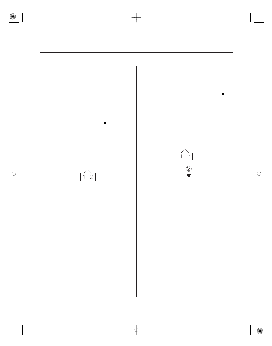
IAT SENSOR 2P CONNECTOR
IAT
(RED/YEL)
SG2
(GRN/YEL)
JUMPER WIRE
IAT SENSOR 2P CONNECTOR
IAT
(RED/YEL)
IAT Sensor Circuit High Voltage
(2002-2004 models)
1. Turn the ignition switch ON (II).
2. Check the IAT with a scan tool or the HDS.
Go to step 3.
Intermittent failure, system is OK at this time.
Check for poor connections or loose terminals at
the IAT sensor and the ECM/PCM.
3. Turn the ignition switch OFF.
4. Disconnect the IAT sensor 2P connector.
5. Connect IAT sensor 2P connector terminals No. 1
and No. 2 with a jumper wire.
6. Turn the ignition switch ON (II).
7. Check the IAT with a scan tool or the HDS.
Go to step 8.
Replace the IAT sensor (see page 11-281).
8. Turn the ignition switch OFF.
9. Remove the jumper wire.
10. Turn the ignition switch ON (II).
11. Measure voltage between IAT sensor 2P connector
terminal No. 2 and body ground.
Go to step 12.
Go to step 15.
12. Turn the ignition switch OFF.
Wire side of female terminals
Wire side of female terminals
Is
4 °F (
20 °C) or less, or 5 V indicated?
Is
4 °F (
20 °C) or less, or 5 V indicated?
Is ther e about 5 V ?
05/06/27 17:33:38 61S6M040_110_0110