Acura RSX Honda Integra. Manual - part 98
01
01
02
S6M6AAJK72100090107FAAT00
−
−
−
−
−
−
−
−
−
−
DTC P0107:
YES
NO
YES
NO
YES
NO
YES
NO
YES
NO
11-98
PGM-FI System
DTC Troubleshooting
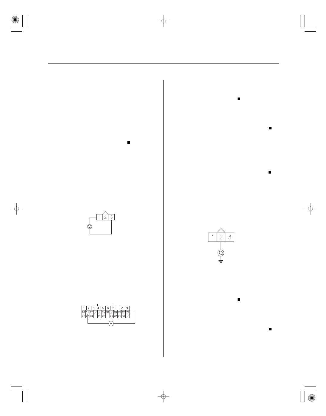
MAP SENSOR 3P CONNECTOR
VCC1
(YEL/RED)
SG1
(GRN/WHT)
ECM/PCM CONNECTOR A (31P)
VCC1
(YEL/RED)
SG1
(GRN/WHT)
MAP SENSOR 3P CONNECTOR
MAP
(GRN/RED)
MAP Sensor Circuit Low Voltage
(2002-2004 models)
1. Turn the ignition switch ON (II).
2. Check the MAP with a scan tool or the HDS.
Intermittent failure, system is OK at this time.
Check for poor connections or loose terminals at
the MAP sensor and the ECM/PCM.
Go to step 3.
3. Turn the ignition switch OFF.
4. Disconnect the MAP sensor 3P connector.
5. Turn the ignition switch ON (II).
6. Measure voltage between MAP sensor 3P
connector terminals No. 1 and No. 3.
Go to step 8.
Go to step 7.
7. Measure voltage between ECM/PCM connector
terminals A11 and A21.
Repair open in the wire between the ECM/
PCM (A21) and the MAP sensor.
Update the ECM/PCM if it does not have the
latest software, or substitute a known-good ECM/
PCM (see page 11-6), then recheck. If the symptom/
indication goes away with a known-good ECM/PCM,
replace the original ECM/PCM (see page 11-284).
8. Check the MAP with a scan tool or the HDS.
Go to step 9.
Replace the MAP sensor (see page 11-412).
9. Turn the ignition switch OFF.
10. Disconnect ECM/PCM connector A (31P).
11. Check for continuity between MAP sensor 3P
connector terminal No. 2 and body ground.
Repair short in the wire between the ECM/
PCM (A19) and the MAP sensor.
Update the ECM/PCM if it does not have the
latest software, or substitute a known-good ECM/
PCM (see page 11-6), then recheck. If the symptom/
indication goes away with a known-good ECM/PCM,
replace the original ECM/PCM (see page 11-284).
Wire side of female terminals
Wire side of female terminals
Wire side of female terminals
Is about 101 kPa ( 30 in.Hg, 7 60 mmHg) or 2.9 V
indicated?
Is ther e about 5 V ?
Is ther e about 5 V ?
Is 2 kPa ( 0.6 in.Hg, 15 mmHg) or less, or 0 V
indicated?
Is ther e continuity?
05/06/27 17:33:36 61S6M040_110_0098