Acura RSX Honda Integra. Manual - part 29


  Index      Acura     Acura RSX Honda Integra - service repair manual 2002-2006 year


Search            


Content   ..  27  28  29  30   ..


Acura RSX Honda Integra. Manual - part 29


14

15

16

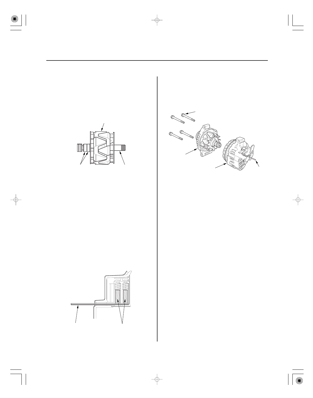
Rotor Slip Ring Test

Alternator Reassembly

4-52

Charging System

Alternator Overhaul (cont’d)

B

A

C

A

B

A

B

C

D

16. Check for continuity between the slip rings (A).

• If there is continuity, go to step 17.
• If there is no continuity, replace the rotor

assembly.

17. Check for continuity between each slip ring (A) and

the rotor (B) and the rotor shaft (C).

• If there is no continuity, replace the rear housing

assembly, go to step 18.

• If there is continuity, replace the rotor assembly.

18. If you removed the pulley, put the rotor in the drive-

end housing, then tighten its locknut to 111 N·m
(11.3 kgf·m, 81.7 lbf·ft).

19. Remove any grease or oil from the slip rings.

20. Push the brushes (A) in, then insert a pin or drill bit

(B) (about 1.8 mm (0.77 in.) diameter) to hold them
there.

21. Heat the rear bearing seat with a 1,000 W hair drier

for about 5 minutes (129

140 °F, 50

60 °C).

22. Put the rear housing assembly (A) and drive-end

housing/rotor assembly (B) together, tighten the
four through bolts (C), and pull out the pin (D).

23. After assembling the alternator, turn the pulley by

hand to make sure the rotor rotates smoothly and
without noise.

24. Install the alternator and drive belt (see page 4-46).

01

S6M6A10A14100012901LAAT00

Exploded View - K20A2, K20Z1 Engines

4-53

WAVE
WASHER

REAR BEARING

BEARING
COVER

ROTOR

BEARING
RETAINER

FRONT BEARING

STATOR THROUGH
BOLT

DRIVE-END
HOUSING

PULLEY

PULLEY
LOCKNUT

TERMINAL
INSULATOR

TERMINAL PLATE

END COVER

REAR HOUSING
ASSEMBLY

INSULATOR
BUSHING

SEAL RING

RECTIFIER
ASSEMBLY

VOLTAGE
REGULATOR

BRUSH
HOLDER

BRUSH HOLDER
INSULATOR

(cont’d)

02

03

04

05

Special Tools Required

Alternator Disassembly

4-54

Charging System

Alternator Overhaul (cont’d)

A

B

A

B

C

D

E

A

B

A

B

C

• Driver 07749-0010000
• Attachment, 42 x 47 mm 07746-0010300

NOTE: Refer to the Exploded View as needed during
this procedure.

1. Test the alternator and regulator before you

remove them (see page 4-39).

2. Remove the alternator (see page 4-46).

3. If the front bearing needs replacing, remove the

pulley locknut with a 10 mm wrench (A) and a
22 mm wrench (B). If necessary, use an impact
wrench.

4. Remove the harness bracket (A), the insulator (B),

the three flange nuts (C) and the screw (D), then
remove the plate terminal (E).

5. Remove the end cover (A) and the dust seal (B).

6. Remove the brush holder (A), the voltage regulator

(B), and the rubber seal (C).

06

07

08

01

4-55

A

B

B

A

B

7. Remove the four screws, then remove the rectifier

(A) and the four insulators (B).

8. Remove the four flange nuts, then remove the rear

housing (A) and the washer (B).

9. If you are not replacing the front bearing and/or

rear bearing, go to step 16. Remove the rotor from
the stator drive end housing.

10. Inspect the rotor shaft for scoring, and inspect the

bearing journal surface in the stator housing for
seizure marks.

• If either the rotor or stator housing is damaged,

replace the alternator.

• If both the rotor and the stator housing are OK,

go to step 11.

11. Remove the rear bearing using a puller as shown.

(cont’d)


Content   ..  27  28  29  30   ..