Acura RL (1996-2004 year). Manual - part 636


  Index      Acura     Acura RL 1996-2004 year - service repair manual


Search            


Content   ..  634  635  636  637   ..


Acura RL (1996-2004 year). Manual - part 636


Flowchart No. 2

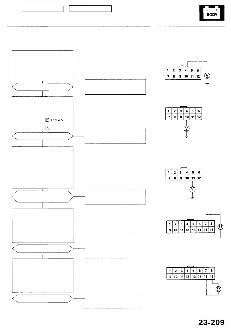
Ignition Key Switch:
Check for voltage between the col-
umn control unit 12P connector A4
terminal and body ground. There
should be 1 V or less with the igni-
tion key inserted and 4 V or more
with the ignition key removed.

Are voltages as specified?

• Open or short in the BLU/WHT

wire

• Faulty ignition key switch

NO

YES

Transmission Range Switch:
Check for voltage between the col-

umn control unit 12P connector

A10 terminal and body ground.
There should be 1 V or less with
the shift lever in or

more with the shift lever in any
other position than

Are voltages as specified?

• Open or short in the BLK/BLU

wire

• Faulty transmission range switch

NO

YES

Vehicle Speed Sensor (VSS):

1. Raise the front of the vehicle,

support it with the safety
stands, put it in neutral, and
slowly rotate one wheel with
other wheel blocked.

2. Check for voltage between the

column control unit 12P con-

nector A11 terminal and body
ground.

• Open or short in the BLU/WHT

wire

• Faulty VSS (see page 

23-86

)

Does voltage pulse from O to
about 5 V or more?

NO

YES

Position Button 1:
Check for continuity between the
column control unit 16P connector
B7 and B16 terminals. There
should be continuity with the posi-

tion button 1 pushed and no conti-

nuity with the position button 1
released.

Is continuity as specified?

• Open or short in the BLU/WHT or

YEL/BLU wires

• Faulty driving position memory

switch

NO

YES

Position Button 2:
Check for continuity between the
column control unit 16P connector
B15 and B16 terminals. There
should be continuity with the posi-
tion button 2 pushed and no conti-
nuity with the position button 2
released.

Is continuity as specified?

NO

• Open or short in the BLU/YEL or

YEL/BLU wires

• Faulty driving position memory

switch

YES

To page 

23-210

NOTE: All connector views are from wire
side of female terminals.

COLUMN CONTROL UNIT
12P CONNECTOR "A"

COLUMN CONTROL UNIT

16P CONNECTOR "B"

(cont'd)

Main Menu

Table of Contents

Driving Position Memory System (DPMS)

Troubleshooting (cont'd)

From page 

23-209

Steering Column Position Sensor:
Check for voltage between the
column control unit 16P connec-
tor B2 and B10 terminals.

NOTE: All column control unit

connectors are must be connected.

Are voltages as specified?

• Open or short in the GRY or BRN

wires

• Faulty steering column position

sensors

NO

YES

NOTE: If necessary, apply power and
ground to the extend-retract motor to
move the steering column to the fully-
extended and fully-retracted positions
(see page 

23-226

).

Steering Column Position Sensor
(Extend-retract):
Check for voltage between the col-

umn control unit 16P connector B9
and B10 terminals. There should
be 2.5 V or more with the steering
column in fully-extended position
and 2.5 V or less with the steering
column in fully-retracted position.
NOTE: All column control unit con-
nectors must be connected.

• Open or short in the PNK or BRN

wires

• Faulty extend-retract position

sensor

NO

Are voltages as specified?

YES

NOTE: If necessary, apply power and
ground to the tilt motor to move the
steering column to the fully-up and fully-
down positions (see page 

23-226

).

Steering Column Position Sensor

(Tilt):
Check for voltage between the col-
umn control unit 16P connector B1
and B10 terminals. There should
be 2.5 V or more with the steering
column in fully-up position and
2.5 V or less with the steering col-
umn in fully-down position.
NOTE: All column control unit con-
nectors must be connected.

Are voltages as specified?

NO

• Open or short in the BLU or BRN

wires

• Faulty tilt position sensor

To page 

23-211

YES

NOTE: All connector views are from wire

side of female terminals.

COLUMN CONTROL UNIT
16P CONNECTOR "B"

Main Menu

Table of Contents

From page 

23-210

CAUTION: Check the sensor carefully
because the motor will run and the
seat will move.

Slide Position Sensor:
Check for voltage between the
seat control unit 12P connector A4
terminal and 16P connector B2
Terminal.

NOTE: Both connectors must be

connected.

NOTE: All connector views are from wire
side of female terminals.

SEAT CONTROL UNIT
12P CONNECTOR "A"

Does voltage pulse between 1 V
or less and 4 V or more with the
slide motor running?

• Open or short in the YEL/GRN or

GRN/BLK wires

• Faulty slide position sensor

NO

YES

Recline Position Sensor:
Check for voltage between the
seat control unit 12P connector A4

terminal and 16P connector B10
terminal.

NOTE: Both connectors must be

connected.

CAUTION: Check the sensor carefully
because the motor will run and the
seat will move.

• Open or short in the WHT/RED or

GRN/BLK wires

• Faulty recline position sensor

NO

Does voltage pulse between 1 V
or less and 4 V or more with the
recline motor running?

Front Up-down Position Sensor:
Check for voltage between the
seat control unit 12P connector A4
terminal and 16P connector B1
terminal.

NOTE: Both connectors must be

connected.

YES

CAUTION: Check the sensor carefully
because the motor will run and the
seat will move.

Does voltage pulse between 1 V or
less and 4 V or more with the front
up-down motor running?

NO

• Open or short in the YEL/BLK or

GRN/BLK wires

• Faulty front up-down position

sensor

YES

CAUTION: Check the sensor carefully
because the motor will run and the
seat will move.

Rear Up-down Position Sensor:
Check for voltage between the
seat control unit 12P connector A4
terminal and 16P connector B9
terminal.

NOTE: Both connectors must be

connected.

• Open or short in the WHT or

GRN/BLK wires

• Faulty rear up-down position

sensor

NO

Does voltage pulse between 1 V
or less and 4 V or more with the
rear up-down motor running?

YES

To page 

23-212

(cont'd)

SEAT CONTROL UNIT

16P CONNECTOR "B"

Main Menu

Table of Contents

Driving Position Memory System (DPMS)

Troubleshooting (cont'd)

From page 

23-211

Power Mirror Position Sensor
(Common):

1. Connect the all mirror control

unit connectors.

2. Turn the ignition switch ON (II).
3. Check for voltage between the

mirror control unit 16P connec-

tor B8 and B16 terminals.

Is there 5 V?

NO

• Open or short in the RED/BLK or

BRN/WHT wire

• Faulty power mirror position

sensor

YES

Right Power Mirror Position Sen-
sor (Horizontal):
Check for voltage between the
mirror control unit 16P connector

B7 and B8 terminals. As the mir-
ror tilts from side to side, voltage
changes from about 1 V to 3 V.

• Open or short in the RED/BLK or

GRN wire

• Faulty right power mirror posi-

tion sensor

Are voltages as specified?

NO

YES

Right Power Mirror Position Sen-
sor (Vertical):
Check for voltage between the mir-
ror control unit 16P connector B8
and B15 terminals. As the mirror
swings from up to down, voltage
changes from about 3 V to 1 V.

Are voltages as specified?

• Open or short in the RED/BLK or

GRY wire

- Faulty left power mirror posi-

tion sensor

NO

YES

Left Power Mirror Position Sen-
sor (Horizontal):
Check for voltage between the
mirror control unit 16P connector
B6 and B8 terminals. As the mir-
ror tilts from up to down, voltage
changes from about 1 V to 3 V.

Are voltages as specified?

NO

• Open or short in the RED/BLK or

GRN/WHT wire

• Faulty left power mirror posi-

tion sensor

YES

To page 

23-213

NOTE: All connector views are from wire
side of female terminals.

MIRROR CONTROL UNIT
16P CONNECTOR "B"

Main Menu

Table of Contents


Content   ..  634  635  636  637   ..