Acura RL (1996-2004 year). Manual - part 583


  Index      Acura     Acura RL 1996-2004 year - service repair manual


Search            


Content   ..  581  582  583  584   ..


Acura RL (1996-2004 year). Manual - part 583


Door and Side Moldings

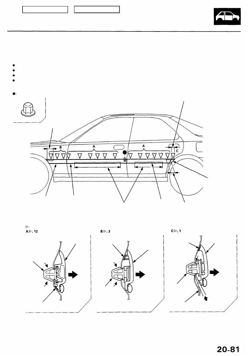
Removal — '96 - 98 Models

CAUTION: When prying with a flat- tip screwdriver, wrap it with protective tape to prevent damage.

NOTE:

To remove the front side molding, remove the inner fender (see page 

20-85

).

To remove the door molding, remove the door panel (see pages 

20-4

, 

20-11

) and plastic cover (see pages 

20-2

, 

20-9

).

To remove the rear side molding, insert a flat-tip screwdriver between the body and molding, then detach the clip.
Take care not to bend the door moldings.

Plastic nut location, 1

Adhesive area.

FRONT SIDE FRONT DOOR
MOLDING MOLDING

REAR SIDE
MOLDING

Adhesive areas.

REAR DOOR

MOLDING Adhesive area.

CLIP

CLIP

ADHESIVE
TAPE

CLIP

PROTECTIVE
TAPE

Adhesive area.

Clip locations

DOOR
MOLDING

ADHESIVE
TAPE

ADHESIVE
TAPE

REAR
SIDE
MOLDING

FRONT
SIDE
MOLDING

Main Menu

Table of Contents

Door and Side Moldings

Removal — '99 - 01 Models

CAUTION: When prying with a flat-tip screwdriver, wrap it with protective tape to prevent damage.

NOTE:

To remove the front side molding, remove the inner fender (see page 

20-85

).

To remove the door molding, remove the door panel (see pages

 20-4

, 

20-11

) and plastic cover (see pages 

20-2

, 

20-9

).

To remove the rear side molding, insert a flat-tip screwdriver between the body and molding, then detach the clip.
Take care not to bend the door moldings.

Plastic nut location,1

FRONT DOOR MOLDING

Adhesive area.

FRONT SIDE
MOLDING

REAR SIDE
MOLDING

REAR DOOR
MOLDING

Adhesive areas. Adhesive area.

CLIP

CLIP

ADHESIVE
TAPE

FRONT
SIDE

MOLDING

ADHESIVE
TAPE

REAR
SIDE

MOLDING

ADHESIVE
TAPE

DOOR
MOLDING

ADHESIVE
TAPE

ADHESIVE
TAPE

Clip locations

ADHESIVE
TAPE

CLIP

Main Menu

Table of Contents

If the old molding is to be reinstalled:

The following materials and tools are required to repair
the molding.

NOTE: Follow the manufacturer's instructions.

Materials: (Reference)

Stripe remover
3M 08907
Stripe adhesive remover
3M 08908
Adhesive tape
3M Super Automotive Attachment Tape

Tools:

Protective tape
Knife or cutter
Sponge or shop towel
Infrared dryer

Film
Putty knife

Alcohol

CAUTION: Put on gloves to protect your hands.

1. If necessary, replace any damaged clips on the mold-

ing.

2. Apply the stripe remover evenly to the bonding sur-

face of the body and molding.

3. Cover the bonding surface of the body and molding

with a film, then heat to 104 - 122°F (40 - 50°C) for 5
- 10 minutes with an infrared dryer.

NOTE: Use care when heating to prevent deforma-

tion of the body and molding.

4. Scrape the adhesive tape with a putty knife.

5. For removal of adhesive tape residue, follow-up with

stripe adhesive remover, then scrape the adhesive
tape with a putty knife.

6. Remove the protective tape, then clean the bonding

surface with a sponge dampened in alcohol.

NOTE: Make sure the bonding surface is kept free of

water, oil, and grease.

7. Glue the new adhesive tape to the moldings as

shown.

: Adhesive tape locations

Width: 5 mm (0.2 in.)
Thickness: 1.2 mm (0.05 in.)

Forward

FRONT SIDE
MOLDING

FRONT DOOR
MOLDING

820 mm (32.3 in.)

REAR SIDE
MOLDING

REAR DOOR
MOLDING

ADHESIVE TAPE
Width: 5 mm (0.2 in.)
Thickness: 0.8 mm (0.03 in.)

8. Heat the bonding surface of the door and molding

with an infrared dryer.

Door: 104- 140°F (40-60°C)
Molding: 68 - 86°F (20 - 30°C)

NOTE: Use care when heating to prevent deforma-

tion of the molding.

9. Align the molding with the clip locations and set the

molding. Lightly push on the molding until its edge
is fully seated on the adhesive tape.

NOTE: Do not spray water on the molding within

the first 24 hours after installation.

10. Reassemble all removed parts.

560 mm (22 in.)

65 mm
2.6 in.)

20 mm
(0.79 in.)

65 mm

(2.6 in.)

Main Menu

Table of Contents

Side Sill Panel

Removal

NOTE: Take care not to scratch the body.

: Clip locations

: Screw locations, 4

NOTE: Loosen the screw, SIDE CLIP

then remove the lower clip Remove the side clips from the body

using a clip remover. by turning them 45°

INNER
FENDER

SIDE CLIP

LOWER
CLIP

SIDE SILL
PANEL

SIDE
CLIPS

 Forward

NOTE: When removing the side
sill panel, the side clips will
stay in the body.

SIDE SILL PANEL

Remove the lower clips,

then remove the side sill panel

by sliding it forward.

To install the side sill panel, remove the side clips from the body, install them on the side sill panel, then install the side

sill panel on the body.

NOTE:

Take care not to twist the side sill panel.

If necessary, replace any damaged side and lower clips.

Main Menu

Table of Contents


Content   ..  581  582  583  584   ..