Acura RL (1996-2004 year). Manual - part 551
DTC 61, 62: +B-FSR Voltage
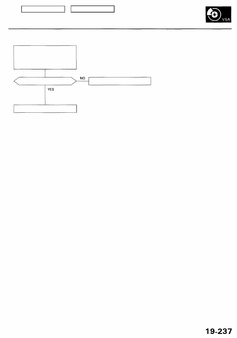
Problem verification:
1. Clear the DTC.
2. Test drive the vehicle at 6 mph
(10 km/h) or more.
3. Verify the DTC.
Is DTC 61 or 62 indicated?
The system is OK at this time.
Check the charging system.
Main Menu
Table of Contents