Acura RL (1996-2004 year). Manual - part 548
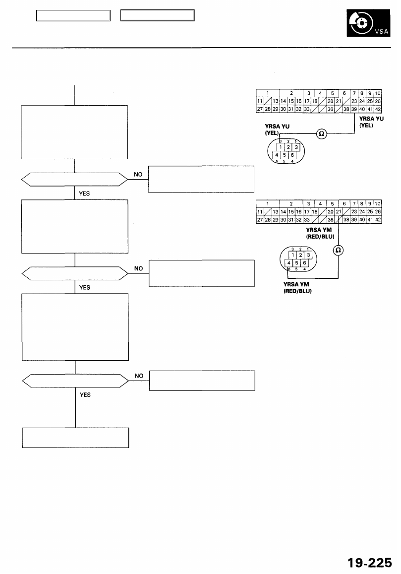
VSA CONTROL UNIT 42P CONNECTOR
Check for an open in the YRSA
YU circuit:
Check for continuity between the
VSA control unit 42P connector
terminal No. 39 and the yaw rate/
lateral acceleration sensor 6P
connector terminal No. 1.
YAW RATE/LATERAL
ACCELERATION SENSOR
6P CONNECTOR
Is there continuity?
Repair open in the wire between
the yaw rate/lateral acceleration
sensor and the VSA control unit.
Wire side of
female terminals
Check for an open in the YRSA
YM circuit:
Check for continuity between the
VSA control unit 42P connector
terminal No. 21 and the yaw rate/
lateral acceleration sensor 6P
connector terminal No. 4.
Is there continuity?
Repair open in the wire between
the yaw rate/lateral acceleration
sensor and the VSA control unit.
Check the yaw rate sensor:
1. Substitute a known-good yaw
rate/lateral acceleration sensor.
2. Connect all of disconnected
connector.
3. Clear the DTC.
4. Test drive the vehicle around a
number of corners.
5. Verify the DTC.
Is DTC 25 indicated?
Replace the yaw rate/lateral
acceleration sensor.
Replace the VSA modulator-
control unit.
Wire side of
female terminals
Main Menu
Table of Contents