Acura RL (1996-2004 year). Manual - part 547
DTC 11, 13, 15, 17: Wheel Sensor (Open/Short to Body Ground/Short to Power)
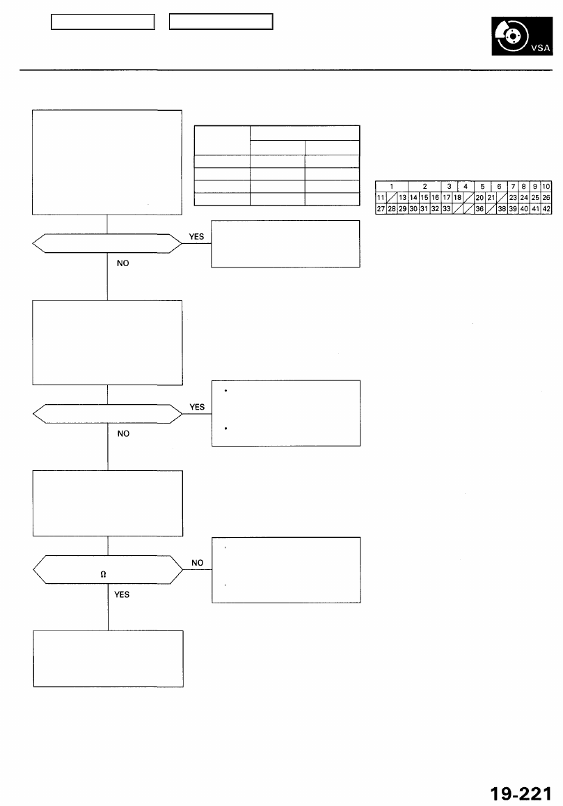
Check for a short to power in the
wheel sensor circuit:
1. Disconnect the VSA control
unit 42P connector.
2. Start the engine.
3. Measure the voltage between
the VSA control unit 42P con-
nector appropriate wheel sen-
sor (+) circuit terminal and
body ground (see table).
DTC
11 (Right-front)
13 (Left-front)
15 (Right-rear)
17 (Left-rear)
Appropriate Terminal
(+) Side
No. 16:FRS(+)
No. 28:FLS(+)
No. 31: RRS (+)
No.14: RLS(+)
(-) Side
No. 15: FRS(-)
No. 13:FLS (-)
No. 30: RRS (-)
No. 29: RLS (-)
VSA CONTROL UNIT 42P CONNECTOR
Is there battery voltage?
Repair short to power in the {+)
or (-) circuit wire between the
VSA control unit and appropriate
wheel sensor.
Wire side of female terminals
Check for a short to body ground
in the wheel sensor circuit:
1. Turn the ignition switch OFF.
2. Check for continuity between
the VSA control unit 42P con-
nector appropriate wheel sen-
sor (+) circuit terminal and
body ground (see table).
Is there continuity?
Repair short to body ground in
the (+) or (-) circuit wire between
the VSA control unit and the
appropriate wheel sensor.
Replace the appropriate wheel
sensor.
Check for an open in the wheel
sensor circuit:
Measure the resistance between
the VSA control unit 42P connector
appropriate wheel sensor (+) and
(-) circuit terminals (see table).
Is the resistance between
450 - 2,000 at 68°F?
• Repair open in the (+) or (-) cir-
cuit wire between the VSA con-
trol unit and the appropriate
wheel sensor.
• Replace the appropriate wheel
sensor.
Check for loose terminals in the
VSA control unit 42P connector.
If necessary, substitute a known-
good VSA modulator-control
unit, and recheck.
Main Menu
Table of Contents