Acura RL (1996-2004 year). Manual - part 513


  Index      Acura     Acura RL 1996-2004 year - service repair manual


Search            


Content   ..  511  512  513  514   ..


Acura RL (1996-2004 year). Manual - part 513


Troubleshooting

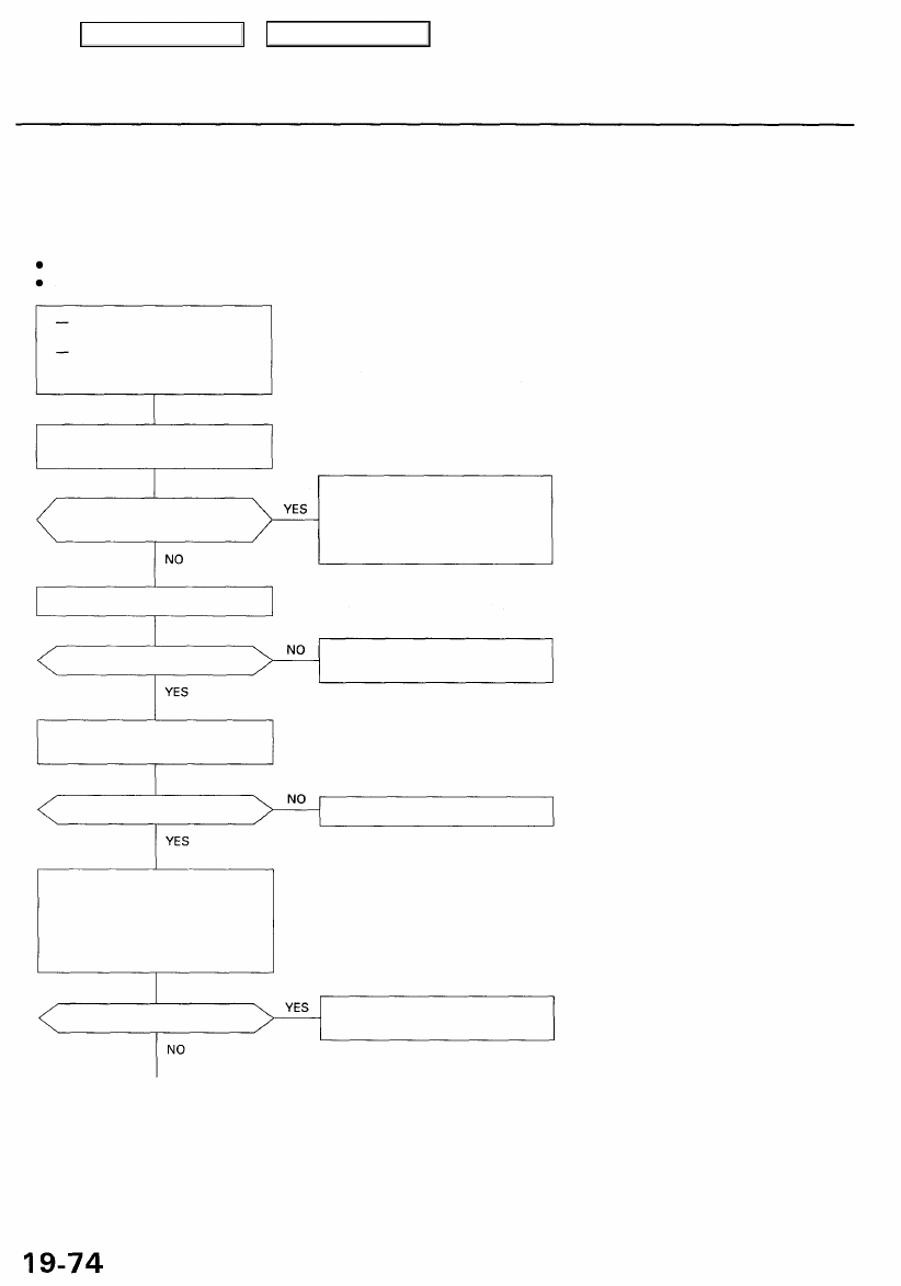
DTC 6-4: Rear Fail-safe Relay

The ABS control unit monitors the voltage from the battery for the six solenoids during the initial diagnosis when the fail-

safe relays are OFF. The ABS control unit keeps the ABS indicator light on if it detects the battery voltage at the two rear

solenoid circuits.

Possible causes:

Rear fail-safe relay stuck ON

Short to power in the solenoid drive circuits between the rear fail-safe relay and ABS control unit

Does the ABS indicator light go
off?

The ABS is OK at this time. Check
for damaged wire harness bet-
ween the ABS control unit, sole-

noid and rear fail-safe relay
(intermittent short to power).

Is code 6-4 indicated?

Perform the appropriate trouble-
shooting for the code.

Check the rear fail-safe relay (see

section 23

).

Is the relay OK?

Replace the rear fail-safe relay.

Check the modulator wire har-

ness:
1. Disconnect the modulator unit

14P connector.

2. Visually check the modulator

wire harness.

Is there a short to power?

Replace the modulator wire har-
ness (or repair short).

(To page 

19-75

)

Confirm the DTC that appears first.

Problem verification:
Start the engine.

With engine running, ABS indi-
cator light is ON.
With the SCS service connec-
tor connected (see page

19-40

), DTC 6-4 is indicated.

Main Menu

Table of Contents

(From page 

19-74

)

REAR FAIL-SAFE RELAY CONNECTOR

Check for a short to power in the
SOLENOID circuit:

1. Start the engine.

2. Measure the voltage between

the rear fail-safe relay connec-
tor terminal No. 1 and body
ground.

NOTE: The fail-safe relays are OFF when the

ABS indicator light is kept on.

SOLENOID
(BLU/BLK)

Is there battery voltage?

Repair short to power in the wire
between the rear fail-safe relay
and modulator unit.

Terminal side of female terminals

Check for a short to power in the
R-IN circuit:

1. Turn the ignition switch OFF.

2. Disconnect the ABS control unit

26P connector.

3. Start the engine.
4. Measure the voltage between

terminal No. 3 and body ground.

NOTE: Check with the modulator unit UP

connector disconnected.

Is there battery voltage?

Repair short to power in the wire
between the ABS control unit
and modulator unit.

Wire side of female terminals

Check for a short to power in the
R-OUT circuit:

Measure the voltage between the

ABS control unit 26P connector
terminal No. 16 and body ground.

Is there battery voltage?

Repair short to power in the wire
between the ABS control unit
and modulator unit.

Check for loose ABS control unit
connectors. If necessary, substi-
tute a known-good ABS control
unit and recheck.

ABS CONTROL UNIT 26P CONNECTOR

Main Menu

Table of Contents

Troubleshooting

DTC 7-1: Right-front Solenoid

During the initial diagnosis, after the fail-safe relays are turned on, and during the regular diagnosis, the ABS control unit
monitors the voltage from the battery for the six solenoids (when the ABS is not functioning). If the detection circuit for

the right-front solenoid detects 0 V, the ABS control unit keeps the ABS indicator light on after the engine is started. It
turns the ABS indicator light on again if it detects 0 V after the light goes off.

Possible causes:

Open circuit in the right-front solenoid drive circuits between the front fail-safe relay and ABS control unit
Short circuit to body ground in the right-front solenoid drive circuits between the solenoids and ABS control unit
Faulty right-front solenoid drive transistor (ON) in the ABS control unit

The ABS control unit momentarily outputs the ON signal to each solenoid (too momentary to turn the solenoid on) during
the initial diagnosis, and each time the vehicle is driven, to check the voltage from the battery with the detection circuit. If
the detection circuit for the right-front solenoids detects battery voltage at this time, the ABS control unit keeps the ABS

indicator light on. It turns the ABS indicator light on again if it detects battery voltage when the vehicle is driven.
Possible causes:

Short circuit to power in the right-front solenoid drive circuits between the solenoids and ABS control unit
Faulty right-front solenoid drive transistor (OFF) in the ABS control unit
Short circuit to power in the right-front solenoid drive circuits in the modulator wire harness or solenoids
Short circuit to the right-front solenoid outlet circuit in the inlet circuit between the solenoid and ABS control unit

Does the ABS indicator light go
off?

The system is OK at this time.
Check the wire harness and con-
nectors between the ABS control

unit, fail-safe relay and modulator
unit (intermittent open or short
circuit).

Is code 7-1 indicated?

Perform the appropriate trouble-
shooting for the code.

(To page 

19-77

)

Confirm the DTC that appears first.

Problem verification:
Start the engine.

With engine running, ABS indi-
cator light is ON.
With the SCS service connec-
tor connected (see page

19-40

), DTC 7-1 is indicated.

Main Menu

Table of Contents

(From page 

19-76

)

Check for an open in the SOLE-
NOID circuit:

1. Remove the front fail-safe

relay.

2. Connect the front fail-safe relay

connector terminals No. 1 and

No. 2 using a jumper wire.

3. Disconnect the modulator unit

14P connector.

4. Measure the voltage between

body ground and terminals
No. 5 and No. 8 individually.

Is there battery voltage?

is the resistance as specified?
Inlet: 2.5-2.9 or 6.5-7.5
Outlet: 2.5- 2.9 or 3.3-3.9

Check for a short to body ground
in the solenoid:
Check for continuity between

body ground and the modulator
unit 14P connector terminals
No. 1 and No. 12 individually.

Is there continuity?

(To page 

19-78

)

Repair open in the wire(s)
between the front fail-safe relay
and modulator unit.

NOTE:

Inlet Solenoid

Outlet Solenoid

STANDARD RESISTANCE

A TYPE

2.5-2.9

2.5-2.9

B TYPE

6.5-7.5

3.3 - 3.9

Terminal side of male terminals

Visually inspect the modulator
wire harness. If the harness is
OK, replace the modulator unit.

(Open or short in the right-front
inlet or outlet solenoid)

Wire side of female terminals

Visually inspect the modulator
wire harness. K the harness is OK,
replace the modulator unit. (Short
to body ground in the right-front

inlet or outlet solenoid)

FRONT FAIL-SAFE RELAY CONNECTOR

JUMPER WIRE

Terminal side of female terminals

MODULATOR UNIT 14P CONNECTOR

MODULATOR UNIT 14P CONNECTOR

Main Menu

Table of Contents


Content   ..  511  512  513  514   ..