Acura RL (1996-2004 year). Manual - part 384


  Index      Acura     Acura RL 1996-2004 year - service repair manual


Search            


Content   ..  382  383  384  385   ..


Acura RL (1996-2004 year). Manual - part 384


(From page 

11-104

)

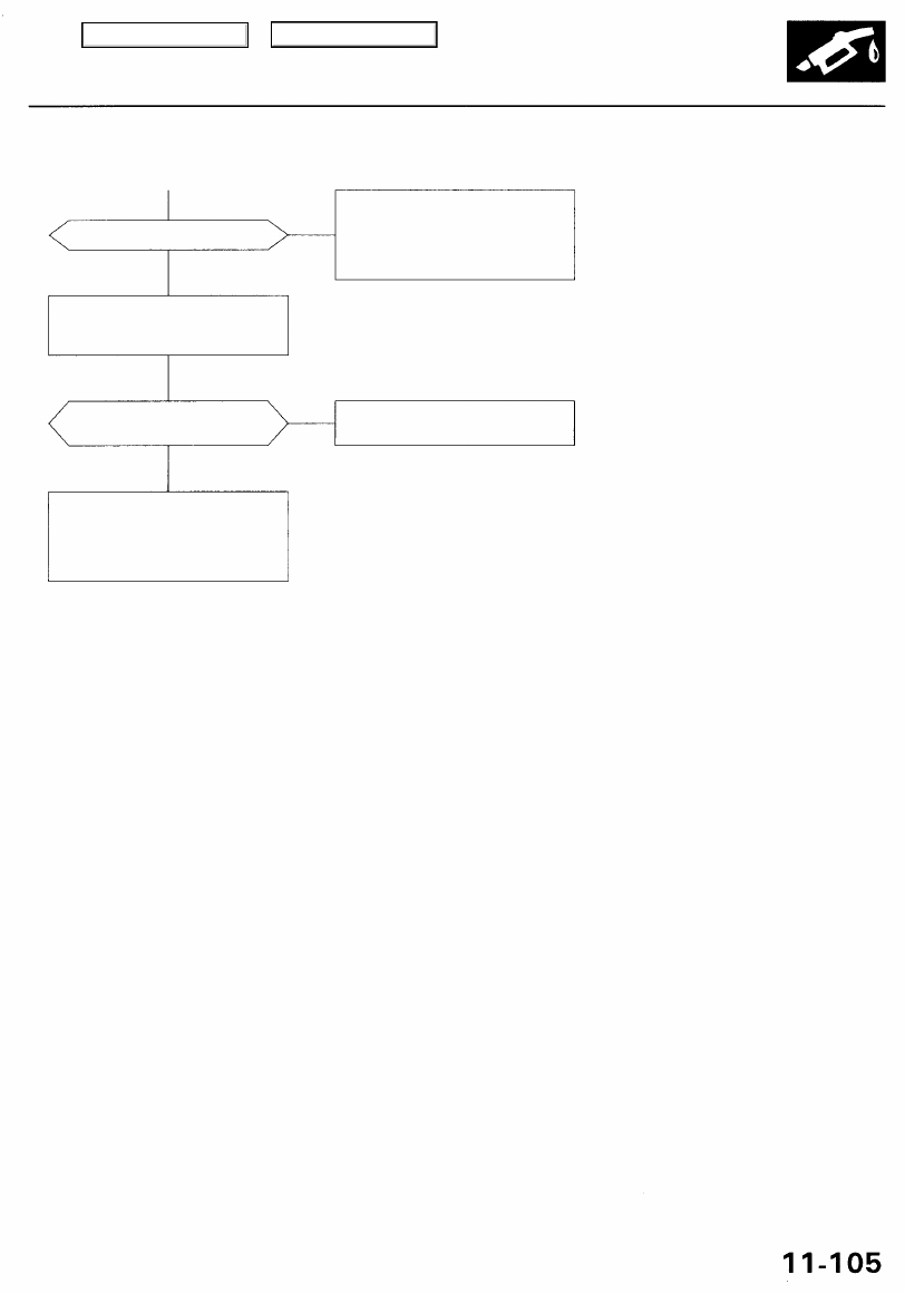
Is there battery voltage?

YES

Repair open in the wire between
No. 20 ECU (PCM) (20 A) fuse in

the under-dash fuse/relay box

and spark plug voltage detection
module.

Substitute a known-good spark
plug voltage detection module
and recheck.

Is DTC P1318 and/or P1319
indicated?

Replace the original spark plug

voltage detection module.

YES

Substitute a known-good PCM
and recheck (see page 

11-42 

for

immobilizer information). If symp-

tom/indication goes away, replace
the original PCM.

NO

NO

Main Menu

Table of Contents

PGM-FI System

Crankshaft Position/Cylinder Position (CKP/CYP) Sensor

The scan tool indicates Diagnostic Trouble Code (DTC) P0335: A malfunction in the circuit of the Crankshaft

Position (CKP) sensor 1.

The scan tool indicates Diagnostic Trouble Code (DTC) P0336: An intermittent interruption problem of the
Crankshaft Position (CKP) sensor 1.

The scan tool indicates Diagnostic Trouble Code (DTC) P1337: A malfunction in the circuit of the Crankshaft
Position (CKP) sensor 2.

The scan tool indicates Diagnostic Trouble Code (DTC) P1336: An intermittent interruption problem of the
Crankshaft Position (CKP) sensor 2.

The scan tool indicates Diagnostic Trouble Code (DTC) P1381: An intermittent interruption problem of the

Cylinder Position (CYP) sensor 1.

The scan tool indicates Diagnostic Trouble Code (DTC) P1382: A malfunction in the circuit of the Cylinder Positior

(CYP) sensor 1.
The scan tool indicates Diagnostic Trouble Code (DTC) P1386: An intermittent interruption problem of the
Cylinder Position (CYP) sensor 2.

The scan tool indicates Diagnostic Trouble Code (DTC) P1387: A malfunction in the circuit of the Cylinder Position

(CYP) sensor 2.

Problem verification:

1. Do the PCM Reset Procedure.

2. Start the engine.

Is DTC P0335, P0336, P1337, P1336,
P1381, P1382, P1386 and/or P1387
indicated?

Check for an open in the CKP/CYP
sensor:

1. Turn the ignition switch OFF.

2. Disconnect the CKP/CYP 8P

connector.

3. Measure resistance between

the terminals of the indicated
sensor (see table).

Is there 650 - 850

YES

Check for a short in the CKP/CYP
sensor:
Check for continuity to body
ground on both terminals of the

indicated sensor.

CYP PICK-UP
COIL 2

CYP PICK-UP
COIL 1

Intermittent failure, system is OK
at this time. Check for poor con-
nections or loose wires at C251,
C255 (located at left shock tower),
C130 (CKP/CYP) sensor and PCM.

Replace the CKP/CYP sensor (see

section 6

).

CKP/CYP SENSOR 8P CONNECTOR

Terminal side of male terminals

(To page 

11-107

)

NO

YES

NO

CKP PICK-UP
COIL 1

CKP PICK-UP
COIL 2

The CKP Sensor determines timing for injection and ignition of each cylinder and also detects engine speed.
The CYP Sensor detects the position of No. 1 cylinder for sequential injection to each cylinder. The CKP/CYP Sensor is

installed behind the front camshaft pulley.

— The MIL has been reported on.
— DTC P0335, P0336, P1337

P1336, P1381, P1382, P1386
and/or P1387 are stored.

Main Menu

Table of Contents

(From page 

11-106

)

Is there continuity?

Replace the CKP/CYP sensor (see

section 6

).

NO

Check for an open in the wires

(CKP/CYP lines):

1. Reconnect the CKP/CYP 8P

sensor connector.

2. Disconnect the PCM connec-

tor B (16P) and D (22P).

3. Measure resistance between

the terminals of the indicated

sensor on the PCM connector
(see table).

PCM CONNECTORS

Wire side of female terminals

Is there 650 - 850

YES

Check for a short in the wires
(CKP/CYP lines):
Check for continuity between PCM
connector terminals B5, B6, B7, B8
and body ground.

Is there continuity?

NO

Repair short to body ground in

the indicated sensor wires (see
table).

Substitute a known-good PCM
and recheck (see page 

11-41 

for

immobilizer information). If symp-

tom/indication goes away, replace
the original PCM.

YES

NO

YES

Main Menu

Table of Contents

PGM-FI System

Barometric Pressure (Baro) Sensor

The scan tool indicates Diagnostic Trouble Code (DTC) P1106: A range/performance problem in the Barometric

Pressure (BARO) Sensor circuit.

Is DTC P1106 indicated?

Intermittent failure, system is OK
at this time.

YES

Substitute a known-good PCM
and recheck (see page 

11-42 

for

immobilizer information). If symp-
tom/indication goes away, replace
the original PCM.

NO

Problem verification:

1. Do the PCM reset procedure.

2. Connect the SCS service con-

nector.

3. Start the engine. Hold the

engine at 3,000 rpm with no
load (in Park or neutral) until
the radiator fan comes on,
then let it idle.

4. Test-drive with the transmis-

sion in position.

5. Accelerate for five seconds

using wide open throttle.

— The MIL has been reported on.
— DTC P1106 is stored.

Main Menu

Table of Contents


Content   ..  382  383  384  385   ..