Acura RL (1996-2004 year). Manual - part 380


  Index      Acura     Acura RL 1996-2004 year - service repair manual


Search            


Content   ..  378  379  380  381   ..


Acura RL (1996-2004 year). Manual - part 380


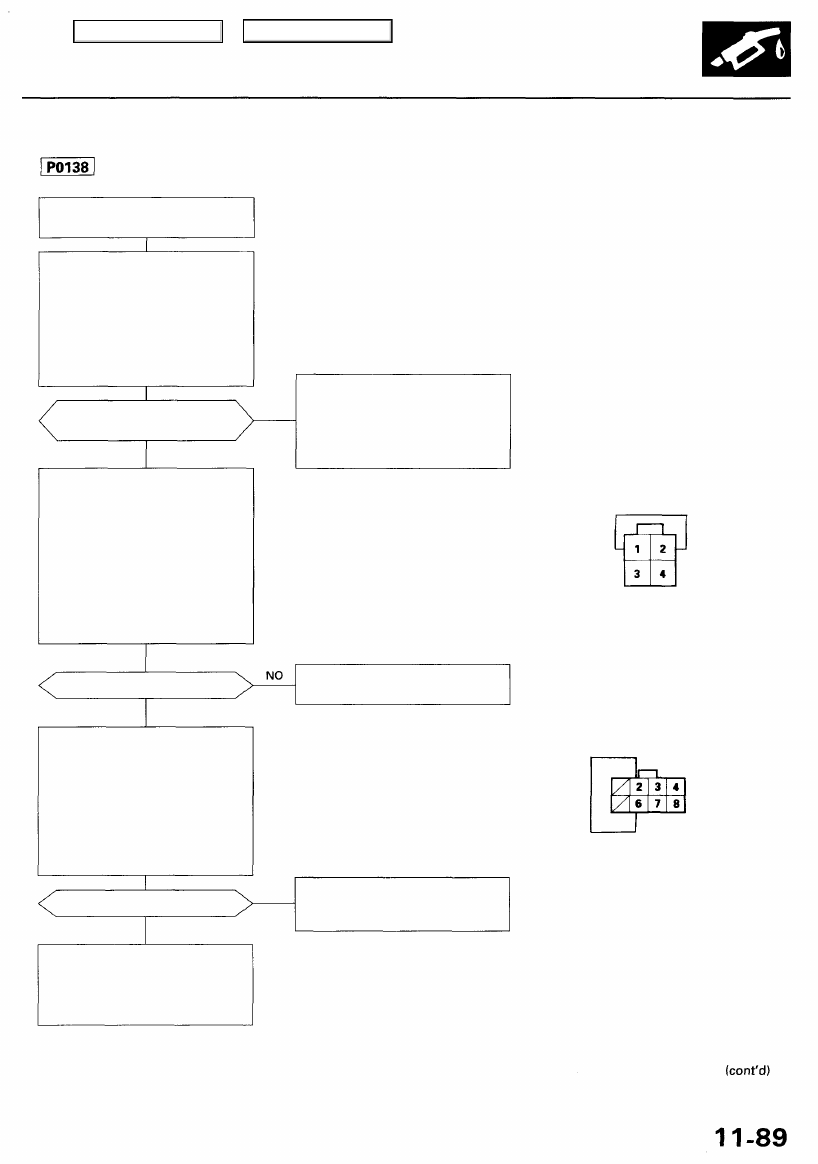
The scan tool indicates Diagnostic Trouble Code (DTC) P0138: A high voltage problem in the Secondary Heated

Oxygen Sensor (HO2S) (Sensor 2) circuit.

— The MIL has been reported on.
— DTC P0138 is stored.

Problem verification:

1. Do the PCM Reset Procedure.

2. Start the engine. Hold the

engine at 3,000 rpm with no
load (in Park or neutral) until
the radiator fan comes on.

3. Check the secondary HO2S

(Sensor 2) output at 3,000 rpm
voltage with the scan tool.

Does the voltage stay at 0.6 V
or more?

YES

Check for an open in the HO2S:

1. Turn the ignition switch OFF.

2. Disconnect the secondary

HO2S (Sensor 2) connector.

3. Install a jumper wire between

the secondary HO2S (Sensor 2)

connector (harness side) No. 1
terminal and No. 2 terminal.

4. Turn the ignition switch ON (II).
5. Check the secondary HO2S

(Sensor 2) output voltage with

the scan tool.

Is there 0.6 V or more?

YES

Check for an open in the wire
(SO2S line):

1. Turn the ignition switch OFF.

2. Install a jumper wire between

the PCM connector terminals

F2 and F6.

3. Turn the ignition switch ON (II).
4. Check the secondary HO2S

(Sensor 2) output voltage with

the scan tool.

Is there 0.6 V or more?

YES

Substitute a known-good PCM
and recheck (see page 

11-42 

for

immobilizer information). If symp-

tom/indication goes away, replace
the original PCM.

NO

Intermittent failure, system is OK
at this time. Check for poor con-
nections or loose wires at C444
(located behind right kick panel),
C610 (secondary HO2S (Sensor

2)) and PCM.

SECONDARY HO2S (Sensor 2) CONNECTOR (C610)

SHO2S
(WHT/
RED)

SO2S GND
(GRN/WHT)

Wire side of female terminals

Replace the secondary HO2S (Sen-
sor 2).

JUMPER
WIRE

SO2S GND
(GRN/WHT)

Repair open in the wire between
PCM (F2) or (F6) and secondary
HO2S (Sensor 2).

Wire side of female terminals

NO

PCM CONNECTOR F (8P)

SO2S
(WHT/RED)

JUMPER WIRE

Main Menu

Table of Contents

PGM-FI System

Secondary Heated Oxygen Sensor (HO2S) (Sensor 2) (cont'd)

Does the voltage stay within
0.3 - 0.6 V for 2 minutes?

NO

Intermittent failure, system is OK
at this time. Check for poor con-
nections or loose wires at C444
(located behind right kick panel),
C610 (secondary HO2S (Sensor

2)) and PCM.

The scan tool indicates Diagnostic Trouble Code (DTC) P0139: A slow response problem in the Secondary

Heated Oxygen Sensor (Secondary HO2S) (Sensor 2) circuit.

— The MIL has been reported on.
— DTC P0139 is stored.

Problem verification:

1. Do the PCM Reset Procedure.

2. Start the engine. Hold the

engine at 3,000 rpm with no
load (in Park or neutral) until

the radiator fan comes on.

3. Check the secondary HO2S

(Sensor 2) or output at 3,000
rpm with the scan tool.

Replace the secondary HO2S (Sen-
sor 2).

YES

Main Menu

Table of Contents

Heated Oxygen Sensor (HO2S) Heater

The scan tool indicates Diagnostic Trouble Code (DTC) P0135: A problem in the Right Primary Heated Oxygen

Sensor (Right Primary HO2S) (Bank 1, Sensor 1) Heater circuit.

The scan tool indicates Diagnostic Trouble Code (DTC) P0141: A problem in the Secondary Heated Oxygen

Sensor (Secondary HO2S) (Sensor 2) Heater circuit.

The scan tool indicates Diagnostic Trouble Code (DTC) P0155: A problem in the Left Primary Heated Oxygen

Sensor (Left Primary HO2S) (Bank 2, Sensor 1) Heater circuit.

— The MIL has been reported on.
— DTC P0135, P0141 and/or

P0155 are stored.

Problem verification:

1. Do the PCM Reset Procedure.

2. Start the engine.

Is DTC P0135, P0141 or P0155
indicated?

YES

Check for an open or short in the

HO2S:
1. Turn the ignition switch OFF.
2. Disconnect the right primary

HO2S (Bank 1, Sensor 1), sec-
ondary HO2S (Sensor 2)*

1

 or

left primary HO2S (Bank 2,
Sensor 1 )*

2

 connector.

3. Measure resistance between

the 4P connector No. 3 and

No. 4 terminals on the HO2S

side.

Is there 10 - 40   ?

YES

Check for continuity to body
ground on HO2S terminals No. 3

terminal and No. 4 individually.

Is there continuity?

NO

Check for an open or short in the
wires HG 1, O2SHTC lines):

1. Turn the ignition switch ON (II).

2. Measure voltage between No.

3 terminal and No. 4 terminal
on the harness side of the 4P
connector.

RIGHT PRIMARY HO2S (Bank 1, Sensor 1) CONNECTOR,
LEFT PRIMARY HO2S (Bank 2, Sensor
 1) CONNECTOR*
SECONDARY HO2S (Sensor 2) CONNECTOR*

1

NO

Intermittent failure, system is OK
at this time. Check for poor con-
nections or loose wires at C251,
C253 (located at left shock tower),
C442, C444 (located behind right
kick panel)*

1

, C119 (right primary

HO2S (Bank 1, Sensor 1)), C610
(secondary HO2S (Sensor 2))*

1

 or

C126 (left primary HO2S (Bank 2,
Sensor 1)*

2

 and PCM.

Terminal side of male terminals

Replace the HO2S.

Replace the HO2S.

RIGHT PRIMARY HO2S (Bank 1, Sensor 1) CONNECTOR (C119),
LEFT PRIMARY HO2S (Bank 2, Sensor 1) CONNECTOR (C126)*

2

SECONDARY HO2S (Sensor 2) CONNECTOR (C610)*

1

Is there battery voltage?

YES

NO

(To page 

11-92

) (To page 

11-92

)

Wire side of female terminals

*1: P0141
*2: P0155

YES

NO

Main Menu

Table of Contents

PGM-FI System

Heated Oxygen Sensor (HO2S) Heater (cont'd)

(From page

 11-91

) RIGHT PRIMARY HO2S (Bank 1, Sensor 1) CONNECTOR (C119),

LEFT PRIMARY HO2S (Bank 2, Sensor 1) CONNECTOR (C126)*

2

SECONDARY HO2S (Sensor 2) CONNECTOR (C610)*

1

Check for an open in the wire
(IG1 line):
Measure voltage between No. 3
terminal and body ground.

Is there battery voltage?

YES

Check for an open in the wire
(O2HTC line):

1. Turn the ignition switch OFF.
2. Reconnect the HO2S connec-

tor.

3. Disconnect the PCM connector

A (26P).

4. Turn the ignition switch ON (II).
5. Measure voltage between the

PCM connector terminals A19,

A21*

l

 or A18* and A12.

Is there 0.1 V or less?

NO

Substitute a known-good PCM
and recheck (see page 

11-42 

for

immobilizer information). If symp-

tom/indication goes away, replace
the original PCM.

(From page 

11-91

)

Check for a short in the wire
(O2SHTC line):

1. Turn the ignition switch OFF.

2. Disconnect the PCM connec-

tor A (26P).

3. Check for continuity between

the PCM connector A19, A21*'
or A18*

2

 terminal and body

ground.

Is there continuity?

NO

Substitute a known-good PCM
and recheck
 (see page 11-41 for
immobilizer information). If symp-

tom/indication goes away, replace
the original PCM.

*1: P0141

*2: P0155

NO

Repair open in the wire between

fuse No. 20 ECU (PCM) (20 A) in
the under-dash fuse/relay box and
right primary HO2S (Bank 1,
Sensor 1), secondary HO2S (Sen-
sor 2)*

1

 or left primary HO2S

(Bank 2, Sensor 1)*

2

.

Wire side of female terminals

PCM CONNECTOR A (26P)

Repair open in the wire between
PCM (A19, A21*

1

 or A18*

2

) and

HO2S.

Wire side of female terminals

Repair short in the wire between
PCM (A19, A21*

1

 or A18*

2

) and

HO2S.

YES

YES

Main Menu

Table of Contents


Content   ..  378  379  380  381   ..