Acura RL (1996-2004 year). Manual - part 266
Troubleshooting
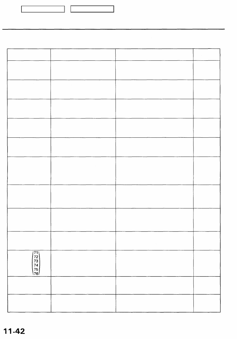
Diagnostic Trouble Code (DTC) Chart (cont'd)
DTC
(MIL indication)
P0139 (63)*
2
P0141 (65)
P0153 (61)*
2
P0154 (1)
P0155 (41)
P0171 (46)*
2
P0172 (46)*
2
P0174 (45)*
2
P0175 (45)*
2
P0300
P0325 (53)
P0330 (23)
Detection Item
Secondary Heated Oxygen Sensor
(Secondary H02S) Slow Response
(Sensor 2)
Secondary Heated Oxygen
Sensor (Secondary HO2S) Heater
Circuit Malfunction (Sensor 2)
Left Primary Heated Oxygen
Sensor (Left Primary HO2S) Slow
Response (Bank 2, Sensor 1)
Left Primary Heated Oxygen
Sensor (Left Primary HO2S)
Heater System Malfunction
Left Primary Heated Oxygen
Sensor (Left Primary H02S)
Heater Circuit Malfunction (Bank
2, Sensor 1)
Fuel System Too Lean [Right
Bank (Bank 1)]
Fuel System Too Rich [Right Bank
(Bank 1)]
Fuel System Too Lean [Left Bank
(Bank 2)]
Fuel System Too Rich [Left Bank
(Bank 2)]
Random Misfire
Right Knock Sensor (Bank 1)
Circuit Malfunction
Left Knock Sensor (Bank 2)
Circuit Malfunction
Probable Cause
• Secondary H02S (Sensor 2)
• Open or short in Secondary H02S
(Sensor 2) heater circuit
• PCM
• Left Primary H02S (Bank 2, Sensor 1)
• Exhaust system
• Open in Left Primary H02S (Bank 2,
Sensor 1) circuit
• Left Primary H02S (Bank 2, Sensor 1)
• PCM
• Open or short in Left Primary HO2S
(Bank 2, Sensor 1) heater circuit
• PCM
• Fuel supply system
• Right Primary H02S (Bank 1, Sensor 1)
• MAP sensor
• Contaminated fuel
• Valve clearance
• Exhaust leakage
• Fuel supply system
• Right Primary HO2S (Bank 1, Sensor 1)
• MAP sensor
• Contaminated fuel
• Valve clearance
• Fuel supply system
• Left Primary H02S (Bank 2, Sensor 1)
• MAP sensor
• Contaminated fuel
• Exhaust leakage
• Fuel supply system
• Left Primary H02S (Bank 2, Sensor 1)
• MAP sensor
• Contaminated fuel
• Ignition system
• Fuel supply system
• MAP sensor
• EGR system
• Contaminated fuel
• Lack of fuel
• Open or short in Right Knock Sensor
(Bank 1) circuit
• Right Knock Sensor (Bank 1)
• PCM
• Open or short in Left Knock Sensor
(Bank 2) circuit
• Left Knock Sensor (Bank 2)
• PCM
Page
*2: These DTCs require two "trips" or two driving cycles unless the SCS service connector is connected.
Main Menu
Table of Contents