Acura RL. Manual - part 206
 

  Index      Acura     Acura RL - service repair manual 2005-2008 year


Search            


Content   ..  204  205  206  207   ..


Acura RL. Manual - part 206


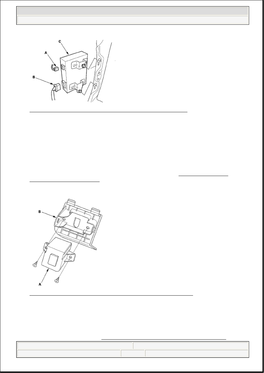
Fig. 111: Identifying 2P Connector, 14P Connector And XM Receiver 
Courtesy of AMERICAN HONDA MOTOR CO., INC. 

3. Loosen the mounting bolts, then pull out the XM receiver.  

4. Install the XM receiver in the reverse order of removal.  

AUXILIARY JACK ASSEMBLY REPLACEMENT 

'07-08 MODELS 

1. Remove the console box mat, screws, and the auxiliary jack trim (see CENTER CONSOLE 

REMOVAL/INSTALLATION ).  

2. Remove the screws and the auxiliary jack assembly (A) from the auxiliary jack trim (B). 

Fig. 112: Identifying Auxiliary Jack Assembly And Auxiliary Jack Trim 
Courtesy of AMERICAN HONDA MOTOR CO., INC. 

3. Install the unit in the reverse order of removal.  

ACTIVE NOISE CONTROL UNIT REMOVAL/INSTALLATION 

1. Remove the stereo amplifier (see STEREO AMPLIFIER REMOVAL/INSTALLATION ). 


2007 Acura RL 

2005-08 ACCESSORIES AND EQUIPMENT Audio System - RL


me 


Friday, June 05, 2009 3:53:08 PM

Page 102  © 2005 Mitchell Repair Information Company, LLC. 

2. Remove the screws and the active noise control unit (A). 

Fig. 113: Identifying Screws And Active Noise Control Unit 
Courtesy of AMERICAN HONDA MOTOR CO., INC. 

3. Install the unit in the reverse order of removal.  

ACTIVE NOISE CONTROL MICROPHONE REMOVAL/INSTALLATION 

1. Remove the headliner (see HEADLINER REMOVAL/INSTALLATION ).  

2. Disconnect the connectors (A), then remove the screws and the active noise control microphone (B). 

Fig. 114: Identifying Active Noise Control Microphone, Cap And Base 
Courtesy of AMERICAN HONDA MOTOR CO., INC. 

3. Remove the cap (C) from the base (D).  

4. Install the microphone in the reverse order of removal.  

AUDIO REMOTE SWITCH TEST


2007 Acura RL 

2005-08 ACCESSORIES AND EQUIPMENT Audio System - RL


me 


Friday, June 05, 2009 3:53:08 PM

Page 103  © 2005 Mitchell Repair Information Company, LLC. 

1. Remove the driver's airbag assembly (see DRIVER'S AIRBAG REPLACEMENT ).  

2. Remove the 20P connector from the cable reel. 

Fig. 115: Identifying Cable Reel 20P Connector 
Courtesy of AMERICAN HONDA MOTOR CO., INC. 

3. Measure the resistance between the No. 7 and No. 8 terminals in each switch position according to the 

table. 

RESISTANCE CHART 

4. If the resistance is not as specified, replace the remote switch.  

5. Use a diode tester between the terminals in each switch position (see Fig. 116). 

Fig. 116: Testing Remote Switch Using Diode Tester Between Terminals In Each Switch 
Position
 
Courtesy of AMERICAN HONDA MOTOR CO., INC. 

6. If the diode test is not as specified, replace the switch. 

Position

Resistance

OFF

About 10 kohms

MODE

About 3.7 kohms

CH (+)

About 1.7 kohms

CH (-)

About 775 ohms

? (VOL. UP)

About 357 ohms

? (VOL. DOWN) About 100 ohms


2007 Acura RL 

2005-08 ACCESSORIES AND EQUIPMENT Audio System - RL


me 


Friday, June 05, 2009 3:53:08 PM

Page 104  © 2005 Mitchell Repair Information Company, LLC. 

AM/FM ANTENNA AMPLIFIER REPLACEMENT

1. Remove the C-pillar trim (see C-PILLAR TRIM ).  

2. Disconnect the connectors (A) from the AM/FM antenna amplifier (B). 

AM/FM main antenna amplifier  

Fig. 117: Identifying Connectors And AM/FM Antenna Amplifier - AM/FM Main Antenna 
Amplifier
 
Courtesy of AMERICAN HONDA MOTOR CO., INC. 

AM/FM subantenna amplifier  

Fig. 118: Identifying Connectors And AM/FM Antenna Amplifier - AM/FM Subantenna 
Amplifier
 
Courtesy of AMERICAN HONDA MOTOR CO., INC. 

3. Remove the bolt and AM/FM antenna amplifier.  

4. Install the unit in the reverse order of removal.  

XM ANTENNA MODULE REPLACEMENT


2007 Acura RL 

2005-08 ACCESSORIES AND EQUIPMENT Audio System - RL


me 


Friday, June 05, 2009 3:53:08 PM

Page 105  © 2005 Mitchell Repair Information Company, LLC. 


Content   ..  204  205  206  207   ..