Acura CSX. Manual - part 396
*01
*02
SNR9AC6D10600000000FAAT04
−
−
−
−
−
−
−
−
ABS indicator and brake system indicator do
not go off
YES
NO
YES
NO
YES
NO
YES
NO
19-88
ABS Components
Symptom Troubleshooting
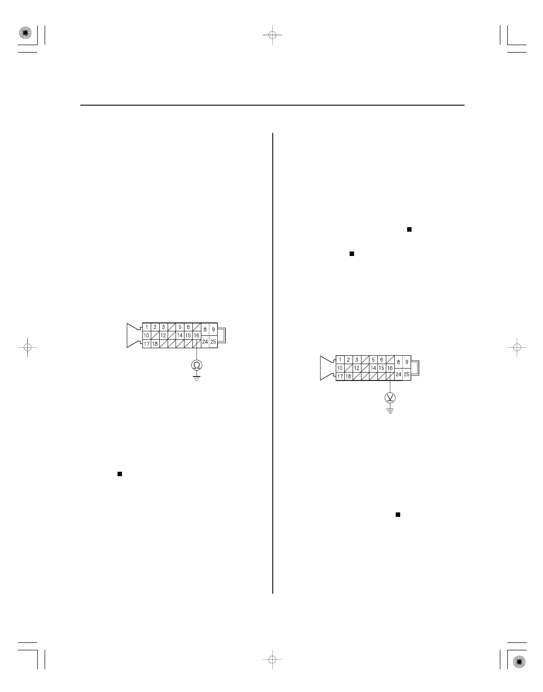
ABS MODULATOR-CONTROL UNIT 25P CONNECTOR
IG1 (YEL)*
*1: ’06 model
*2: ’07 model
(GRY)*
ABS MODULATOR-CONTROL UNIT 25P CONNECTOR
IG1 (YEL)*
*1: ’06 model
*2: ’07 model
(GRY)*
1
2
1
2
1. Turn the ignition switch to LOCK (0).
2. Check the No. 4 (7.5 A) fuse in the under-dash fuse/
relay box.
Go to step 3.
Reinstall the checked fuse, then go to step 8.
3. Disconnect the ABS modulator-control unit 25P
connector (see step 2 on page 19-90).
4. Check for continuity between ABS modulator-
control unit 25P connector terminal No. 16 and
body ground.
Repair short to body ground in the wire
between the No. 4 (7.5 A) fuse in the under-dash
fuse/relay box and the ABS modulator-control
unit.
Install a new No. 4 (7.5 A) fuse in the under-
dash fuse/relay box, then go to step 5.
5. Reconnect the ABS modulator-control unit 25P
connector.
6. Turn the ignition switch to ON (II).
7. Check the ABS indicator and the brake system
indicator for several seconds when the ignition
switch is tuned to ON (II).
Troubleshooting is complete.
Replace the ABS modulator-control unit
(see page 19-90).
8. Disconnect the ABS modulator-control unit 25P
connector (see step 2 on page 19-90).
9. Turn the ignition switch to ON (II).
10. Measure the voltage between ABS modulator-
control unit 25P connector terminal No. 16 and
body ground.
Go to step 11.
Repair open in the wire between the No. 4
(7.5 A) fuse in the under-dash fuse/relay box and
the ABS modulator-control unit.
11. Turn the ignition switch to LOCK (0).
Wire side of female terminals
Wire side of female terminals
Is the f use blown?
Is ther e continuity?
Does the indicator s come on then go of f ?
Is ther e batter y voltage?
08/08/21 15:03:17 61SNR030_190_0088