Acura CSX. Manual - part 344
 

  Index      Acura     Acura CSX - P/NO. 61SNR03 - service repair manual 2006-2009 year


Search            


Content   ..  342  343  344  345   ..


Acura CSX. Manual - part 344


01

02

SNR9A00K722000R5102FAAT01

DTC 51-02:

DTC 51-03:

DTC 51-06:

DTC 51-07:

YES

NO

YES

NO

YES

NO

YES

NO

17-50

EPS Components

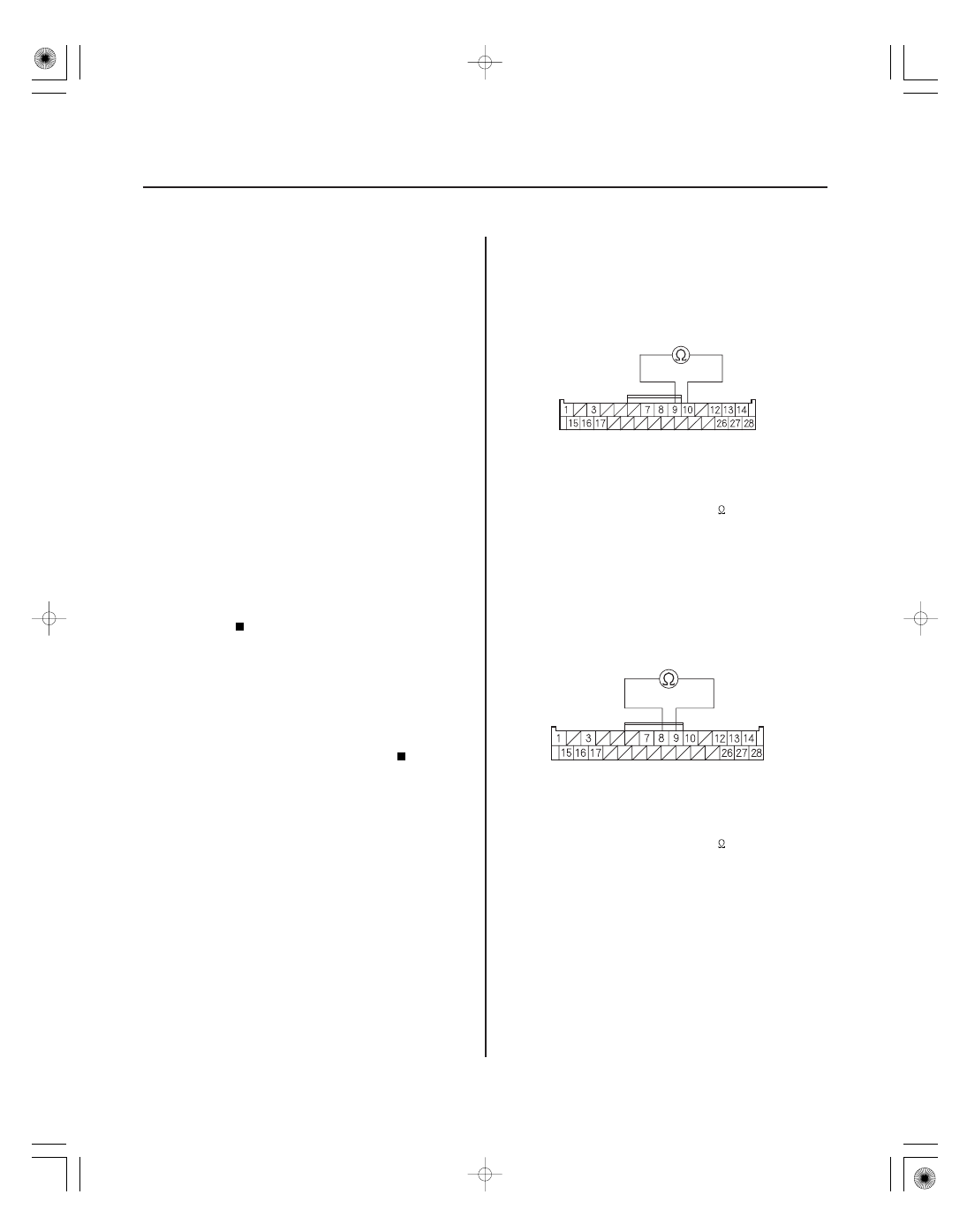
EPS CONTROL UNIT CONNECTOR D (28P)

PVF (BRN)

VS1 (GRN)

EPS CONTROL UNIT CONNECTOR D (28P)

PVF (BRN)

VS2 (LT GRN)

Torque Sensor (VT3 Differential-

amplification Function) (Regular Diagnosis)

Torque Sensor (VT1, VT2 Rapid

Change) (Regular Diagnosis)

Torque Sensor (VT1, VT2

Average) (Regular Diagnosis)

Torque Sensor (VT1, VT2 Initial

Check) (Initial Diagnosis)

1. Turn the ignition switch to ON (II).

2. Clear the DTC with the HDS.

3. Turn the ignition switch to LOCK (0).

4. Start the engine.

Go to step 5.

Check for loose terminals or poor connections.

If the connections are good, the system is OK at
this time.

5. Check for DTCs with the HDS.

Go to step 6.

Troubleshoot the indicated DTC. If there are

no DTCs, the system is OK at this time.

6. Turn the ignition switch to LOCK (0).

7. Disconnect EPS control unit connector D (28P).

8. Measure the resistance between EPS control unit

connector D (28P) terminals No. 9 and No. 10.

Go to step 9.

Go to step 13.

9. Measure the resistance between EPS control unit

connector D (28P) terminals No. 8 and No. 9.

Go to step 10.

Go to step 15.

Wire side of female terminals

Wire side of female terminals

Does the EPS indicator come on?

Is DT C 51-02, 51-03, 51-06, or 51-07 indicated?

Is the r esistance between 12

15

?

Is the r esistance between 12

15

?

08/08/21 14:54:35 61SNR030_170_0051

03

01

YES

NO

YES

NO

17-51

EPS CONTROL UNIT CONNECTOR D (28P)

PVF (BRN)

EPS CONTROL UNIT CONNECTOR D (28P)

PVF (BRN)

10. Check for continuity between EPS control unit

connector D (28P) terminal No. 9 and body ground.

Go to step 11.

Check for loose terminals in the EPS control

unit connectors, and repair if necessary. If no poor
connections are found, replace the EPS control unit
(see page 17-84).

11. Disconnect the torque sensor 3P connector from

the steering gearbox.

12. Check for continuity between EPS control unit

connector D (28P) terminal No. 9 and body ground.

Repair short to body ground in the wire

between the torque sensor and the EPS control
unit.

Faulty torque sensor (short in the sensor

internal circuit), replace the steering gearbox
(see page 17-65).

Wire side of female terminals

Wire side of female terminals

Is ther e continuity?

Is ther e continuity?

08/08/21 14:54:36 61SNR030_170_0052

05

06

YES

NO

YES

NO

17-52

EPS Components

TORQUE SENSOR 3P CONNECTOR

VS1

PVF

TORQUE SENSOR 3P CONNECTOR

VS2

PVF

13. Disconnect the torque sensor 3P connector from

the steering gearbox.

14. On the sensor side, measure the resistance

between torque sensor 3P connector terminals
No. 1 and No. 2.

Repair open or short between the PNK and

BLU/RED wires in the torque sensor circuit between
the torque sensor and the EPS control unit.

Faulty torque sensor (short or open in the

internal circuit), replace the steering gearbox
(see page 17-65).

15. Disconnect the torque sensor 3P connector from

the steering gearbox.

16. On the sensor side, measure the resistance

between torque sensor 3P connector terminals
No. 2 and No. 3.

Repair open or short between the BLU/RED

and WHT/GRN wires in the torque sensor circuit
between the torque sensor and the EPS control
unit.

Faulty torque sensor (short or open in the

internal circuit), replace the steering gearbox
(see page 17-65).

Terminal side of male terminals

Terminal side of male terminals

Is the r esistance between 12

15

?

Is the r esistance between 12

15

?

08/08/21 14:54:36 61SNR030_170_0053

*01

SNR9A00K722000R6104FAAT00

DTC 61-04:

YES

NO

YES

NO

YES

NO

17-53

EPS CONTROL UNIT
CONNECTOR B

EPS CONTROL UNIT
CONNECTOR C

No. 1
No. 2
No. 1
No. 2

No. 1
No. 1

EPS CONTROL UNIT CONNECTOR B (2P)

H-V (BLU)

H-U (RED)

H-W (GRN)

EPS CONTROL UNIT CONNECTOR C (2P)

Open/Short in EPS Motor Harness

(Steering Diagnosis)

1. Turn the ignition switch to ON (II).

2. Clear the DTC with the HDS.

3. Turn the ignition switch to LOCK (0).

4. Start the engine.

5. Turn the steering wheel to the right or left, and wait

10 seconds or more.

Go to step 6.

Check for loose terminals or poor connections.

If the connections are good, the system is OK at
this time.

6. Check for DTCs with the HDS.

Go to step 7.

Troubleshoot the indicated DTC. If there are

no DTCs, the system is OK at this time.

7. Turn the ignition switch to LOCK (0).

8. Disconnect the EPS control unit connector B (2P)

and connector C (2P).

9. Check for continuity between the following

terminals of the EPS control unit connector B (2P)
and connector C (2P).

Go to step 10.

Go to step 13.

Wire side of female terminals

Wire side of female terminals

Does the EPS indicator come on?

Is DT C 61-04 indicated?

Is ther e continuity?

08/08/21 14:54:36 61SNR030_170_0054


Content   ..  342  343  344  345   ..