Intel 64 and IA-32 Architectures. Software Developer’s Manual (Collection, 2023) - page 113

Intel® 64 and IA-32 Architectures
Software Developer’s Manual
Volume 3C:
System Programming Guide, Part 3
NOTE: The Intel® 64 and IA-32 Architectures Software Developer's Manual consists of ten volumes:
Basic Architecture, Order Number 253665; Instruction Set Reference, A-L, Order Number 253666;
Instruction Set Reference, M-U, Order Number 253667; Instruction Set Reference, V, Order Number
326018; Instruction Set Reference, W-Z, Order Number 334569; System Programming Guide, Part 1,
Order Number
253668; System Programming Guide, Part
2, Order Number
253669; System
Programming Guide, Part 3, Order Number 326019; System Programming Guide, Part 4, Order Number
332831; Model-Specific Registers, Order Number 335592. Refer to all ten volumes when evaluating
your design needs.
Order Number: 326019-082US
December 2023

CHAPTER 24
INTRODUCTION TO VIRTUAL MACHINE EXTENSIONS
24.1
OVERVIEW
This chapter describes the basics of virtual machine architecture and an overview of the virtual-machine extensions
(VMX) that support virtualization of processor hardware for multiple software environments.
Information about VMX instructions is provided in the Intel® 64 and IA-32 Architectures Software Developer’s
Manual, Volume 2B. Other aspects of VMX and system programming considerations are described in chapters of
Intel® 64 and IA-32 Architectures Software Developer’s Manual, Volume 3C.
24.2
VIRTUAL MACHINE ARCHITECTURE
Virtual-machine extensions define processor-level support for virtual machines on IA-32 processors. Two principal
classes of software are supported:
• Virtual-machine monitors (VMM) — A VMM acts as a host and has full control of the processor(s) and other
platform hardware. A VMM presents guest software (see next paragraph) with an abstraction of a virtual
processor and allows it to execute directly on a logical processor. A VMM is able to retain selective control of
processor resources, physical memory, interrupt management, and I/O.
• Guest software — Each virtual machine (VM) is a guest software environment that supports a stack consisting
of operating system (OS) and application software. Each operates independently of other virtual machines and
uses on the same interface to processor(s), memory, storage, graphics, and I/O provided by a physical
platform. The software stack acts as if it were running on a platform with no VMM. Software executing in a
virtual machine must operate with reduced privilege so that the VMM can retain control of platform resources.
24.3
INTRODUCTION TO VMX OPERATION
Processor support for virtualization is provided by a form of processor operation called VMX operation. There are
two kinds of VMX operation: VMX root operation and VMX non-root operation. In general, a VMM will run in VMX
root operation and guest software will run in VMX non-root operation. Transitions between VMX root operation and
VMX non-root operation are called VMX transitions. There are two kinds of VMX transitions. Transitions into VMX
non-root operation are called VM entries. Transitions from VMX non-root operation to VMX root operation are called
VM exits.
Processor behavior in VMX root operation is very much as it is outside VMX operation. The principal differences are
that a set of new instructions (the VMX instructions) is available and that the values that can be loaded into certain
control registers are limited (see Section 24.8).
Processor behavior in VMX non-root operation is restricted and modified to facilitate virtualization. Instead of their
ordinary operation, certain instructions (including the new VMCALL instruction) and events cause VM exits to the
VMM. Because these VM exits replace ordinary behavior, the functionality of software in VMX non-root operation is
limited. It is this limitation that allows the VMM to retain control of processor resources.
There is no software-visible bit whose setting indicates whether a logical processor is in VMX non-root operation.
This fact may allow a VMM to prevent guest software from determining that it is running in a virtual machine.
Because VMX operation places restrictions even on software running with current privilege level (CPL) 0, guest
software can run at the privilege level for which it was originally designed. This capability may simplify the devel-
opment of a VMM.
Vol. 3C
24-1
INTRODUCTION TO VIRTUAL MACHINE EXTENSIONS
24.4
LIFE CYCLE OF VMM SOFTWARE
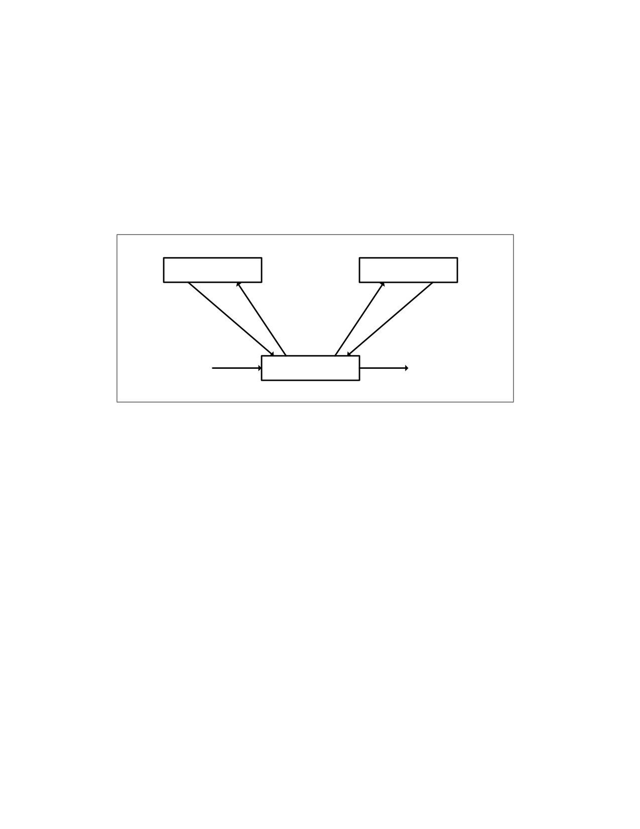
Figure 24-1 illustrates the life cycle of a VMM and its guest software as well as the interactions between them. The
following items summarize that life cycle:
• Software enters VMX operation by executing a VMXON instruction.
• Using VM entries, a VMM can then enter guests into virtual machines (one at a time). The VMM effects a
VM entry using instructions VMLAUNCH and VMRESUME; it regains control using VM exits.
• VM exits transfer control to an entry point specified by the VMM. The VMM can take action appropriate to the
cause of the VM exit and can then return to the virtual machine using a VM entry.
• Eventually, the VMM may decide to shut itself down and leave VMX operation. It does so by executing the
VMXOFF instruction.
Guest 0
Guest 1
VM Entry
VM Exit
VM Exit
VMXON
VM Monitor
VMXOFF
Figure 24-1. Interaction of a Virtual-Machine Monitor and Guests
24.5
VIRTUAL-MACHINE CONTROL STRUCTURE
VMX non-root operation and VMX transitions are controlled by a data structure called a virtual-machine control
structure (VMCS).
Access to the VMCS is managed through a component of processor state called the VMCS pointer (one per logical
processor). The value of the VMCS pointer is the 64-bit address of the VMCS. The VMCS pointer is read and written
using the instructions VMPTRST and VMPTRLD. The VMM configures a VMCS using the VMREAD, VMWRITE, and
VMCLEAR instructions.
A VMM could use a different VMCS for each virtual machine that it supports. For a virtual machine with multiple
logical processors (virtual processors), the VMM could use a different VMCS for each virtual processor.
24.6
DISCOVERING SUPPORT FOR VMX
Before system software enters into VMX operation, it must discover the presence of VMX support in the processor.
System software can determine whether a processor supports VMX operation using CPUID. If
CPUID.1:ECX.VMX[bit 5] = 1, then VMX operation is supported. See Chapter 3, “Instruction Set Reference, A-L‚” of
the Intel® 64 and IA-32 Architectures Software Developer’s Manual, Volume 2A.
The VMX architecture is designed to be extensible so that future processors in VMX operation can support addi-
tional features not present in first-generation implementations of the VMX architecture. The availability of exten-
sible VMX features is reported to software using a set of VMX capability MSRs (see Appendix A, “VMX Capability
Reporting Facility”).
24-2
Vol. 3C

INTRODUCTION TO VIRTUAL MACHINE EXTENSIONS
24.7
ENABLING AND ENTERING VMX OPERATION
Before system software can enter VMX operation, it enables VMX by setting CR4.VMXE[bit 13] = 1. VMX operation
is then entered by executing the VMXON instruction. VMXON causes an invalid-opcode exception (#UD) if executed
with CR4.VMXE = 0. Once in VMX operation, it is not possible to clear CR4.VMXE (see Section 24.8). System soft-
ware leaves VMX operation by executing the VMXOFF instruction. CR4.VMXE can be cleared outside of VMX opera-
tion after executing of VMXOFF.
VMXON is also controlled by the IA32_FEATURE_CONTROL MSR (MSR address 3AH). This MSR is cleared to zero
when a logical processor is reset. The relevant bits of the MSR are:
• Bit 0 is the lock bit. If this bit is clear, VMXON causes a general-protection exception. If the lock bit is set,
WRMSR to this MSR causes a general-protection exception; the MSR cannot be modified until a power-up reset
condition. System BIOS can use this bit to provide a setup option for BIOS to disable support for VMX. To
enable VMX support in a platform, BIOS must set bit 1, bit 2, or both (see below), as well as the lock bit.
• Bit 1 enables VMXON in SMX operation. If this bit is clear, execution of VMXON in SMX operation causes a
general-protection exception. Attempts to set this bit on logical processors that do not support both VMX
operation (see Section 24.6) and SMX operation (see Chapter 7, “Safer Mode Extensions Reference,” in the
Intel® 64 and IA-32 Architectures Software Developer’s Manual, Volume 2D) cause general-protection
exceptions.
• Bit 2 enables VMXON outside SMX operation. If this bit is clear, execution of VMXON outside SMX
operation causes a general-protection exception. Attempts to set this bit on logical processors that do not
support VMX operation (see Section 24.6) cause general-protection exceptions.
NOTE
A logical processor is in SMX operation if GETSEC[SEXIT] has not been executed since the last
execution of GETSEC[SENTER]. A logical processor is outside SMX operation if GETSEC[SENTER]
has not been executed or if GETSEC[SEXIT] was executed after the last execution of
GETSEC[SENTER]. See Chapter 7, “Safer Mode Extensions Reference,” in Intel® 64 and IA-32
Architectures Software Developer’s Manual, Volume 2D.
Before executing VMXON, software should allocate a naturally aligned 4-KByte region of memory that a logical
processor may use to support VMX operation.1 This region is called the VMXON region. The address of the VMXON
region (the VMXON pointer) is provided in an operand to VMXON. Section 25.11.5, “VMXON Region,” details how
software should initialize and access the VMXON region.
24.8
RESTRICTIONS ON VMX OPERATION
VMX operation places restrictions on processor operation. These are detailed below:
• In VMX operation, processors may fix certain bits in CR0 and CR4 to specific values and not support other
values. VMXON fails if any of these bits contains an unsupported value (see “VMXON—Enter VMX Operation” in
Chapter 31). Any attempt to set one of these bits to an unsupported value while in VMX operation (including
VMX root operation) using any of the CLTS, LMSW, or MOV CR instructions causes a general-protection
exception. VM entry or VM exit cannot set any of these bits to an unsupported value. Software should consult
the VMX capability MSRs IA32_VMX_CR0_FIXED0 and IA32_VMX_CR0_FIXED1 to determine how bits in CR0
are fixed (see Appendix A.7). For CR4, software should consult the VMX capability MSRs
IA32_VMX_CR4_FIXED0 and IA32_VMX_CR4_FIXED1 (see Appendix A.8).
NOTES
The first processors to support VMX operation require that the following bits be 1 in VMX operation:
CR0.PE, CR0.NE, CR0.PG, and CR4.VMXE. The restrictions on CR0.PE and CR0.PG imply that VMX
1. Future processors may require that a different amount of memory be reserved. If so, this fact is reported to software using the
VMX capability-reporting mechanism.
Vol. 3C
24-3

INTRODUCTION TO VIRTUAL MACHINE EXTENSIONS
operation is supported only in paged protected mode (including IA-32e mode). Therefore, guest
software cannot be run in unpaged protected mode or in real-address mode.
Later processors support a VM-execution control called “unrestricted guest” (see Section 25.6.2).
If this control is 1, CR0.PE and CR0.PG may be 0 in VMX non-root operation (even if the capability
MSR IA32_VMX_CR0_FIXED0 reports otherwise).1 Such processors allow guest software to run in
unpaged protected mode or in real-address mode.
• VMXON fails if a logical processor is in A20M mode (see “VMXON—Enter VMX Operation” in Chapter 31). Once
the processor is in VMX operation, A20M interrupts are blocked. Thus, it is impossible to be in A20M mode in
VMX operation.
• The INIT signal is blocked whenever a logical processor is in VMX root operation. It is not blocked in VMX non-
root operation. Instead, INITs cause VM exits (see Section 26.2, “Other Causes of VM Exits”).
• Intel® Processor Trace (Intel PT) can be used in VMX operation only if IA32_VMX_MISC[14] is read as 1 (see
Appendix A.6). On processors that support Intel PT but which do not allow it to be used in VMX operation,
execution of VMXON clears IA32_RTIT_CTL.TraceEn (see “VMXON—Enter VMX Operation” in Chapter 31); any
attempt to write IA32_RTIT_CTL while in VMX operation (including VMX root operation) causes a general-
protection exception.
1.
“Unrestricted guest” is a secondary processor-based VM-execution control. If bit 31 of the primary processor-based VM-execution
controls is 0, VMX non-root operation functions as if the “unrestricted guest” VM-execution control were 0. See Section 25.6.2.
24-4
Vol. 3C

CHAPTER 25
VIRTUAL MACHINE CONTROL STRUCTURES
25.1
OVERVIEW
A logical processor uses virtual-machine control data structures (VMCSs) while it is in VMX operation. These
manage transitions into and out of VMX non-root operation (VM entries and VM exits) as well as processor behavior
in VMX non-root operation. This structure is manipulated by the new instructions VMCLEAR, VMPTRLD, VMREAD,
and VMWRITE.
A VMM can use a different VMCS for each virtual machine that it supports. For a virtual machine with multiple
logical processors (virtual processors), the VMM can use a different VMCS for each virtual processor.
A logical processor associates a region in memory with each VMCS. This region is called the VMCS region.1 Soft-
ware references a specific VMCS using the 64-bit physical address of the region (a VMCS pointer). VMCS pointers
must be aligned on a 4-KByte boundary (bits 11:0 must be zero). These pointers must not set bits beyond the
processor’s physical-address width.2,3
A logical processor may maintain a number of VMCSs that are active. The processor may optimize VMX operation
by maintaining the state of an active VMCS in memory, on the processor, or both. At any given time, at most one
of the active VMCSs is the current VMCS. (This document frequently uses the term “the VMCS” to refer to the
current VMCS.) The VMLAUNCH, VMREAD, VMRESUME, and VMWRITE instructions operate only on the current
VMCS.
The following items describe how a logical processor determines which VMCSs are active and which is current:
• The memory operand of the VMPTRLD instruction is the address of a VMCS. After execution of the instruction,
that VMCS is both active and current on the logical processor. Any other VMCS that had been active remains so,
but no other VMCS is current.
• The VMCS link pointer field in the current VMCS (see Section 25.4.2) is itself the address of a VMCS. If VM entry
is performed successfully with the 1-setting of the “VMCS shadowing” VM-execution control, the VMCS
referenced by the VMCS link pointer field becomes active on the logical processor. The identity of the current
VMCS does not change.
• The memory operand of the VMCLEAR instruction is also the address of a VMCS. After execution of the
instruction, that VMCS is neither active nor current on the logical processor. If the VMCS had been current on
the logical processor, the logical processor no longer has a current VMCS.
The VMPTRST instruction stores the address of the logical processor’s current VMCS into a specified memory loca-
tion (it stores the value FFFFFFFF_FFFFFFFFH if there is no current VMCS).
The launch state of a VMCS determines which VM-entry instruction should be used with that VMCS: the
VMLAUNCH instruction requires a VMCS whose launch state is “clear”; the VMRESUME instruction requires a VMCS
whose launch state is “launched”. A logical processor maintains a VMCS’s launch state in the corresponding VMCS
region. The following items describe how a logical processor manages the launch state of a VMCS:
• If the launch state of the current VMCS is “clear”, successful execution of the VMLAUNCH instruction changes
the launch state to “launched”.
• The memory operand of the VMCLEAR instruction is the address of a VMCS. After execution of the instruction,
the launch state of that VMCS is “clear”.
• There are no other ways to modify the launch state of a VMCS (it cannot be modified using VMWRITE) and there
is no direct way to discover it (it cannot be read using VMREAD).
1. The amount of memory required for a VMCS region is at most 4 KBytes. The exact size is implementation specific and can be deter-
mined by consulting the VMX capability MSR IA32_VMX_BASIC to determine the size of the VMCS region (see Appendix A.1).
2. Software can determine a processor’s physical-address width by executing CPUID with 80000008H in EAX. The physical-address
width is returned in bits 7:0 of EAX.
3. If IA32_VMX_BASIC[48] is read as 1, these pointers must not set any bits in the range 63:32; see Appendix A.1.
Vol. 3C
25-1
VIRTUAL MACHINE CONTROL STRUCTURES
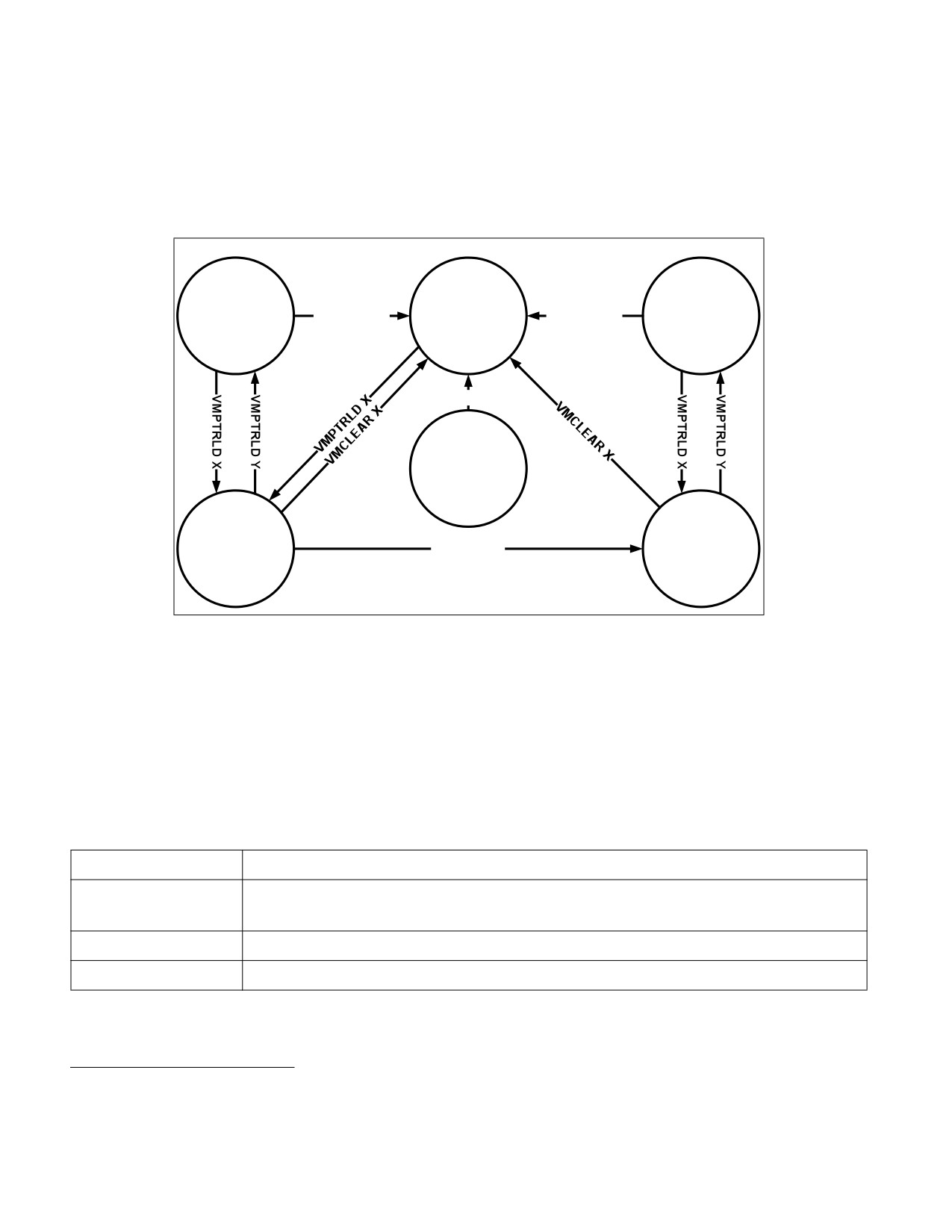
Figure 25-1 illustrates the different states of a VMCS. It uses “X” to refer to the VMCS and “Y” to refer to any other
VMCS. Thus: “VMPTRLD X” always makes X current and active; “VMPTRLD Y” always makes X not current (because
it makes Y current); VMLAUNCH makes the launch state of X “launched” if X was current and its launch state was
“clear”; and VMCLEAR X always makes X inactive and not current and makes its launch state “clear”.
The figure does not illustrate operations that do not modify the VMCS state relative to these parameters (e.g.,
execution of VMPTRLD X when X is already current). Note that VMCLEAR X makes X “inactive, not current, and
clear,” even if X’s current state is not defined (e.g., even if X has not yet been initialized). See Section 25.11.3.
Active
Inactive
Active
Not Current
VMCLEAR X
Not Current
VMCLEAR X
Not Current
Clear
Clear
Launched
VMCLEAR X
Anything
Else
Active
Active
Current
VMLAUNCH
Current
Clear
Launched
Figure 25-1. States of VMCS X
Because a shadow VMCS (see Section 25.10) cannot be used for VM entry, the launch state of a shadow VMCS is
not meaningful. Figure 25-1 does not illustrate all the ways in which a shadow VMCS may be made active.
25.2
FORMAT OF THE VMCS REGION
A VMCS region comprises up to 4-KBytes.1 The format of a VMCS region is given in Table 25-1.
Table 25-1. Format of the VMCS Region
Byte Offset
Contents
0
Bits 30:0: VMCS revision identifier
Bit 31: shadow-VMCS indicator (see Section 25.10)
4
VMX-abort indicator
8
VMCS data (implementation-specific format)
1. The exact size is implementation specific and can be determined by consulting the VMX capability MSR IA32_VMX_BASIC to deter-
mine the size of the VMCS region (see Appendix A.1).
25-2
Vol. 3C

VIRTUAL MACHINE CONTROL STRUCTURES
The first 4 bytes of the VMCS region contain the VMCS revision identifier at bits 30:0.1 Processors that maintain
VMCS data in different formats (see below) use different VMCS revision identifiers. These identifiers enable soft-
ware to avoid using a VMCS region formatted for one processor on a processor that uses a different format.2 Bit 31
of this 4-byte region indicates whether the VMCS is a shadow VMCS (see Section 25.10).
Software should write the VMCS revision identifier to the VMCS region before using that region for a VMCS. The
VMCS revision identifier is never written by the processor; VMPTRLD fails if its operand references a VMCS region
whose VMCS revision identifier differs from that used by the processor. (VMPTRLD also fails if the shadow-VMCS
indicator is 1 and the processor does not support the 1-setting of the “VMCS shadowing” VM-execution control; see
Section 25.6.2) Software can discover the VMCS revision identifier that a processor uses by reading the VMX capa-
bility MSR IA32_VMX_BASIC (see Appendix A.1).
Software should clear or set the shadow-VMCS indicator depending on whether the VMCS is to be an ordinary
VMCS or a shadow VMCS (see Section 25.10). VMPTRLD fails if the shadow-VMCS indicator is set and the processor
does not support the 1-setting of the “VMCS shadowing” VM-execution control. Software can discover support for
this setting by reading the VMX capability MSR IA32_VMX_PROCBASED_CTLS2 (see Appendix A.3.3).
The next 4 bytes of the VMCS region are used for the VMX-abort indicator. The contents of these bits do not
control processor operation in any way. A logical processor writes a non-zero value into these bits if a VMX abort
occurs (see Section 28.7). Software may also write into this field.
The remainder of the VMCS region is used for VMCS data (those parts of the VMCS that control VMX non-root
operation and the VMX transitions). The format of these data is implementation-specific. VMCS data are discussed
in Section 25.3 through Section 25.9. To ensure proper behavior in VMX operation, software should maintain the
VMCS region and related structures (enumerated in Section 25.11.4) in writeback cacheable memory. Future
implementations may allow or require a different memory type3. Software should consult the VMX capability MSR
IA32_VMX_BASIC (see Appendix A.1).
25.3
ORGANIZATION OF VMCS DATA
The VMCS data are organized into six logical groups:
• Guest-state area. Processor state is saved into the guest-state area on VM exits and loaded from there on
VM entries.
• Host-state area. Processor state is loaded from the host-state area on VM exits.
• VM-execution control fields. These fields control processor behavior in VMX non-root operation. They
determine in part the causes of VM exits.
• VM-exit control fields. These fields control VM exits.
• VM-entry control fields. These fields control VM entries.
• VM-exit information fields. These fields receive information on VM exits and describe the cause and the
nature of VM exits. On some processors, these fields are read-only.4
The VM-execution control fields, the VM-exit control fields, and the VM-entry control fields are sometimes referred
to collectively as VMX controls.
1. Earlier versions of this manual specified that the VMCS revision identifier was a 32-bit field. For all processors produced prior to this
change, bit 31 of the VMCS revision identifier was 0.
2. Logical processors that use the same VMCS revision identifier use the same size for VMCS regions.
3. Alternatively, software may map any of these regions or structures with the UC memory type. Doing so is strongly discouraged
unless necessary as it will cause the performance of transitions using those structures to suffer significantly. In addition, the pro-
cessor will continue to use the memory type reported in the VMX capability MSR IA32_VMX_BASIC with exceptions noted in Appen-
dix A.1.
4. Software can discover whether these fields can be written by reading the VMX capability MSR IA32_VMX_MISC (see Appendix A.6).
Vol. 3C
25-3

VIRTUAL MACHINE CONTROL STRUCTURES
25.4
GUEST-STATE AREA
This section describes fields contained in the guest-state area of the VMCS. VM entries load processor state from
these fields and VM exits store processor state into these fields. See Section 27.3.2 and Section 28.3 for details.
25.4.1 Guest Register State
The following fields in the guest-state area correspond to processor registers:
• Control registers CR0, CR3, and CR4 (64 bits each; 32 bits on processors that do not support Intel 64 archi-
tecture).
• Debug register DR7 (64 bits; 32 bits on processors that do not support Intel 64 architecture).
• RSP, RIP, and RFLAGS (64 bits each; 32 bits on processors that do not support Intel 64 architecture).1
• The following fields for each of the registers CS, SS, DS, ES, FS, GS, LDTR, and TR:
— Selector (16 bits).
— Base address (64 bits; 32 bits on processors that do not support Intel 64 architecture). The base-address
fields for CS, SS, DS, and ES have only 32 architecturally-defined bits; nevertheless, the corresponding
VMCS fields have 64 bits on processors that support Intel 64 architecture.
— Segment limit (32 bits). The limit field is always a measure in bytes.
— Access rights (32 bits). The format of this field is given in Table 25-2 and detailed as follows:
• The low 16 bits correspond to bits 23:8 of the upper 32 bits of a 64-bit segment descriptor. While bits
19:16 of code-segment and data-segment descriptors correspond to the upper 4 bits of the segment
limit, the corresponding bits (bits 11:8) are reserved in this VMCS field.
• Bit 16 indicates an unusable segment. Attempts to use such a segment fault except in 64-bit mode.
In general, a segment register is unusable if it has been loaded with a null selector.2
• Bits 31:17 are reserved.
Table 25-2. Format of Access Rights
Bit Position(s)
Field
3:0
Segment type
4
S — Descriptor type (0 = system; 1 = code or data)
6:5
DPL — Descriptor privilege level
7
P — Segment present
11:8
Reserved
12
AVL — Available for use by system software
1. This chapter uses the notation RAX, RIP, RSP, RFLAGS, etc. for processor registers because most processors that support VMX oper-
ation also support Intel 64 architecture. For processors that do not support Intel 64 architecture, this notation refers to the 32-bit
forms of those registers (EAX, EIP, ESP, EFLAGS, etc.). In a few places, notation such as EAX is used to refer specifically to lower 32
bits of the indicated register.
2. There are a few exceptions to this statement. For example, a segment with a non-null selector may be unusable following a task
switch that fails after its commit point; see “Interrupt 10—Invalid TSS Exception (#TS)” in Section 6.14, “Exception and Interrupt
Handling in 64-bit Mode,” of the Intel® 64 and IA-32 Architectures Software Developer’s Manual, Volume 3A. In contrast, the TR reg-
ister is usable after processor reset despite having a null selector; see Table 11-1 in the Intel® 64 and IA-32 Architectures Software
Developer’s Manual, Volume 3A.
25-4
Vol. 3C

VIRTUAL MACHINE CONTROL STRUCTURES
Table 25-2. Format of Access Rights (Contd.)
Bit Position(s)
Field
13
Reserved (except for CS)
L — 64-bit mode active (for CS only)
14
D/B — Default operation size (0 = 16-bit segment; 1 = 32-bit segment)
15
G — Granularity
16
Segment unusable (0 = usable; 1 = unusable)
31:17
Reserved
The base address, segment limit, and access rights compose the “hidden” part (or “descriptor cache”) of each
segment register. These data are included in the VMCS because it is possible for a segment register’s descriptor
cache to be inconsistent with the segment descriptor in memory (in the GDT or the LDT) referenced by the
segment register’s selector.
The value of the DPL field for SS is always equal to the logical processor’s current privilege level (CPL).1
On some processors, executions of VMWRITE ignore attempts to write non-zero values to any of bits 11:8 or
bits 31:17. On such processors, VMREAD always returns 0 for those bits, and VM entry treats those bits as if
they were all 0 (see Section 27.3.1.2).
•
The following fields for each of the registers GDTR and IDTR:
— Base address (64 bits; 32 bits on processors that do not support Intel 64 architecture).
— Limit (32 bits). The limit fields contain 32 bits even though these fields are specified as only 16 bits in the
architecture.
•
The following MSRs:
— IA32_DEBUGCTL (64 bits)
— IA32_SYSENTER_CS (32 bits)
— IA32_SYSENTER_ESP and IA32_SYSENTER_EIP (64 bits; 32 bits on processors that do not support Intel 64
architecture)
— IA32_PERF_GLOBAL_CTRL (64 bits). This field is supported only on processors that support the 1-setting
of the “load IA32_PERF_GLOBAL_CTRL” VM-entry control.
— IA32_PAT (64 bits). This field is supported only on processors that support either the 1-setting of the “load
IA32_PAT” VM-entry control or that of the “save IA32_PAT” VM-exit control.
— IA32_EFER (64 bits). This field is supported only on processors that support either the 1-setting of the “load
IA32_EFER” VM-entry control or that of the “save IA32_EFER” VM-exit control.
— IA32_BNDCFGS (64 bits). This field is supported only on processors that support either the 1-setting of the
“load IA32_BNDCFGS” VM-entry control or that of the “clear IA32_BNDCFGS” VM-exit control.
— IA32_RTIT_CTL (64 bits). This field is supported only on processors that support either the 1-setting of the
“load IA32_RTIT_CTL” VM-entry control or that of the “clear IA32_RTIT_CTL” VM-exit control.
— IA32_LBR_CTL (64 bits). This field is supported only on processors that support either the 1-setting of the
“load guest IA32_LBR_CTL” VM-entry control or that of the “clear IA32_LBR_CTL” VM-exit control.
— IA32_S_CET (64 bits; 32 bits on processors that do not support Intel 64 architecture). This field is
supported only on processors that support the 1-setting of the “load CET state” VM-entry control.
— IA32_INTERRUPT_SSP_TABLE_ADDR (64 bits; 32 bits on processors that do not support Intel 64 archi-
tecture). This field is supported only on processors that support the 1-setting of the “load CET state” VM-
entry control.
1.
In protected mode, CPL is also associated with the RPL field in the CS selector. However, the RPL fields are not meaningful in real-
address mode or in virtual-8086 mode.
Vol. 3C
25-5

VIRTUAL MACHINE CONTROL STRUCTURES
— IA32_PKRS (64 bits). This field is supported only on processors that support the 1-setting of the “load
PKRS” VM-entry control.
• The shadow-stack pointer register SSP (64 bits; 32 bits on processors that do not support Intel 64 archi-
tecture). This field is supported only on processors that support the 1-setting of the “load CET state” VM-entry
control.
• The register SMBASE (32 bits). This register contains the base address of the logical processor’s SMRAM image.
25.4.2 Guest Non-Register State
In addition to the register state described in Section 25.4.1, the guest-state area includes the following fields that
characterize guest state but which do not correspond to processor registers:
• Activity state (32 bits). This field identifies the logical processor’s activity state. When a logical processor is
executing instructions normally, it is in the active state. Execution of certain instructions and the occurrence
of certain events may cause a logical processor to transition to an inactive state in which it ceases to execute
instructions.
The following activity states are defined:1
— 0: Active. The logical processor is executing instructions normally.
— 1: HLT. The logical processor is inactive because it executed the HLT instruction.
— 2: Shutdown. The logical processor is inactive because it incurred a triple fault2 or some other serious
error.
— 3: Wait-for-SIPI. The logical processor is inactive because it is waiting for a startup-IPI (SIPI).
Future processors may include support for other activity states. Software should read the VMX capability MSR
IA32_VMX_MISC (see Appendix A.6) to determine what activity states are supported.
• Interruptibility state (32 bits). The IA-32 architecture includes features that permit certain events to be
blocked for a period of time. This field contains information about such blocking. Details and the format of this
field are given in Table 25-3.
Table 25-3. Format of Interruptibility State
Bit
Bit Name
Notes
Position(s)
0
Blocking by STI
See the “STI—Set Interrupt Flag” section in Chapter 4 of the Intel® 64 and IA-32 Architectures
Software Developer’s Manual, Volume 2B.
Execution of STI with RFLAGS.IF = 0 blocks maskable interrupts on the instruction boundary
following its execution.1 Setting this bit indicates that this blocking is in effect.
1
Blocking by
See Section 6.8.3, “Masking Exceptions and Interrupts When Switching Stacks,” in the Intel® 64
MOV SS
and IA-32 Architectures Software Developer’s Manual, Volume 3A.
Execution of a MOV to SS or a POP to SS blocks or suppresses certain debug exceptions as well
as interrupts (maskable and nonmaskable) on the instruction boundary following its execution.
Setting this bit indicates that this blocking is in effect.2 This document uses the term “blocking
by MOV SS,” but it applies equally to POP SS.
2
Blocking by SMI
See Section 32.2, “System Management Interrupt (SMI).” System-management interrupts
(SMIs) are disabled while the processor is in system-management mode (SMM). Setting this bit
indicates that blocking of SMIs is in effect.
1. Execution of the MWAIT instruction may put a logical processor into an inactive state. However, this VMCS field never reflects this
state. See Section 28.1.
2. A triple fault occurs when a logical processor encounters an exception while attempting to deliver a double fault.
25-6
Vol. 3C

VIRTUAL MACHINE CONTROL STRUCTURES
Table 25-3. Format of Interruptibility State (Contd.)
Bit
Bit Name
Notes
Position(s)
3
Blocking by NMI
See Section 6.7.1, “Handling Multiple NMIs,” in the Intel® 64 and IA-32 Architectures Software
Developer’s Manual, Volume 3A and Section 32.8, “NMI Handling While in SMM.”
Delivery of a non-maskable interrupt (NMI) or a system-management interrupt (SMI) blocks
subsequent NMIs until the next execution of IRET. See Section 26.3 for how this behavior of
IRET may change in VMX non-root operation. Setting this bit indicates that blocking of NMIs is
in effect. Clearing this bit does not imply that NMIs are not (temporarily) blocked for other
reasons.
If the “virtual NMIs” VM-execution control (see Section 25.6.1) is 1, this bit does not control the
blocking of NMIs. Instead, it refers to “virtual-NMI blocking” (the fact that guest software is not
ready for an NMI).
4
Enclave
Set to 1 if the VM exit occurred while the logical processor was in enclave mode.
interruption
Such VM exits includes those caused by interrupts, non-maskable interrupts, system-
management interrupts, INIT signals, and exceptions occurring in enclave mode as well as
exceptions encountered during the delivery of such events incident to enclave mode.
A VM exit that is incident to delivery of an event injected by VM entry leaves this bit
unmodified.
31:5
Reserved
VM entry will fail if these bits are not 0. See Section 27.3.1.5.
NOTES:
1. Nonmaskable interrupts and system-management interrupts may also be inhibited on the instruction boundary following such an
execution of STI.
2. System-management interrupts may also be inhibited on the instruction boundary following such an execution of MOV or POP.
• Pending debug exceptions (64 bits; 32 bits on processors that do not support Intel 64 architecture). IA-32
processors may recognize one or more debug exceptions without immediately delivering them.1 This field
contains information about such exceptions. This field is described in Table 25-4.
Table 25-4. Format of Pending-Debug-Exceptions
Bit
Bit Name
Notes
Position(s)
3:0
B3 - B0
When set, each of these bits indicates that the corresponding breakpoint condition was met.
Any of these bits may be set even if the corresponding enabling bit in DR7 is not set.
10:4
Reserved
VM entry fails if these bits are not 0. See Section 27.3.1.5.
11
BLD
When set, this bit indicates that a bus lock was asserted while OS bus-lock detection was
enabled and CPL > 0 (see Section 18.3.1.6, “OS Bus-Lock Detection”).1
12
Enabled
When set, this bit indicates that at least one data or I/O breakpoint was met and was enabled in
breakpoint
DR7; the XBEGIN instruction was executed immediately before the VM exit and advanced
debugging of RTM transactional regions had been enabled; or a bus lock was asserted while
CPL > 0 and OS bus-lock detection had been enabled.
13
Reserved
VM entry fails if this bit is not 0. See Section 27.3.1.5.
1. For example, execution of a MOV to SS or a POP to SS may inhibit some debug exceptions for one instruction. See Section 6.8.3 of
Intel® 64 and IA-32 Architectures Software Developer’s Manual, Volume 3A. In addition, certain events incident to an instruction
(for example, an INIT signal) may take priority over debug traps generated by that instruction. See Table 6-2 in the Intel® 64 and
IA-32 Architectures Software Developer’s Manual, Volume 3A.
Vol. 3C
25-7

VIRTUAL MACHINE CONTROL STRUCTURES
Table 25-4. Format of Pending-Debug-Exceptions (Contd.)
Bit
Bit Name
Notes
Position(s)
14
BS
When set, this bit indicates that a debug exception would have been triggered by single-step
execution mode.
15
Reserved
VM entry fails if this bit is not 0. See Section 27.3.1.5.
16
RTM
When set, this bit indicates that a debug exception (#DB) or a breakpoint exception (#BP)
occurred inside an RTM region while advanced debugging of RTM transactional regions was
enabled (see Section 16.3.7, “RTM-Enabled Debugger Support,” of Intel® 64 and IA-32
Architectures Software Developer’s Manual, Volume 1).2
63:17
Reserved
VM entry fails if these bits are not 0. See Section 27.3.1.5. Bits 63:32 exist only on processors
that support Intel 64 architecture.
NOTES:
1. In general, the format of this field matches that of DR6. However, DR6 clears bit 11 to indicate detection of a bus lock, while this field
sets the bit to indicate that condition.
2. In general, the format of this field matches that of DR6. However, DR6 clears bit 16 to indicate an RTM-related exception, while this
field sets the bit to indicate that condition.
•
VMCS link pointer (64 bits). If the “VMCS shadowing” VM-execution control is 1, the VMREAD and VMWRITE
instructions access the VMCS referenced by this pointer (see Section 25.10). Otherwise, software should set
this field to FFFFFFFF_FFFFFFFFH to avoid VM-entry failures (see Section 27.3.1.5).
•
VMX-preemption timer value (32 bits). This field is supported only on processors that support the 1-setting
of the “activate VMX-preemption timer” VM-execution control. This field contains the value that the VMX-
preemption timer will use following the next VM entry with that setting. See Section 26.5.1 and Section 27.7.4.
•
Page-directory-pointer-table entries (PDPTEs; 64 bits each). These four (4) fields (PDPTE0, PDPTE1,
PDPTE2, and PDPTE3) are supported only on processors that support the 1-setting of the “enable EPT” VM-
execution control. They correspond to the PDPTEs referenced by CR3 when PAE paging is in use (see Section
4.4 in the Intel® 64 and IA-32 Architectures Software Developer’s Manual, Volume 3A). They are used only if
the “enable EPT” VM-execution control is 1.
•
Guest interrupt status (16 bits). This field is supported only on processors that support the 1-setting of the
“virtual-interrupt delivery” VM-execution control. It characterizes part of the guest’s virtual-APIC state and
does not correspond to any processor or APIC registers. It comprises two 8-bit subfields:
— Requesting virtual interrupt (RVI). This is the low byte of the guest interrupt status. The processor
treats this value as the vector of the highest priority virtual interrupt that is requesting service. (The value
0 implies that there is no such interrupt.)
— Servicing virtual interrupt (SVI). This is the high byte of the guest interrupt status. The processor treats
this value as the vector of the highest priority virtual interrupt that is in service. (The value 0 implies that
there is no such interrupt.)
See Chapter 30 for more information on the use of this field.
•
PML index (16 bits). This field is supported only on processors that support the 1-setting of the “enable PML”
VM-execution control. It contains the logical index of the next entry in the page-modification log. Because the
page-modification log comprises 512 entries, the PML index is typically a value in the range 0-511. Details of
the page-modification log and use of the PML index are given in Section 29.3.6.
25.5
HOST-STATE AREA
This section describes fields contained in the host-state area of the VMCS. As noted earlier, processor state is
loaded from these fields on every VM exit (see Section 28.5).
All fields in the host-state area correspond to processor registers:
25-8
Vol. 3C

VIRTUAL MACHINE CONTROL STRUCTURES
•
CR0, CR3, and CR4 (64 bits each; 32 bits on processors that do not support Intel 64 architecture).
•
RSP and RIP (64 bits each; 32 bits on processors that do not support Intel 64 architecture).
•
Selector fields (16 bits each) for the segment registers CS, SS, DS, ES, FS, GS, and TR. There is no field in the
host-state area for the LDTR selector.
•
Base-address fields for FS, GS, TR, GDTR, and IDTR (64 bits each; 32 bits on processors that do not support
Intel 64 architecture).
•
The following MSRs:
— IA32_SYSENTER_CS (32 bits)
— IA32_SYSENTER_ESP and IA32_SYSENTER_EIP (64 bits; 32 bits on processors that do not support Intel 64
architecture).
— IA32_PERF_GLOBAL_CTRL (64 bits). This field is supported only on processors that support the 1-setting
of the “load IA32_PERF_GLOBAL_CTRL” VM-exit control.
— IA32_PAT (64 bits). This field is supported only on processors that support the 1-setting of the “load
IA32_PAT” VM-exit control.
— IA32_EFER (64 bits). This field is supported only on processors that support the 1-setting of the “load
IA32_EFER” VM-exit control.
— IA32_S_CET (64 bits; 32 bits on processors that do not support Intel 64 architecture). This field is
supported only on processors that support the 1-setting of the “load CET state” VM-exit control.
— IA32_INTERRUPT_SSP_TABLE_ADDR (64 bits; 32 bits on processors that do not support Intel 64 archi-
tecture). This field is supported only on processors that support the 1-setting of the “load CET state” VM-
exit control.
— IA32_PKRS (64 bits). This field is supported only on processors that support the 1-setting of the “load
PKRS” VM-exit control.
•
The shadow-stack pointer register SSP (64 bits; 32 bits on processors that do not support Intel 64 archi-
tecture). This field is supported only on processors that support the 1-setting of the “load CET state” VM-exit
control.
In addition to the state identified here, some processor state components are loaded with fixed values on every
VM exit; there are no fields corresponding to these components in the host-state area. See Section 28.5 for details
of how state is loaded on VM exits.
25.6
VM-EXECUTION CONTROL FIELDS
The VM-execution control fields govern VMX non-root operation. These are described in Section 25.6.1 through
Section 25.6.8.
25.6.1 Pin-Based VM-Execution Controls
The pin-based VM-execution controls constitute a 32-bit vector that governs the handling of asynchronous events
(for example: interrupts).1 Table 25-5 lists the controls. See Chapter 28 for how these controls affect processor
behavior in VMX non-root operation.
1. Some asynchronous events cause VM exits regardless of the settings of the pin-based VM-execution controls (see Section 26.2).
Vol. 3C
25-9

VIRTUAL MACHINE CONTROL STRUCTURES
Table 25-5. Definitions of Pin-Based VM-Execution Controls
Bit Position(s)
Name
Description
0
External-interrupt
If this control is 1, external interrupts cause VM exits. Otherwise, they are delivered normally
exiting
through the guest interrupt-descriptor table (IDT). If this control is 1, the value of RFLAGS.IF
does not affect interrupt blocking.
3
NMI exiting
If this control is 1, non-maskable interrupts (NMIs) cause VM exits. Otherwise, they are
delivered normally using descriptor 2 of the IDT. This control also determines interactions
between IRET and blocking by NMI (see Section 26.3).
5
Virtual NMIs
If this control is 1, NMIs are never blocked and the “blocking by NMI” bit (bit 3) in the
interruptibility-state field indicates “virtual-NMI blocking” (see Table 25-3). This control also
interacts with the “NMI-window exiting” VM-execution control (see Section 25.6.2).
6
Activate VMX-
If this control is 1, the VMX-preemption timer counts down in VMX non-root operation; see
preemption timer
Section 26.5.1. A VM exit occurs when the timer counts down to zero; see Section 26.2.
7
Process posted
If this control is 1, the processor treats interrupts with the posted-interrupt notification vector
interrupts
(see Section 25.6.8) specially, updating the virtual-APIC page with posted-interrupt requests
(see Section 30.6).
All other bits in this field are reserved, some to 0 and some to 1. Software should consult the VMX capability MSRs
IA32_VMX_PINBASED_CTLS and IA32_VMX_TRUE_PINBASED_CTLS (see Appendix A.3.1) to determine how to set
reserved bits. Failure to set reserved bits properly causes subsequent VM entries to fail (see Section 27.2.1.1).
The first processors to support the virtual-machine extensions supported only the 1-settings of bits 1, 2, and 4. The
VMX capability MSR IA32_VMX_PINBASED_CTLS will always report that these bits must be 1. Logical processors
that support the 0-settings of any of these bits will support the VMX capability MSR IA32_VMX_TRUE_PIN-
BASED_CTLS MSR, and software should consult this MSR to discover support for the 0-settings of these bits. Soft-
ware that is not aware of the functionality of any one of these bits should set that bit to 1.
25.6.2 Processor-Based VM-Execution Controls
The processor-based VM-execution controls constitute three vectors that govern the handling of synchronous
events, mainly those caused by the execution of specific instructions.1 These are the primary processor-based
VM-execution controls (32 bits), the secondary processor-based VM-execution controls (32 bits), and the
tertiary VM-execution controls (64 bits).
Table 25-6 lists the primary processor-based VM-execution controls. See Chapter 26 for more details of how these
controls affect processor behavior in VMX non-root operation.
Table 25-6. Definitions of Primary Processor-Based VM-Execution Controls
Bit Position(s)
Name
Description
2
Interrupt-window
If this control is 1, a VM exit occurs at the beginning of any instruction if RFLAGS.IF = 1 and
exiting
there are no other blocking of interrupts (see Section 25.4.2).
3
Use TSC offsetting
This control determines whether executions of RDTSC, executions of RDTSCP, and executions
of RDMSR that read from the IA32_TIME_STAMP_COUNTER MSR return a value modified by
the TSC offset field (see Section 25.6.5 and Section 26.3).
7
HLT exiting
This control determines whether executions of HLT cause VM exits.
9
INVLPG exiting
This determines whether executions of INVLPG cause VM exits.
10
MWAIT exiting
This control determines whether executions of MWAIT cause VM exits.
11
RDPMC exiting
This control determines whether executions of RDPMC cause VM exits.
1. Some instructions cause VM exits regardless of the settings of the processor-based VM-execution controls (see Section 26.1.2), as
do task switches (see Section 26.2).
25-10
Vol. 3C

VIRTUAL MACHINE CONTROL STRUCTURES
Table 25-6. Definitions of Primary Processor-Based VM-Execution Controls (Contd.)
Bit Position(s)
Name
Description
12
RDTSC exiting
This control determines whether executions of RDTSC and RDTSCP cause VM exits.
15
CR3-load exiting
In conjunction with the CR3-target controls (see Section 25.6.7), this control determines
whether executions of MOV to CR3 cause VM exits. See Section 26.1.3.
The first processors to support the virtual-machine extensions supported only the 1-setting
of this control.
16
CR3-store exiting
This control determines whether executions of MOV from CR3 cause VM exits.
The first processors to support the virtual-machine extensions supported only the 1-setting
of this control.
17
Activate tertiary
This control determines whether the tertiary processor-based VM-execution controls are
controls
used. If this control is 0, the logical processor operates as if all the tertiary processor-based
VM-execution controls were also 0.
19
CR8-load exiting
This control determines whether executions of MOV to CR8 cause VM exits.
20
CR8-store exiting
This control determines whether executions of MOV from CR8 cause VM exits.
21
Use TPR shadow
Setting this control to 1 enables TPR virtualization and other APIC-virtualization features. See
Chapter 30.
22
NMI-window
If this control is 1, a VM exit occurs at the beginning of any instruction if there is no virtual-
exiting
NMI blocking (see Section 25.4.2).
23
MOV-DR exiting
This control determines whether executions of MOV DR cause VM exits.
24
Unconditional I/O
This control determines whether executions of I/O instructions (IN, INS/INSB/INSW/INSD, OUT,
exiting
and OUTS/OUTSB/OUTSW/OUTSD) cause VM exits.
25
Use I/O bitmaps
This control determines whether I/O bitmaps are used to restrict executions of I/O instructions
(see Section 25.6.4 and Section 26.1.3).
For this control, “0” means “do not use I/O bitmaps” and “1” means “use I/O bitmaps.” If the I/O
bitmaps are used, the setting of the “unconditional I/O exiting” control is ignored.
27
Monitor trap flag
If this control is 1, the monitor trap flag debugging feature is enabled. See Section 26.5.2.
28
Use MSR bitmaps
This control determines whether MSR bitmaps are used to control execution of the RDMSR
and WRMSR instructions (see Section 25.6.9 and Section 26.1.3).
For this control, “0” means “do not use MSR bitmaps” and “1” means “use MSR bitmaps.” If the
MSR bitmaps are not used, all executions of the RDMSR and WRMSR instructions cause
VM exits.
29
MONITOR exiting
This control determines whether executions of MONITOR cause VM exits.
30
PAUSE exiting
This control determines whether executions of PAUSE cause VM exits.
31
Activate secondary
This control determines whether the secondary processor-based VM-execution controls are
controls
used. If this control is 0, the logical processor operates as if all the secondary processor-based
VM-execution controls were also 0.
All other bits in this field are reserved, some to 0 and some to 1. Software should consult the VMX capability MSRs
IA32_VMX_PROCBASED_CTLS and IA32_VMX_TRUE_PROCBASED_CTLS (see Appendix A.3.2) to determine how
to set reserved bits. Failure to set reserved bits properly causes subsequent VM entries to fail (see Section
27.2.1.1).
The first processors to support the virtual-machine extensions supported only the 1-settings of bits 1, 4-6, 8, 13-
16, and 26. The VMX capability MSR IA32_VMX_PROCBASED_CTLS will always report that these bits must be 1.
Logical processors that support the 0-settings of any of these bits will support the VMX capability MSR IA32_VMX-
_TRUE_PROCBASED_CTLS MSR, and software should consult this MSR to discover support for the 0-settings of
these bits. Software that is not aware of the functionality of any one of these bits should set that bit to 1.
Bit 31 of the primary processor-based VM-execution controls determines whether the secondary processor-based
VM-execution controls are used. If that bit is 0, VM entry and VMX non-root operation function as if all the
secondary processor-based VM-execution controls were 0. Processors that support only the 0-setting of bit 31 of
Vol. 3C
25-11

VIRTUAL MACHINE CONTROL STRUCTURES
the primary processor-based VM-execution controls do not support the secondary processor-based VM-execution
controls.
Table 25-7 lists the secondary processor-based VM-execution controls. See Chapter 26 for more details of how
these controls affect processor behavior in VMX non-root operation.
Table 25-7. Definitions of Secondary Processor-Based VM-Execution Controls
Bit Position(s)
Name
Description
0
Virtualize APIC
If this control is 1, the logical processor treats specially accesses to the page with the APIC-
accesses
access address. See Section 30.4.
1
Enable EPT
If this control is 1, extended page tables (EPT) are enabled. See Section 29.3.
2
Descriptor-table
This control determines whether executions of LGDT, LIDT, LLDT, LTR, SGDT, SIDT, SLDT, and
exiting
STR cause VM exits.
3
Enable RDTSCP
If this control is 0, any execution of RDTSCP causes an invalid-opcode exception (#UD).
4
Virtualize x2APIC
If this control is 1, the logical processor treats specially RDMSR and WRMSR to APIC MSRs (in
mode
the range 800H-8FFH). See Section 30.5.
5
Enable VPID
If this control is 1, cached translations of linear addresses are associated with a virtual-
processor identifier (VPID). See Section 29.1.
6
WBINVD exiting
This control determines whether executions of WBINVD and WBNOINVD cause VM exits.
7
Unrestricted guest
This control determines whether guest software may run in unpaged protected mode or in real-
address mode.
8
APIC-register
If this control is 1, the logical processor virtualizes certain APIC accesses. See Section 30.4 and
virtualization
Section 30.5.
9
Virtual-interrupt
This controls enables the evaluation and delivery of pending virtual interrupts as well as the
delivery
emulation of writes to the APIC registers that control interrupt prioritization.
10
PAUSE-loop exiting
This control determines whether a series of executions of PAUSE can cause a VM exit (see
Section 25.6.13 and Section 26.1.3).
11
RDRAND exiting
This control determines whether executions of RDRAND cause VM exits.
12
Enable INVPCID
If this control is 0, any execution of INVPCID causes a #UD.
13
Enable
Setting this control to 1 enables use of the VMFUNC instruction in VMX non-root operation. See
VM functions
Section 26.5.6.
14
VMCS shadowing
If this control is 1, executions of VMREAD and VMWRITE in VMX non-root operation may access
a shadow VMCS (instead of causing VM exits). See Section 25.10 and Section 31.3.
15
Enable ENCLS
If this control is 1, executions of ENCLS consult the ENCLS-exiting bitmap to determine whether
exiting
the instruction causes a VM exit. See Section 25.6.16 and Section 26.1.3.
16
RDSEED exiting
This control determines whether executions of RDSEED cause VM exits.
17
Enable PML
If this control is 1, an access to a guest-physical address that sets an EPT dirty bit first adds an
entry to the page-modification log. See Section 29.3.6.
18
EPT-violation #VE
If this control is 1, EPT violations may cause virtualization exceptions (#VE) instead of VM exits.
See Section 26.5.7.
19
Conceal VMX from
If this control is 1, Intel Processor Trace suppresses from PIPs an indication that the processor
PT
was in VMX non-root operation and omits a VMCS packet from any PSB+ produced in VMX non-
root operation (see Chapter 33).
20
Enable
If this control is 0, any execution of XSAVES or XRSTORS causes a #UD.
XSAVES/XRSTORS
21
PASID translation
If this control is 1, PASID translation is performed for executions of ENQCMD and ENQCMDS. See
Section 26.5.8.
22
Mode-based
If this control is 1, EPT execute permissions are based on whether the linear address being
execute control for
accessed is supervisor mode or user mode. See Chapter 29.
EPT
25-12
Vol. 3C

VIRTUAL MACHINE CONTROL STRUCTURES
Table 25-7. Definitions of Secondary Processor-Based VM-Execution Controls (Contd.)
Bit Position(s)
Name
Description
23
Sub-page write
If this control is 1, EPT write permissions may be specified at the granularity of 128 bytes. See
permissions for
Section 29.3.4.
EPT
24
Intel PT uses guest
If this control is 1, all output addresses used by Intel Processor Trace are treated as guest-
physical addresses
physical addresses and translated using EPT. See Section 26.5.4.
25
Use TSC scaling
This control determines whether executions of RDTSC, executions of RDTSCP, and executions
of RDMSR that read from the IA32_TIME_STAMP_COUNTER MSR return a value modified by the
TSC multiplier field (see Section 25.6.5 and Section 26.3).
26
Enable user wait
If this control is 0, any execution of TPAUSE, UMONITOR, or UMWAIT causes a #UD.
and pause
27
Enable PCONFIG
If this control is 0, any execution of PCONFIG causes a #UD.
28
Enable ENCLV
If this control is 1, executions of ENCLV consult the ENCLV-exiting bitmap to determine whether
exiting
the instruction causes a VM exit. See Section 25.6.17 and Section 26.1.3.
30
VMM bus-lock
This control determines whether assertion of a bus lock causes a VM exit. See Section 26.2.
detection
31
Instruction timeout
If this control is 1, a VM exit occurs if certain operations prevent the processor from reaching an
instruction boundary within a specified amount of time. See Section 25.6.25 and Section 26.2.
All other bits in this field are reserved to 0. Software should consult the VMX capability MSR IA32_VMX_PROC-
BASED_CTLS2 (see Appendix A.3.3) to determine which bits may be set to 1. Failure to clear reserved bits causes
subsequent VM entries to fail (see Section 27.2.1.1).
Bit 17 of the primary processor-based VM-execution controls determines whether the tertiary processor-based
VM-execution controls are used. If that bit is 0, VM entry and VMX non-root operation function as if all the tertiary
processor-based VM-execution controls were 0. Processors that support only the 0-setting of bit 17 of the primary
processor-based VM-execution controls do not support the tertiary processor-based VM-execution controls.
Table 25-8 lists the tertiary processor-based VM-execution controls. See Chapter 26 for more details of how these
controls affect processor behavior in VMX non-root operation.
Table 25-8. Definitions of Tertiary Processor-Based VM-Execution Controls
Bit Position(s)
Name
Description
0
LOADIWKEY exiting
This control determines whether executions of LOADIWKEY cause VM exits.
1
Enable HLAT
This control enables hypervisor-managed linear-address translation. See Section 4.5.1.
2
EPT paging-write
If this control is 1, EPT permissions can be specified to allow writes only for paging-related
control
updates. See Section 29.3.3.2.
3
Guest-paging
If this control is 1, EPT permissions can be specified to prevent accesses using linear addresses
verification
whose translation has certain properties. See Section 29.3.3.2.
4
IPI virtualization
If this control is 1, virtualization of interprocessor interrupts (IPIs) is enabled. See Section
30.1.6.
7
Virtualize
If this control is 1, the operation of the RDMSR and WRMSR instructions is changed when
IA32_SPEC_CTRL
accessing the IA32_SPEC_CTRL MSR. See Section 26.3.
All other bits in this field are reserved to 0. Software should consult the VMX capability MSR IA32_VMX_PROC-
BASED_CTLS3 (see Appendix A.3.4) to determine which bits may be set to 1. Failure to clear reserved bits causes
subsequent VM entries to fail (see Section 27.2.1.1).
Vol. 3C
25-13
VIRTUAL MACHINE CONTROL STRUCTURES
25.6.3 Exception Bitmap
The exception bitmap is a 32-bit field that contains one bit for each exception. When an exception occurs, its
vector is used to select a bit in this field. If the bit is 1, the exception causes a VM exit. If the bit is 0, the exception
is delivered normally through the IDT, using the descriptor corresponding to the exception’s vector.
Whether a page fault (exception with vector 14) causes a VM exit is determined by bit 14 in the exception bitmap
as well as the error code produced by the page fault and two 32-bit fields in the VMCS (the page-fault error-code
mask and page-fault error-code match). See Section 26.2 for details.
25.6.4 I/O-Bitmap Addresses
The VM-execution control fields include the 64-bit physical addresses of I/O bitmaps A and B (each of which are
4 KBytes in size). I/O bitmap A contains one bit for each I/O port in the range 0000H through 7FFFH; I/O bitmap B
contains bits for ports in the range 8000H through FFFFH.
A logical processor uses these bitmaps if and only if the “use I/O bitmaps” control is 1. If the bitmaps are used,
execution of an I/O instruction causes a VM exit if any bit in the I/O bitmaps corresponding to a port it accesses is
1. See Section 26.1.3 for details. If the bitmaps are used, their addresses must be 4-KByte aligned.
25.6.5 Time-Stamp Counter Offset and Multiplier
The VM-execution control fields include a 64-bit TSC-offset field. If the “RDTSC exiting” control is 0 and the “use
TSC offsetting” control is 1, this field controls executions of the RDTSC and RDTSCP instructions. It also controls
executions of the RDMSR instruction that read from the IA32_TIME_STAMP_COUNTER MSR. For all of these, the
value of the TSC offset is added to the value of the time-stamp counter, and the sum is returned to guest software
in EDX:EAX.
Processors that support the 1-setting of the “use TSC scaling” control also support a 64-bit TSC-multiplier field.
If this control is 1 (and the “RDTSC exiting” control is 0 and the “use TSC offsetting” control is 1), this field also
affects the executions of the RDTSC, RDTSCP, and RDMSR instructions identified above. Specifically, the contents
of the time-stamp counter is first multiplied by the TSC multiplier before adding the TSC offset.
See Chapter 26 for a detailed treatment of the behavior of RDTSC, RDTSCP, and RDMSR in VMX non-root operation.
25.6.6 Guest/Host Masks and Read Shadows for CR0 and CR4
VM-execution control fields include guest/host masks and read shadows for the CR0 and CR4 registers. These
fields control executions of instructions that access those registers (including CLTS, LMSW, MOV CR, and SMSW).
They are 64 bits on processors that support Intel 64 architecture and 32 bits on processors that do not.
In general, bits set to 1 in a guest/host mask correspond to bits “owned” by the host:
• Guest attempts to set them (using CLTS, LMSW, or MOV to CR) to values differing from the corresponding bits
in the corresponding read shadow cause VM exits.
• Guest reads (using MOV from CR or SMSW) return values for these bits from the corresponding read shadow.
Bits cleared to 0 correspond to bits “owned” by the guest; guest attempts to modify them succeed and guest reads
return values for these bits from the control register itself.
See Chapter 28 for details regarding how these fields affect VMX non-root operation.
25.6.7 CR3-Target Controls
The VM-execution control fields include a set of 4 CR3-target values and a CR3-target count. The CR3-target
values each have 64 bits on processors that support Intel 64 architecture and 32 bits on processors that do not. The
CR3-target count has 32 bits on all processors.
25-14
Vol. 3C

VIRTUAL MACHINE CONTROL STRUCTURES
An execution of MOV to CR3 in VMX non-root operation does not cause a VM exit if its source operand matches one
of these values. If the CR3-target count is n, only the first n CR3-target values are considered; if the CR3-target
count is 0, MOV to CR3 always causes a VM exit.
There are no limitations on the values that can be written for the CR3-target values. VM entry fails (see Section
27.2) if the CR3-target count is greater than 4.
Future processors may support a different number of CR3-target values. Software should read the VMX capability
MSR IA32_VMX_MISC (see Appendix A.6) to determine the number of values supported.
25.6.8 Controls for APIC Virtualization
There are three mechanisms by which software accesses registers of the logical processor’s local APIC:
• If the local APIC is in xAPIC mode, it can perform memory-mapped accesses to addresses in the 4-KByte page
referenced by the physical address in the IA32_APIC_BASE MSR (see Section 11.4.4, “Local APIC Status and
Location,” in the Intel® 64 and IA-32 Architectures Software Developer’s Manual, Volume 3A, and the Intel® 64
Architecture Processor Topology Enumeration Technical Paper).1
• If the local APIC is in x2APIC mode, it can accesses the local APIC’s registers using the RDMSR and WRMSR
instructions (see the Intel® 64 Architecture Processor Topology Enumeration Technical Paper).
• In 64-bit mode, it can access the local APIC’s task-priority register (TPR) using the MOV CR8 instruction.
Several processor-based VM-execution controls (see Section 25.6.2) control such accesses. These are “use TPR
shadow”, “virtualize APIC accesses”, “virtualize x2APIC mode”, “virtual-interrupt delivery”, “APIC-register virtual-
ization”, and “IPI virtualization”. These controls interact with the following fields:
•
APIC-access address (64 bits). This field contains the physical address of the 4-KByte APIC-access page.
If the “virtualize APIC accesses” VM-execution control is 1, access to this page may cause VM exits or be
virtualized by the processor. See Section 30.4.
The APIC-access address exists only on processors that support the 1-setting of the “virtualize APIC accesses”
VM-execution control.
•
Virtual-APIC address (64 bits). This field contains the physical address of the 4-KByte virtual-APIC page.
The processor uses the virtual-APIC page to virtualize certain accesses to APIC registers and to manage virtual
interrupts; see Chapter 30.
Depending on the setting of the controls indicated earlier, the virtual-APIC page may be accessed by the
following operations:
— The MOV CR8 instructions (see Section 30.3).
— Accesses to the APIC-access page if, in addition, the “virtualize APIC accesses” VM-execution control is 1
(see Section 30.4).
— The RDMSR and WRMSR instructions if, in addition, the value of ECX is in the range 800H-8FFH (indicating
an APIC MSR) and the “virtualize x2APIC mode” VM-execution control is 1 (see Section 30.5).
If the “use TPR shadow” VM-execution control is 1, VM entry ensures that the virtual-APIC address is 4-KByte
aligned. The virtual-APIC address exists only on processors that support the 1-setting of the “use TPR shadow”
VM-execution control.
•
TPR threshold (32 bits). Bits 3:0 of this field determine the threshold below which bits 7:4 of VTPR (see
Section 30.1.1) cannot fall. If the “virtual-interrupt delivery” VM-execution control is 0, a VM exit occurs after
an operation (e.g., an execution of MOV to CR8) that reduces the value of those bits below the TPR threshold.
See Section 30.1.2.
The TPR threshold exists only on processors that support the 1-setting of the “use TPR shadow” VM-execution
control.
•
EOI-exit bitmap (4 fields; 64 bits each). These fields are supported only on processors that support the 1-
setting of the “virtual-interrupt delivery” VM-execution control. They are used to determine which virtualized
writes to the APIC’s EOI register cause VM exits:
1.
If the local APIC does not support x2APIC mode, it is always in xAPIC mode.
Vol. 3C
25-15
VIRTUAL MACHINE CONTROL STRUCTURES
— EOI_EXIT0 contains bits for vectors from 0 (bit 0) to 63 (bit 63).
— EOI_EXIT1 contains bits for vectors from 64 (bit 0) to 127 (bit 63).
— EOI_EXIT2 contains bits for vectors from 128 (bit 0) to 191 (bit 63).
— EOI_EXIT3 contains bits for vectors from 192 (bit 0) to 255 (bit 63).
See Section 30.1.4 for more information on the use of this field.
• Posted-interrupt notification vector (16 bits). This field is supported only on processors that support the 1-
setting of the “process posted interrupts” VM-execution control. Its low 8 bits contain the interrupt vector that
is used to notify a logical processor that virtual interrupts have been posted. See Section 30.6 for more
information on the use of this field.
• Posted-interrupt descriptor address (64 bits). This field is supported only on processors that support the 1-
setting of the “process posted interrupts” VM-execution control. It is the physical address of a 64-byte aligned
posted interrupt descriptor. See Section 30.6 for more information on the use of this field.
• PID-pointer table address (64 bits). This field contains the physical address of the PID-pointer table. If the
“IPI virtualization” VM-execution control is 1, the logical processor uses entries in this table to virtualize IPIs.
See Section 30.1.6.
• Last PID-pointer index (16 bits). This field contains the index of the last entry in the PID-pointer table.
25.6.9 MSR-Bitmap Address
On processors that support the 1-setting of the “use MSR bitmaps” VM-execution control, the VM-execution control
fields include the 64-bit physical address of four contiguous MSR bitmaps, which are each 1-KByte in size. This
field does not exist on processors that do not support the 1-setting of that control. The four bitmaps are:
• Read bitmap for low MSRs (located at the MSR-bitmap address). This contains one bit for each MSR address
in the range 00000000H to 00001FFFH. The bit determines whether an execution of RDMSR applied to that
MSR causes a VM exit.
• Read bitmap for high MSRs (located at the MSR-bitmap address plus 1024). This contains one bit for each
MSR address in the range C0000000H toC0001FFFH. The bit determines whether an execution of RDMSR
applied to that MSR causes a VM exit.
• Write bitmap for low MSRs (located at the MSR-bitmap address plus 2048). This contains one bit for each
MSR address in the range 00000000H to 00001FFFH. The bit determines whether an execution of WRMSR
applied to that MSR causes a VM exit.
• Write bitmap for high MSRs (located at the MSR-bitmap address plus 3072). This contains one bit for each
MSR address in the range C0000000H toC0001FFFH. The bit determines whether an execution of WRMSR
applied to that MSR causes a VM exit.
A logical processor uses these bitmaps if and only if the “use MSR bitmaps” control is 1. If the bitmaps are used, an
execution of RDMSR or WRMSR causes a VM exit if the value of RCX is in neither of the ranges covered by the
bitmaps or if the appropriate bit in the MSR bitmaps (corresponding to the instruction and the RCX value) is 1. See
Section 26.1.3 for details. If the bitmaps are used, their address must be 4-KByte aligned.
25.6.10 Executive-VMCS Pointer
The executive-VMCS pointer is a 64-bit field used in the dual-monitor treatment of system-management interrupts
(SMIs) and system-management mode (SMM). SMM VM exits save this field as described in Section 32.15.2.
VM entries that return from SMM use this field as described in Section 32.15.4.
25-16
Vol. 3C

VIRTUAL MACHINE CONTROL STRUCTURES
25.6.11 Extended-Page-Table Pointer (EPTP)
The extended-page-table pointer (EPTP) contains the address of the base of EPT PML4 table (see Section
29.3.2), as well as other EPT configuration information. The format of this field is shown in Table 25-9.
Table 25-9. Format of Extended-Page-Table Pointer
Bit
Field
Position(s)
2:0
EPT paging-structure memory type (see Section 29.3.7):
0 = Uncacheable (UC)
6 = Write-back (WB)
Other values are reserved.1
5:3
This value is 1 less than the EPT page-walk length (see Section 29.3.2)
6
Setting this control to 1 enables accessed and dirty flags for EPT (see Section 29.3.5)2
7
Setting this control to 1 enables enforcement of access rights for supervisor shadow-stack pages (see Section
29.3.3.2)3
11:8
Reserved
N-1:12
Bits N-1:12 of the physical address of the 4-KByte aligned EPT paging-structure (an EPT PML4 table with 4-level
EPT and an EPT PML5 table with 5-level EPT)4
63:N
Reserved
NOTES:
1. Software should read the VMX capability MSR IA32_VMX_EPT_VPID_CAP (see Appendix A.10) to determine what EPT paging-struc-
ture memory types are supported.
2. Not all processors support accessed and dirty flags for EPT. Software should read the VMX capability MSR IA32_VMX_EPT_VPID_-
CAP (see Appendix A.10) to determine whether the processor supports this feature.
3. Not all processors enforce access rights for shadow-stack pages. Software should read the VMX capability MSR IA32_VMX-
_EPT_VPID_CAP (see Appendix A.10) to determine whether the processor supports this feature.
4. N is the physical-address width supported by the logical processor. Software can determine a processor’s physical-address width by
executing CPUID with 80000008H in EAX. The physical-address width is returned in bits 7:0 of EAX.
The EPTP exists only on processors that support the 1-setting of the “enable EPT” VM-execution control.
25.6.12 Virtual-Processor Identifier (VPID)
The virtual-processor identifier (VPID) is a 16-bit field. It exists only on processors that support the 1-setting
of the “enable VPID” VM-execution control. See Section 29.1 for details regarding the use of this field.
25.6.13 Controls for PAUSE-Loop Exiting
On processors that support the 1-setting of the “PAUSE-loop exiting” VM-execution control, the VM-execution
control fields include the following 32-bit fields:
• PLE_Gap. Software can configure this field as an upper bound on the amount of time between two successive
executions of PAUSE in a loop.
• PLE_Window. Software can configure this field as an upper bound on the amount of time a guest is allowed to
execute in a PAUSE loop.
These fields measure time based on a counter that runs at the same rate as the timestamp counter (TSC). See
Section 26.1.3 for more details regarding PAUSE-loop exiting.
Vol. 3C
25-17

VIRTUAL MACHINE CONTROL STRUCTURES
25.6.14 VM-Function Controls
The VM-function controls constitute a 64-bit vector that governs use of the VMFUNC instruction in VMX non-root
operation. This field is supported only on processors that support the 1-settings of both the “activate secondary
controls” primary processor-based VM-execution control and the “enable VM functions” secondary processor-
based VM-execution control.
Table 25-10 lists the VM-function controls. See Section 26.5.6 for more details of how these controls affect
processor behavior in VMX non-root operation.
Table 25-10. Definitions of VM-Function Controls
Bit Position(s)
Name
Description
0
EPTP switching
The EPTP-switching VM function changes the EPT pointer to a value chosen from the EPTP list.
See Section 26.5.6.3.
All other bits in this field are reserved to 0. Software should consult the VMX capability MSR IA32_VMX_VMFUNC
(see Appendix A.11) to determine which bits are reserved. Failure to clear reserved bits causes subsequent
VM entries to fail (see Section 27.2.1.1).
Processors that support the 1-setting of the “EPTP switching” VM-function control also support a 64-bit field called
the EPTP-list address. This field contains the physical address of the 4-KByte EPTP list. The EPTP list comprises
512 8-Byte entries (each an EPTP value) and is used by the EPTP-switching VM function (see Section 26.5.6.3).
25.6.15 VMCS Shadowing Bitmap Addresses
On processors that support the 1-setting of the “VMCS shadowing” VM-execution control, the VM-execution control
fields include the 64-bit physical addresses of the VMREAD bitmap and the VMWRITE bitmap. Each bitmap is 4
KBytes in size and thus contains 32 KBits. The addresses are the VMREAD-bitmap address and the VMWRITE-
bitmap address.
If the “VMCS shadowing” VM-execution control is 1, executions of VMREAD and VMWRITE may consult these
bitmaps (see Section 25.10 and Section 31.3).
25.6.16 ENCLS-Exiting Bitmap
The ENCLS-exiting bitmap is a 64-bit field. If the “enable ENCLS exiting” VM-execution control is 1, execution of
ENCLS causes a VM exit if the bit in this field corresponding to the value of EAX is 1. If the bit is 0, the instruction
executes normally. See Section 26.1.3 for more information.
25.6.17 ENCLV-Exiting Bitmap
The ENCLV-exiting bitmap is a 64-bit field. If the “enable ENCLV exiting” VM-execution control is 1, execution of
ENCLV causes a VM exit if the bit in this field corresponding to the value of EAX is 1. If the bit is 0, the instruction
executes normally. See Section 26.1.3 for more information.
25.6.18 PCONFIG-Exiting Bitmap
The PCONFIG-exiting bitmap is a 64-bit field. If the “enable PCONFIG” VM-execution control is 1, execution of
PCONFIG causes a VM exit if the bit in this field corresponding to the value of EAX is 1. If the control is 0, any
execution of PCONFIG causes a #UD. See Section 26.1.3 for more information.
25-18
Vol. 3C

VIRTUAL MACHINE CONTROL STRUCTURES
25.6.19 Control Field for Page-Modification Logging
The PML address is a 64-bit field. It is the 4-KByte aligned address of the page-modification log. The page-
modification log consists of 512 64-bit entries. It is used for the page-modification logging feature. Details of the
page-modification logging are given in Section 29.3.6.
If the “enable PML” VM-execution control is 1, VM entry ensures that the PML address is 4-KByte aligned. The PML
address exists only on processors that support the 1-setting of the “enable PML” VM-execution control.
25.6.20 Controls for Virtualization Exceptions
On processors that support the 1-setting of the “EPT-violation #VE” VM-execution control, the VM-execution
control fields include the following:
• Virtualization-exception information address (64 bits). This field contains the physical address of the
virtualization-exception information area. When a logical processor encounters a virtualization exception,
it saves virtualization-exception information at the virtualization-exception information address; see Section
26.5.7.2.
• EPTP index (16 bits). When an EPT violation causes a virtualization exception, the processor writes the value
of this field to the virtualization-exception information area. The EPTP-switching VM function updates this field
(see Section 26.5.6.3).
25.6.21 XSS-Exiting Bitmap
On processors that support the 1-setting of the “enable XSAVES/XRSTORS” VM-execution control, the VM-execu-
tion control fields include a 64-bit XSS-exiting bitmap. If the “enable XSAVES/XRSTORS” VM-execution control is
1, executions of XSAVES and XRSTORS may consult this bitmap (see Section 26.1.3 and Section 26.3).
25.6.22 Sub-Page-Permission-Table Pointer (SPPTP)
If the sub-page write-permission feature of EPT is enabled, EPT write permissions may be determined at a 128-
byte granularity (see Section 29.3.4). These permissions are determined using a hierarchy of sub-page-permission
structures in memory.
The root of this hierarchy is referenced by a VM-execution control field called the sub-page-permission-table
pointer (SPPTP). The SPPTP contains the address of the base of the root SPP table (see Section 29.3.4.2). The
format of this field is shown in Table 25-9.
Table 25-11. Format of Sub-Page-Permission-Table Pointer
Bit
Field
Position(s)
11:0
Reserved
N-1:12
Bits N-1:12 of the physical address of the 4-KByte aligned root SPP table
63:N1
Reserved
NOTES:
1. N is the processor’s physical-address width. Software can determine this width by executing CPUID with 80000008H in EAX. The
physical-address width is returned in bits 7:0 of EAX.
The SPPTP exists only on processors that support the 1-setting of the “sub-page write permissions for EPT” VM-
execution control.
Vol. 3C
25-19

VIRTUAL MACHINE CONTROL STRUCTURES
25.6.23 Fields Related to Hypervisor-Managed Linear-Address Translation
Two fields are used when the “enable HLAT” VM-execution control is 1, enabling HLAT paging:
• The hypervisor-managed linear-address translation pointer (HLAT pointer or HLATP) is used by HLAT
paging to locate and access the first paging structure used for linear-address translation (see Section 4.5). The
format of this field is shown in Table 25-12.
Table 25-12. Format of Hypervisor-Managed Linear-Address Translation Pointer
Bit
Field
Position(s)
2:0
Reserved
3 (PWT)
Page-level write-through; indirectly determines the memory type used to access the first HLAT paging structure
during linear-address translation.
4 (PCD)
Page-level cache disable; indirectly determines the memory type used to access the first HLAT paging structure
during linear-address translation.
11:5
Reserved
N-1:12
Guest-physical address (4KB-aligned) of the first HLAT paging structure during linear-address translation.1
63:N
Reserved
NOTES:
1. N is the physical-address width supported by the logical processor. Software can determine a processor’s physical-address width by
executing CPUID with 80000008H in EAX. The physical-address width is returned in bits 7:0 of EAX.
• The HLAT prefix size. The value of this field determines which linear address are subject to HLAT paging. See
Section 4.5.1.
These fields exist only on processors that support the 1-setting of the “enable HLAT” VM-execution control.
25.6.24 Fields Related to PASID Translation
Two 64-bit VM-execution control fields are used when the “PASID translation” VM-execution control is 1, enabling
translation of PASIDs for executions of ENQCMD and ENQCMDS: the low PASID directory address and the high
PASID directory address. These are the physical addresses of the low PASID directory and the high PASID direc-
tory, respectively. These fields exist only on processors that support the 1-setting of the “PASID translation” VM-
execution control.
See Section 26.5.8 for information on the PASID-translation process for ENQCMD and ENQCMDS.
25.6.25 Instruction-Timeout Control
On processors that support the 1-setting of the “instruction timeout” VM-execution control, the VM-execution
control fields include a 32-bit instruction-timeout control. The processor interprets the value of this field as an
amount of time as measured in units of crystal clock cycles.1 If the “instruction timeout” VM-execution control is 1,
a VM exit occurs if certain operations prevent the processor from reaching an instruction boundary within this
amount of time.
1. CPUID.15H:ECX enumerates the nominal frequency of the core crystal clock in Hz.
25-20
Vol. 3C

VIRTUAL MACHINE CONTROL STRUCTURES
25.6.26 Fields Controlling Virtualization of the IA32_SPEC_CTRL MSR
On processors that support the 1-setting of the “virtualize IA32_SPEC_CTRL” VM-execution control, the VM-execu-
tion control fields include the following 64-bit fields:
• IA32_SPEC_CTRL mask. Setting a bit in this field prevents guest software from modifying the corresponding
bit in the IA32_SPEC_CTRL MSR.
• IA32_SPEC_CTRL shadow. This field contains the value that guest software expects to be in the
IA32_SPEC_CTRL MSR.
Section 26.3 discusses how these fields are used in VMX non-root operation.
25.7
VM-EXIT CONTROL FIELDS
The VM-exit control fields govern the behavior of VM exits. They are discussed in Section 25.7.1 and Section
25.7.2.
25.7.1 VM-Exit Controls
The VM-exit controls constitute two vectors that govern the basic operation of VM exits. These are the primary
VM-exit controls (32 bits) and the secondary VM-exits controls (64 bits).
Table 25-13 lists the primary VM-exit controls. See Chapter 28 for complete details of how these controls affect
VM exits.
Table 25-13. Definitions of Primary VM-Exit Controls
Bit Position(s)
Name
Description
2
Save debug controls
This control determines whether DR7 and the IA32_DEBUGCTL MSR are saved on
VM exit.
The first processors to support the virtual-machine extensions supported only the 1-
setting of this control.
9
Host address-space size
On processors that support Intel 64 architecture, this control determines whether a
logical processor is in 64-bit mode after the next VM exit. Its value is loaded into CS.L,
IA32_EFER.LME, and IA32_EFER.LMA on every VM exit.1
This control must be 0 on processors that do not support Intel 64 architecture.
12
Load
This control determines whether the IA32_PERF_GLOBAL_CTRL MSR is loaded on
IA32_PERF_GLOBAL_CTRL
VM exit.
15
Acknowledge interrupt on
This control affects VM exits due to external interrupts:
exit
• If such a VM exit occurs and this control is 1, the logical processor acknowledges the
interrupt controller, acquiring the interrupt’s vector. The vector is stored in the
VM-exit interruption-information field, which is marked valid.
• If such a VM exit occurs and this control is 0, the interrupt is not acknowledged and
the VM-exit interruption-information field is marked invalid.
18
Save IA32_PAT
This control determines whether the IA32_PAT MSR is saved on VM exit.
19
Load IA32_PAT
This control determines whether the IA32_PAT MSR is loaded on VM exit.
20
Save IA32_EFER
This control determines whether the IA32_EFER MSR is saved on VM exit.
21
Load IA32_EFER
This control determines whether the IA32_EFER MSR is loaded on VM exit.
22
Save VMX-preemption
This control determines whether the value of the VMX-preemption timer is saved on
timer value
VM exit.
23
Clear IA32_BNDCFGS
This control determines whether the IA32_BNDCFGS MSR is cleared on VM exit.
24
Conceal VMX from PT
If this control is 1, Intel Processor Trace does not produce a paging information packet
(PIP) on a VM exit or a VMCS packet on an SMM VM exit (see Chapter 33).
Vol. 3C
25-21

VIRTUAL MACHINE CONTROL STRUCTURES
Table 25-13. Definitions of Primary VM-Exit Controls (Contd.)
Bit Position(s)
Name
Description
25
Clear IA32_RTIT_CTL
This control determines whether the IA32_RTIT_CTL MSR is cleared on VM exit.
26
Clear IA32_LBR_CTL
This control determines whether the IA32_LBR_CTL MSR is cleared on VM exit.
27
Clear UINV
This control determines whether UINV is cleared on VM exit.
28
Load CET state
This control determines whether CET-related MSRs and SSP are loaded on VM exit.
29
Load PKRS
This control determines whether the IA32_PKRS MSR is loaded on VM exit.
30
Save
This control determines whether the IA32_PERF_GLOBAL_CTL MSR is saved on VM
IA32_PERF_GLOBAL_CTL
exit.
31
Activate secondary
This control determines whether the secondary VM-exit controls are used. If this
controls
control is 0, the logical processor operates as if all the secondary VM-exit controls were
also 0.
NOTES:
1. Since the Intel 64 architecture specifies that IA32_EFER.LMA is always set to the logical-AND of CR0.PG and IA32_EFER.LME, and
since CR0.PG is always 1 in VMX root operation, IA32_EFER.LMA is always identical to IA32_EFER.LME in VMX root operation.
All other bits in this field are reserved, some to 0 and some to 1. Software should consult the VMX capability MSRs
IA32_VMX_EXIT_CTLS and IA32_VMX_TRUE_EXIT_CTLS (see Appendix A.4) to determine how it should set the
reserved bits. Failure to set reserved bits properly causes subsequent VM entries to fail (see Section 27.2.1.2).
The first processors to support the virtual-machine extensions supported only the 1-settings of bits 0-8, 10, 11,
13, 14, 16, and 17. The VMX capability MSR IA32_VMX_EXIT_CTLS always reports that these bits must be 1.
Logical processors that support the 0-settings of any of these bits will support the VMX capability MSR IA32_VMX-
_TRUE_EXIT_CTLS MSR, and software should consult this MSR to discover support for the 0-settings of these bits.
Software that is not aware of the functionality of any one of these bits should set that bit to 1.
Bit 31 of the primary processor-based VM-exit controls determines whether the secondary VM-exit controls are
used. If that bit is 0, VM entries and VM exits function as if all the secondary VM-exit controls were 0. Processors
that support only the 0-setting of bit 31 of the primary VM-exit controls do not support the secondary VM-exit
controls.
Table 25-14 lists the secondary VM-exit controls. See Chapter 28 for more details of how these controls affect
VM exits.
Table 25-14. Definitions of Secondary VM-Exit Controls
Bit Position(s)
Name
Description
3
Prematurely busy
If this control is 1, VM exits that cause a shadow stack to become prematurely busy (see
shadow stack
Section 17.2.3, “Supervisor Shadow Stack Token,” in the Intel® 64 and IA-32 Architectures
Software Developer’s Manual, Volume 1) indicate this fact and save additional information into
the VMCS.
All other bits in this field are reserved to 0. Software should consult the VMX capability MSR IA32_VMX_EX-
IT_CTLS2 (see Appendix A.4.2) to determine which bits may be set to 1. Failure to clear reserved bits causes
subsequent VM entries to fail (see Section 27.2.1.2).
25.7.2 VM-Exit Controls for MSRs
A VMM may specify lists of MSRs to be stored and loaded on VM exits. The following VM-exit control fields deter-
mine how MSRs are stored on VM exits:
• VM-exit MSR-store count (32 bits). This field specifies the number of MSRs to be stored on VM exit. It is
recommended that this count not exceed 512.1 Otherwise, unpredictable processor behavior (including a
machine check) may result during VM exit.
25-22
Vol. 3C

VIRTUAL MACHINE CONTROL STRUCTURES
• VM-exit MSR-store address (64 bits). This field contains the physical address of the VM-exit MSR-store area.
The area is a table of entries, 16 bytes per entry, where the number of entries is given by the VM-exit MSR-
store count. The format of each entry is given in Table 25-15. If the VM-exit MSR-store count is not zero, the
address must be 16-byte aligned.
Table 25-15. Format of an MSR Entry
Bit Position(s)
Contents
31:0
MSR index
63:32
Reserved
127:64
MSR data
See Section 28.4 for how this area is used on VM exits.
The following VM-exit control fields determine how MSRs are loaded on VM exits:
• VM-exit MSR-load count (32 bits). This field contains the number of MSRs to be loaded on VM exit. It is
recommended that this count not exceed 512. Otherwise, unpredictable processor behavior (including a
machine check) may result during VM exit.1
• VM-exit MSR-load address (64 bits). This field contains the physical address of the VM-exit MSR-load area.
The area is a table of entries, 16 bytes per entry, where the number of entries is given by the VM-exit MSR-load
count (see Table 25-15). If the VM-exit MSR-load count is not zero, the address must be 16-byte aligned.
See Section 28.6 for how this area is used on VM exits.
25.8
VM-ENTRY CONTROL FIELDS
The VM-entry control fields govern the behavior of VM entries. They are discussed in Sections 25.8.1 through
25.8.3.
25.8.1 VM-Entry Controls
The VM-entry controls constitute a 32-bit vector that governs the basic operation of VM entries. Table 25-16 lists
the controls supported. See Chapter 25 for how these controls affect VM entries.
Table 25-16. Definitions of VM-Entry Controls
Bit Position(s)
Name
Description
2
Load debug
This control determines whether DR7 and the IA32_DEBUGCTL MSR are loaded on VM entry.
controls
The first processors to support the virtual-machine extensions supported only the 1-setting of
this control.
9
IA-32e mode guest
On processors that support Intel 64 architecture, this control determines whether the logical
processor is in IA-32e mode after VM entry. Its value is loaded into IA32_EFER.LMA as part of
VM entry.1
This control must be 0 on processors that do not support Intel 64 architecture.
10
Entry to SMM
This control determines whether the logical processor is in system-management mode (SMM)
after VM entry. This control must be 0 for any VM entry from outside SMM.
11
Deactivate dual-
If set to 1, the default treatment of SMIs and SMM is in effect after the VM entry (see Section
monitor treatment
32.15.7). This control must be 0 for any VM entry from outside SMM.
1. Future implementations may allow more MSRs to be stored reliably. Software should consult the VMX capability MSR IA32_VMX_-
MISC to determine the number supported (see Appendix A.6).
1. Future implementations may allow more MSRs to be loaded reliably. Software should consult the VMX capability MSR IA32_VMX_-
MISC to determine the number supported (see Appendix A.6).
Vol. 3C
25-23

VIRTUAL MACHINE CONTROL STRUCTURES
Table 25-16. Definitions of VM-Entry Controls (Contd.)
Bit Position(s)
Name
Description
13
Load
This control determines whether the IA32_PERF_GLOBAL_CTRL MSR is loaded on VM entry.
IA32_PERF_GLOBA
L_CTRL
14
Load IA32_PAT
This control determines whether the IA32_PAT MSR is loaded on VM entry.
15
Load IA32_EFER
This control determines whether the IA32_EFER MSR is loaded on VM entry.
16
Load
This control determines whether the IA32_BNDCFGS MSR is loaded on VM entry.
IA32_BNDCFGS
17
Conceal VMX from
If this control is 1, Intel Processor Trace does not produce a paging information packet (PIP) on
PT
a VM entry or a VMCS packet on a VM entry that returns from SMM (see Chapter 33).
18
Load
This control determines whether the IA32_RTIT_CTL MSR is loaded on VM entry.
IA32_RTIT_CTL
19
Load UINV
This control determines whether UINV is loaded on VM entry.
20
Load CET state
This control determines whether CET-related MSRs and SSP are loaded on VM entry.
21
Load guest
This control determines whether the IA32_LBR_CTL MSR is loaded on VM entry.
IA32_LBR_CTL
22
Load PKRS
This control determines whether the IA32_PKRS MSR is loaded on VM entry.
NOTES:
1. Bit 5 of the IA32_VMX_MISC MSR is read as 1 on any logical processor that supports the 1-setting of the “unrestricted guest” VM-
execution control. If it is read as 1, every VM exit stores the value of IA32_EFER.LMA into the “IA-32e mode guest” VM-entry control
(see Section 28.2).
All other bits in this field are reserved, some to 0 and some to 1. Software should consult the VMX capability MSRs
IA32_VMX_ENTRY_CTLS and IA32_VMX_TRUE_ENTRY_CTLS (see Appendix A.5) to determine how it should set
the reserved bits. Failure to set reserved bits properly causes subsequent VM entries to fail (see Section 27.2.1.3).
The first processors to support the virtual-machine extensions supported only the 1-settings of bits 0-8 and 12.
The VMX capability MSR IA32_VMX_ENTRY_CTLS always reports that these bits must be 1. Logical processors that
support the 0-settings of any of these bits will support the VMX capability MSR IA32_VMX_TRUE_ENTRY_CTLS
MSR, and software should consult this MSR to discover support for the 0-settings of these bits. Software that is not
aware of the functionality of any one of these bits should set that bit to 1.
25.8.2 VM-Entry Controls for MSRs
A VMM may specify a list of MSRs to be loaded on VM entries. The following VM-entry control fields manage this
functionality:
• VM-entry MSR-load count (32 bits). This field contains the number of MSRs to be loaded on VM entry. It is
recommended that this count not exceed 512. Otherwise, unpredictable processor behavior (including a
machine check) may result during VM entry.1
• VM-entry MSR-load address (64 bits). This field contains the physical address of the VM-entry MSR-load
area. The area is a table of entries, 16 bytes per entry, where the number of entries is given by the VM-entry
MSR-load count. The format of entries is described in Table 25-15. If the VM-entry MSR-load count is not zero,
the address must be 16-byte aligned.
See Section 27.4 for details of how this area is used on VM entries.
25.8.3 VM-Entry Controls for Event Injection
1. Future implementations may allow more MSRs to be loaded reliably. Software should consult the VMX capability MSR IA32_VMX_-
MISC to determine the number supported (see Appendix A.6).
25-24
Vol. 3C

VIRTUAL MACHINE CONTROL STRUCTURES
VM entry can be configured to conclude by delivering an event through the IDT (after all guest state and MSRs have
been loaded). This process is called event injection and is controlled by the following three VM-entry control
fields:
• VM-entry interruption-information field (32 bits). This field provides details about the event to be injected.
Table 25-17 describes the field.
Table 25-17. Format of the VM-Entry Interruption-Information Field
Bit Position(s)
Content
7:0
Vector of interrupt or exception
10:8
Interruption type:
0: External interrupt
1: Reserved
2: Non-maskable interrupt (NMI)
3: Hardware exception (e.g,. #PF)
4: Software interrupt (INT n)
5: Privileged software exception (INT1)
6: Software exception (INT3 or INTO)
7: Other event
11
Deliver error code (0 = do not deliver; 1 = deliver)
30:12
Reserved
31
Valid
— The vector (bits 7:0) determines which entry in the IDT is used or which other event is injected.
— The interruption type (bits 10:8) determines details of how the injection is performed. In general, a VMM
should use the type hardware exception for all exceptions other than the following:
• breakpoint exceptions (#BP; a VMM should use the type software exception);
• overflow exceptions (#OF a VMM should use the use type software exception); and
• those debug exceptions (#DB) that are generated by INT1 (a VMM should use the use type privileged
software exception).1
The type other event is used for injection of events that are not delivered through the IDT.2
— For exceptions, the deliver-error-code bit (bit 11) determines whether delivery pushes an error code on
the guest stack.
— VM entry injects an event if and only if the valid bit (bit 31) is 1. The valid bit in this field is cleared on
every VM exit (see Section 28.2).
• VM-entry exception error code (32 bits). This field is used if and only if the valid bit (bit 31) and the deliver-
error-code bit (bit 11) are both set in the VM-entry interruption-information field.
• VM-entry instruction length (32 bits). For injection of events whose type is software interrupt, software
exception, or privileged software exception, this field is used to determine the value of RIP that is pushed on
the stack.
See Section 27.6 for details regarding the mechanics of event injection, including the use of the interruption type
and the VM-entry instruction length.
VM exits clear the valid bit (bit 31) in the VM-entry interruption-information field.
25.9
VM-EXIT INFORMATION FIELDS
The VMCS contains a section of fields that contain information about the most recent VM exit.
1. The type hardware exception should be used for all other debug exceptions.
2. INT1 and INT3 refer to the instructions with opcodes F1 and CC, respectively, and not to INT n with values 1 or 3 for n.
Vol. 3C
25-25

VIRTUAL MACHINE CONTROL STRUCTURES
On some processors, attempts to write to these fields with VMWRITE fail (see “VMWRITE—Write Field to Virtual-
Machine Control Structure” in Chapter 31).1
25.9.1 Basic VM-Exit Information
The following VM-exit information fields provide basic information about a VM exit:
• Exit reason (32 bits). This field encodes the reason for the VM exit and has the structure given in Table 25-18.
Table 25-18. Format of Exit Reason
Bit Position(s)
Contents
15:0
Basic exit reason.
16
Always cleared to 0.
24:17
Not currently defined.
25
A VM exit saves this bit as 1 to indicate that the VM exit caused a shadow stack to become prematurely busy.
26
A VM exit saves this bit as 1 to indicate that the VM exit occurred after assertion of a bus lock while the “VMM
bus-lock detection” VM-execution control was 1.
27
A VM exit saves this bit as 1 to indicate that the VM exit was incident to enclave mode.
28
Pending MTF VM exit.
29
VM exit from VMX root operation.
30
Not currently defined.
31
VM-entry failure (0 = true VM exit; 1 = VM-entry failure)
— Bits 15:0 provide basic information about the cause of the VM exit (if bit 31 is clear) or of the VM-entry
failure (if bit 31 is set). Appendix C enumerates the basic exit reasons.
— Bit 16 is always cleared to 0.
— Bit 25 is set to 1 if the “prematurely busy shadow stack” VM-exit control is 1 and the VM exit caused a
shadow stack to become prematurely busy (see Section 26.4.3). Otherwise, the bit is cleared.
— Bit 26 is set to 1 if the VM exit occurred after assertion of a bus lock while the “VMM bus-lock detection” VM-
execution control was 1. Such VM exits include those that occur due to the 1-setting of that control as well
as others that might occur during execution of an instruction that asserted a bus lock.
— Bit 27 is set to 1 if the VM exit occurred while the logical processor was in enclave mode.
A VM exit also sets this bit if it is incident to delivery of an event injected by VM entry and the guest inter-
ruptibility-state field indicates an enclave interrupt (bit 4 of the field is 1). See Section 28.2.1 for details.
— Bit 28 is set only by an SMM VM exit (see Section 32.15.2) that took priority over an MTF VM exit (see
Section 26.5.2) that would have occurred had the SMM VM exit not occurred. See Section 32.15.2.3.
— Bit 29 is set if and only if the processor was in VMX root operation at the time the VM exit occurred. This can
happen only for SMM VM exits. See Section 32.15.2.
— Because some VM-entry failures load processor state from the host-state area (see Section 27.8), software
must be able to distinguish such cases from true VM exits. Bit 31 is used for that purpose.
• Exit qualification (64 bits; 32 bits on processors that do not support Intel 64 architecture). This field contains
additional information about the cause of VM exits due to the following: debug exceptions; page-fault
exceptions; start-up IPIs (SIPIs); task switches; INVEPT; INVLPG;INVVPID; LGDT; LIDT; LLDT; LTR; SGDT;
SIDT; SLDT; STR; VMCLEAR; VMPTRLD; VMPTRST; VMREAD; VMWRITE; VMXON; XRSTORS; XSAVES; control-
1. Software can discover whether these fields can be written by reading the VMX capability MSR IA32_VMX_MISC (see Appendix A.6).
25-26
Vol. 3C

VIRTUAL MACHINE CONTROL STRUCTURES
register accesses; MOV DR; I/O instructions; and MWAIT. The format of the field depends on the cause of the
VM exit. See Section 28.2.1 for details.
• Guest-linear address (64 bits; 32 bits on processors that do not support Intel 64 architecture). This field is
used in the following cases:
— VM exits due to attempts to execute LMSW with a memory operand.
— VM exits due to attempts to execute INS or OUTS.
— VM exits due to system-management interrupts (SMIs) that arrive immediately after retirement of I/O
instructions.
— Certain VM exits due to EPT violations
See Section 28.2.1 and Section 32.15.2.3 for details of when and how this field is used.
• Guest-physical address (64 bits). This field is used by VM exits due to EPT violations and EPT misconfigura-
tions. See Section 28.2.1 for details of when and how this field is used.
25.9.2 Information for VM Exits Due to Vectored Events
Event-specific information is provided for VM exits due to the following vectored events: exceptions (including
those generated by the instructions INT3, INTO, INT1, BOUND, UD0, UD1, and UD2); external interrupts that occur
while the “acknowledge interrupt on exit” VM-exit control is 1; and non-maskable interrupts (NMIs). This informa-
tion is provided in the following fields:
• VM-exit interruption information (32 bits). This field receives basic information associated with the event
causing the VM exit. Table 25-19 describes this field.
Table 25-19. Format of the VM-Exit Interruption-Information Field
Bit Position(s)
Content
7:0
Vector of interrupt or exception
10:8
Interruption type:
0: External interrupt
1: Not used
2: Non-maskable interrupt (NMI)
3: Hardware exception
4: Not used
5: Privileged software exception
6: Software exception
7: Not used
11
Error code valid (0 = invalid; 1 = valid)
12
NMI unblocking due to IRET
30:13
Not currently defined
31
Valid
• VM-exit interruption error code (32 bits). For VM exits caused by hardware exceptions that would have
delivered an error code on the stack, this field receives that error code.
Section 28.2.2 provides details of how these fields are saved on VM exits.
25.9.3 Information for VM Exits That Occur During Event Delivery
Additional information is provided for VM exits that occur during event delivery in VMX non-root operation.1 This
information is provided in the following fields:
1. This includes cases in which the event delivery was caused by event injection as part of VM entry; see Section 27.6.1.2.
Vol. 3C
25-27

VIRTUAL MACHINE CONTROL STRUCTURES
• IDT-vectoring information (32 bits). This field receives basic information associated with the event that was
being delivered when the VM exit occurred. Table 25-20 describes this field.
Table 25-20. Format of the IDT-Vectoring Information Field
Bit Position(s)
Content
7:0
Vector of interrupt or exception
10:8
Interruption type:
0: External interrupt
1: Not used
2: Non-maskable interrupt (NMI)
3: Hardware exception
4: Software interrupt
5: Privileged software exception
6: Software exception
7: Not used
11
Error code valid (0 = invalid; 1 = valid)
30:12
Not currently defined
31
Valid
• IDT-vectoring error code (32 bits). For VM exits the occur during delivery of hardware exceptions that would
have delivered an error code on the stack, this field receives that error code.
See Section 28.2.4 provides details of how these fields are saved on VM exits.
25.9.4 Information for VM Exits Due to Instruction Execution
The following fields are used for VM exits caused by attempts to execute certain instructions in VMX non-root oper-
ation:
• VM-exit instruction length (32 bits). For VM exits resulting from instruction execution, this field receives the
length in bytes of the instruction whose execution led to the VM exit.1 See Section 28.2.5 for details of when
and how this field is used.
• VM-exit instruction information (32 bits). This field is used for VM exits due to attempts to execute INS,
INVEPT, INVVPID, LIDT, LGDT, LLDT, LTR, OUTS, SIDT, SGDT, SLDT, STR, VMCLEAR, VMPTRLD, VMPTRST,
VMREAD, VMWRITE, or VMXON.2 The format of the field depends on the cause of the VM exit. See Section
28.2.5 for details.
The following fields (64 bits each; 32 bits on processors that do not support Intel 64 architecture) are used only for
VM exits due to SMIs that arrive immediately after retirement of I/O instructions. They provide information about
that I/O instruction:
• I/O RCX. The value of RCX before the I/O instruction started.
• I/O RSI. The value of RSI before the I/O instruction started.
• I/O RDI. The value of RDI before the I/O instruction started.
• I/O RIP. The value of RIP before the I/O instruction started (the RIP that addressed the I/O instruction).
1. This field is also used for VM exits that occur during the delivery of a software interrupt or software exception.
2. Whether the processor provides this information on VM exits due to attempts to execute INS or OUTS can be determined by consult-
ing the VMX capability MSR IA32_VMX_BASIC (see Appendix A.1).
25-28
Vol. 3C

VIRTUAL MACHINE CONTROL STRUCTURES
25.9.5 VM-Instruction Error Field
The 32-bit VM-instruction error field does not provide information about the most recent VM exit. In fact, it is
not modified on VM exits. Instead, it provides information about errors encountered by a non-faulting execution of
one of the VMX instructions.
25.10 VMCS TYPES: ORDINARY AND SHADOW
Every VMCS is either an ordinary VMCS or a shadow VMCS. A VMCS’s type is determined by the shadow-VMCS
indicator in the VMCS region (this is the value of bit 31 of the first 4 bytes of the VMCS region; see Table 25-1): 0
indicates an ordinary VMCS, while 1 indicates a shadow VMCS. Shadow VMCSs are supported only on processors
that support the 1-setting of the “VMCS shadowing” VM-execution control (see Section 25.6.2).
A shadow VMCS differs from an ordinary VMCS in two ways:
• An ordinary VMCS can be used for VM entry but a shadow VMCS cannot. Attempts to perform VM entry when
the current VMCS is a shadow VMCS fail (see Section 27.1).
• The VMREAD and VMWRITE instructions can be used in VMX non-root operation to access a shadow VMCS but
not an ordinary VMCS. This fact results from the following:
— If the “VMCS shadowing” VM-execution control is 0, execution of the VMREAD and VMWRITE instructions in
VMX non-root operation always cause VM exits (see Section 26.1.3).
— If the “VMCS shadowing” VM-execution control is 1, execution of the VMREAD and VMWRITE instructions in
VMX non-root operation can access the VMCS referenced by the VMCS link pointer (see Section 31.3).
— If the “VMCS shadowing” VM-execution control is 1, VM entry ensures that any VMCS referenced by the
VMCS link pointer is a shadow VMCS (see Section 27.3.1.5).
In VMX root operation, both types of VMCSs can be accessed with the VMREAD and VMWRITE instructions.
Software should not modify the shadow-VMCS indicator in the VMCS region of a VMCS that is active. Doing so may
cause the VMCS to become corrupted (see Section 25.11.1). Before modifying the shadow-VMCS indicator, soft-
ware should execute VMCLEAR for the VMCS to ensure that it is not active.
25.11 SOFTWARE USE OF THE VMCS AND RELATED STRUCTURES
This section details guidelines that software should observe when using a VMCS and related structures. It also
provides descriptions of consequences for failing to follow guidelines.
25.11.1 Software Use of Virtual-Machine Control Structures
To ensure proper processor behavior, software should observe certain guidelines when using an active VMCS.
No VMCS should ever be active on more than one logical processor. If a VMCS is to be “migrated” from one logical
processor to another, the first logical processor should execute VMCLEAR for the VMCS (to make it inactive on that
logical processor and to ensure that all VMCS data are in memory) before the other logical processor executes
VMPTRLD for the VMCS (to make it active on the second logical processor).1 A VMCS that is made active on more
than one logical processor may become corrupted (see below).
Software should not modify the shadow-VMCS indicator (see Table 25-1) in the VMCS region of a VMCS that is
active. Doing so may cause the VMCS to become corrupted. Before modifying the shadow-VMCS indicator, software
should execute VMCLEAR for the VMCS to ensure that it is not active.
Software should use the VMREAD and VMWRITE instructions to access the different fields in the current VMCS (see
Section 25.11.2). Software should never access or modify the VMCS data of an active VMCS using ordinary
1. As noted in Section 25.1, execution of the VMPTRLD instruction makes a VMCS is active. In addition, VM entry makes active any
shadow VMCS referenced by the VMCS link pointer in the current VMCS. If a shadow VMCS is made active by VM entry, it is neces-
sary to execute VMCLEAR for that VMCS before allowing that VMCS to become active on another logical processor.
Vol. 3C
25-29

VIRTUAL MACHINE CONTROL STRUCTURES
memory operations, in part because the format used to store the VMCS data is implementation-specific and not
architecturally defined, and also because a logical processor may maintain some VMCS data of an active VMCS on
the processor and not in the VMCS region. The following items detail some of the hazards of accessing VMCS data
using ordinary memory operations:
• Any data read from a VMCS with an ordinary memory read does not reliably reflect the state of the VMCS.
Results may vary from time to time or from logical processor to logical processor.
• Writing to a VMCS with an ordinary memory write is not guaranteed to have a deterministic effect on the VMCS.
Doing so may cause the VMCS to become corrupted (see below).
(Software can avoid these hazards by removing any linear-address mappings to a VMCS region before executing a
VMPTRLD for that region and by not remapping it until after executing VMCLEAR for that region.)
If a logical processor leaves VMX operation, any VMCSs active on that logical processor may be corrupted (see
below). To prevent such corruption of a VMCS that may be used either after a return to VMX operation or on
another logical processor, software should execute VMCLEAR for that VMCS before executing the VMXOFF instruc-
tion or removing power from the processor (e.g., as part of a transition to the S3 and S4 power states).
This section has identified operations that may cause a VMCS to become corrupted. These operations may cause
the VMCS’s data to become undefined. Behavior may be unpredictable if that VMCS used subsequently on any
logical processor. The following items detail some hazards of VMCS corruption:
• VM entries may fail for unexplained reasons or may load undesired processor state.
• The processor may not correctly support VMX non-root operation as documented in Chapter 26 and may
generate unexpected VM exits.
• VM exits may load undesired processor state, save incorrect state into the VMCS, or cause the logical processor
to transition to a shutdown state.
25.11.2 VMREAD, VMWRITE, and Encodings of VMCS Fields
Every field of the VMCS is associated with a 32-bit value that is its encoding. The encoding is provided in an
operand to VMREAD and VMWRITE when software wishes to read or write that field. These instructions fail if given,
in 64-bit mode, an operand that sets an encoding bit beyond bit 32. See Chapter 31 for a description of these
instructions.
The structure of the 32-bit encodings of the VMCS components is determined principally by the width of the fields
and their function in the VMCS. See Table 25-21.
Table 25-21. Structure of VMCS Component Encoding
Bit Position(s)
Contents
0
Access type (0 = full; 1 = high); must be full for 16-bit, 32-bit, and natural-width fields
9:1
Index
11:10
Type:
0: control
1: VM-exit information
2: guest state
3: host state
12
Reserved (must be 0)
14:13
Width:
0: 16-bit
1: 64-bit
2: 32-bit
3: natural-width
31:15
Reserved (must be 0)
25-30
Vol. 3C
VIRTUAL MACHINE CONTROL STRUCTURES
The following items detail the meaning of the bits in each encoding:
• Field width. Bits 14:13 encode the width of the field.
— A value of 0 indicates a 16-bit field.
— A value of 1 indicates a 64-bit field.
— A value of 2 indicates a 32-bit field.
— A value of 3 indicates a natural-width field. Such fields have 64 bits on processors that support Intel 64
architecture and 32 bits on processors that do not.
Fields whose encodings use value 1 are specially treated to allow 32-bit software access to all 64 bits of the
field. Such access is allowed by defining, for each such field, an encoding that allows direct access to the high
32 bits of the field. See below.
• Field type. Bits 11:10 encode the type of VMCS field: control, guest-state, host-state, or VM-exit information.
(The last category also includes the VM-instruction error field.)
• Index. Bits 9:1 distinguish components with the same field width and type.
• Access type. Bit 0 must be 0 for all fields except for 64-bit fields (those with field-width 1; see above). A
VMREAD or VMWRITE using an encoding with this bit cleared to 0 accesses the entire field. For a 64-bit field
with field-width 1, a VMREAD or VMWRITE using an encoding with this bit set to 1 accesses only the high 32 bits
of the field.
Appendix B gives the encodings of all fields in the VMCS.
The following describes the operation of VMREAD and VMWRITE based on processor mode, VMCS-field width, and
access type:
•
16-bit fields:
— A VMREAD returns the value of the field in bits 15:0 of the destination operand; other bits of the destination
operand are cleared to 0.
— A VMWRITE writes the value of bits 15:0 of the source operand into the VMCS field; other bits of the source
operand are not used.
•
32-bit fields:
— A VMREAD returns the value of the field in bits 31:0 of the destination operand; in 64-bit mode, bits 63:32
of the destination operand are cleared to 0.
— A VMWRITE writes the value of bits 31:0 of the source operand into the VMCS field; in 64-bit mode,
bits 63:32 of the source operand are not used.
•
64-bit fields and natural-width fields using the full access type outside IA-32e mode.
— A VMREAD returns the value of bits 31:0 of the field in its destination operand; bits 63:32 of the field are
ignored.
— A VMWRITE writes the value of its source operand to bits 31:0 of the field and clears bits 63:32 of the field.
•
64-bit fields and natural-width fields using the full access type in 64-bit mode (only on processors that support
Intel 64 architecture).
— A VMREAD returns the value of the field in bits 63:0 of the destination operand
— A VMWRITE writes the value of bits 63:0 of the source operand into the VMCS field.
•
64-bit fields using the high access type.
— A VMREAD returns the value of bits 63:32 of the field in bits 31:0 of the destination operand; in 64-bit
mode, bits 63:32 of the destination operand are cleared to 0.
— A VMWRITE writes the value of bits 31:0 of the source operand to bits 63:32 of the field; in 64-bit mode,
bits 63:32 of the source operand are not used.
Software seeking to read a 64-bit field outside IA-32e mode can use VMREAD with the full access type (reading
bits 31:0 of the field) and VMREAD with the high access type (reading bits 63:32 of the field); the order of the two
VMREAD executions is not important. Software seeking to modify a 64-bit field outside IA-32e mode should first
Vol. 3C
25-31

VIRTUAL MACHINE CONTROL STRUCTURES
use VMWRITE with the full access type (establishing bits 31:0 of the field while clearing bits 63:32) and then use
VMWRITE with the high access type (establishing bits 63:32 of the field).
25.11.3 Initializing a VMCS
Software should initialize fields in a VMCS (using VMWRITE) before using the VMCS for VM entry. Failure to do so
may result in unpredictable behavior; for example, a VM entry may fail for unexplained reasons, or a successful
transition (VM entry or VM exit) may load processor state with unexpected values.
It is not necessary to initialize fields that the logical processor will not use. (For example, it is not necessary to
initialize the MSR-bitmap address if the “use MSR bitmaps” VM-execution control is 0.)
A processor maintains some VMCS information that cannot be modified with the VMWRITE instruction; this includes
a VMCS’s launch state (see Section 25.1). Such information may be stored in the VMCS data portion of a VMCS
region. Because the format of this information is implementation-specific, there is no way for software to know,
when it first allocates a region of memory for use as a VMCS region, how the processor will determine this informa-
tion from the contents of the memory region.
In addition to its other functions, the VMCLEAR instruction initializes any implementation-specific information in the
VMCS region referenced by its operand. To avoid the uncertainties of implementation-specific behavior, software
should execute VMCLEAR on a VMCS region before making the corresponding VMCS active with VMPTRLD for the
first time. (Figure 25-1 illustrates how execution of VMCLEAR puts a VMCS into a well-defined state.)
The following software usage is consistent with these limitations:
• VMCLEAR should be executed for a VMCS before it is used for VM entry for the first time.
• VMLAUNCH should be used for the first VM entry using a VMCS after VMCLEAR has been executed for that
VMCS.
• VMRESUME should be used for any subsequent VM entry using a VMCS (until the next execution of VMCLEAR
for the VMCS).
It is expected that, in general, VMRESUME will have lower latency than VMLAUNCH. Since “migrating” a VMCS from
one logical processor to another requires use of VMCLEAR (see Section 25.11.1), which sets the launch state of the
VMCS to “clear”, such migration requires the next VM entry to be performed using VMLAUNCH. Software devel-
opers can avoid the performance cost of increased VM-entry latency by avoiding unnecessary migration of a VMCS
from one logical processor to another.
25.11.4 Software Access to Related Structures
In addition to data in the VMCS region itself, VMX non-root operation can be controlled by data structures that are
referenced by pointers in a VMCS (for example, the I/O bitmaps). While the pointers to these data structures are
parts of the VMCS, the data structures themselves are not. They are not accessible using VMREAD and VMWRITE
but by ordinary memory writes.
Software should ensure that each such data structure is modified only when no logical processor with a current
VMCS that references it is in VMX non-root operation. Doing otherwise may lead to unpredictable behavior
(including behaviors identified in Section 25.11.1). Exceptions are made for the following data structures (subject
to detailed discussion in the sections indicated): EPT paging structures and the data structures used to locate SPP
vectors (Section 29.4.3); the virtual-APIC page (Section 30.1); the posted interrupt descriptor (Section 30.6); and
the virtualization-exception information area (Section 26.5.7.2).
25.11.5 VMXON Region
Before executing VMXON, software allocates a region of memory (called the VMXON region)1 that the logical
processor uses to support VMX operation. The physical address of this region (the VMXON pointer) is provided in an
operand to VMXON. The VMXON pointer is subject to the limitations that apply to VMCS pointers:
1. The amount of memory required for the VMXON region is the same as that required for a VMCS region. This size is implementation
specific and can be determined by consulting the VMX capability MSR IA32_VMX_BASIC (see Appendix A.1).
25-32
Vol. 3C

VIRTUAL MACHINE CONTROL STRUCTURES
• The VMXON pointer must be 4-KByte aligned (bits 11:0 must be zero).
• The VMXON pointer must not set any bits beyond the processor’s physical-address width.1,2
Before executing VMXON, software should write the VMCS revision identifier (see Section 25.2) to the VMXON
region. (Specifically, it should write the 31-bit VMCS revision identifier to bits 30:0 of the first 4 bytes of the
VMXON region; bit 31 should be cleared to 0.) It need not initialize the VMXON region in any other way. Software
should use a separate region for each logical processor and should not access or modify the VMXON region of a
logical processor between execution of VMXON and VMXOFF on that logical processor. Doing otherwise may lead to
unpredictable behavior (including behaviors identified in Section 25.11.1).
1. Software can determine a processor’s physical-address width by executing CPUID with 80000008H in EAX. The physical-address
width is returned in bits 7:0 of EAX.
2. If IA32_VMX_BASIC[48] is read as 1, the VMXON pointer must not set any bits in the range 63:32; see Appendix A.1.
Vol. 3C
25-33
VIRTUAL MACHINE CONTROL STRUCTURES
25-34
Vol. 3C

CHAPTER 26
VMX NON-ROOT OPERATION
In a virtualized environment using VMX, the guest software stack typically runs on a logical processor in VMX non-
root operation. This mode of operation is similar to that of ordinary processor operation outside of the virtualized
environment. This chapter describes the differences between VMX non-root operation and ordinary processor oper-
ation with special attention to causes of VM exits (which bring a logical processor from VMX non-root operation to
root operation). The differences between VMX non-root operation and ordinary processor operation are described
in the following sections:
• Section 26.1, “Instructions That Cause VM Exits.”
• Section 26.2, “Other Causes of VM Exits.”
• Section 26.3, “Changes to Instruction Behavior in VMX Non-Root Operation.”
• Section 26.4, “Other Changes in VMX Non-Root Operation.”
• Section 26.5, “Features Specific to VMX Non-Root Operation.”
• Section 26.6, “Unrestricted Guests.”
Chapter 27, “VM Entries,” describes the data control structures that govern VMX non-root operation. Chapter 27,
“VM Entries,” describes the operation of VM entries by which the processor transitions from VMX root operation to
VMX non-root operation. Chapter 26, “VMX Non-Root Operation,” describes the operation of VM exits by which the
processor transitions from VMX non-root operation to VMX root operation.
Chapter 29, “VMX Support for Address Translation,” describes two features that support address translation in VMX
non-root operation. Chapter 30, “APIC Virtualization and Virtual Interrupts,” describes features that support virtu-
alization of interrupts and the Advanced Programmable Interrupt Controller (APIC) in VMX non-root operation.
26.1
INSTRUCTIONS THAT CAUSE VM EXITS
Certain instructions may cause VM exits if executed in VMX non-root operation. Unless otherwise specified, such
VM exits are “fault-like,” meaning that the instruction causing the VM exit does not execute and no processor state
is updated by the instruction. Section 28.1 details architectural state in the context of a VM exit.
Section 26.1.1 defines the prioritization between faults and VM exits for instructions subject to both. Section
26.1.2 identifies instructions that cause VM exits whenever they are executed in VMX non-root operation (and thus
can never be executed in VMX non-root operation). Section 26.1.3 identifies instructions that cause VM exits
depending on the settings of certain VM-execution control fields (see Section 25.6).
26.1.1 Relative Priority of Faults and VM Exits
The following principles describe the ordering between existing faults and VM exits:
• Certain exceptions have priority over VM exits. These include invalid-opcode exceptions, faults based on
privilege level,1 and general-protection exceptions that are based on checking I/O permission bits in the task-
state segment (TSS). For example, execution of RDMSR with CPL = 3 generates a general-protection exception
and not a VM exit.2
• Faults incurred while fetching instruction operands have priority over VM exits that are conditioned based on
the contents of those operands (see LMSW in Section 26.1.3).
• VM exits caused by execution of the INS and OUTS instructions (resulting either because the “unconditional I/O
exiting” VM-execution control is 1 or because the “use I/O bitmaps control is 1) have priority over the following
faults:
1. These include faults generated by attempts to execute, in virtual-8086 mode, privileged instructions that are not recognized in that
mode.
2. MOV DR is an exception to this rule; see Section 26.1.3.
Vol. 3C
26-1

VMX NON-ROOT OPERATION
— A general-protection fault due to the relevant segment (ES for INS; DS for OUTS unless overridden by an
instruction prefix) being unusable
— A general-protection fault due to an offset beyond the limit of the relevant segment
— An alignment-check exception
• Fault-like VM exits have priority over exceptions other than those mentioned above. For example, RDMSR of a
non-existent MSR with CPL = 0 generates a VM exit and not a general-protection exception.
When Section 26.1.2 or Section 26.1.3 (below) identify an instruction execution that may lead to a VM exit, it is
assumed that the instruction does not incur a fault that takes priority over a VM exit.
26.1.2 Instructions That Cause VM Exits Unconditionally
The following instructions cause VM exits when they are executed in VMX non-root operation: CPUID, GETSEC,1
INVD, and XSETBV. This is also true of instructions introduced with VMX, which include: INVEPT, INVVPID,
VMCALL,2 VMCLEAR, VMLAUNCH, VMPTRLD, VMPTRST, VMRESUME, VMXOFF, and VMXON.
26.1.3 Instructions That Cause VM Exits Conditionally
Certain instructions cause VM exits in VMX non-root operation depending on the setting of the VM-execution
controls. The following instructions can cause “fault-like” VM exits based on the conditions described:3
• CLTS. The CLTS instruction causes a VM exit if the bits in position 3 (corresponding to CR0.TS) are set in both
the CR0 guest/host mask and the CR0 read shadow.
• ENCLS. The ENCLS instruction causes a VM exit if the “enable ENCLS exiting” VM-execution control is 1 and
one of the following is true:
— The value of EAX is less than 63 and the corresponding bit in the ENCLS-exiting bitmap is 1 (see Section
25.6.16).
— The value of EAX is greater than or equal to 63 and bit 63 in the ENCLS-exiting bitmap is 1.
• ENCLV. The ENCLV instruction causes a VM exit if the “enable ENCLV exiting” VM-execution control is 1 and
one of the following is true:
— The value of EAX is less than 63 and the corresponding bit in the ENCLV-exiting bitmap is 1 (see Section
25.6.17).
— The value of EAX is greater than or equal to 63 and bit 63 in the ENCLV-exiting bitmap is 1.
• ENQCMD, ENQCMDS. The behavior of each of these instructions is determined by the setting of the “PASID
translation” VM-execution control. If that control is 0, the instruction executes normally. If the control is 1,
instruction behavior is modified and may cause a VM exit. See Section 26.5.8.
• HLT. The HLT instruction causes a VM exit if the “HLT exiting” VM-execution control is 1.
• IN, INS/INSB/INSW/INSD, OUT, OUTS/OUTSB/OUTSW/OUTSD. The behavior of each of these instruc-
tions is determined by the settings of the “unconditional I/O exiting” and “use I/O bitmaps” VM-execution
controls:
— If both controls are 0, the instruction executes normally.
1. An execution of GETSEC in VMX non-root operation causes a VM exit if CR4.SMXE[Bit 14] = 1 regardless of the value of CPL or RAX.
An execution of GETSEC causes an invalid-opcode exception (#UD) if CR4.SMXE[Bit 14] = 0.
2. Under the dual-monitor treatment of SMIs and SMM, executions of VMCALL cause SMM VM exits in VMX root operation outside SMM.
See Section 32.15.2.
3. Items in this section may refer to secondary processor-based VM-execution controls and tertiary processor-based VM-execution
controls. If bit 31 of the primary processor-based VM-execution controls is 0, VMX non-root operation functions as if the secondary
processor-based VM-execution controls were all 0; similarly, if bit 17 of the primary processor-based VM-execution controls is 0,
VMX non-root operation functions as if the tertiary processor-based VM-execution controls were all 0. See Section 25.6.2.
26-2
Vol. 3C
VMX NON-ROOT OPERATION
— If the “unconditional I/O exiting” VM-execution control is 1 and the “use I/O bitmaps” VM-execution control
is 0, the instruction causes a VM exit.
— If the “use I/O bitmaps” VM-execution control is 1, the instruction causes a VM exit if it attempts to access
an I/O port corresponding to a bit set to 1 in the appropriate I/O bitmap (see Section 25.6.4). If an I/O
operation “wraps around” the 16-bit I/O-port space (accesses ports FFFFH and 0000H), the I/O instruction
causes a VM exit (the “unconditional I/O exiting” VM-execution control is ignored if the “use I/O bitmaps”
VM-execution control is 1).
See Section 26.1.1 for information regarding the priority of VM exits relative to faults that may be caused by
the INS and OUTS instructions.
•
INVLPG. The INVLPG instruction causes a VM exit if the “INVLPG exiting” VM-execution control is 1.
•
INVPCID. The INVPCID instruction causes a VM exit if the “INVLPG exiting” and “enable INVPCID”
VM-execution controls are both 1.
•
LGDT, LIDT, LLDT, LTR, SGDT, SIDT, SLDT, STR. These instructions cause VM exits if the “descriptor-table
exiting” VM-execution control is 1.
•
LMSW. In general, the LMSW instruction causes a VM exit if it would write, for any bit set in the low 4 bits of
the CR0 guest/host mask, a value different than the corresponding bit in the CR0 read shadow. LMSW never
clears bit 0 of CR0 (CR0.PE); thus, LMSW causes a VM exit if either of the following are true:
— The bits in position 0 (corresponding to CR0.PE) are set in both the CR0 guest/host mask and the source
operand, and the bit in position 0 is clear in the CR0 read shadow.
— For any bit position in the range 3:1, the bit in that position is set in the CR0 guest/host mask and the
values of the corresponding bits in the source operand and the CR0 read shadow differ.
•
LOADIWKEY. The LOADIWKEY instruction causes a VM exit if the “LOADIWKEY exiting” VM-execution control
is 1.
•
MONITOR. The MONITOR instruction causes a VM exit if the “MONITOR exiting” VM-execution control is 1.
•
MOV from CR3. The MOV from CR3 instruction causes a VM exit if the “CR3-store exiting” VM-execution
control is 1. The first processors to support the virtual-machine extensions supported only the 1-setting of this
control.
•
MOV from CR8. The MOV from CR8 instruction causes a VM exit if the “CR8-store exiting” VM-execution
control is 1.
•
MOV to CR0. The MOV to CR0 instruction causes a VM exit unless the value of its source operand matches, for
the position of each bit set in the CR0 guest/host mask, the corresponding bit in the CR0 read shadow. (If every
bit is clear in the CR0 guest/host mask, MOV to CR0 cannot cause a VM exit.)
•
MOV to CR3. The MOV to CR3 instruction causes a VM exit unless the “CR3-load exiting” VM-execution control
is 0 or the value of its source operand is equal to one of the CR3-target values specified in the VMCS. Only the
first n CR3-target values are considered, where n is the CR3-target count. If the “CR3-load exiting” VM-
execution control is 1 and the CR3-target count is 0, MOV to CR3 always causes a VM exit.
The first processors to support the virtual-machine extensions supported only the 1-setting of the “CR3-load
exiting” VM-execution control. These processors always consult the CR3-target controls to determine whether
an execution of MOV to CR3 causes a VM exit.
•
MOV to CR4. The MOV to CR4 instruction causes a VM exit unless the value of its source operand matches, for
the position of each bit set in the CR4 guest/host mask, the corresponding bit in the CR4 read shadow.
•
MOV to CR8. The MOV to CR8 instruction causes a VM exit if the “CR8-load exiting” VM-execution control is 1.
•
MOV DR. The MOV DR instruction causes a VM exit if the “MOV-DR exiting” VM-execution control is 1. Such
VM exits represent an exception to the principles identified in Section 26.1.1 in that they take priority over the
following: general-protection exceptions based on privilege level; and invalid-opcode exceptions that occur
because CR4.DE=1 and the instruction specified access to DR4 or DR5.
•
MWAIT. The MWAIT instruction causes a VM exit if the “MWAIT exiting” VM-execution control is 1. If this
control is 0, the behavior of the MWAIT instruction may be modified (see Section 26.3).
•
PAUSE. The behavior of each of this instruction depends on CPL and the settings of the “PAUSE exiting” and
“PAUSE-loop exiting” VM-execution controls:
— CPL = 0.
Vol. 3C
26-3

VMX NON-ROOT OPERATION
• If the “PAUSE exiting” and “PAUSE-loop exiting” VM-execution controls are both 0, the PAUSE
instruction executes normally.
• If the “PAUSE exiting” VM-execution control is 1, the PAUSE instruction causes a VM exit (the “PAUSE-
loop exiting” VM-execution control is ignored if CPL = 0 and the “PAUSE exiting” VM-execution control
is 1).
• If the “PAUSE exiting” VM-execution control is 0 and the “PAUSE-loop exiting” VM-execution control is
1, the following treatment applies.
The processor determines the amount of time between this execution of PAUSE and the previous
execution of PAUSE at CPL 0. If this amount of time exceeds the value of the VM-execution control field
PLE_Gap, the processor considers this execution to be the first execution of PAUSE in a loop. (It also
does so for the first execution of PAUSE at CPL 0 after VM entry.)
Otherwise, the processor determines the amount of time since the most recent execution of PAUSE that
was considered to be the first in a loop. If this amount of time exceeds the value of the VM-execution
control field PLE_Window, a VM exit occurs.
For purposes of these computations, time is measured based on a counter that runs at the same rate as
the timestamp counter (TSC).
— CPL > 0.
• If the “PAUSE exiting” VM-execution control is 0, the PAUSE instruction executes normally.
• If the “PAUSE exiting” VM-execution control is 1, the PAUSE instruction causes a VM exit.
The “PAUSE-loop exiting” VM-execution control is ignored if CPL > 0.
•
PCONFIG. The PCONFIG instruction causes a VM exit if the “enable PCONFIG” VM-execution control is 1 and
one of the following is true:
— The value of EAX is less than 63 and the corresponding bit in the PCONFIG-exiting bitmap is 1 (see Section
25.6.18).
— The value of EAX is greater than or equal to 63 and bit 63 in the PCONFIG-exiting bitmap is 1.
If the “enable PCONFIG” VM-execution control is 1 and neither of the previous items hold, the PCONFIG
instruction executes normally.
•
RDMSR. The RDMSR instruction causes a VM exit if any of the following are true:
— The “use MSR bitmaps” VM-execution control is 0.
— The value of ECX is not in the ranges 00000000H - 00001FFFH and C0000000H - C0001FFFH.
— The value of ECX is in the range 00000000H - 00001FFFH and bit n in read bitmap for low MSRs is 1, where
n is the value of ECX.
— The value of ECX is in the range C0000000H - C0001FFFH and bit n in read bitmap for high MSRs is 1,
where n is the value of ECX & 00001FFFH.
See Section 25.6.9 for details regarding how these bitmaps are identified.
•
RDPMC. The RDPMC instruction causes a VM exit if the “RDPMC exiting” VM-execution control is 1.
•
RDRAND. The RDRAND instruction causes a VM exit if the “RDRAND exiting” VM-execution control is 1.
•
RDSEED. The RDSEED instruction causes a VM exit if the “RDSEED exiting” VM-execution control is 1.
•
RDTSC. The RDTSC instruction causes a VM exit if the “RDTSC exiting” VM-execution control is 1.
•
RDTSCP. The RDTSCP instruction causes a VM exit if the “RDTSC exiting” and “enable RDTSCP” VM-execution
controls are both 1.
•
RSM. The RSM instruction causes a VM exit if executed in system-management mode (SMM).1
•
TPAUSE. The TPAUSE instruction causes a VM exit if the “RDTSC exiting” and “enable user wait and pause”
VM-execution controls are both 1.
1.
Execution of the RSM instruction outside SMM causes an invalid-opcode exception regardless of whether the processor is in VMX
operation. It also does so in VMX root operation in SMM; see Section 32.15.3.
26-4
Vol. 3C

VMX NON-ROOT OPERATION
•
UMWAIT. The UMWAIT instruction causes a VM exit if the “RDTSC exiting” and “enable user wait and pause”
VM-execution controls are both 1.
•
VMREAD. The VMREAD instruction causes a VM exit if any of the following are true:
— The “VMCS shadowing” VM-execution control is 0.
— Bits 63:15 (bits 31:15 outside 64-bit mode) of the register source operand are not all 0.
— Bit n in VMREAD bitmap is 1, where n is the value of bits 14:0 of the register source operand. See Section
25.6.15 for details regarding how the VMREAD bitmap is identified.
If the VMREAD instruction does not cause a VM exit, it reads from the VMCS referenced by the VMCS link
pointer. See Chapter 31, “VMREAD—Read Field from Virtual-Machine Control Structure” for details of the
operation of the VMREAD instruction.
•
VMWRITE. The VMWRITE instruction causes a VM exit if any of the following are true:
— The “VMCS shadowing” VM-execution control is 0.
— Bits 63:15 (bits 31:15 outside 64-bit mode) of the register source operand are not all 0.
— Bit n in VMWRITE bitmap is 1, where n is the value of bits 14:0 of the register source operand. See Section
25.6.15 for details regarding how the VMWRITE bitmap is identified.
If the VMWRITE instruction does not cause a VM exit, it writes to the VMCS referenced by the VMCS link
pointer. See Chapter 31, “VMWRITE—Write Field to Virtual-Machine Control Structure” for details of the
operation of the VMWRITE instruction.
•
WBINVD. The WBINVD instruction causes a VM exit if the “WBINVD exiting” VM-execution control is 1.
•
WBNOINVD. The WBNOINVD instruction causes a VM exit if the “WBINVD exiting” VM-execution control is 1.
•
WRMSR. The WRMSR instruction causes a VM exit if any of the following are true:
— The “use MSR bitmaps” VM-execution control is 0.
— The value of ECX is not in the ranges 00000000H - 00001FFFH and C0000000H - C0001FFFH.
— The value of ECX is in the range 00000000H - 00001FFFH and bit n in write bitmap for low MSRs is 1,
where n is the value of ECX.
— The value of ECX is in the range C0000000H - C0001FFFH and bit n in write bitmap for high MSRs is 1,
where n is the value of ECX & 00001FFFH.
See Section 25.6.9 for details regarding how these bitmaps are identified.
•
XRSTORS. The XRSTORS instruction causes a VM exit if the “enable XSAVES/XRSTORS” VM-execution control
is 1and any bit is set in the logical-AND of the following three values: EDX:EAX, the IA32_XSS MSR, and the
XSS-exiting bitmap (see Section 25.6.21).
•
XSAVES. The XSAVES instruction causes a VM exit if the “enable XSAVES/XRSTORS” VM-execution control is
1 and any bit is set in the logical-AND of the following three values: EDX:EAX, the IA32_XSS MSR, and the XSS-
exiting bitmap (see Section 25.6.21).
26.2
OTHER CAUSES OF VM EXITS
In addition to VM exits caused by instruction execution, the following events can cause VM exits:1
• Exceptions. Exceptions (faults, traps, and aborts) cause VM exits based on the exception bitmap (see Section
25.6.3). If an exception occurs, its vector (in the range 0-31) is used to select a bit in the exception bitmap. If
the bit is 1, a VM exit occurs; if the bit is 0, the exception is delivered normally through the guest IDT. This use
of the exception bitmap applies also to exceptions generated by the instructions INT1, INT3, INTO, BOUND,
UD0, UD1, and UD2.2
1. Items in this section may refer to secondary processor-based VM-execution controls and tertiary processor-based VM-execution
controls. If bit 31 of the primary processor-based VM-execution controls is 0, VMX non-root operation functions as if the secondary
processor-based VM-execution controls were all 0; similarly, if bit 17 of the primary processor-based VM-execution controls is 0,
VMX non-root operation functions as if the tertiary processor-based VM-execution controls were all 0. See Section 25.6.2.
Vol. 3C
26-5

VMX NON-ROOT OPERATION
Page faults (exceptions with vector 14) are specially treated. When a page fault occurs, a processor consults
(1) bit 14 of the exception bitmap; (2) the error code produced with the page fault [PFEC]; (3) the page-fault
error-code mask field [PFEC_MASK]; and (4) the page-fault error-code match field [PFEC_MATCH]. It checks if
PFEC & PFEC_MASK = PFEC_MATCH. If there is equality, the specification of bit 14 in the exception bitmap is
followed (for example, a VM exit occurs if that bit is set). If there is inequality, the meaning of that bit is
reversed (for example, a VM exit occurs if that bit is clear).
Thus, if software desires VM exits on all page faults, it can set bit 14 in the exception bitmap to 1 and set the
page-fault error-code mask and match fields each to 00000000H. If software desires VM exits on no page
faults, it can set bit 14 in the exception bitmap to 1, the page-fault error-code mask field to 00000000H, and
the page-fault error-code match field to FFFFFFFFH.
•
Triple fault. A VM exit occurs if the logical processor encounters an exception while attempting to call the
double-fault handler and that exception itself does not cause a VM exit due to the exception bitmap. This
applies to the case in which the double-fault exception was generated within VMX non-root operation, the case
in which the double-fault exception was generated during event injection by VM entry, and to the case in which
VM entry is injecting a double-fault exception.
•
External interrupts. An external interrupt causes a VM exit if the “external-interrupt exiting” VM-execution
control is 1. (See Section 26.6 for an exception.) Otherwise, the processor handles the interrupt is normally.1
(If a logical processor is in the shutdown state or the wait-for-SIPI state, external interrupts are blocked. The
processor does handle the interrupt and no VM exit occurs.)
•
Non-maskable interrupts (NMIs). An NMI causes a VM exit if the “NMI exiting” VM-execution control is 1.
Otherwise, it is delivered using descriptor 2 of the IDT. (If a logical processor is in the wait-for-SIPI state, NMIs
are blocked. The NMI is not delivered through the IDT and no VM exit occurs.)
•
INIT signals. INIT signals cause VM exits. A logical processor performs none of the operations normally
associated with these events. Such exits do not modify register state or clear pending events as they would
outside of VMX operation. (If a logical processor is in the wait-for-SIPI state, INIT signals are blocked. They do
not cause VM exits in this case.)
•
Start-up IPIs (SIPIs). SIPIs cause VM exits. If a logical processor is not in the wait-for-SIPI activity state
when a SIPI arrives, no VM exit occurs and the SIPI is discarded. VM exits due to SIPIs do not perform any of
the normal operations associated with those events: they do not modify register state as they would outside of
VMX operation. (If a logical processor is not in the wait-for-SIPI state, SIPIs are blocked. They do not cause
VM exits in this case.)
•
Task switches. Task switches are not allowed in VMX non-root operation. Any attempt to effect a task switch
in VMX non-root operation causes a VM exit. See Section 26.4.2.
•
System-management interrupts (SMIs). If the logical processor is using the dual-monitor treatment of
SMIs and system-management mode (SMM), SMIs cause SMM VM exits. See Section 32.15.2.2
•
VMX-preemption timer. A VM exit occurs when the timer counts down to zero. See Section 26.5.1 for details
of operation of the VMX-preemption timer.
Debug-trap exceptions and higher priority events take priority over VM exits caused by the VMX-preemption
timer. VM exits caused by the VMX-preemption timer take priority over VM exits caused by the “NMI-window
exiting” VM-execution control and lower priority events.
These VM exits wake a logical processor from the same inactive states as would a non-maskable interrupt.
Specifically, they wake a logical processor from the shutdown state and from the states entered using the HLT
and MWAIT instructions. These VM exits do not occur if the logical processor is in the wait-for-SIPI state.
•
Bus locks. Assertion of a bus lock (see Section 9.1.2) causes a VM exit if the “VMM bus-lock detection”
VM-execution control is 1. Such a VM exit is trap-like because it is generated after execution of an instruction
that asserts a bus lock. The VM exit thus does not prevent assertion of the bus lock. These VM exits take
priority over system-management interrupts (SMIs), INIT signals, and lower priority events.
2.
INT1 and INT3 refer to the instructions with opcodes F1 and CC, respectively, and not to INT n with value 1 or 3 for n.
1.
Normal handling usually means delivery through the IDT, but it could also mean treatment of the interrupt as a user-interrupt notifi-
cation.
2.
Under the dual-monitor treatment of SMIs and SMM, SMIs also cause SMM VM exits if they occur in VMX root operation outside SMM.
If the processor is using the default treatment of SMIs and SMM, SMIs are delivered as described in Section 32.14.1.
26-6
Vol. 3C

VMX NON-ROOT OPERATION
• Instruction timeout. If the “instruction timeout” VM-execution control is 1, a VM exit occurs if certain
operations prevent the processor from reaching an instruction boundary within the amount of time specified by
the instruction-timeout control VM-execution control field (see Section 25.6.25).
In addition, there are controls that cause VM exits based on the readiness of guest software to receive interrupts:
• If the “interrupt-window exiting” VM-execution control is 1, a VM exit occurs before execution of any instruction
if RFLAGS.IF = 1 and there is no blocking of events by STI or by MOV SS (see Table 25-3). Such a VM exit
occurs immediately after VM entry if the above conditions are true (see Section 27.7.5).
Non-maskable interrupts (NMIs) and higher priority events take priority over VM exits caused by this control.
VM exits caused by this control take priority over external interrupts and lower priority events.
These VM exits wake a logical processor from the same inactive states as would an external interrupt. Specifi-
cally, they wake a logical processor from the states entered using the HLT and MWAIT instructions. These
VM exits do not occur if the logical processor is in the shutdown state or the wait-for-SIPI state.
• If the “NMI-window exiting” VM-execution control is 1, a VM exit occurs before execution of any instruction if
there is no virtual-NMI blocking and there is no blocking of events by MOV SS and no blocking of events by STI
(see Table 25-3). Such a VM exit occurs immediately after VM entry if the above conditions are true (see
Section 27.7.6).
VM exits caused by the VMX-preemption timer and higher priority events take priority over VM exits caused by
this control. VM exits caused by this control take priority over non-maskable interrupts (NMIs) and lower
priority events.
These VM exits wake a logical processor from the same inactive states as would an NMI. Specifically, they wake
a logical processor from the shutdown state and from the states entered using the HLT and MWAIT instructions.
These VM exits do not occur if the logical processor is in the wait-for-SIPI state.
26.3
CHANGES TO INSTRUCTION BEHAVIOR IN VMX NON-ROOT OPERATION
The behavior of some instructions is changed in VMX non-root operation. Some of these changes are determined
by the settings of certain VM-execution control fields. The following items detail such changes:1
•
CLTS. Behavior of the CLTS instruction is determined by the bits in position 3 (corresponding to CR0.TS) in the
CR0 guest/host mask and the CR0 read shadow:
— If bit 3 in the CR0 guest/host mask is 0, CLTS clears CR0.TS normally (the value of bit 3 in the CR0 read
shadow is irrelevant in this case), unless CR0.TS is fixed to 1 in VMX operation (see Section 24.8), in which
case CLTS causes a general-protection exception.
— If bit 3 in the CR0 guest/host mask is 1 and bit 3 in the CR0 read shadow is 0, CLTS completes but does not
change the contents of CR0.TS.
— If the bits in position 3 in the CR0 guest/host mask and the CR0 read shadow are both 1, CLTS causes a
VM exit.
•
ENQCMD, ENQCMDS. Each of these instructions performs a 64-byte enqueue store that includes a PASID
value in bits 19:0. For ENQCMD, the PASID is normally the value of IA32_PASID[19:0], while for ENQCMDS,
the PASID is normally read from memory.
The behavior of each of these instructions (and in particular the PASID value used for the enqueue store) is
determined by the setting of the “PASID translation” VM-execution control:
— If the “PASID translation” VM-execution control is 0, the instruction operates normally.
— If the “PASID translation” VM-execution control is 1, the PASID value used for the enqueue store is
determined by the PASID-translation process described in Section 26.5.8. (Note the PASID translation may
result in a VM exit, in which case the enqueue store is not performed.)
1.
Items in this section may refer to secondary processor-based VM-execution controls and tertiary processor-based VM-execution
controls. If bit 31 of the primary processor-based VM-execution controls is 0, VMX non-root operation functions as if the secondary
processor-based VM-execution controls were all 0; similarly, if bit 17 of the primary processor-based VM-execution controls is 0,
VMX non-root operation functions as if the tertiary processor-based VM-execution controls were all 0. See Section 25.6.2.
Vol. 3C
26-7
VMX NON-ROOT OPERATION
An execution of ENQCMD or ENQCMDS performs PASID translation only after checking for conditions that may
result in general-protection exception (the check of IA32_PASID.Valid for ENQCMD; the privilege-level check
for ENQCMDS), after loading the instruction's source operand from memory, and thus after any faults or
VM exits that the loading may cause (e.g., page faults or EPT violations). PASID translation occurs before the
actual enqueue store and thus before any faults or VM exits that it may cause.
•
INVPCID. Behavior of the INVPCID instruction is determined first by the setting of the “enable INVPCID”
VM-execution control:
— If the “enable INVPCID” VM-execution control is 0, INVPCID causes an invalid-opcode exception (#UD).
This exception takes priority over any other exception the instruction may incur.
— If the “enable INVPCID” VM-execution control is 1, treatment is based on the setting of the “INVLPG
exiting” VM-execution control:
• If the “INVLPG exiting” VM-execution control is 0, INVPCID operates normally.
• If the “INVLPG exiting” VM-execution control is 1, INVPCID causes a VM exit.
•
IRET. Behavior of IRET with regard to NMI blocking (see Table 25-3) is determined by the settings of the “NMI
exiting” and “virtual NMIs” VM-execution controls:
— If the “NMI exiting” VM-execution control is 0, IRET operates normally and unblocks NMIs. (If the “NMI
exiting” VM-execution control is 0, the “virtual NMIs” control must be 0; see Section 27.2.1.1.)
— If the “NMI exiting” VM-execution control is 1, IRET does not affect blocking of NMIs. If, in addition, the
“virtual NMIs” VM-execution control is 1, the logical processor tracks virtual-NMI blocking. In this case,
IRET removes any virtual-NMI blocking.
The unblocking of NMIs or virtual NMIs specified above occurs even if IRET causes a fault.
•
LMSW. Outside of VMX non-root operation, LMSW loads its source operand into CR0[3:0], but it does not clear
CR0.PE if that bit is set. In VMX non-root operation, an execution of LMSW that does not cause a VM exit (see
Section 26.1.3) leaves unmodified any bit in CR0[3:0] corresponding to a bit set in the CR0 guest/host mask.
An attempt to set any other bit in CR0[3:0] to a value not supported in VMX operation (see Section 24.8)
causes a general-protection exception. Attempts to clear CR0.PE are ignored without fault.
•
MOV from CR0. The behavior of MOV from CR0 is determined by the CR0 guest/host mask and the CR0 read
shadow. For each position corresponding to a bit clear in the CR0 guest/host mask, the destination operand is
loaded with the value of the corresponding bit in CR0. For each position corresponding to a bit set in the CR0
guest/host mask, the destination operand is loaded with the value of the corresponding bit in the CR0 read
shadow. Thus, if every bit is cleared in the CR0 guest/host mask, MOV from CR0 reads normally from CR0; if
every bit is set in the CR0 guest/host mask, MOV from CR0 returns the value of the CR0 read shadow.
Depending on the contents of the CR0 guest/host mask and the CR0 read shadow, bits may be set in the
destination that would never be set when reading directly from CR0.
•
MOV from CR3. If the “enable EPT” VM-execution control is 1 and an execution of MOV from CR3 does not
cause a VM exit (see Section 26.1.3), the value loaded from CR3 is a guest-physical address; see Section
29.3.1.
•
MOV from CR4. The behavior of MOV from CR4 is determined by the CR4 guest/host mask and the CR4 read
shadow. For each position corresponding to a bit clear in the CR4 guest/host mask, the destination operand is
loaded with the value of the corresponding bit in CR4. For each position corresponding to a bit set in the CR4
guest/host mask, the destination operand is loaded with the value of the corresponding bit in the CR4 read
shadow. Thus, if every bit is cleared in the CR4 guest/host mask, MOV from CR4 reads normally from CR4; if
every bit is set in the CR4 guest/host mask, MOV from CR4 returns the value of the CR4 read shadow.
Depending on the contents of the CR4 guest/host mask and the CR4 read shadow, bits may be set in the
destination that would never be set when reading directly from CR4.
•
MOV from CR8. If the MOV from CR8 instruction does not cause a VM exit (see Section 26.1.3), its behavior is
modified if the “use TPR shadow” VM-execution control is 1; see Section 30.3.
•
MOV to CR0. An execution of MOV to CR0 that does not cause a VM exit (see Section 26.1.3) leaves
unmodified any bit in CR0 corresponding to a bit set in the CR0 guest/host mask. Treatment of attempts to
modify other bits in CR0 depends on the setting of the “unrestricted guest” VM-execution control:
— If the control is 0, MOV to CR0 causes a general-protection exception if it attempts to set any bit in CR0 to
a value not supported in VMX operation (see Section 24.8).
26-8
Vol. 3C

VMX NON-ROOT OPERATION
— If the control is 1, MOV to CR0 causes a general-protection exception if it attempts to set any bit in CR0
other than bit 0 (PE) or bit 31 (PG) to a value not supported in VMX operation. It remains the case,
however, that MOV to CR0 causes a general-protection exception if it would result in CR0.PE = 0 and
CR0.PG = 1 or if it would result in CR0.PG = 1, CR4.PAE = 0, and IA32_EFER.LME = 1.
•
MOV to CR3. If the “enable EPT” VM-execution control is 1 and an execution of MOV to CR3 does not cause a
VM exit (see Section 26.1.3), the value loaded into CR3 is treated as a guest-physical address; see Section
29.3.1.
— If PAE paging is not being used, the instruction does not use the guest-physical address to access memory
and it does not cause it to be translated through EPT.1
— If PAE paging is being used, the instruction translates the guest-physical address through EPT and uses the
result to load the four (4) page-directory-pointer-table entries (PDPTEs). The instruction does not use the
guest-physical addresses the PDPTEs to access memory and it does not cause them to be translated
through EPT.
•
MOV to CR4. An execution of MOV to CR4 that does not cause a VM exit (see Section 26.1.3) leaves
unmodified any bit in CR4 corresponding to a bit set in the CR4 guest/host mask. Such an execution causes a
general-protection exception if it attempts to set any bit in CR4 (not corresponding to a bit set in the CR4
guest/host mask) to a value not supported in VMX operation (see Section 24.8).
•
MOV to CR8. If the MOV to CR8 instruction does not cause a VM exit (see Section 26.1.3), its behavior is
modified if the “use TPR shadow” VM-execution control is 1; see Section 30.3.
•
MWAIT. Behavior of the MWAIT instruction (which always causes an invalid-opcode exception—#UD—if
CPL > 0) is determined by the setting of the “MWAIT exiting” VM-execution control:
— If the “MWAIT exiting” VM-execution control is 1, MWAIT causes a VM exit.
— If the “MWAIT exiting” VM-execution control is 0, MWAIT operates normally if one of the following are true:
(1) ECX[0] is 0; (2) RFLAGS.IF = 1; or both of the following are true: (a) the “interrupt-window exiting”
VM-execution control is 0; and (b) the logical processor has not recognized a pending virtual interrupt (see
Section 29.2.1).
— If the “MWAIT exiting” VM-execution control is 0, ECX[0] = 1, and RFLAGS.IF = 0, MWAIT does not cause
the processor to enter an implementation-dependent optimized state if either the “interrupt-window
exiting” VM-execution control is 1 or the logical processor has recognized a pending virtual interrupt;
instead, control passes to the instruction following the MWAIT instruction.
•
PCONFIG. Behavior of the PCONFIG instruction is determined by the setting of the “enable PCONFIG”
VM-execution control:
— If the “enable PCONFIG” VM-execution control is 0, PCONFIG causes an invalid-opcode exception (#UD).
This exception takes priority over any exception the instruction may incur.
— If the “enable PCONFIG” VM-execution control is 1, PCONFIG may cause a VM exit as specified in Section
26.1.3; if it does not cause such a VM exit, it operates normally.
•
RDMSR. Section 26.1.3 identifies when executions of the RDMSR instruction cause VM exits. If such an
execution causes neither a fault due to CPL > 0 nor a VM exit, the instruction’s behavior may be modified for
certain values of ECX:
— If ECX contains 10H (indicating the IA32_TIME_STAMP_COUNTER MSR), the value returned by the
instruction is determined by the setting of the “use TSC offsetting” VM-execution control:
• If the control is 0, RDMSR operates normally, loading EAX:EDX with the value of the
IA32_TIME_STAMP_COUNTER MSR.
• If the control is 1, the value returned is determined by the setting of the “use TSC scaling”
VM-execution control:
— If the control is 0, RDMSR loads EAX:EDX with the sum of the value of the
IA32_TIME_STAMP_COUNTER MSR and the value of the TSC offset.
1.
A logical processor uses PAE paging if CR0.PG = 1, CR4.PAE = 1 and IA32_EFER.LMA = 0. See Section 4.4 in the Intel® 64 and IA-32
Architectures Software Developer’s Manual, Volume 3A.
Vol. 3C
26-9
VMX NON-ROOT OPERATION
— If the control is 1, RDMSR first computes the product of the value of the
IA32_TIME_STAMP_COUNTER MSR and the value of the TSC multiplier. It then shifts the value of
the product right 48 bits and loads EAX:EDX with the sum of that shifted value and the value of the
TSC offset.
The 1-setting of the “use TSC-offsetting” VM-execution control does not affect executions of RDMSR if ECX
contains 6E0H (indicating the IA32_TSC_DEADLINE MSR). Such executions return the APIC-timer deadline
relative to the actual timestamp counter without regard to the TSC offset.
— If ECX contains 48H (indicating the IA32_SPEC_CTRL MSR), the value returned by the instruction is
determined by the setting of the “virtualize IA32_SPEC_CTRL” VM-execution control:
• If the control is 0, RDMSR operates normally, loading EAX:EDX with the value of the IA32_SPEC_CTRL
MSR.
• If the control is 1, the value returned is that of the IA32_SPEC_CTRL shadow field in the VMCS.
— If ECX is in the range 800H-8FFH (indicating an APIC MSR), instruction behavior may be modified if the
“virtualize x2APIC mode” VM-execution control is 1; see Section 30.5.
•
RDPID. Behavior of the RDPID instruction is determined first by the setting of the “enable RDTSCP”
VM-execution control:
— If the “enable RDTSCP” VM-execution control is 0, RDPID causes an invalid-opcode exception (#UD).
— If the “enable RDTSCP” VM-execution control is 1, RDPID operates normally.
•
RDTSC. Behavior of the RDTSC instruction is determined by the settings of the “RDTSC exiting” and “use TSC
offsetting” VM-execution controls:
— If both controls are 0, RDTSC operates normally.
— If the “RDTSC exiting” VM-execution control is 0 and the “use TSC offsetting” VM-execution control is 1, the
value returned is determined by the setting of the “use TSC scaling” VM-execution control:
• If the control is 0, RDTSC loads EAX:EDX with the sum of the value of the IA32_TIME_STAMP_COUNTER
MSR and the value of the TSC offset.
• If the control is 1, RDTSC first computes the product of the value of the IA32_TIME_STAMP_COUNTER
MSR and the value of the TSC multiplier. It then shifts the value of the product right 48 bits and loads
EAX:EDX with the sum of that shifted value and the value of the TSC offset.
— If the “RDTSC exiting” VM-execution control is 1, RDTSC causes a VM exit.
•
RDTSCP. Behavior of the RDTSCP instruction is determined first by the setting of the “enable RDTSCP”
VM-execution control:
— If the “enable RDTSCP” VM-execution control is 0, RDTSCP causes an invalid-opcode exception (#UD). This
exception takes priority over any other exception the instruction may incur.
— If the “enable RDTSCP” VM-execution control is 1, treatment is based on the settings of the “RDTSC exiting”
and “use TSC offsetting” VM-execution controls:
• If both controls are 0, RDTSCP operates normally.
• If the “RDTSC exiting” VM-execution control is 0 and the “use TSC offsetting” VM-execution control is 1,
the value returned is determined by the setting of the “use TSC scaling” VM-execution control:
— If the control is 0, RDTSCP loads EAX:EDX with the sum of the value of the
IA32_TIME_STAMP_COUNTER MSR and the value of the TSC offset.
— If the control is 1, RDTSCP first computes the product of the value of the
IA32_TIME_STAMP_COUNTER MSR and the value of the TSC multiplier. It then shifts the value of
the product right 48 bits and loads EAX:EDX with the sum of that shifted value and the value of the
TSC offset.
In either case, RDTSCP also loads ECX with the value of bits 31:0 of the IA32_TSC_AUX MSR.
• If the “RDTSC exiting” VM-execution control is 1, RDTSCP causes a VM exit.
•
SMSW. The behavior of SMSW is determined by the CR0 guest/host mask and the CR0 read shadow. For each
position corresponding to a bit clear in the CR0 guest/host mask, the destination operand is loaded with the
26-10
Vol. 3C