Intel 64 and IA-32 Architectures. Software Developer’s Manual (Collection, 2023) - page 76

INSTRUCTION SET REFERENCE, A-L
LDTILECFG—Load Tile Configuration
Opcode/
Op/
64/32
CPUID Feature
Description
Instruction
En
bit Mode
Flag
Support
VEX.128.NP.0F38.W0 49 !(11):000:bbb
A
V/N.E.
AMX-TILE
Load tile configuration as specified in m512.
LDTILECFG m512
Instruction Operand Encoding
Op/En
Tuple
Operand 1
Operand 2
Operand 3
Operand 4
A
N/A
ModRM:r/m (r)
N/A
N/A
N/A
Description
The LDTILECFG instruction takes an operand containing a pointer to a 64-byte memory location containing the
description of the tiles to be supported. In order to configure the tiles, the AMX-TILE bit in CPUID must be set and
the operating system has to have enabled the tiles architecture.
The memory area contains the palette and describes how many tiles are being used and defines each tile in terms
of rows and column bytes. Requests must be compatible with the restrictions provided by CPUID; see Table 3-10
below.
Table 3-10. Memory Area Layout
Byte(s)
Field Name
Description
0
palette
Palette selects the supported configuration of the tiles that will be used.
1
start_row
start_row is used for storing the restart values for interrupted operations.
2-15
reserved, must be zero
16-17
tile0.colsb
Tile 0 bytes per row.
18-19
tile1.colsb
Tile 1 bytes per row.
20-21
tile2.colsb
Tile 2 bytes per row.
(sequence continues)
30-31
tile7.colsb
Tile 7 bytes per row.
32-47
reserved, must be zero
48
tile0.rows
Tile 0 rows.
49
tile1.rows
Tile 1 rows.
50
tile2.rows
Tile 2 rows.
(sequence continues)
55
tile7.rows
Tile 7 rows.
56-63
reserved, must be zero
If a tile row and column pair is not used to specify tile parameters, they must have the value zero. All enabled tiles
(based on the palette) must be configured. Specifying tile parameters for more tiles than the implementation limit
or the palette limit results in a #GP fault.
If the palette_id is zero, that signifies the INIT state for both TILECFG and TILEDATA. Tiles are zeroed in the INIT
state. The only legal non-INIT value for palette_id is 1.
Any attempt to execute the LDTILECFG instruction inside an Intel TSX transaction will result in a transaction abort.
LDTILECFG—Load Tile Configuration
Vol. 2A
3-591
INSTRUCTION SET REFERENCE, A-L
Operation
LDTILECFG mem
error := False
buf := read_memory(mem, 64)
temp_tilecfg.palette_id := buf.byte[0]
if temp_tilecfg.palette_id > max_palette:
error := True
if not xcr0_supports_palette(temp_tilecfg.palette_id):
error := True
if temp_tilecfg.palette_id !=0:
temp_tilecfg.start_row := buf.byte[1]
if buf.byte[2..15] is nonzero:
error := True
p := 16
# configure columns
for n in 0 ... palette_table[temp_tilecfg.palette_id].max_names-1:
temp_tilecfg.t[n].colsb:= buf.word[p/2]
p := p + 2
if temp_tilecfg.t[n].colsb > palette_table[temp_tilecfg.palette_id].bytes_per_row:
error := True
if nonzero(buf[p...47]):
error := True
# configure rows
p := 48
for n in 0 ... palette_table[temp_tilecfg.palette_id].max_names-1:
temp_tilecfg.t[n].rows:= buf.byte[p]
if temp_tilecfg.t[n].rows > palette_table[temp_tilecfg.palette_id].max_rows:
error := True
p := p + 1
if nonzero(buf[p...63]):
error := True
# validate each tile's row & col configs are reasonable and enable the valid tiles
for n in 0 ... palette_table[temp_tilecfg.palette_id].max_names-1:
if temp_tilecfg.t[n].rows !=0 and temp_tilecfg.t[n].colsb != 0:
temp_tilecfg.t[n].valid := 1
elif temp_tilecfg.t[n].rows == 0 and temp_tilecfg.t[n].colsb == 0:
temp_tilecfg.t[n].valid := 0
else:
error := True// one of rows or colsbwas 0 but not both.
if error:
#GP
elif temp_tilecfg.palette_id == 0:
TILES_CONFIGURED := 0// init state
tilecfg := 0// equivalent to 64B of zeros
zero_all_tile_data()
else:
tilecfg := temp_tilecfg
zero_all_tile_data()
TILES_CONFIGURED := 1
3-592
Vol. 2A
LDTILECFG—Load Tile Configuration
INSTRUCTION SET REFERENCE, A-L
Intel C/C++ Compiler Intrinsic Equivalent
LDTILECFG void _tile_loadconfig(const void *);
Flags Affected
None.
Exceptions
AMX-E1; see Section 2.10, “Intel® AMX Instruction Exception Classes” for details.
LDTILECFG—Load Tile Configuration
Vol. 2A
3-593

INSTRUCTION SET REFERENCE, A-L
LEA—Load Effective Address
Opcode
Instruction
Op/
64-Bit
Compat/
Description
En
Mode
Leg Mode
8D /r
LEA r16,m
RM
Valid
Valid
Store effective address for m in register r16.
8D /r
LEA r32,m
RM
Valid
Valid
Store effective address for m in register r32.
REX.W + 8D /r
LEA r64,m
RM
Valid
N.E.
Store effective address for m in register r64.
Instruction Operand Encoding
Op/En
Operand 1
Operand 2
Operand 3
Operand 4
RM
ModRM:reg (w)
ModRM:r/m (r)
N/A
N/A
Description
Computes the effective address of the second operand (the source operand) and stores it in the first operand
(destination operand). The source operand is a memory address (offset part) specified with one of the processors
addressing modes; the destination operand is a general-purpose register. The address-size and operand-size attri-
butes affect the action performed by this instruction, as shown in the following table. The operand-size attribute of
the instruction is determined by the chosen register; the address-size attribute is determined by the attribute of
the code segment.
Table 3-54. Non-64-bit Mode LEA Operation with Address and Operand Size Attributes
Operand Size
Address Size
Action Performed
16
16
16-bit effective address is calculated and stored in requested 16-bit register destination.
16
32
32-bit effective address is calculated. The lower 16 bits of the address are stored in the
requested 16-bit register destination.
32
16
16-bit effective address is calculated. The 16-bit address is zero-extended and stored in the
requested 32-bit register destination.
32
32
32-bit effective address is calculated and stored in the requested 32-bit register destination.
Different assemblers may use different algorithms based on the size attribute and symbolic reference of the source
operand.
In 64-bit mode, the instruction’s destination operand is governed by operand size attribute, the default operand
size is 32 bits. Address calculation is governed by address size attribute, the default address size is 64-bits. In 64-
bit mode, address size of 16 bits is not encodable. See Table 3-55.
Table 3-55. 64-bit Mode LEA Operation with Address and Operand Size Attributes
Operand Size
Address Size
Action Performed
16
32
32-bit effective address is calculated (using 67H prefix). The lower 16 bits of the address are
stored in the requested 16-bit register destination (using 66H prefix).
16
64
64-bit effective address is calculated (default address size). The lower 16 bits of the address
are stored in the requested 16-bit register destination (using 66H prefix).
32
32
32-bit effective address is calculated (using 67H prefix) and stored in the requested 32-bit
register destination.
32
64
64-bit effective address is calculated (default address size) and the lower 32 bits of the
address are stored in the requested 32-bit register destination.
64
32
32-bit effective address is calculated (using 67H prefix), zero-extended to 64-bits, and stored
in the requested 64-bit register destination (using REX.W).
64
64
64-bit effective address is calculated (default address size) and all 64-bits of the address are
stored in the requested 64-bit register destination (using REX.W).
3-594
Vol. 2A
LEA—Load Effective Address
INSTRUCTION SET REFERENCE, A-L
Operation
IF OperandSize = 16 and AddressSize = 16
THEN
DEST := EffectiveAddress(SRC); (* 16-bit address *)
ELSE IF OperandSize = 16 and AddressSize = 32
THEN
temp := EffectiveAddress(SRC); (* 32-bit address *)
DEST := temp[0:15]; (* 16-bit address *)
FI;
ELSE IF OperandSize = 32 and AddressSize = 16
THEN
temp := EffectiveAddress(SRC); (* 16-bit address *)
DEST := ZeroExtend(temp); (* 32-bit address *)
FI;
ELSE IF OperandSize = 32 and AddressSize = 32
THEN
DEST := EffectiveAddress(SRC); (* 32-bit address *)
FI;
ELSE IF OperandSize = 16 and AddressSize = 64
THEN
temp := EffectiveAddress(SRC); (* 64-bit address *)
DEST := temp[0:15]; (* 16-bit address *)
FI;
ELSE IF OperandSize = 32 and AddressSize = 64
THEN
temp := EffectiveAddress(SRC); (* 64-bit address *)
DEST := temp[0:31]; (* 16-bit address *)
FI;
ELSE IF OperandSize = 64 and AddressSize = 64
THEN
DEST := EffectiveAddress(SRC); (* 64-bit address *)
FI;
FI;
Flags Affected
None
Protected Mode Exceptions
#UD
If source operand is not a memory location.
If the LOCK prefix is used.
Real-Address Mode Exceptions
Same exceptions as in protected mode.
Virtual-8086 Mode Exceptions
Same exceptions as in protected mode.
Compatibility Mode Exceptions
Same exceptions as in protected mode.
64-Bit Mode Exceptions
Same exceptions as in protected mode.
LEA—Load Effective Address
Vol. 2A
3-595

INSTRUCTION SET REFERENCE, A-L
LEAVE—High Level Procedure Exit
Opcode
Instruction
Op/
64-Bit
Compat/
Description
En
Mode
Leg Mode
C9
LEAVE
ZO
Valid
Valid
Set SP to BP, then pop BP.
C9
LEAVE
ZO
N.E.
Valid
Set ESP to EBP, then pop EBP.
C9
LEAVE
ZO
Valid
N.E.
Set RSP to RBP, then pop RBP.
Instruction Operand Encoding
Op/En
Operand 1
Operand 2
Operand 3
Operand 4
ZO
N/A
N/A
N/A
N/A
Description
Releases the stack frame set up by an earlier ENTER instruction. The LEAVE instruction copies the frame pointer (in
the EBP register) into the stack pointer register (ESP), which releases the stack space allocated to the stack frame.
The old frame pointer (the frame pointer for the calling procedure that was saved by the ENTER instruction) is then
popped from the stack into the EBP register, restoring the calling procedure’s stack frame.
A RET instruction is commonly executed following a LEAVE instruction to return program control to the calling
procedure.
See “Procedure Calls for Block-Structured Languages” in Chapter 7 of the Intel® 64 and IA-32 Architectures Soft-
ware Developer’s Manual, Volume 1, for detailed information on the use of the ENTER and LEAVE instructions.
In 64-bit mode, the instruction’s default operation size is 64 bits; 32-bit operation cannot be encoded. See the
summary chart at the beginning of this section for encoding data and limits.
Operation
IF StackAddressSize = 32
THEN
ESP := EBP;
ELSE IF StackAddressSize = 64
THEN RSP := RBP; FI;
ELSE IF StackAddressSize = 16
THEN SP := BP; FI;
FI;
IF OperandSize = 32
THEN EBP := Pop();
ELSE IF OperandSize = 64
THEN RBP := Pop(); FI;
ELSE IF OperandSize = 16
THEN BP := Pop(); FI;
FI;
Flags Affected
None
3-596
Vol. 2A
LEAVE—High Level Procedure Exit
INSTRUCTION SET REFERENCE, A-L
Protected Mode Exceptions
#SS(0)
If the EBP register points to a location that is not within the limits of the current stack
segment.
#PF(fault-code)
If a page fault occurs.
#AC(0)
If alignment checking is enabled and an unaligned memory reference is made while the
current privilege level is 3.
#UD
If the LOCK prefix is used.
Real-Address Mode Exceptions
#GP
If the EBP register points to a location outside of the effective address space from 0 to FFFFH.
#UD
If the LOCK prefix is used.
Virtual-8086 Mode Exceptions
#GP(0)
If the EBP register points to a location outside of the effective address space from 0 to FFFFH.
#PF(fault-code)
If a page fault occurs.
#AC(0)
If alignment checking is enabled and an unaligned memory reference is made.
#UD
If the LOCK prefix is used.
Compatibility Mode Exceptions
Same exceptions as in protected mode.
64-Bit Mode Exceptions
#SS(0)
If the stack address is in a non-canonical form.
#AC(0)
If alignment checking is enabled and an unaligned memory reference is made while the
current privilege level is 3.
#UD
If the LOCK prefix is used.
LEAVE—High Level Procedure Exit
Vol. 2A
3-597

INSTRUCTION SET REFERENCE, A-L
LFENCE—Load Fence
Opcode /
Op/
64/32 bit
CPUID
Description
Instruction
En
Mode
Feature
Support
Flag
NP 0F AE E8
ZO
V/V
SSE2
Serializes load operations.
LFENCE
Instruction Operand Encoding
Op/En
Operand 1
Operand 2
Operand 3
Operand 4
ZO
N/A
N/A
N/A
N/A
Description
Performs a serializing operation on all load-from-memory instructions that were issued prior the LFENCE instruc-
tion. Specifically, LFENCE does not execute until all prior instructions have completed locally, and no later instruc-
tion begins execution until LFENCE completes. In particular, an instruction that loads from memory and that
precedes an LFENCE receives data from memory prior to completion of the LFENCE. (An LFENCE that follows an
instruction that stores to memory might complete before the data being stored have become globally visible.)
Instructions following an LFENCE may be fetched from memory before the LFENCE, but they will not execute (even
speculatively) until the LFENCE completes.
Weakly ordered memory types can be used to achieve higher processor performance through such techniques as
out-of-order issue and speculative reads. The degree to which a consumer of data recognizes or knows that the
data is weakly ordered varies among applications and may be unknown to the producer of this data. The LFENCE
instruction provides a performance-efficient way of ensuring load ordering between routines that produce weakly-
ordered results and routines that consume that data.
Processors are free to fetch and cache data speculatively from regions of system memory that use the WB, WC, and
WT memory types. This speculative fetching can occur at any time and is not tied to instruction execution. Thus, it
is not ordered with respect to executions of the LFENCE instruction; data can be brought into the caches specula-
tively just before, during, or after the execution of an LFENCE instruction.
This instruction’s operation is the same in non-64-bit modes and 64-bit mode.
Specification of the instruction's opcode above indicates a ModR/M byte of E8. For this instruction, the processor
ignores the r/m field of the ModR/M byte. Thus, LFENCE is encoded by any opcode of the form 0F AE Ex, where x is
in the range 8-F.
Operation
Wait_On_Following_Instructions_Until(preceding_instructions_complete);
Intel C/C++ Compiler Intrinsic Equivalent
void _mm_lfence(void)
Exceptions (All Modes of Operation)
#UD
If CPUID.01H:EDX.SSE2[bit 26] = 0.
If the LOCK prefix is used.
3-598
Vol. 2A
LFENCE—Load Fence

INSTRUCTION SET REFERENCE, A-L
LGDT/LIDT—Load Global/Interrupt Descriptor Table Register
Opcode
Instruction
Op/
64-Bit
Compat/
Description
En
Mode
Leg Mode
0F 01 /2
LGDT m16&32
M
N.E.
Valid
Load m into GDTR.
0F 01 /3
LIDT m16&32
M
N.E.
Valid
Load m into IDTR.
0F 01 /2
LGDT m16&64
M
Valid
N.E.
Load m into GDTR.
0F 01 /3
LIDT m16&64
M
Valid
N.E.
Load m into IDTR.
Instruction Operand Encoding
Op/En
Operand 1
Operand 2
Operand 3
Operand 4
M
ModRM:r/m (r)
N/A
N/A
N/A
Description
Loads the values in the source operand into the global descriptor table register (GDTR) or the interrupt descriptor
table register (IDTR). The source operand specifies a 6-byte memory location that contains the base address (a
linear address) and the limit (size of table in bytes) of the global descriptor table (GDT) or the interrupt descriptor
table (IDT). If operand-size attribute is 32 bits, a 16-bit limit (lower 2 bytes of the 6-byte data operand) and a 32-
bit base address (upper 4 bytes of the data operand) are loaded into the register. If the operand-size attribute
is 16 bits, a 16-bit limit (lower 2 bytes) and a 24-bit base address (third, fourth, and fifth byte) are loaded. Here,
the high-order byte of the operand is not used and the high-order byte of the base address in the GDTR or IDTR is
filled with zeros.
The LGDT and LIDT instructions are used only in operating-system software; they are not used in application
programs. They are the only instructions that directly load a linear address (that is, not a segment-relative
address) and a limit in protected mode. They are commonly executed in real-address mode to allow processor
initialization prior to switching to protected mode.
In 64-bit mode, the instruction’s operand size is fixed at 8+2 bytes (an 8-byte base and a 2-byte limit). See the
summary chart at the beginning of this section for encoding data and limits.
See “SGDT—Store Global Descriptor Table Register” in Chapter 4, Intel® 64 and IA-32 Architectures Software
Developer’s Manual, Volume 2B, for information on storing the contents of the GDTR and IDTR.
LGDT/LIDT—Load Global/Interrupt Descriptor Table Register
Vol. 2A
3-599
INSTRUCTION SET REFERENCE, A-L
Operation
IF Instruction is LIDT
THEN
IF OperandSize = 16
THEN
IDTR(Limit) := SRC[0:15];
IDTR(Base) := SRC[16:47] AND 00FFFFFFH;
ELSE IF 32-bit Operand Size
THEN
IDTR(Limit) := SRC[0:15];
IDTR(Base) := SRC[16:47];
FI;
ELSE IF 64-bit Operand Size (* In 64-Bit Mode *)
THEN
IDTR(Limit) := SRC[0:15];
IDTR(Base) := SRC[16:79];
FI;
FI;
ELSE (* Instruction is LGDT *)
IF OperandSize = 16
THEN
GDTR(Limit) := SRC[0:15];
GDTR(Base) := SRC[16:47] AND 00FFFFFFH;
ELSE IF 32-bit Operand Size
THEN
GDTR(Limit) := SRC[0:15];
GDTR(Base) := SRC[16:47];
FI;
ELSE IF 64-bit Operand Size (* In 64-Bit Mode *)
THEN
GDTR(Limit) := SRC[0:15];
GDTR(Base) := SRC[16:79];
FI;
FI;
FI;
Flags Affected
None
Protected Mode Exceptions
#UD
If the LOCK prefix is used.
#GP(0)
If the current privilege level is not 0.
If a memory operand effective address is outside the CS, DS, ES, FS, or GS segment limit.
If the DS, ES, FS, or GS register is used to access memory and it contains a NULL segment
selector.
#SS(0)
If a memory operand effective address is outside the SS segment limit.
#PF(fault-code)
If a page fault occurs.
3-600
Vol. 2A
LGDT/LIDT—Load Global/Interrupt Descriptor Table Register
INSTRUCTION SET REFERENCE, A-L
Real-Address Mode Exceptions
#UD
If the LOCK prefix is used.
#GP
If a memory operand effective address is outside the CS, DS, ES, FS, or GS segment limit.
#SS
If a memory operand effective address is outside the SS segment limit.
Virtual-8086 Mode Exceptions
#UD
If the LOCK prefix is used.
#GP
If the current privilege level is not 0.
Compatibility Mode Exceptions
Same exceptions as in protected mode.
64-Bit Mode Exceptions
#SS(0)
If a memory address referencing the SS segment is in a non-canonical form.
#GP(0)
If the current privilege level is not 0.
If the memory address is in a non-canonical form.
#UD
If the LOCK prefix is used.
#PF(fault-code)
If a page fault occurs.
LGDT/LIDT—Load Global/Interrupt Descriptor Table Register
Vol. 2A
3-601

INSTRUCTION SET REFERENCE, A-L
LLDT—Load Local Descriptor Table Register
Opcode
Instruction
Op/
64-Bit
Compat/
Description
En
Mode
Leg Mode
0F 00 /2
LLDT r/m16
M
Valid
Valid
Load segment selector r/m16 into LDTR.
Instruction Operand Encoding
Op/En
Operand 1
Operand 2
Operand 3
Operand 4
M
ModRM:r/m (r)
N/A
N/A
N/A
Description
Loads the source operand into the segment selector field of the local descriptor table register (LDTR). The source
operand (a general-purpose register or a memory location) contains a segment selector that points to a local
descriptor table (LDT). After the segment selector is loaded in the LDTR, the processor uses the segment selector
to locate the segment descriptor for the LDT in the global descriptor table (GDT). It then loads the segment limit
and base address for the LDT from the segment descriptor into the LDTR. The segment registers DS, ES, SS, FS,
GS, and CS are not affected by this instruction, nor is the LDTR field in the task state segment (TSS) for the current
task.
If bits 2-15 of the source operand are 0, LDTR is marked invalid and the LLDT instruction completes silently.
However, all subsequent references to descriptors in the LDT (except by the LAR, VERR, VERW or LSL instructions)
cause a general protection exception (#GP).
The operand-size attribute has no effect on this instruction.
The LLDT instruction is provided for use in operating-system software; it should not be used in application
programs. This instruction can only be executed in protected mode or 64-bit mode.
In 64-bit mode, the operand size is fixed at 16 bits.
Operation
IF SRC(Offset) > descriptor table limit
THEN #GP(segment selector); FI;
IF segment selector is valid
Read segment descriptor;
IF SegmentDescriptor(Type) ≠ LDT
THEN #GP(segment selector); FI;
IF segment descriptor is not present
THEN #NP(segment selector); FI;
LDTR(SegmentSelector) := SRC;
LDTR(SegmentDescriptor) := GDTSegmentDescriptor;
ELSE LDTR := INVALID
FI;
Flags Affected
None
3-602
Vol. 2A
LLDT—Load Local Descriptor Table Register
INSTRUCTION SET REFERENCE, A-L
Protected Mode Exceptions
#GP(0)
If the current privilege level is not 0.
If a memory operand effective address is outside the CS, DS, ES, FS, or GS segment limit.
If the DS, ES, FS, or GS register contains a NULL segment selector.
#GP(selector)
If the selector operand does not point into the Global Descriptor Table or if the entry in the GDT
is not a Local Descriptor Table.
Segment selector is beyond GDT limit.
#SS(0)
If a memory operand effective address is outside the SS segment limit.
#NP(selector)
If the LDT descriptor is not present.
#PF(fault-code)
If a page fault occurs.
#UD
If the LOCK prefix is used.
Real-Address Mode Exceptions
#UD
The LLDT instruction is not recognized in real-address mode.
Virtual-8086 Mode Exceptions
#UD
The LLDT instruction is not recognized in virtual-8086 mode.
Compatibility Mode Exceptions
Same exceptions as in protected mode.
64-Bit Mode Exceptions
#SS(0)
If a memory address referencing the SS segment is in a non-canonical form.
#GP(0)
If the current privilege level is not 0.
If the memory address is in a non-canonical form.
#GP(selector)
If the selector operand does not point into the Global Descriptor Table or if the entry in the GDT
is not a Local Descriptor Table.
Segment selector is beyond GDT limit.
#NP(selector)
If the LDT descriptor is not present.
#PF(fault-code)
If a page fault occurs.
#UD
If the LOCK prefix is used.
LLDT—Load Local Descriptor Table Register
Vol. 2A
3-603

INSTRUCTION SET REFERENCE, A-L
LMSW—Load Machine Status Word
Opcode
Instruction
Op/
64-Bit
Compat/
Description
En
Mode
Leg Mode
0F 01 /6
LMSW r/m16
M
Valid
Valid
Loads r/m16 in machine status word of CR0.
Instruction Operand Encoding
Op/En
Operand 1
Operand 2
Operand 3
Operand 4
M
ModRM:r/m (r)
N/A
N/A
N/A
Description
Loads the source operand into the machine status word, bits 0 through 15 of register CR0. The source operand can
be a 16-bit general-purpose register or a memory location. Only the low-order 4 bits of the source operand (which
contains the PE, MP, EM, and TS flags) are loaded into CR0. The PG, CD, NW, AM, WP, NE, and ET flags of CR0 are
not affected. The operand-size attribute has no effect on this instruction.
If the PE flag of the source operand (bit 0) is set to 1, the instruction causes the processor to switch to protected
mode. While in protected mode, the LMSW instruction cannot be used to clear the PE flag and force a switch back
to real-address mode.
The LMSW instruction is provided for use in operating-system software; it should not be used in application
programs. In protected or virtual-8086 mode, it can only be executed at CPL 0.
This instruction is provided for compatibility with the Intel 286 processor; programs and procedures intended to
run on IA-32 and Intel 64 processors beginning with Intel386 processors should use the MOV (control registers)
instruction to load the whole CR0 register. The MOV CR0 instruction can be used to set and clear the PE flag in CR0,
allowing a procedure or program to switch between protected and real-address modes.
This instruction is a serializing instruction.
This instruction’s operation is the same in non-64-bit modes and 64-bit mode. Note that the operand size is fixed
at 16 bits.
See “Changes to Instruction Behavior in VMX Non-Root Operation” in Chapter 26 of the Intel® 64 and IA-32 Archi-
tectures Software Developer’s Manual, Volume 3C, for more information about the behavior of this instruction in
VMX non-root operation.
Operation
CR0[0:3] := SRC[0:3];
Flags Affected
None
Protected Mode Exceptions
#GP(0)
If the current privilege level is not 0.
If a memory operand effective address is outside the CS, DS, ES, FS, or GS segment limit.
If the DS, ES, FS, or GS register is used to access memory and it contains a NULL segment
selector.
#SS(0)
If a memory operand effective address is outside the SS segment limit.
#PF(fault-code)
If a page fault occurs.
#UD
If the LOCK prefix is used.
Real-Address Mode Exceptions
#GP
If a memory operand effective address is outside the CS, DS, ES, FS, or GS segment limit.
#UD
If the LOCK prefix is used.
3-604
Vol. 2A
LMSW—Load Machine Status Word
INSTRUCTION SET REFERENCE, A-L
Virtual-8086 Mode Exceptions
#GP(0)
The LMSW instruction is not recognized in virtual-8086 mode.
#UD
If the LOCK prefix is used.
Compatibility Mode Exceptions
Same exceptions as in protected mode.
64-Bit Mode Exceptions
#SS(0)
If a memory address referencing the SS segment is in a non-canonical form.
#GP(0)
If the current privilege level is not 0.
If the memory address is in a non-canonical form.
#PF(fault-code)
If a page fault occurs.
#UD
If the LOCK prefix is used.
LMSW—Load Machine Status Word
Vol. 2A
3-605

INSTRUCTION SET REFERENCE, A-L
LOADIWKEY—Load Internal Wrapping Key With Key Locker
Opcode/
Op/
64/32-bit
CPUID
Description
Instruction
En
Mode
Feature
Flag
F3 0F 38 DC 11:rrr:bbb
A
V/V
KL
Load internal wrapping key from xmm1, xmm2, and
LOADIWKEY xmm1, xmm2, <EAX>, <XMM0>
XMM0.
Instruction Operand Encoding
Op/En
Tuple
Operand 1
Operand 2
Operand 3
Operand 4
A
N/A
ModRM:reg (r)
ModRM:r/m (r)
Implicit EAX (r)
Implicit XMM0 (r)
Description
The LOADIWKEY1 instruction writes the Key Locker internal wrapping key, which is called IWKey. This IWKey is
used by the ENCODEKEY* instructions to wrap keys into handles. Conversely, the AESENC/DEC*KL instructions use
IWKey to unwrap those keys from the handles and help verify the handle integrity. For security reasons, no instruc-
tion is designed to allow software to directly read the IWKey value.
IWKey includes two cryptographic keys as well as metadata. The two cryptographic keys are loaded from register
sources so that LOADIWKEY can be executed without the keys ever being in memory.
The key input operands are:
• The 256-bit encryption key is loaded from the two explicit operands.
• The 128-bit integrity key is loaded from the implicit operand XMM0.
The implicit operand EAX specifies the KeySource and whether backing up the key is permitted:
• EAX[0] - When set, the wrapping key being initialized is not permitted to be backed up to platform-scoped
storage.
• EAX[4:1] - This specifies the KeySource, which is the type of key. Currently only two encodings are supported.
A KeySource of 0 indicates that the key input operands described above should be directly stored as the internal
wrapping keys. LOADIWKEY with a KeySource of 1 will have random numbers from the on-chip random number
generator XORed with the source registers (including XMM0) so that the software that executes the
LOADIWKEY does not know the actual IWKey encryption and integrity keys. Software can choose to put
additional random data into the source registers so that other sources of random data are combined with the
hardware random number generator supplied value. Software should always check ZF after executing
LOADIWKEY with KeySource of 1 as this operation may fail due to it being unable to get sufficient full-entropy
data from the on-chip random number generator. Both KeySource of 0 and 1 specify that IWKey be used with
the AES-GCM-SIV algorithm. CPUID.19H.ECX[1] enumerates support for KeySource of 1. All other KeySource
encodings are reserved.
• EAX[31:5] - Reserved.
1. Further details on Key Locker and usage of this instruction can be found here:
https://software.intel.com/content/www/us/en/develop/download/intel-key-locker-specification.html.
3-606
Vol. 2A
LOADIWKEY—Load Internal Wrapping Key With Key Locker
INSTRUCTION SET REFERENCE, A-L
Operation
LOADIWKEY
IF CPL > 0
// LOADKWKEY only allowed at ring 0 (supervisor mode)
THEN #GP (0); FI;
IF EAX[4:1] > 1
// Reserved KeySource encoding used
THEN #GP (0); FI;
IF EAX[31:5] != 0
// Reserved bit in EAX is set
THEN #GP (0); FI;
IF EAX[0] AND (CPUID.19H.ECX[0] == 0)
// NoBackup is not supported on this part
THEN #GP (0); FI;
IF (EAX[4:1] == 1) AND (CPUID.19H.ECX[1] == 0)
// KeySource of 1 is not supported on this part
THEN #GP (0); FI;
IF (EAX[4:1] == 0)
// KeySource of 0
THEN
IWKey.Encryption Key[127:0] := SRC2[127:0]:
IWKey.Encryption Key[255:128] := SRC1[127:0];
IWKey.IntegrityKey[127:0] := XMM0[127:0];
IWKey.NoBackup = EAX [0];
IWKey.KeySource = EAX [4:1];
RFLAGS.ZF := 0;
ELSE
// KeySource of 1. See RDSEED definition for details of randomness
IF HW_NRND_GEN.ready == 1
// Full-entropy random data from RDSEED hardware block was received
THEN
IWKey.Encryption Key[127:0] := SRC2[127:0] XOR HW_NRND_GEN.data[127:0];
IWKey.Encryption Key[255:128] := SRC1[127:0] XOR HW_NRND_GEN.data[255:128];
IWKey.IntegrityKey[127:0] := XMM0[127:0] XOR HW_NRND_GEN.data[383:256];
IWKey.NoBackup = EAX [0];
IWKey.KeySource = EAX [4:1];
RFLAGS.ZF := 0;
ELSE
// Random data was not returned from RDSEED hardware block. IWKey was not loaded
RFLAGS.ZF := 1;
FI;
FI;
RFLAGS.OF, SF, AF, PF, CF := 0;
Flags Affected
ZF is set to 0 if the operation succeeded and set to 1 if the operation failed due to full-entropy random data not
being received from RDSEED. The other arithmetic flags (OF, SF, AF, PF, CF) are cleared to 0.
Intel C/C++ Compiler Intrinsic Equivalent
LOADIWKEY
void _mm_loadiwkey(unsigned int ctl, __m128i intkey, __m128i enkey_lo, __m128i enkey_hi);
LOADIWKEY—Load Internal Wrapping Key With Key Locker
Vol. 2A
3-607
INSTRUCTION SET REFERENCE, A-L
Exceptions (All Operating Modes)
#GP
If CPL > 0. (Does not apply in real-address mode.)
If EAX[4:1] > 1.
If EAX[31:5] != 0.
If (EAX[0] == 1) AND (CPUID.19H.ECX[0] == 0).
If (EAX[4:1] == 1) AND (CPUID.19H.ECX[1] == 0).
#UD
If the LOCK prefix is used.
If CPUID.07H:ECX.KL [bit 23] = 0.
If CR4.KL = 0.
If CR0.EM = 1.
If CR4.OSFXSR = 0.
#NM
If CR0.TS = 1.
3-608
Vol. 2A
LOADIWKEY—Load Internal Wrapping Key With Key Locker

INSTRUCTION SET REFERENCE, A-L
LOCK—Assert LOCK# Signal Prefix
Opcode1
Instruction
Op/
64-Bit
Compat/
Description
En
Mode
Leg Mode
F0
LOCK
ZO
Valid
Valid
Asserts LOCK# signal for duration of the
accompanying instruction.
NOTES:
1. See IA-32 Architecture Compatibility section below.
Instruction Operand Encoding
Op/En
Operand 1
Operand 2
Operand 3
Operand 4
ZO
N/A
N/A
N/A
N/A
Description
Causes the processor’s LOCK# signal to be asserted during execution of the accompanying instruction (turns the
instruction into an atomic instruction). In a multiprocessor environment, the LOCK# signal ensures that the
processor has exclusive use of any shared memory while the signal is asserted.
In most IA-32 and all Intel 64 processors, locking may occur without the LOCK# signal being asserted. See the “IA-
32 Architecture Compatibility” section below for more details.
The LOCK prefix can be prepended only to the following instructions and only to those forms of the instructions
where the destination operand is a memory operand: ADD, ADC, AND, BTC, BTR, BTS, CMPXCHG, CMPXCH8B,
CMPXCHG16B, DEC, INC, NEG, NOT, OR, SBB, SUB, XOR, XADD, and XCHG. If the LOCK prefix is used with one of
these instructions and the source operand is a memory operand, an undefined opcode exception (#UD) may be
generated. An undefined opcode exception will also be generated if the LOCK prefix is used with any instruction not
in the above list. The XCHG instruction always asserts the LOCK# signal regardless of the presence or absence of
the LOCK prefix.
The LOCK prefix is typically used with the BTS instruction to perform a read-modify-write operation on a memory
location in shared memory environment.
The integrity of the LOCK prefix is not affected by the alignment of the memory field. Memory locking is observed
for arbitrarily misaligned fields.
This instruction’s operation is the same in non-64-bit modes and 64-bit mode.
IA-32 Architecture Compatibility
Beginning with the P6 family processors, when the LOCK prefix is prefixed to an instruction and the memory area
being accessed is cached internally in the processor, the LOCK# signal is generally not asserted. Instead, only the
processor’s cache is locked. Here, the processor’s cache coherency mechanism ensures that the operation is
carried out atomically with regards to memory. See “Effects of a Locked Operation on Internal Processor Caches”
in Chapter 9 of Intel® 64 and IA-32 Architectures Software Developer’s Manual, Volume 3A, the for more informa-
tion on locking of caches.
Operation
AssertLOCK#(DurationOfAccompaningInstruction);
Flags Affected
None
Protected Mode Exceptions
#UD
If the LOCK prefix is used with an instruction not listed: ADD, ADC, AND, BTC, BTR, BTS,
CMPXCHG, CMPXCH8B, CMPXCHG16B, DEC, INC, NEG, NOT, OR, SBB, SUB, XOR, XADD,
XCHG.
LOCK—Assert LOCK# Signal Prefix
Vol. 2A
3-609
INSTRUCTION SET REFERENCE, A-L
Other exceptions can be generated by the instruction when the LOCK prefix is applied.
Real-Address Mode Exceptions
Same exceptions as in protected mode.
Virtual-8086 Mode Exceptions
Same exceptions as in protected mode.
Compatibility Mode Exceptions
Same exceptions as in protected mode.
64-Bit Mode Exceptions
Same exceptions as in protected mode.
3-610
Vol. 2A
LOCK—Assert LOCK# Signal Prefix

INSTRUCTION SET REFERENCE, A-L
LODS/LODSB/LODSW/LODSD/LODSQ—Load String
Opcode
Instruction
Op/
64-Bit
Compat/
Description
En
Mode
Leg Mode
AC
LODS m8
ZO
Valid
Valid
For legacy mode, Load byte at address DS:(E)SI
into AL. For 64-bit mode load byte at address
(R)SI into AL.
AD
LODS m16
ZO
Valid
Valid
For legacy mode, Load word at address
DS:(E)SI into AX. For 64-bit mode load word at
address (R)SI into AX.
AD
LODS m32
ZO
Valid
Valid
For legacy mode, Load dword at address
DS:(E)SI into EAX. For 64-bit mode load dword
at address (R)SI into EAX.
REX.W + AD
LODS m64
ZO
Valid
N.E.
Load qword at address (R)SI into RAX.
AC
LODSB
ZO
Valid
Valid
For legacy mode, Load byte at address DS:(E)SI
into AL. For 64-bit mode load byte at address
(R)SI into AL.
AD
LODSW
ZO
Valid
Valid
For legacy mode, Load word at address
DS:(E)SI into AX. For 64-bit mode load word at
address (R)SI into AX.
AD
LODSD
ZO
Valid
Valid
For legacy mode, Load dword at address
DS:(E)SI into EAX. For 64-bit mode load dword
at address (R)SI into EAX.
REX.W + AD
LODSQ
ZO
Valid
N.E.
Load qword at address (R)SI into RAX.
Instruction Operand Encoding
Op/En
Operand 1
Operand 2
Operand 3
Operand 4
ZO
N/A
N/A
N/A
N/A
Description
Loads a byte, word, or doubleword from the source operand into the AL, AX, or EAX register, respectively. The
source operand is a memory location, the address of which is read from the DS:ESI or the DS:SI registers
(depending on the address-size attribute of the instruction, 32 or 16, respectively). The DS segment may be over-
ridden with a segment override prefix.
At the assembly-code level, two forms of this instruction are allowed: the “explicit-operands” form and the “no-
operands” form. The explicit-operands form (specified with the LODS mnemonic) allows the source operand to be
specified explicitly. Here, the source operand should be a symbol that indicates the size and location of the source
value. The destination operand is then automatically selected to match the size of the source operand (the AL
register for byte operands, AX for word operands, and EAX for doubleword operands). This explicit-operands form
is provided to allow documentation; however, note that the documentation provided by this form can be
misleading. That is, the source operand symbol must specify the correct type (size) of the operand (byte, word, or
doubleword), but it does not have to specify the correct location. The location is always specified by the DS:(E)SI
registers, which must be loaded correctly before the load string instruction is executed.
The no-operands form provides “short forms” of the byte, word, and doubleword versions of the LODS instructions.
Here also DS:(E)SI is assumed to be the source operand and the AL, AX, or EAX register is assumed to be the desti-
nation operand. The size of the source and destination operands is selected with the mnemonic: LODSB (byte
loaded into register AL), LODSW (word loaded into AX), or LODSD (doubleword loaded into EAX).
After the byte, word, or doubleword is transferred from the memory location into the AL, AX, or EAX register, the
(E)SI register is incremented or decremented automatically according to the setting of the DF flag in the EFLAGS
register. (If the DF flag is 0, the (E)SI register is incremented; if the DF flag is 1, the ESI register is decremented.)
The (E)SI register is incremented or decremented by 1 for byte operations, by 2 for word operations, or by 4 for
doubleword operations.
LODS/LODSB/LODSW/LODSD/LODSQ—Load String
Vol. 2A
3-611
INSTRUCTION SET REFERENCE, A-L
In 64-bit mode, use of the REX.W prefix promotes operation to 64 bits. LODS/LODSQ load the quadword at address
(R)SI into RAX. The (R)SI register is then incremented or decremented automatically according to the setting of
the DF flag in the EFLAGS register.
The LODS, LODSB, LODSW, and LODSD instructions can be preceded by the REP prefix for block loads of ECX bytes,
words, or doublewords. More often, however, these instructions are used within a LOOP construct because further
processing of the data moved into the register is usually necessary before the next transfer can be made. See
“REP/REPE/REPZ /REPNE/REPNZ—Repeat String Operation Prefix” in Chapter 4 of the Intel® 64 and IA-32 Archi-
tectures Software Developer’s Manual, Volume 2B, for a description of the REP prefix.
Operation
IF AL := SRC; (* Byte load *)
THEN AL := SRC; (* Byte load *)
IF DF = 0
THEN (E)SI := (E)SI + 1;
ELSE (E)SI := (E)SI - 1;
FI;
ELSE IF AX := SRC; (* Word load *)
THEN IF DF = 0
THEN (E)SI := (E)SI + 2;
ELSE (E)SI := (E)SI - 2;
IF;
FI;
ELSE IF EAX := SRC; (* Doubleword load *)
THEN IF DF = 0
THEN (E)SI := (E)SI + 4;
ELSE (E)SI := (E)SI - 4;
FI;
FI;
ELSE IF RAX := SRC; (* Quadword load *)
THEN IF DF = 0
THEN (R)SI := (R)SI + 8;
ELSE (R)SI := (R)SI - 8;
FI;
FI;
FI;
Flags Affected
None
Protected Mode Exceptions
#GP(0)
If a memory operand effective address is outside the CS, DS, ES, FS, or GS segment limit.
If the DS, ES, FS, or GS register contains a NULL segment selector.
#SS(0)
If a memory operand effective address is outside the SS segment limit.
#PF(fault-code)
If a page fault occurs.
#AC(0)
If alignment checking is enabled and an unaligned memory reference is made while the
current privilege level is 3.
#UD
If the LOCK prefix is used.
Real-Address Mode Exceptions
#GP
If a memory operand effective address is outside the CS, DS, ES, FS, or GS segment limit.
#SS
If a memory operand effective address is outside the SS segment limit.
#UD
If the LOCK prefix is used.
3-612
Vol. 2A
LODS/LODSB/LODSW/LODSD/LODSQ—Load String
INSTRUCTION SET REFERENCE, A-L
Virtual-8086 Mode Exceptions
#GP(0)
If a memory operand effective address is outside the CS, DS, ES, FS, or GS segment limit.
#SS(0)
If a memory operand effective address is outside the SS segment limit.
#PF(fault-code)
If a page fault occurs.
#AC(0)
If alignment checking is enabled and an unaligned memory reference is made.
#UD
If the LOCK prefix is used.
Compatibility Mode Exceptions
Same exceptions as in protected mode.
64-Bit Mode Exceptions
#SS(0)
If a memory address referencing the SS segment is in a non-canonical form.
#GP(0)
If the memory address is in a non-canonical form.
#PF(fault-code)
If a page fault occurs.
#AC(0)
If alignment checking is enabled and an unaligned memory reference is made while the
current privilege level is 3.
#UD
If the LOCK prefix is used.
LODS/LODSB/LODSW/LODSD/LODSQ—Load String
Vol. 2A
3-613

INSTRUCTION SET REFERENCE, A-L
LOOP/LOOPcc—Loop According to ECX Counter
Opcode
Instruction
Op/
64-Bit
Compat/
Description
En
Mode
Leg Mode
E2 cb
LOOP rel8
D
Valid
Valid
Decrement count; jump short if count ≠ 0.
E1 cb
LOOPE rel8
D
Valid
Valid
Decrement count; jump short if count ≠ 0 and
ZF = 1.
E0 cb
LOOPNE rel8
D
Valid
Valid
Decrement count; jump short if count ≠ 0 and
ZF = 0.
Instruction Operand Encoding
Op/En
Operand 1
Operand 2
Operand 3
Operand 4
D
Offset
N/A
N/A
N/A
Description
Performs a loop operation using the RCX, ECX or CX register as a counter (depending on whether address size is 64
bits, 32 bits, or 16 bits). Note that the LOOP instruction ignores REX.W; but 64-bit address size can be over-ridden
using a 67H prefix.
Each time the LOOP instruction is executed, the count register is decremented, then checked for 0. If the count is
0, the loop is terminated and program execution continues with the instruction following the LOOP instruction. If
the count is not zero, a near jump is performed to the destination (target) operand, which is presumably the
instruction at the beginning of the loop.
The target instruction is specified with a relative offset (a signed offset relative to the current value of the instruc-
tion pointer in the IP/EIP/RIP register). This offset is generally specified as a label in assembly code, but at the
machine code level, it is encoded as a signed, 8-bit immediate value, which is added to the instruction pointer.
Offsets of -128 to +127 are allowed with this instruction.
Some forms of the loop instruction (LOOPcc) also accept the ZF flag as a condition for terminating the loop before
the count reaches zero. With these forms of the instruction, a condition code (cc) is associated with each instruction
to indicate the condition being tested for. Here, the LOOPcc instruction itself does not affect the state of the ZF flag;
the ZF flag is changed by other instructions in the loop.
Operation
IF (AddressSize = 32)
THEN Count is ECX;
ELSE IF (AddressSize = 64)
Count is RCX;
ELSE Count is CX;
FI;
Count := Count - 1;
IF Instruction is not LOOP
THEN
IF (Instruction := LOOPE) or (Instruction := LOOPZ)
THEN IF (ZF = 1) and (Count ≠ 0)
THEN BranchCond := 1;
ELSE BranchCond := 0;
FI;
ELSE (Instruction = LOOPNE) or (Instruction = LOOPNZ)
IF (ZF = 0 ) and (Count ≠ 0)
THEN BranchCond := 1;
ELSE BranchCond := 0;
3-614
Vol. 2A
LOOP/LOOPcc—Loop According to ECX Counter
INSTRUCTION SET REFERENCE, A-L
FI;
FI;
ELSE (* Instruction = LOOP *)
IF (Count ≠ 0)
THEN BranchCond := 1;
ELSE BranchCond := 0;
FI;
FI;
IF BranchCond = 1
THEN
IF in 64-bit mode (* OperandSize = 64 *)
THEN
tempRIP := RIP + SignExtend(DEST);
IF tempRIP is not canonical
THEN #GP(0);
ELSE RIP := tempRIP;
FI;
ELSE
tempEIP := EIP SignExtend(DEST);
IF OperandSize
16
THEN tempEIP := tempEIP AND 0000FFFFH;
FI;
IF tempEIP is not within code segment limit
THEN #GP(0);
ELSE EIP := tempEIP;
FI;
FI;
ELSE
Terminate loop and continue program execution at (R/E)IP;
FI;
Flags Affected
None
Protected Mode Exceptions
#GP(0)
If the offset being jumped to is beyond the limits of the CS segment.
#UD
If the LOCK prefix is used.
Real-Address Mode Exceptions
#GP
If the offset being jumped to is beyond the limits of the CS segment or is outside of the effec-
tive address space from 0 to FFFFH. This condition can occur if a 32-bit address size override
prefix is used.
#UD
If the LOCK prefix is used.
Virtual-8086 Mode Exceptions
Same exceptions as in real address mode.
Compatibility Mode Exceptions
Same exceptions as in protected mode.
LOOP/LOOPcc—Loop According to ECX Counter
Vol. 2A
3-615
INSTRUCTION SET REFERENCE, A-L
64-Bit Mode Exceptions
#GP(0)
If the offset being jumped to is in a non-canonical form.
#UD
If the LOCK prefix is used.
3-616
Vol. 2A
LOOP/LOOPcc—Loop According to ECX Counter

INSTRUCTION SET REFERENCE, A-L
LSL—Load Segment Limit
Opcode
Instruction
Op/
64-Bit
Compat/
Description
En
Mode
Leg Mode
0F 03 /r
LSL r16, r16/m16
RM
Valid
Valid
Load: r16 := segment limit, selector r16/m16.
0F 03 /r
LSL r32, r32/m161
RM
Valid
Valid
Load: r32 := segment limit, selector r32/m16.
REX.W + 0F 03 /r
LSL r64, r32/m161
RM
Valid
Valid
Load: r64 := segment limit, selector r32/m16
NOTES:
1. For all loads (regardless of destination sizing), only bits 16-0 are used. Other bits are ignored.
Instruction Operand Encoding
Op/En
Operand 1
Operand 2
Operand 3
Operand 4
RM
ModRM:reg (w)
ModRM:r/m (r)
N/A
N/A
Description
Loads the unscrambled segment limit from the segment descriptor specified with the second operand (source
operand) into the first operand (destination operand) and sets the ZF flag in the EFLAGS register. The source
operand (which can be a register or a memory location) contains the segment selector for the segment descriptor
being accessed. The destination operand is a general-purpose register.
The processor performs access checks as part of the loading process. Once loaded in the destination register, soft-
ware can compare the segment limit with the offset of a pointer.
The segment limit is a 20-bit value contained in bytes 0 and 1 and in the first 4 bits of byte 6 of the segment
descriptor. If the descriptor has a byte granular segment limit (the granularity flag is set to 0), the destination
operand is loaded with a byte granular value (byte limit). If the descriptor has a page granular segment limit (the
granularity flag is set to 1), the LSL instruction will translate the page granular limit (page limit) into a byte limit
before loading it into the destination operand. The translation is performed by shifting the 20-bit “raw” limit left 12
bits and filling the low-order 12 bits with 1s.
When the operand size is 32 bits, the 32-bit byte limit is stored in the destination operand. When the operand size
is 16 bits, a valid 32-bit limit is computed; however, the upper 16 bits are truncated and only the low-order 16 bits
are loaded into the destination operand.
This instruction performs the following checks before it loads the segment limit into the destination register:
• Checks that the segment selector is not NULL.
• Checks that the segment selector points to a descriptor that is within the limits of the GDT or LDT being
accessed
• Checks that the descriptor type is valid for this instruction. All code and data segment descriptors are valid for
(can be accessed with) the LSL instruction. The valid special segment and gate descriptor types are given in the
following table.
• If the segment is not a conforming code segment, the instruction checks that the specified segment descriptor
is visible at the CPL (that is, if the CPL and the RPL of the segment selector are less than or equal to the DPL of
the segment selector).
If the segment descriptor cannot be accessed or is an invalid type for the instruction, the ZF flag is cleared and no
value is loaded in the destination operand.
LSL—Load Segment Limit
Vol. 2A
3-617

INSTRUCTION SET REFERENCE, A-L
Table 3-56. Segment and Gate Descriptor Types
Type
Protected Mode
IA-32e Mode
Name
Valid
Name
Valid
0
Reserved
No
Reserved
No
1
Available 16-bit TSS
Yes
Reserved
No
2
LDT
Yes
LDT1
Yes
3
Busy 16-bit TSS
Yes
Reserved
No
4
16-bit call gate
No
Reserved
No
5
16-bit/32-bit task gate
No
Reserved
No
6
16-bit interrupt gate
No
Reserved
No
7
16-bit trap gate
No
Reserved
No
8
Reserved
No
Reserved
No
9
Available 32-bit TSS
Yes
64-bit TSS1
Yes
A
Reserved
No
Reserved
No
B
Busy 32-bit TSS
Yes
Busy 64-bit TSS1
Yes
C
32-bit call gate
No
64-bit call gate
No
D
Reserved
No
Reserved
No
E
32-bit interrupt gate
No
64-bit interrupt gate
No
F
32-bit trap gate
No
64-bit trap gate
No
NOTES:
1. In this case, the descriptor comprises 16 bytes; bits 12:8 of the upper 4 bytes must be 0.
Operation
IF SRC(Offset) > descriptor table limit
THEN ZF := 0; FI;
Read segment descriptor;
IF SegmentDescriptor(Type) ≠ conforming code segment
and (CPL > DPL) OR (RPL > DPL)
or Segment type is not valid for instruction
THEN
ZF := 0;
ELSE
temp := SegmentLimit([SRC]);
IF (SegmentDescriptor(G) = 1)
THEN temp := (temp << 12) OR 00000FFFH;
ELSE IF OperandSize = 32
THEN DEST := temp; FI;
ELSE IF OperandSize = 64 (* REX.W used *)
THEN DEST := temp(* Zero-extended *); FI;
ELSE (* OperandSize = 16 *)
DEST := temp AND FFFFH;
FI;
FI;
3-618
Vol. 2A
LSL—Load Segment Limit
INSTRUCTION SET REFERENCE, A-L
Flags Affected
The ZF flag is set to 1 if the segment limit is loaded successfully; otherwise, it is set to 0.
Protected Mode Exceptions
#GP(0)
If a memory operand effective address is outside the CS, DS, ES, FS, or GS segment limit.
If the DS, ES, FS, or GS register is used to access memory and it contains a NULL segment
selector.
#SS(0)
If a memory operand effective address is outside the SS segment limit.
#PF(fault-code)
If a page fault occurs.
#AC(0)
If alignment checking is enabled and the memory operand effective address is unaligned while
the current privilege level is 3.
#UD
If the LOCK prefix is used.
Real-Address Mode Exceptions
#UD
The LSL instruction cannot be executed in real-address mode.
Virtual-8086 Mode Exceptions
#UD
The LSL instruction cannot be executed in virtual-8086 mode.
Compatibility Mode Exceptions
Same exceptions as in protected mode.
64-Bit Mode Exceptions
#SS(0)
If the memory operand effective address referencing the SS segment is in a non-canonical
form.
#GP(0)
If the memory operand effective address is in a non-canonical form.
#PF(fault-code)
If a page fault occurs.
#AC(0)
If alignment checking is enabled and the memory operand effective address is unaligned while
the current privilege level is 3.
#UD
If the LOCK prefix is used.
LSL—Load Segment Limit
Vol. 2A
3-619

INSTRUCTION SET REFERENCE, A-L
LTR—Load Task Register
Opcode
Instruction
Op/
64-Bit
Compat/
Description
En
Mode
Leg Mode
0F 00 /3
LTR r/m16
M
Valid
Valid
Load r/m16 into task register.
Instruction Operand Encoding
Op/En
Operand 1
Operand 2
Operand 3
Operand 4
M
ModRM:r/m (r)
N/A
N/A
N/A
Description
Loads the source operand into the segment selector field of the task register. The source operand (a general-
purpose register or a memory location) contains a segment selector that points to a task state segment (TSS).
After the segment selector is loaded in the task register, the processor uses the segment selector to locate the
segment descriptor for the TSS in the global descriptor table (GDT). It then loads the segment limit and base
address for the TSS from the segment descriptor into the task register. The task pointed to by the task register is
marked busy, but a switch to the task does not occur.
The LTR instruction is provided for use in operating-system software; it should not be used in application programs.
It can only be executed in protected mode when the CPL is 0. It is commonly used in initialization code to establish
the first task to be executed.
The operand-size attribute has no effect on this instruction.
In 64-bit mode, the operand size is still fixed at 16 bits. The instruction references a 16-byte descriptor to load the
64-bit base.
Operation
IF SRC is a NULL selector
THEN #GP(0);
IF SRC(Offset) > descriptor table limit OR IF SRC(type) ≠ global
THEN #GP(segment selector); FI;
Read segment descriptor;
IF segment descriptor is not for an available TSS
THEN #GP(segment selector); FI;
IF segment descriptor is not present
THEN #NP(segment selector); FI;
TSSsegmentDescriptor(busy) := 1;
(* Locked read-modify-write operation on the entire descriptor when setting busy flag *)
TaskRegister(SegmentSelector) := SRC;
TaskRegister(SegmentDescriptor) := TSSSegmentDescriptor;
Flags Affected
None
3-620
Vol. 2A
LTR—Load Task Register
INSTRUCTION SET REFERENCE, A-L
Protected Mode Exceptions
#GP(0)
If the current privilege level is not 0.
If a memory operand effective address is outside the CS, DS, ES, FS, or GS segment limit.
If the source operand contains a NULL segment selector.
If the DS, ES, FS, or GS register is used to access memory and it contains a NULL segment
selector.
#GP(selector)
If the source selector points to a segment that is not a TSS or to one for a task that is already
busy.
If the selector points to LDT or is beyond the GDT limit.
#NP(selector)
If the TSS is marked not present.
#SS(0)
If a memory operand effective address is outside the SS segment limit.
#PF(fault-code)
If a page fault occurs.
#UD
If the LOCK prefix is used.
Real-Address Mode Exceptions
#UD
The LTR instruction is not recognized in real-address mode.
Virtual-8086 Mode Exceptions
#UD
The LTR instruction is not recognized in virtual-8086 mode.
Compatibility Mode Exceptions
Same exceptions as in protected mode.
64-Bit Mode Exceptions
#SS(0)
If a memory address referencing the SS segment is in a non-canonical form.
#GP(0)
If the current privilege level is not 0.
If the memory address is in a non-canonical form.
If the source operand contains a NULL segment selector.
#GP(selector)
If the source selector points to a segment that is not a TSS or to one for a task that is already
busy.
If the selector points to LDT or is beyond the GDT limit.
If the descriptor type of the upper 8-byte of the 16-byte descriptor is non-zero.
#NP(selector)
If the TSS is marked not present.
#PF(fault-code)
If a page fault occurs.
#UD
If the LOCK prefix is used.
LTR—Load Task Register
Vol. 2A
3-621

INSTRUCTION SET REFERENCE, A-L
LZCNT—Count the Number of Leading Zero Bits
Opcode/Instruction
Op/
64/32-
CPUID
Description
En
bit
Feature
Mode
Flag
F3 0F BD /r
RM
V/V
LZCNT
Count the number of leading zero bits in r/m16, return result in r16.
LZCNT r16, r/m16
F3 0F BD /r
RM
V/V
LZCNT
Count the number of leading zero bits in r/m32, return result in r32.
LZCNT r32, r/m32
F3 REX.W 0F BD /r
RM
V/N.E.
LZCNT
Count the number of leading zero bits in r/m64, return result in r64.
LZCNT r64, r/m64
Instruction Operand Encoding
Op/En
Operand 1
Operand 2
Operand 3
Operand 4
RM
ModRM:reg (w)
ModRM:r/m (r)
N/A
N/A
Description
Counts the number of leading most significant zero bits in a source operand (second operand) returning the result
into a destination (first operand).
LZCNT differs from BSR. For example, LZCNT will produce the operand size when the input operand is zero. It
should be noted that on processors that do not support LZCNT, the instruction byte encoding is executed as BSR.
In 64-bit mode 64-bit operand size requires REX.W=1.
Operation
temp := OperandSize - 1
DEST := 0
WHILE (temp >= 0) AND (Bit(SRC, temp) = 0)
DO
temp := temp - 1
DEST := DEST+ 1
OD
IF DEST = OperandSize
CF := 1
ELSE
CF := 0
FI
IF DEST = 0
ZF := 1
ELSE
ZF := 0
FI
Flags Affected
ZF flag is set to 1 in case of zero output (most significant bit of the source is set), and to 0 otherwise, CF flag is set
to 1 if input was zero and cleared otherwise. OF, SF, PF, and AF flags are undefined.
Intel C/C++ Compiler Intrinsic Equivalent
LZCNT:
unsigned __int32 _lzcnt_u32(unsigned __int32 src);
LZCNT:
unsigned __int64 _lzcnt_u64(unsigned __int64 src);
3-622
Vol. 2A
LZCNT—Count the Number of Leading Zero Bits
INSTRUCTION SET REFERENCE, A-L
Protected Mode Exceptions
#GP(0)
For an illegal memory operand effective address in the CS, DS, ES, FS or GS segments.
If the DS, ES, FS, or GS register is used to access memory and it contains a null segment
selector.
#SS(0)
For an illegal address in the SS segment.
#PF (fault-code)
For a page fault.
#AC(0)
If alignment checking is enabled and an unaligned memory reference is made while the
current privilege level is 3.
#UD
If LOCK prefix is used.
Real-Address Mode Exceptions
#GP(0)
If any part of the operand lies outside of the effective address space from 0 to 0FFFFH.
#SS(0)
For an illegal address in the SS segment.
#UD
If LOCK prefix is used.
Virtual 8086 Mode Exceptions
#GP(0)
If any part of the operand lies outside of the effective address space from 0 to 0FFFFH.
#SS(0)
For an illegal address in the SS segment.
#PF (fault-code)
For a page fault.
#AC(0)
If alignment checking is enabled and an unaligned memory reference is made while the
current privilege level is 3.
#UD
If LOCK prefix is used.
Compatibility Mode Exceptions
Same exceptions as in Protected Mode.
64-Bit Mode Exceptions
#GP(0)
If the memory address is in a non-canonical form.
#SS(0)
If a memory address referencing the SS segment is in a non-canonical form.
#PF (fault-code)
For a page fault.
#AC(0)
If alignment checking is enabled and an unaligned memory reference is made while the
current privilege level is 3.
#UD
If LOCK prefix is used.
LZCNT—Count the Number of Leading Zero Bits
Vol. 2A
3-623
INSTRUCTION SET REFERENCE, A-L
3-624
Vol. 2A
LZCNT—Count the Number of Leading Zero Bits

CHAPTER 4
INSTRUCTION SET REFERENCE, M-U
4.1
IMM8 CONTROL BYTE OPERATION FOR PCMPESTRI / PCMPESTRM /
PCMPISTRI / PCMPISTRM
The notations introduced in this section are referenced in the reference pages of PCMPESTRI, PCMPESTRM, PCMP-
ISTRI, PCMPISTRM. The operation of the immediate control byte is common to these four string text processing
instructions of SSE4.2. This section describes the common operations.
4.1.1
General Description
The operation of PCMPESTRI, PCMPESTRM, PCMPISTRI, PCMPISTRM is defined by the combination of the respec-
tive opcode and the interpretation of an immediate control byte that is part of the instruction encoding.
The opcode controls the relationship of input bytes/words to each other (determines whether the inputs terminated
strings or whether lengths are expressed explicitly) as well as the desired output (index or mask).
The imm8 control byte for PCMPESTRM/PCMPESTRI/PCMPISTRM/PCMPISTRI encodes a significant amount of
programmable control over the functionality of those instructions. Some functionality is unique to each instruction
while some is common across some or all of the four instructions. This section describes functionality which is
common across the four instructions.
The arithmetic flags (ZF, CF, SF, OF, AF, PF) are set as a result of these instructions. However, the meanings of the
flags have been overloaded from their typical meanings in order to provide additional information regarding the
relationships of the two inputs.
PCMPxSTRx instructions perform arithmetic comparisons between all possible pairs of bytes or words, one from
each packed input source operand. The boolean results of those comparisons are then aggregated in order to
produce meaningful results. The imm8 control byte is used to affect the interpretation of individual input elements
as well as control the arithmetic comparisons used and the specific aggregation scheme.
Specifically, the imm8 Control Byte consists of bit fields that control the following attributes:
• Source data format — Byte/word data element granularity, signed or unsigned elements
• Aggregation operation — Encodes the mode of per-element comparison operation and the aggregation of
per-element comparisons into an intermediate result
• Polarity — Specifies intermediate processing to be performed on the intermediate result
• Output selection — Specifies final operation to produce the output (depending on index or mask) from the
intermediate result
Vol. 2B
4-1

INSTRUCTION SET REFERENCE, M-U
4.1.2
Source Data Format
Table 4-1. Source Data Format
Imm8[1:0]
Meaning
Description
00b
Unsigned bytes
Both 128-bit sources are treated as packed, unsigned bytes.
01b
Unsigned words
Both 128-bit sources are treated as packed, unsigned words.
10b
Signed bytes
Both 128-bit sources are treated as packed, signed bytes.
11b
Signed words
Both 128-bit sources are treated as packed, signed words.
If the imm8 control byte has bit[0] cleared, each source contains 16 packed bytes. If the bit is set each source
contains 8 packed words. If the imm8 control byte has bit[1] cleared, each input contains unsigned data. If the bit
is set each source contains signed data.
4.1.3
Aggregation Operation
Table 4-2. Aggregation Operation
Imm8[3:2]
Mode
Comparison
00b
Equal any
The arithmetic comparison is “equal.”
01b
Ranges
Arithmetic comparison is “greater than or equal” between even indexed bytes/words of reg and
each byte/word of reg/mem.
Arithmetic comparison is “less than or equal” between odd indexed bytes/words of reg and each
byte/word of reg/mem.
(reg/mem[m] >= reg[n] for n = even, reg/mem[m] <= reg[n] for n = odd)
10b
Equal each
The arithmetic comparison is “equal.”
11b
Equal ordered
The arithmetic comparison is “equal.”
All 256 (64) possible comparisons are always performed. The individual Boolean results of those comparisons are
referred by “BoolRes[Reg/Mem element index, Reg element index].” Comparisons evaluating to “True” are repre-
sented with a 1, False with a 0 (positive logic). The initial results are then aggregated into a 16-bit (8-bit) interme-
diate result (IntRes1) using one of the modes described in the table below, as determined by imm8 control byte
bits[3:2].
4-2
Vol. 2B

INSTRUCTION SET REFERENCE, M-U
See Section 4.1.6 for a description of the overrideIfDataInvalid() function used in Table 4-3.
Table 4-3. Aggregation Operation
Mode
Pseudocode
Equal any
UpperBound = imm8[0] ? 7 : 15;
(find characters from a set)
IntRes1 = 0;
For j = 0 to UpperBound, j++
For i = 0 to UpperBound, i++
IntRes1[j] OR= overrideIfDataInvalid(BoolRes[j,i])
Ranges
UpperBound = imm8[0] ? 7 : 15;
(find characters from ranges)
IntRes1 = 0;
For j = 0 to UpperBound, j++
For i = 0 to UpperBound, i+=2
IntRes1[j] OR= (overrideIfDataInvalid(BoolRes[j,i]) AND
overrideIfDataInvalid(BoolRes[j,i+1]))
Equal each
UpperBound = imm8[0] ? 7 : 15;
(string compare)
IntRes1 = 0;
For i = 0 to UpperBound, i++
IntRes1[i] = overrideIfDataInvalid(BoolRes[i,i])
Equal ordered
UpperBound = imm8[0] ? 7 :15;
(substring search)
IntRes1 = imm8[0] ? FFH : FFFFH
For j = 0 to UpperBound, j++
For i = 0 to UpperBound-j, k=j to UpperBound, k++, i++
IntRes1[j] AND= overrideIfDataInvalid(BoolRes[k,i])
4.1.4
Polarity
IntRes1 may then be further modified by performing a 1’s complement, according to the value of the imm8 control
byte bit[4]. Optionally, a mask may be used such that only those IntRes1 bits which correspond to “valid” reg/mem
input elements are complemented (note that the definition of a valid input element is dependant on the specific
opcode and is defined in each opcode’s description). The result of the possible negation is referred to as IntRes2.
Table 4-4. Polarity
Imm8[5:4]
Operation
Description
00b
Positive Polarity (+)
IntRes2 = IntRes1
01b
Negative Polarity (-)
IntRes2 = -1 XOR IntRes1
10b
Masked (+)
IntRes2 = IntRes1
11b
Masked (-)
IntRes2[i] = IntRes1[i] if reg/mem[i] invalid, else = ~IntRes1[i]
Vol. 2B
4-3

INSTRUCTION SET REFERENCE, M-U
4.1.5
Output Selection
Table 4-5. Output Selection
Imm8[6]
Operation
Description
0b
Least significant index
The index returned to ECX is of the least significant set bit in IntRes2.
1b
Most significant index
The index returned to ECX is of the most significant set bit in IntRes2.
For PCMPESTRI/PCMPISTRI, the imm8 control byte bit[6] is used to determine if the index is of the least significant
or most significant bit of IntRes2.
Table 4-6. Output Selection
Imm8[6]
Operation
Description
0b
Bit mask
IntRes2 is returned as the mask to the least significant bits of XMM0 with zero extension to 128
bits.
1b
Byte/word mask
IntRes2 is expanded into a byte/word mask (based on imm8[1]) and placed in XMM0. The expansion
is performed by replicating each bit into all of the bits of the byte/word of the same index.
Specifically for PCMPESTRM/PCMPISTRM, the imm8 control byte bit[6] is used to determine if the mask is a 16 (8)
bit mask or a 128 bit byte/word mask.
4.1.6
Valid/Invalid Override of Comparisons
PCMPxSTRx instructions allow for the possibility that an end-of-string (EOS) situation may occur within the 128-bit
packed data value (see the instruction descriptions below for details). Any data elements on either source that are
determined to be past the EOS are considered to be invalid, and the treatment of invalid data within a comparison
pair varies depending on the aggregation function being performed.
In general, the individual comparison result for each element pair BoolRes[i.j] can be forced true or false if one or
more elements in the pair are invalid. See Table 4-7.
Table 4-7. Comparison Result for Each Element Pair BoolRes[i.j]
xmm1
xmm2/ m128
Imm8[3:2] = 00b
Imm8[3:2] = 01b
Imm8[3:2] = 10b
Imm8[3:2] = 11b
byte/ word
byte/word
(equal any)
(ranges)
(equal each)
(equal ordered)
Invalid
Invalid
Force false
Force false
Force true
Force true
Invalid
Valid
Force false
Force false
Force false
Force true
Valid
Invalid
Force false
Force false
Force false
Force false
Valid
Valid
Do not force
Do not force
Do not force
Do not force
4-4
Vol. 2B

INSTRUCTION SET REFERENCE, M-U
4.1.7
Summary of Im8 Control byte
Table 4-8. Summary of Imm8 Control Byte
Imm8
Description
-------0b
128-bit sources treated as 16 packed bytes.
-------1b
128-bit sources treated as 8 packed words.
------0-b
Packed bytes/words are unsigned.
------1-b
Packed bytes/words are signed.
----00--b
Mode is equal any.
----01--b
Mode is ranges.
----10--b
Mode is equal each.
----11--b
Mode is equal ordered.
---0----b
IntRes1 is unmodified.
---1----b
IntRes1 is negated (1’s complement).
--0-----b
Negation of IntRes1 is for all 16 (8) bits.
--1-----b
Negation of IntRes1 is masked by reg/mem validity.
-0------b
Index of the least significant, set, bit is used (regardless of corresponding input element validity).
IntRes2 is returned in least significant bits of XMM0.
-1------b
Index of the most significant, set, bit is used (regardless of corresponding input element validity).
Each bit of IntRes2 is expanded to byte/word.
0-------b
This bit currently has no defined effect, should be 0.
1-------b
This bit currently has no defined effect, should be 0.
Vol. 2B
4-5
INSTRUCTION SET REFERENCE, M-U
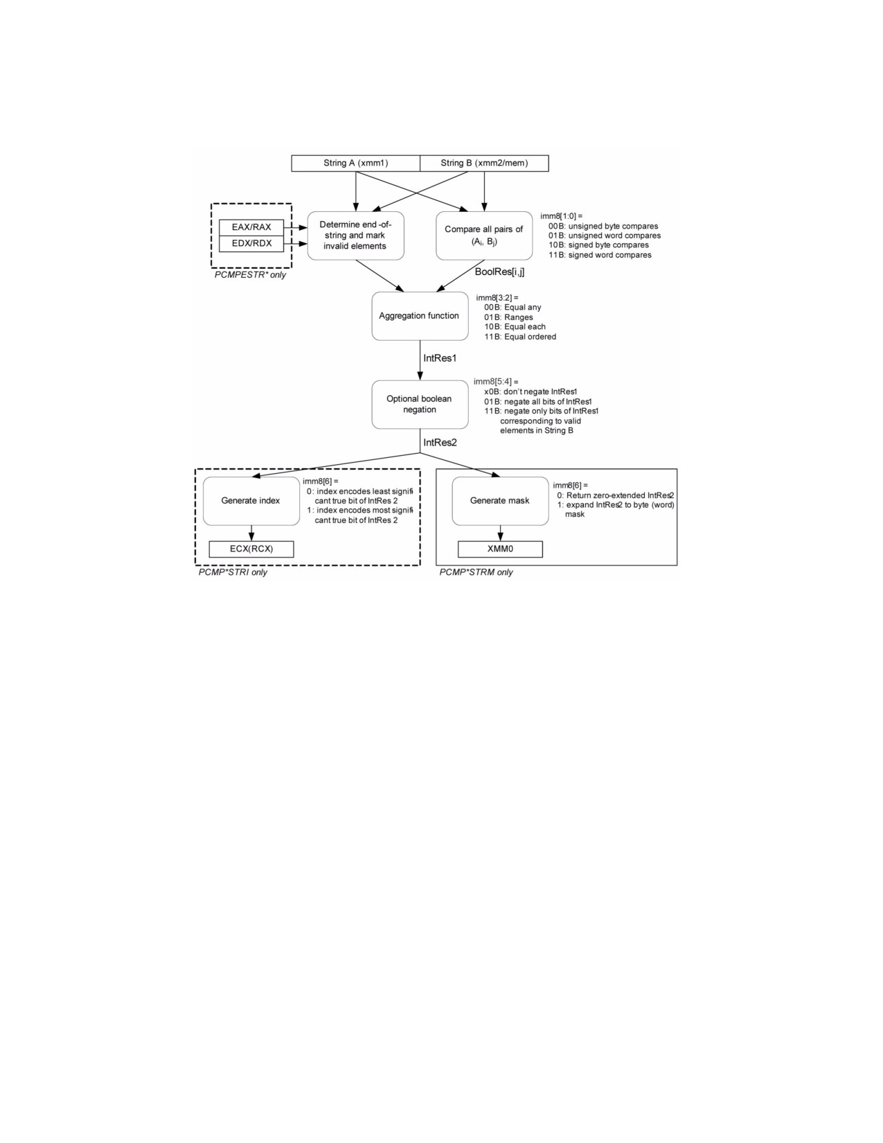
4.1.8
Diagram Comparison and Aggregation Process
Figure 4-1. Operation of PCMPSTRx and PCMPESTRx
4.2
COMMON TRANSFORMATION AND PRIMITIVE FUNCTIONS FOR SHA1XXX
AND SHA256XXX
The following primitive functions and transformations are used in the algorithmic descriptions of SHA1 and SHA256
instruction extensions SHA1NEXTE, SHA1RNDS4, SHA1MSG1, SHA1MSG2, SHA256RNDS4, SHA256MSG1, and
SHA256MSG2. The operands of these primitives and transformation are generally 32-bit DWORD integers.
• f0(): A bit oriented logical operation that derives a new dword from three SHA1 state variables (dword). This
function is used in SHA1 round 1 to 20 processing.
f0(B,C,D) := (B AND C) XOR ((NOT(B) AND D)
• f1(): A bit oriented logical operation that derives a new dword from three SHA1 state variables (dword). This
function is used in SHA1 round 21 to 40 processing.
f1(B,C,D) := B XOR C XOR D
• f2(): A bit oriented logical operation that derives a new dword from three SHA1 state variables (dword). This
function is used in SHA1 round 41 to 60 processing.
f2(B,C,D) := (B AND C) XOR (B AND D) XOR (C AND D)
• f3(): A bit oriented logical operation that derives a new dword from three SHA1 state variables (dword). This
function is used in SHA1 round 61 to 80 processing. It is the same as f1().
f3(B,C,D) := B XOR C XOR D
• Ch(): A bit oriented logical operation that derives a new dword from three SHA256 state variables (dword).
4-6
Vol. 2B
INSTRUCTION SET REFERENCE, M-U
Ch(E,F,G) := (E AND F) XOR ((NOT E) AND G)
• Maj(): A bit oriented logical operation that derives a new dword from three SHA256 state variables (dword).
Maj(A,B,C) := (A AND B) XOR (A AND C) XOR (B AND C)
ROR is rotate right operation
(A ROR N) := A[N-1:0] || A[Width-1:N]
ROL is rotate left operation
(A ROL N) := A ROR (Width-N)
SHR is the right shift operation
(A SHR N) := ZEROES[N-1:0] || A[Width-1:N]
• Σ0( ): A bit oriented logical and rotational transformation performed on a dword SHA256 state variable.
Σ0(A) := (A ROR 2) XOR (A ROR 13) XOR (A ROR 22)
• Σ1( ): A bit oriented logical and rotational transformation performed on a dword SHA256 state variable.
Σ1(E) := (E ROR 6) XOR (E ROR 11) XOR (E ROR 25)
• σ0( ): A bit oriented logical and rotational transformation performed on a SHA256 message dword used in the
message scheduling.
σ0(W) := (W ROR 7) XOR (W ROR 18) XOR (W SHR 3)
• σ1( ): A bit oriented logical and rotational transformation performed on a SHA256 message dword used in the
message scheduling.
σ1(W) := (W ROR 17) XOR (W ROR 19) XOR (W SHR 10)
• Ki: SHA1 Constants dependent on immediate i.
K0 = 0x5A827999
K1 = 0x6ED9EBA1
K2 = 0X8F1BBCDC
K3 = 0xCA62C1D6
4.3
INSTRUCTIONS (M-U)
Chapter 4 continues an alphabetical discussion of Intel® 64 and IA-32 instructions (M-U). See also: Chapter 3,
“Instruction Set Reference, A-L,” in the Intel® 64 and IA-32 Architectures Software Developer’s Manual, Volume
2A; Chapter 5, “Instruction Set Reference, V‚” in the Intel® 64 and IA-32 Architectures Software Developer’s
Manual, Volume 2C; and Chapter 6, “Instruction Set Reference, W-Z‚” in the Intel® 64 and IA-32 Architectures
Software Developer’s Manual, Volume 2D.
Vol. 2B
4-7

INSTRUCTION SET REFERENCE, M-U
MASKMOVDQU—Store Selected Bytes of Double Quadword
Opcode/
Op/
64/32-bit
CPUID
Description
Instruction
En
Mode
Feature
Flag
66 0F F7 /r
RM
V/V
SSE2
Selectively write bytes from xmm1 to
memory location using the byte mask in
MASKMOVDQU xmm1, xmm2
xmm2. The default memory location is
specified by DS:DI/EDI/RDI.
VEX.128.66.0F.WIG F7 /r
RM
V/V
AVX
Selectively write bytes from xmm1 to
memory location using the byte mask in
VMASKMOVDQU xmm1, xmm2
xmm2. The default memory location is
specified by DS:DI/EDI/RDI.
Instruction Operand Encoding1
Op/En
Operand 1
Operand 2
Operand 3
Operand 4
RM
ModRM:reg (r)
ModRM:r/m (r)
N/A
N/A
Description
Stores selected bytes from the source operand (first operand) into an 128-bit memory location. The mask operand
(second operand) selects which bytes from the source operand are written to memory. The source and mask oper-
ands are XMM registers. The memory location specified by the effective address in the DI/EDI/RDI register (the
default segment register is DS, but this may be overridden with a segment-override prefix). The memory location
does not need to be aligned on a natural boundary. (The size of the store address depends on the address-size
attribute.)
The most significant bit in each byte of the mask operand determines whether the corresponding byte in the source
operand is written to the corresponding byte location in memory: 0 indicates no write and 1 indicates write.
The MASKMOVDQU instruction generates a non-temporal hint to the processor to minimize cache pollution. The
non-temporal hint is implemented by using a write combining (WC) memory type protocol (see “Caching of
Temporal vs. Non-Temporal Data” in Chapter 10, of the Intel® 64 and IA-32 Architectures Software Developer’s
Manual, Volume 1). Because the WC protocol uses a weakly-ordered memory consistency model, a fencing opera-
tion implemented with the SFENCE or MFENCE instruction should be used in conjunction with MASKMOVDQU
instructions if multiple processors might use different memory types to read/write the destination memory loca-
tions.
Behavior with a mask of all 0s is as follows:
• No data will be written to memory.
• Signaling of breakpoints (code or data) is not guaranteed; different processor implementations may signal or
not signal these breakpoints.
• Exceptions associated with addressing memory and page faults may still be signaled (implementation
dependent).
• If the destination memory region is mapped as UC or WP, enforcement of associated semantics for these
memory types is not guaranteed (that is, is reserved) and is implementation-specific.
The MASKMOVDQU instruction can be used to improve performance of algorithms that need to merge data on a
byte-by-byte basis. MASKMOVDQU should not cause a read for ownership; doing so generates unnecessary band-
width since data is to be written directly using the byte-mask without allocating old data prior to the store.
In 64-bit mode, use of the REX.R prefix permits this instruction to access additional registers (XMM8-XMM15).
Note: In VEX-encoded versions, VEX.vvvv is reserved and must be 1111b otherwise instructions will #UD.
If VMASKMOVDQU is encoded with VEX.L= 1, an attempt to execute the instruction encoded with VEX.L= 1 will
cause an #UD exception.
1.ModRM.MOD = 011B required
4-8
Vol. 2B
MASKMOVDQU—Store Selected Bytes of Double Quadword
INSTRUCTION SET REFERENCE, M-U
Operation
IF (MASK[7] = 1)
THEN DEST[DI/EDI] := SRC[7:0] ELSE (* Memory location unchanged *); FI;
IF (MASK[15] = 1)
THEN DEST[DI/EDI +1] := SRC[15:8] ELSE (* Memory location unchanged *); FI;
(* Repeat operation for 3rd through 14th bytes in source operand *)
IF (MASK[127] = 1)
THEN DEST[DI/EDI +15] := SRC[127:120] ELSE (* Memory location unchanged *); FI;
Intel C/C++ Compiler Intrinsic Equivalent
void _mm_maskmoveu_si128(__m128i d, __m128i n, char * p)
Other Exceptions
See Table 2-21, “Type 4 Class Exception Conditions”; additionally:
#UD
If VEX.L= 1
If VEX.vvvv ≠ 1111B.
MASKMOVDQU—Store Selected Bytes of Double Quadword
Vol. 2B
4-9

INSTRUCTION SET REFERENCE, M-U
MASKMOVQ—Store Selected Bytes of Quadword
Opcode/
Op/
64-Bit
Compat/
Description
Instruction
En
Mode
Leg Mode
NP 0F F7 /r
RM
Valid
Valid
Selectively write bytes from mm1 to memory
location using the byte mask in mm2. The
MASKMOVQ mm1, mm2
default memory location is specified by
DS:DI/EDI/RDI.
Instruction Operand Encoding
Op/En
Operand 1
Operand 2
Operand 3
Operand 4
RM
ModRM:reg (r)
ModRM:r/m (r)
N/A
N/A
Description
Stores selected bytes from the source operand (first operand) into a 64-bit memory location. The mask operand
(second operand) selects which bytes from the source operand are written to memory. The source and mask oper-
ands are MMX technology registers. The memory location specified by the effective address in the DI/EDI/RDI
register (the default segment register is DS, but this may be overridden with a segment-override prefix). The
memory location does not need to be aligned on a natural boundary. (The size of the store address depends on the
address-size attribute.)
The most significant bit in each byte of the mask operand determines whether the corresponding byte in the source
operand is written to the corresponding byte location in memory: 0 indicates no write and 1 indicates write.
The MASKMOVQ instruction generates a non-temporal hint to the processor to minimize cache pollution. The non-
temporal hint is implemented by using a write combining (WC) memory type protocol (see “Caching of Temporal
vs. Non-Temporal Data” in Chapter 10, of the Intel® 64 and IA-32 Architectures Software Developer’s Manual,
Volume 1). Because the WC protocol uses a weakly-ordered memory consistency model, a fencing operation imple-
mented with the SFENCE or MFENCE instruction should be used in conjunction with MASKMOVQ instructions if
multiple processors might use different memory types to read/write the destination memory locations.
This instruction causes a transition from x87 FPU to MMX technology state (that is, the x87 FPU top-of-stack pointer
is set to 0 and the x87 FPU tag word is set to all 0s [valid]).
The behavior of the MASKMOVQ instruction with a mask of all 0s is as follows:
• No data will be written to memory.
• Transition from x87 FPU to MMX technology state will occur.
• Exceptions associated with addressing memory and page faults may still be signaled (implementation
dependent).
• Signaling of breakpoints (code or data) is not guaranteed (implementation dependent).
• If the destination memory region is mapped as UC or WP, enforcement of associated semantics for these
memory types is not guaranteed (that is, is reserved) and is implementation-specific.
The MASKMOVQ instruction can be used to improve performance for algorithms that need to merge data on a byte-
by-byte basis. It should not cause a read for ownership; doing so generates unnecessary bandwidth since data is
to be written directly using the byte-mask without allocating old data prior to the store.
In 64-bit mode, the memory address is specified by DS:RDI.
4-10
Vol. 2B
MASKMOVQ—Store Selected Bytes of Quadword
INSTRUCTION SET REFERENCE, M-U
Operation
IF (MASK[7] = 1)
THEN DEST[DI/EDI] := SRC[7:0] ELSE (* Memory location unchanged *); FI;
IF (MASK[15] = 1)
THEN DEST[DI/EDI +1] := SRC[15:8] ELSE (* Memory location unchanged *); FI;
(* Repeat operation for 3rd through 6th bytes in source operand *)
IF (MASK[63] = 1)
THEN DEST[DI/EDI +15] := SRC[63:56] ELSE (* Memory location unchanged *); FI;
Intel C/C++ Compiler Intrinsic Equivalent
void _mm_maskmove_si64(__m64d, __m64n, char * p)
Other Exceptions
See Table 23-8, “Exception Conditions for Legacy SIMD/MMX Instructions without FP Exception” in the Intel® 64
and IA-32 Architectures Software Developer’s Manual, Volume 3A.
MASKMOVQ—Store Selected Bytes of Quadword
Vol. 2B
4-11

INSTRUCTION SET REFERENCE, M-U
MAXPD—Maximum of Packed Double Precision Floating-Point Values
Opcode/
Op /
64/32
CPUID
Description
Instruction
En
bit Mode
Feature
Support
Flag
66 0F 5F /r
A
V/V
SSE2
Return the maximum double precision floating-point
MAXPD xmm1, xmm2/m128
values between xmm1 and xmm2/m128.
VEX.128.66.0F.WIG 5F /r
B
V/V
AVX
Return the maximum double precision floating-point
VMAXPD xmm1, xmm2, xmm3/m128
values between xmm2 and xmm3/m128.
VEX.256.66.0F.WIG 5F /r
B
V/V
AVX
Return the maximum packed double precision floating-
VMAXPD ymm1, ymm2, ymm3/m256
point values between ymm2 and ymm3/m256.
EVEX.128.66.0F.W1 5F /r
C
V/V
AVX512VL
Return the maximum packed double precision floating-
VMAXPD xmm1 {k1}{z}, xmm2,
AVX512F
point values between xmm2 and
xmm3/m128/m64bcst
xmm3/m128/m64bcst and store result in xmm1
subject to writemask k1.
EVEX.256.66.0F.W1 5F /r
C
V/V
AVX512VL
Return the maximum packed double precision floating-
VMAXPD ymm1 {k1}{z}, ymm2,
AVX512F
point values between ymm2 and
ymm3/m256/m64bcst
ymm3/m256/m64bcst and store result in ymm1
subject to writemask k1.
EVEX.512.66.0F.W1 5F /r
C
V/V
AVX512F
Return the maximum packed double precision floating-
VMAXPD zmm1 {k1}{z}, zmm2,
point values between zmm2 and
zmm3/m512/m64bcst{sae}
zmm3/m512/m64bcst and store result in zmm1
subject to writemask k1.
Instruction Operand Encoding
Op/En
Tuple Type
Operand 1
Operand 2
Operand 3
Operand 4
A
N/A
ModRM:reg (r, w)
ModRM:r/m (r)
N/A
N/A
B
N/A
ModRM:reg (w)
VEX.vvvv (r)
ModRM:r/m (r)
N/A
C
Full
ModRM:reg (w)
EVEX.vvvv (r)
ModRM:r/m (r)
N/A
Description
Performs a SIMD compare of the packed double precision floating-point values in the first source operand and the
second source operand and returns the maximum value for each pair of values to the destination operand.
If the values being compared are both 0.0s (of either sign), the value in the second operand (source operand) is
returned. If a value in the second operand is an SNaN, then SNaN is forwarded unchanged to the destination (that
is, a QNaN version of the SNaN is not returned).
If only one value is a NaN (SNaN or QNaN) for this instruction, the second operand (source operand), either a NaN
or a valid floating-point value, is written to the result. If instead of this behavior, it is required that the NaN source
operand (from either the first or second operand) be returned, the action of MAXPD can be emulated using a
sequence of instructions, such as a comparison followed by AND, ANDN, and OR.
EVEX encoded versions: The first source operand (the second operand) is a ZMM/YMM/XMM register. The second
source operand can be a ZMM/YMM/XMM register, a 512/256/128-bit memory location or a 512/256/128-bit vector
broadcasted from a 64-bit memory location. The destination operand is a ZMM/YMM/XMM register conditionally
updated with writemask k1.
VEX.256 encoded version: The first source operand is a YMM register. The second source operand can be a YMM
register or a 256-bit memory location. The destination operand is a YMM register. The upper bits (MAXVL-1:256) of
the corresponding ZMM register destination are zeroed.
VEX.128 encoded version: The first source operand is a XMM register. The second source operand can be a XMM
register or a 128-bit memory location. The destination operand is a XMM register. The upper bits (MAXVL-1:128) of
the corresponding ZMM register destination are zeroed.
128-bit Legacy SSE version: The second source can be an XMM register or an 128-bit memory location. The desti-
nation is not distinct from the first source XMM register and the upper bits (MAXVL-1:128) of the corresponding
ZMM register destination are unmodified.
4-12
Vol. 2B
MAXPD—Maximum of Packed Double Precision Floating-Point Values
INSTRUCTION SET REFERENCE, M-U
Operation
MAX(SRC1, SRC2)
{
IF ((SRC1 = 0.0) and (SRC2 = 0.0)) THEN DEST := SRC2;
ELSE IF (SRC1 = NaN) THEN DEST := SRC2; FI;
ELSE IF (SRC2 = NaN) THEN DEST := SRC2; FI;
ELSE IF (SRC1 > SRC2) THEN DEST := SRC1;
ELSE DEST := SRC2;
FI;
}
VMAXPD (EVEX encoded versions)
(KL, VL) = (2, 128), (4, 256), (8, 512)
FOR j := 0 TO KL-1
i := j * 64
IF k1[j] OR *no writemask*
THEN
IF (EVEX.b = 1) AND (SRC2 *is memory*)
THEN
DEST[i+63:i] := MAX(SRC1[i+63:i], SRC2[63:0])
ELSE
DEST[i+63:i] := MAX(SRC1[i+63:i], SRC2[i+63:i])
FI;
ELSE
IF *merging-masking*
; merging-masking
THEN *DEST[i+63:i] remains unchanged*
ELSE DEST[i+63:i] := 0
; zeroing-masking
FI
FI;
ENDFOR
DEST[MAXVL-1:VL] := 0
VMAXPD (VEX.256 encoded version)
DEST[63:0] := MAX(SRC1[63:0], SRC2[63:0])
DEST[127:64] := MAX(SRC1[127:64], SRC2[127:64])
DEST[191:128] := MAX(SRC1[191:128], SRC2[191:128])
DEST[255:192] := MAX(SRC1[255:192], SRC2[255:192])
DEST[MAXVL-1:256] := 0
VMAXPD (VEX.128 encoded version)
DEST[63:0] := MAX(SRC1[63:0], SRC2[63:0])
DEST[127:64] := MAX(SRC1[127:64], SRC2[127:64])
DEST[MAXVL-1:128] := 0
MAXPD—Maximum of Packed Double Precision Floating-Point Values
Vol. 2B
4-13
INSTRUCTION SET REFERENCE, M-U
MAXPD (128-bit Legacy SSE version)
DEST[63:0] := MAX(DEST[63:0], SRC[63:0])
DEST[127:64] := MAX(DEST[127:64], SRC[127:64])
DEST[MAXVL-1:128] (Unmodified)
Intel C/C++ Compiler Intrinsic Equivalent
VMAXPD __m512d _mm512_max_pd( __m512d a, __m512d b);
VMAXPD __m512d _mm512_mask_max_pd(__m512d s, __mmask8 k, __m512d a, __m512d b,);
VMAXPD __m512d _mm512_maskz_max_pd( __mmask8 k, __m512d a, __m512d b);
VMAXPD __m512d _mm512_max_round_pd( __m512d a, __m512d b, int);
VMAXPD __m512d _mm512_mask_max_round_pd(__m512d s, __mmask8 k, __m512d a, __m512d b, int);
VMAXPD __m512d _mm512_maskz_max_round_pd( __mmask8 k, __m512d a, __m512d b, int);
VMAXPD __m256d _mm256_mask_max_pd(__m5256d s, __mmask8 k, __m256d a, __m256d b);
VMAXPD __m256d _mm256_maskz_max_pd( __mmask8 k, __m256d a, __m256d b);
VMAXPD __m128d _mm_mask_max_pd(__m128d s, __mmask8 k, __m128d a, __m128d b);
VMAXPD __m128d _mm_maskz_max_pd( __mmask8 k, __m128d a, __m128d b);
VMAXPD __m256d _mm256_max_pd (__m256d a, __m256d b);
(V)MAXPD __m128d _mm_max_pd (__m128d a, __m128d b);
SIMD Floating-Point Exceptions
Invalid (including QNaN Source Operand), Denormal
Other Exceptions
Non-EVEX-encoded instruction, see Table 2-19, “Type 2 Class Exception Conditions”.
EVEX-encoded instruction, see Table 2-46, “Type E2 Class Exception Conditions”.
4-14
Vol. 2B
MAXPD—Maximum of Packed Double Precision Floating-Point Values

INSTRUCTION SET REFERENCE, M-U
MAXPS—Maximum of Packed Single Precision Floating-Point Values
Opcode/
Op /
64/32
CPUID
Description
Instruction
En
bit Mode
Feature
Support
Flag
NP 0F 5F /r
A
V/V
SSE
Return the maximum single precision floating-point values
MAXPS xmm1, xmm2/m128
between xmm1 and xmm2/mem.
VEX.128.0F.WIG 5F /r
B
V/V
AVX
Return the maximum single precision floating-point values
VMAXPS xmm1, xmm2,
between xmm2 and xmm3/mem.
xmm3/m128
VEX.256.0F.WIG 5F /r
B
V/V
AVX
Return the maximum single precision floating-point values
VMAXPS ymm1, ymm2,
between ymm2 and ymm3/mem.
ymm3/m256
EVEX.128.0F.W0 5F /r
C
V/V
AVX512VL
Return the maximum packed single precision floating-point
VMAXPS xmm1 {k1}{z}, xmm2,
AVX512F
values between xmm2 and xmm3/m128/m32bcst and store
xmm3/m128/m32bcst
result in xmm1 subject to writemask k1.
EVEX.256.0F.W0 5F /r
C
V/V
AVX512VL
Return the maximum packed single precision floating-point
VMAXPS ymm1 {k1}{z}, ymm2,
AVX512F
values between ymm2 and ymm3/m256/m32bcst and store
ymm3/m256/m32bcst
result in ymm1 subject to writemask k1.
EVEX.512.0F.W0 5F /r
C
V/V
AVX512F
Return the maximum packed single precision floating-point
VMAXPS zmm1 {k1}{z}, zmm2,
values between zmm2 and zmm3/m512/m32bcst and store
zmm3/m512/m32bcst{sae}
result in zmm1 subject to writemask k1.
Instruction Operand Encoding
Op/En
Tuple Type
Operand 1
Operand 2
Operand 3
Operand 4
A
N/A
ModRM:reg (r, w)
ModRM:r/m (r)
N/A
N/A
B
N/A
ModRM:reg (w)
VEX.vvvv (r)
ModRM:r/m (r)
N/A
C
Full
ModRM:reg (w)
EVEX.vvvv (r)
ModRM:r/m (r)
N/A
Description
Performs a SIMD compare of the packed single precision floating-point values in the first source operand and the
second source operand and returns the maximum value for each pair of values to the destination operand.
If the values being compared are both 0.0s (of either sign), the value in the second operand (source operand) is
returned. If a value in the second operand is an SNaN, then SNaN is forwarded unchanged to the destination (that
is, a QNaN version of the SNaN is not returned).
If only one value is a NaN (SNaN or QNaN) for this instruction, the second operand (source operand), either a NaN
or a valid floating-point value, is written to the result. If instead of this behavior, it is required that the NaN source
operand (from either the first or second operand) be returned, the action of MAXPS can be emulated using a
sequence of instructions, such as, a comparison followed by AND, ANDN, and OR.
EVEX encoded versions: The first source operand (the second operand) is a ZMM/YMM/XMM register. The second
source operand can be a ZMM/YMM/XMM register, a 512/256/128-bit memory location or a 512/256/128-bit vector
broadcasted from a 32-bit memory location. The destination operand is a ZMM/YMM/XMM register conditionally
updated with writemask k1.
VEX.256 encoded version: The first source operand is a YMM register. The second source operand can be a YMM
register or a 256-bit memory location. The destination operand is a YMM register. The upper bits (MAXVL-1:256) of
the corresponding ZMM register destination are zeroed.
VEX.128 encoded version: The first source operand is a XMM register. The second source operand can be a XMM
register or a 128-bit memory location. The destination operand is a XMM register. The upper bits (MAXVL-1:128) of
the corresponding ZMM register destination are zeroed.
128-bit Legacy SSE version: The second source can be an XMM register or an 128-bit memory location. The desti-
nation is not distinct from the first source XMM register and the upper bits (MAXVL-1:128) of the corresponding
ZMM register destination are unmodified.
MAXPS—Maximum of Packed Single Precision Floating-Point Values
Vol. 2B
4-15
INSTRUCTION SET REFERENCE, M-U
Operation
MAX(SRC1, SRC2)
{
IF ((SRC1 = 0.0) and (SRC2 = 0.0)) THEN DEST := SRC2;
ELSE IF (SRC1 = NaN) THEN DEST := SRC2; FI;
ELSE IF (SRC2 = NaN) THEN DEST := SRC2; FI;
ELSE IF (SRC1 > SRC2) THEN DEST := SRC1;
ELSE DEST := SRC2;
FI;
}
VMAXPS (EVEX encoded versions)
(KL, VL) = (4, 128), (8, 256), (16, 512)
FOR j := 0 TO KL-1
i := j * 32
IF k1[j] OR *no writemask*
THEN
IF (EVEX.b = 1) AND (SRC2 *is memory*)
THEN
DEST[i+31:i] := MAX(SRC1[i+31:i], SRC2[31:0])
ELSE
DEST[i+31:i] := MAX(SRC1[i+31:i], SRC2[i+31:i])
FI;
ELSE
IF *merging-masking*
; merging-masking
THEN *DEST[i+31:i] remains unchanged*
ELSE DEST[i+31:i] := 0
; zeroing-masking
FI
FI;
ENDFOR
DEST[MAXVL-1:VL] := 0
VMAXPS (VEX.256 encoded version)
DEST[31:0] := MAX(SRC1[31:0], SRC2[31:0])
DEST[63:32] := MAX(SRC1[63:32], SRC2[63:32])
DEST[95:64] := MAX(SRC1[95:64], SRC2[95:64])
DEST[127:96] := MAX(SRC1[127:96], SRC2[127:96])
DEST[159:128] := MAX(SRC1[159:128], SRC2[159:128])
DEST[191:160] := MAX(SRC1[191:160], SRC2[191:160])
DEST[223:192] := MAX(SRC1[223:192], SRC2[223:192])
DEST[255:224] := MAX(SRC1[255:224], SRC2[255:224])
DEST[MAXVL-1:256] := 0
VMAXPS (VEX.128 encoded version)
DEST[31:0] := MAX(SRC1[31:0], SRC2[31:0])
DEST[63:32] := MAX(SRC1[63:32], SRC2[63:32])
DEST[95:64] := MAX(SRC1[95:64], SRC2[95:64])
DEST[127:96] := MAX(SRC1[127:96], SRC2[127:96])
DEST[MAXVL-1:128] := 0
4-16
Vol. 2B
MAXPS—Maximum of Packed Single Precision Floating-Point Values