Intel 64 and IA-32 Architectures. Software Developer’s Manual (Collection, 2023) - page 74
INSTRUCTION SET REFERENCE, A-L
HSUBPD—Packed Double Precision Floating-Point Horizontal Subtract
Opcode/
Op/
64/32-bit
CPUID
Description
Instruction
En
Mode
Feature
Flag
66 0F 7D /r
RM
V/V
SSE3
Horizontal subtract packed double precision
floating-point values from xmm2/m128 to
HSUBPD xmm1, xmm2/m128
xmm1.
VEX.128.66.0F.WIG 7D /r
RVM
V/V
AVX
Horizontal subtract packed double precision
VHSUBPD xmm1,xmm2, xmm3/m128
floating-point values from xmm2 and
xmm3/mem.
VEX.256.66.0F.WIG 7D /r
RVM
V/V
AVX
Horizontal subtract packed double precision
VHSUBPD ymm1, ymm2, ymm3/m256
floating-point values from ymm2 and
ymm3/mem.
Instruction Operand Encoding
Op/En
Operand 1
Operand 2
Operand 3
Operand 4
RM
ModRM:reg (r, w)
ModRM:r/m (r)
N/A
N/A
RVM
ModRM:reg (w)
VEX.vvvv (r)
ModRM:r/m (r)
N/A
Description
The HSUBPD instruction subtracts horizontally the packed double precision floating-point numbers of both oper-
ands.
Subtracts the double precision floating-point value in the high quadword of the destination operand from the low
quadword of the destination operand and stores the result in the low quadword of the destination operand.
Subtracts the double precision floating-point value in the high quadword of the source operand from the low quad-
word of the source operand and stores the result in the high quadword of the destination operand.
In 64-bit mode, use of the REX.R prefix permits this instruction to access additional registers (XMM8-XMM15).
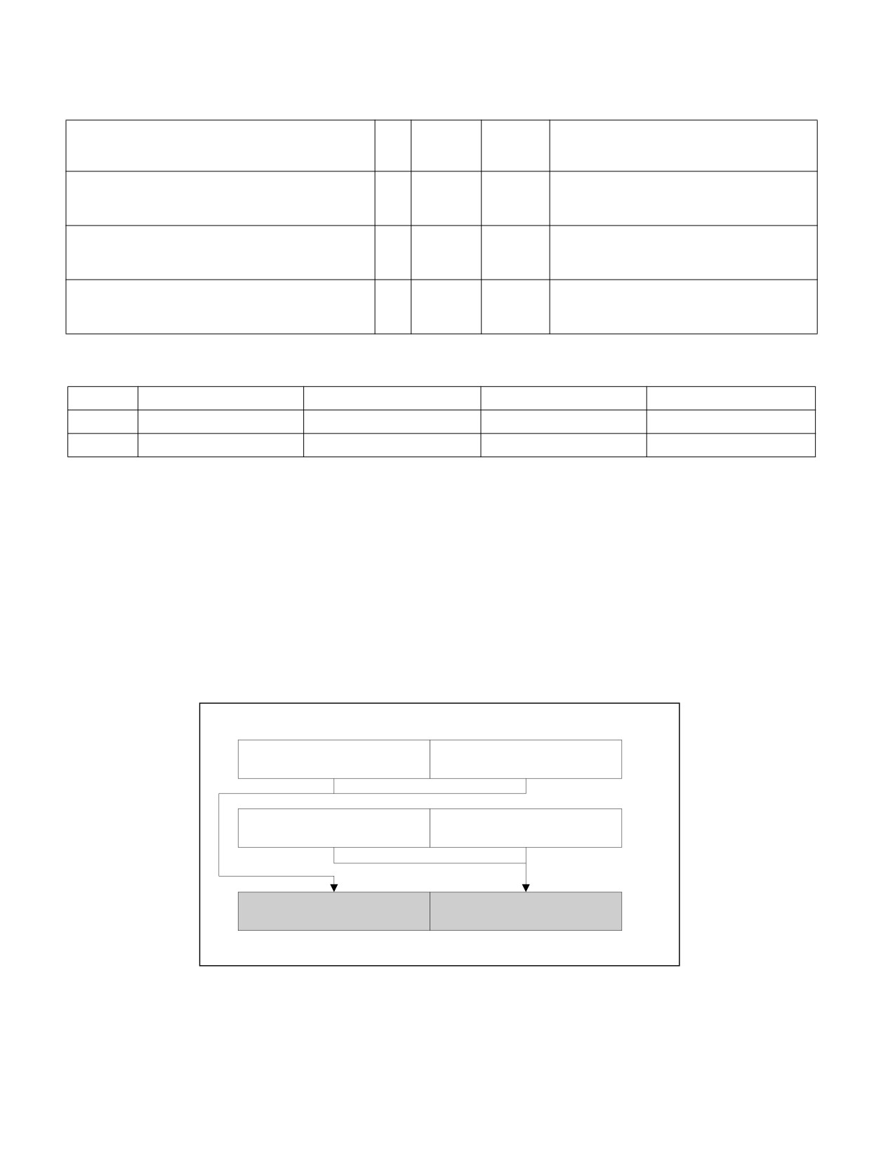
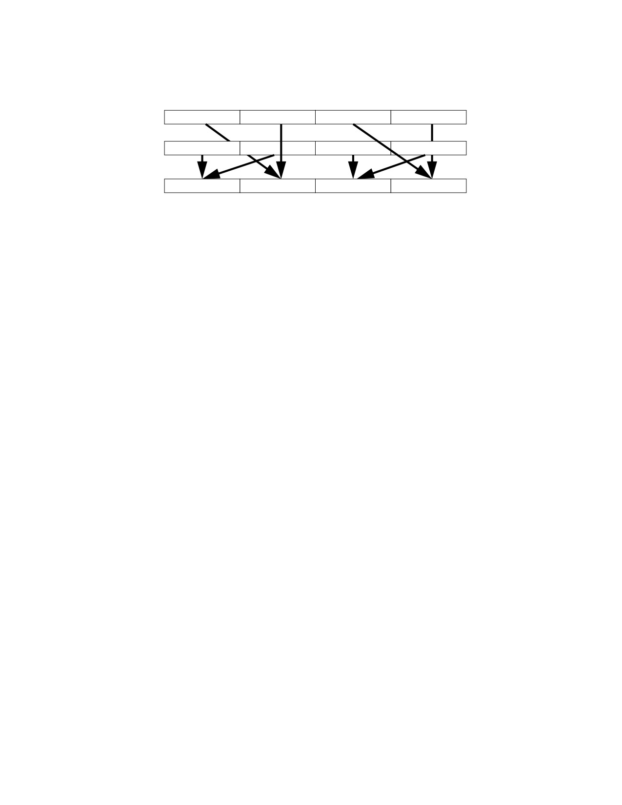
See Figure 3-21 for HSUBPD; see Figure 3-22 for VHSUBPD.
HSUBPD xmm1, xmm2/m128
xmm2
[127:64]
[63:0]
/m128
[127:64]
[63:0]
xmm1
xmm2/m128[63:0] -
Result:
xmm1[63:0] - xmm1[127:64]
xmm2/m128[127:64]
xmm1
[127:64]
[63:0]
OM15995
Figure 3-21. HSUBPD—Packed Double Precision Floating-Point Horizontal Subtract
HSUBPD—Packed Double Precision Floating-Point Horizontal Subtract
Vol. 2A
3-491
INSTRUCTION SET REFERENCE, A-L
SRC1
X3
X2
X1
X0
SRC2
Y3
Y2
Y1
Y0
DEST
Y2 - Y3
X2 - X3
Y0 - Y1
X0 - X1
Figure 3-22. VHSUBPD operation
128-bit Legacy SSE version: The second source can be an XMM register or an 128-bit memory location. The desti-
nation is not distinct from the first source XMM register and the upper bits (MAXVL-1:128) of the corresponding
YMM register destination are unmodified.
VEX.128 encoded version: the first source operand is an XMM register or 128-bit memory location. The destination
operand is an XMM register. The upper bits (MAXVL-1:128) of the corresponding YMM register destination are
zeroed.
VEX.256 encoded version: The first source operand is a YMM register. The second source operand can be a YMM
register or a 256-bit memory location. The destination operand is a YMM register.
Operation
HSUBPD (128-bit Legacy SSE version)
DEST[63:0] := SRC1[63:0] - SRC1[127:64]
DEST[127:64] := SRC2[63:0] - SRC2[127:64]
DEST[MAXVL-1:128] (Unmodified)
VHSUBPD (VEX.128 encoded version)
DEST[63:0] := SRC1[63:0] - SRC1[127:64]
DEST[127:64] := SRC2[63:0] - SRC2[127:64]
DEST[MAXVL-1:128] := 0
VHSUBPD (VEX.256 encoded version)
DEST[63:0] := SRC1[63:0] - SRC1[127:64]
DEST[127:64] := SRC2[63:0] - SRC2[127:64]
DEST[191:128] := SRC1[191:128] - SRC1[255:192]
DEST[255:192] := SRC2[191:128] - SRC2[255:192]
Intel C/C++ Compiler Intrinsic Equivalent
HSUBPD:
__m128d _mm_hsub_pd(__m128d a, __m128d b)
VHSUBPD:
__m256d _mm256_hsub_pd (__m256d a, __m256d b);
Exceptions
When the source operand is a memory operand, the operand must be aligned on a 16-byte boundary or a general-
protection exception (#GP) will be generated.
Numeric Exceptions
Overflow, Underflow, Invalid, Precision, Denormal
3-492
Vol. 2A
HSUBPD—Packed Double Precision Floating-Point Horizontal Subtract
INSTRUCTION SET REFERENCE, A-L
Other Exceptions
See Table 2-19, “Type 2 Class Exception Conditions”.
HSUBPD—Packed Double Precision Floating-Point Horizontal Subtract
Vol. 2A
3-493

INSTRUCTION SET REFERENCE, A-L
HSUBPS—Packed Single Precision Floating-Point Horizontal Subtract
Opcode/
Op/
64/32-bit
CPUID
Description
Instruction
En
Mode
Feature
Flag
F2 0F 7D /r
RM
V/V
SSE3
Horizontal subtract packed single precision
floating-point values from xmm2/m128 to
HSUBPS xmm1, xmm2/m128
xmm1.
VEX.128.F2.0F.WIG 7D /r
RVM
V/V
AVX
Horizontal subtract packed single precision
floating-point values from xmm2 and
VHSUBPS xmm1, xmm2, xmm3/m128
xmm3/mem.
VEX.256.F2.0F.WIG 7D /r
RVM
V/V
AVX
Horizontal subtract packed single precision
VHSUBPS ymm1, ymm2, ymm3/m256
floating-point values from ymm2 and
ymm3/mem.
Instruction Operand Encoding
Op/En
Operand 1
Operand 2
Operand 3
Operand 4
RM
ModRM:reg (r, w)
ModRM:r/m (r)
N/A
N/A
RVM
ModRM:reg (w)
VEX.vvvv (r)
ModRM:r/m (r)
N/A
Description
Subtracts the single precision floating-point value in the second dword of the destination operand from the first
dword of the destination operand and stores the result in the first dword of the destination operand.
Subtracts the single precision floating-point value in the fourth dword of the destination operand from the third
dword of the destination operand and stores the result in the second dword of the destination operand.
Subtracts the single precision floating-point value in the second dword of the source operand from the first dword
of the source operand and stores the result in the third dword of the destination operand.
Subtracts the single precision floating-point value in the fourth dword of the source operand from the third dword
of the source operand and stores the result in the fourth dword of the destination operand.
In 64-bit mode, use of the REX.R prefix permits this instruction to access additional registers (XMM8-XMM15).
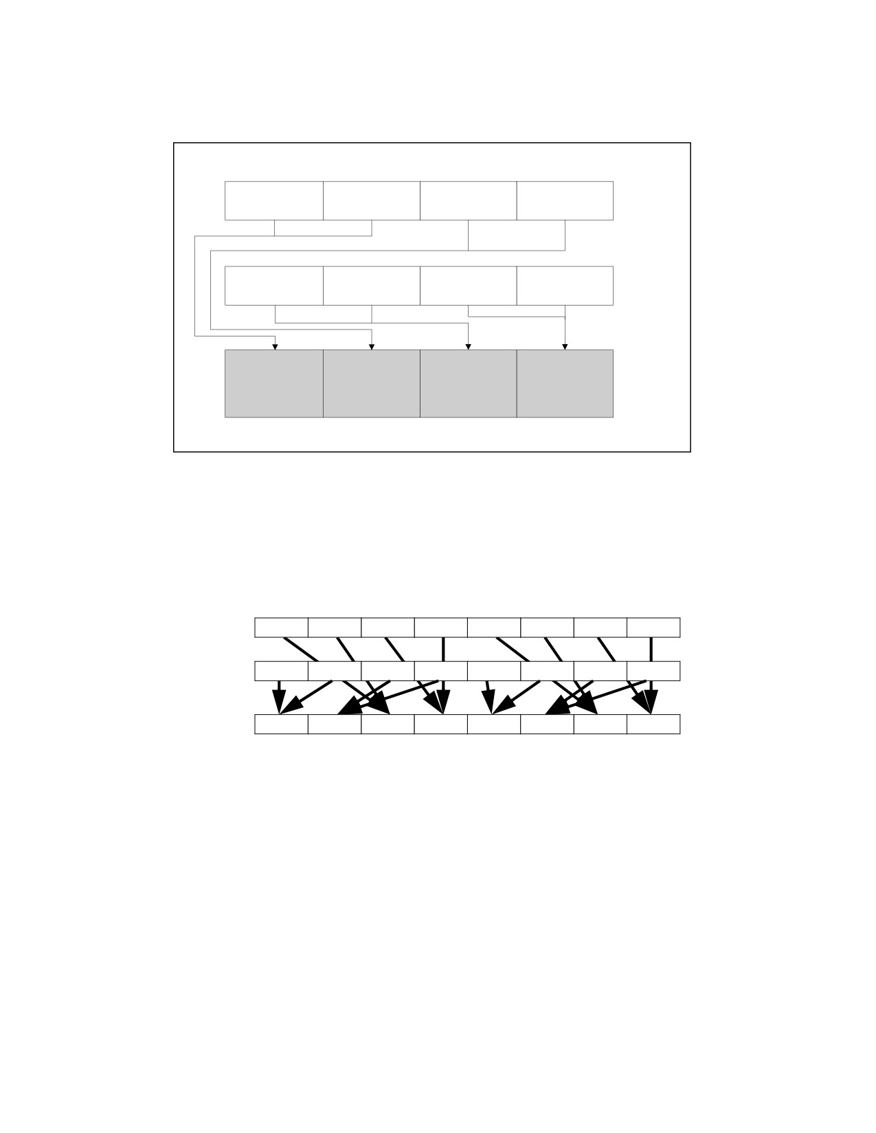
See Figure 3-23 for HSUBPS; see Figure 3-24 for VHSUBPS.
3-494
Vol. 2A
HSUBPS—Packed Single Precision Floating-Point Horizontal Subtract
INSTRUCTION SET REFERENCE, A-L
HSUBPS xmm1, xmm2/m128
xmm2/
[127:96]
[95:64]
[63:32]
[31:0]
m128
[127:96]
[95:64]
[63:32]
[31:0]
xmm1
xmm2/m128
xmm2/m128
xmm1[95:64] -
xmm1[31:0] -
RESULT:
[95:64] - xmm2/
[31:0] - xmm2/
xmm1[127:96]
xmm1[63:32]
xmm1
m128[127:96]
m128[63:32]
[127:96]
[95:64]
[63:32]
[31:0]
OM15996
Figure 3-23. HSUBPS—Packed Single Precision Floating-Point Horizontal Subtract
SRC1
X7
X6
X5
X4
X3
X2
X1
X0
SRC2
Y7
Y6
Y5
Y4
Y3
Y2
Y1
Y0
DEST
Y6-Y7
Y4-Y5
X6-X7
X4-X5
Y2-Y3
Y0-Y1
X2-X3
X0-X1
Figure 3-24. VHSUBPS Operation
128-bit Legacy SSE version: The second source can be an XMM register or an 128-bit memory location. The desti-
nation is not distinct from the first source XMM register and the upper bits (MAXVL-1:128) of the corresponding
YMM register destination are unmodified.
VEX.128 encoded version: the first source operand is an XMM register or 128-bit memory location. The destination
operand is an XMM register. The upper bits (MAXVL-1:128) of the corresponding YMM register destination are
zeroed.
VEX.256 encoded version: The first source operand is a YMM register. The second source operand can be a YMM
register or a 256-bit memory location. The destination operand is a YMM register.
HSUBPS—Packed Single Precision Floating-Point Horizontal Subtract
Vol. 2A
3-495
INSTRUCTION SET REFERENCE, A-L
Operation
HSUBPS (128-bit Legacy SSE version)
DEST[31:0] := SRC1[31:0] - SRC1[63:32]
DEST[63:32] := SRC1[95:64] - SRC1[127:96]
DEST[95:64] := SRC2[31:0] - SRC2[63:32]
DEST[127:96] := SRC2[95:64] - SRC2[127:96]
DEST[MAXVL-1:128] (Unmodified)
VHSUBPS (VEX.128 encoded version)
DEST[31:0] := SRC1[31:0] - SRC1[63:32]
DEST[63:32] := SRC1[95:64] - SRC1[127:96]
DEST[95:64] := SRC2[31:0] - SRC2[63:32]
DEST[127:96] := SRC2[95:64] - SRC2[127:96]
DEST[MAXVL-1:128] := 0
VHSUBPS (VEX.256 encoded version)
DEST[31:0] := SRC1[31:0] - SRC1[63:32]
DEST[63:32] := SRC1[95:64] - SRC1[127:96]
DEST[95:64] := SRC2[31:0] - SRC2[63:32]
DEST[127:96] := SRC2[95:64] - SRC2[127:96]
DEST[159:128] := SRC1[159:128] - SRC1[191:160]
DEST[191:160] := SRC1[223:192] - SRC1[255:224]
DEST[223:192] := SRC2[159:128] - SRC2[191:160]
DEST[255:224] := SRC2[223:192] - SRC2[255:224]
Intel C/C++ Compiler Intrinsic Equivalent
HSUBPS:
__m128 _mm_hsub_ps(__m128 a, __m128 b);
VHSUBPS:
__m256 _mm256_hsub_ps (__m256 a, __m256 b);
Exceptions
When the source operand is a memory operand, the operand must be aligned on a 16-byte boundary or a general-
protection exception (#GP) will be generated.
Numeric Exceptions
Overflow, Underflow, Invalid, Precision, Denormal
Other Exceptions
See Table 2-19, “Type 2 Class Exception Conditions”.
3-496
Vol. 2A
HSUBPS—Packed Single Precision Floating-Point Horizontal Subtract

INSTRUCTION SET REFERENCE, A-L
IDIV—Signed Divide
Opcode
Instruction
Op/
64-Bit
Compat/
Description
En
Mode
Leg Mode
F6 /7
IDIV r/m8
M
Valid
Valid
Signed divide AX by r/m8, with result stored in:
AL := Quotient, AH := Remainder.
REX + F6 /7
IDIV r/m81
M
Valid
N.E.
Signed divide AX by r/m8, with result stored in
AL := Quotient, AH := Remainder.
F7 /7
IDIV r/m16
M
Valid
Valid
Signed divide DX:AX by r/m16, with result
stored in AX := Quotient, DX := Remainder.
F7 /7
IDIV r/m32
M
Valid
Valid
Signed divide EDX:EAX by r/m32, with result
stored in EAX := Quotient, EDX := Remainder.
REX.W + F7 /7
IDIV r/m64
M
Valid
N.E.
Signed divide RDX:RAX by r/m64, with result
stored in RAX := Quotient, RDX := Remainder.
NOTES:
1. In 64-bit mode, r/m8 can not be encoded to access the following byte registers if a REX prefix is used: AH, BH, CH, DH.
Instruction Operand Encoding
Op/En
Operand 1
Operand 2
Operand 3
Operand 4
M
ModRM:r/m (r)
N/A
N/A
N/A
Description
Divides the (signed) value in the AX, DX:AX, or EDX:EAX (dividend) by the source operand (divisor) and stores the
result in the AX (AH:AL), DX:AX, or EDX:EAX registers. The source operand can be a general-purpose register or a
memory location. The action of this instruction depends on the operand size (dividend/divisor).
Non-integral results are truncated (chopped) towards 0. The remainder is always less than the divisor in magni-
tude. Overflow is indicated with the #DE (divide error) exception rather than with the CF flag.
In 64-bit mode, the instruction’s default operation size is 32 bits. Use of the REX.R prefix permits access to addi-
tional registers (R8-R15). Use of the REX.W prefix promotes operation to 64 bits. In 64-bit mode when REX.W is
applied, the instruction divides the signed value in RDX:RAX by the source operand. RAX contains a 64-bit
quotient; RDX contains a 64-bit remainder.
See the summary chart at the beginning of this section for encoding data and limits. See Table 3-51.
Table 3-51. IDIV Results
Operand Size
Dividend
Divisor
Quotient
Remainder
Quotient Range
Word/byte
AX
r/m8
AL
AH
−128 to +127
Doubleword/word
DX:AX
r/m16
AX
DX
−32,768 to +32,767
Quadword/doubleword
EDX:EAX
r/m32
EAX
EDX
−231 to 231 − 1
Doublequadword/ quadword
RDX:RAX
r/m64
RAX
RDX
−263 to 263 − 1
IDIV—Signed Divide
Vol. 2A
3-497
INSTRUCTION SET REFERENCE, A-L
Operation
IF SRC = 0
THEN #DE; (* Divide error *)
FI;
IF OperandSize = 8 (* Word/byte operation *)
THEN
temp := AX / SRC; (* Signed division *)
IF (temp > 7FH) or (temp < 80H)
(* If a positive result is greater than 7FH or a negative result is less than 80H *)
THEN #DE; (* Divide error *)
ELSE
AL := temp;
AH := AX SignedModulus SRC;
FI;
ELSE IF OperandSize = 16 (* Doubleword/word operation *)
THEN
temp := DX:AX / SRC; (* Signed division *)
IF (temp > 7FFFH) or (temp < 8000H)
(* If a positive result is greater than 7FFFH
or a negative result is less than 8000H *)
THEN
#DE; (* Divide error *)
ELSE
AX := temp;
DX := DX:AX SignedModulus SRC;
FI;
FI;
ELSE IF OperandSize = 32 (* Quadword/doubleword operation *)
temp := EDX:EAX / SRC; (* Signed division *)
IF (temp > 7FFFFFFFH) or (temp < 80000000H)
(* If a positive result is greater than 7FFFFFFFH
or a negative result is less than 80000000H *)
THEN
#DE; (* Divide error *)
ELSE
EAX := temp;
EDX := EDXE:AX SignedModulus SRC;
FI;
FI;
ELSE IF OperandSize = 64 (* Doublequadword/quadword operation *)
temp := RDX:RAX / SRC; (* Signed division *)
IF (temp > 7FFFFFFFFFFFFFFFH) or (temp < 8000000000000000H)
(* If a positive result is greater than 7FFFFFFFFFFFFFFFH
or a negative result is less than 8000000000000000H *)
THEN
#DE; (* Divide error *)
ELSE
RAX := temp;
RDX := RDE:RAX SignedModulus SRC;
FI;
FI;
FI;
3-498
Vol. 2A
IDIV—Signed Divide
INSTRUCTION SET REFERENCE, A-L
Flags Affected
The CF, OF, SF, ZF, AF, and PF flags are undefined.
Protected Mode Exceptions
#DE
If the source operand (divisor) is 0.
The signed result (quotient) is too large for the destination.
#GP(0)
If a memory operand effective address is outside the CS, DS, ES, FS, or GS segment limit.
If the DS, ES, FS, or GS register is used to access memory and it contains a NULL segment
selector.
#SS(0)
If a memory operand effective address is outside the SS segment limit.
#PF(fault-code)
If a page fault occurs.
#AC(0)
If alignment checking is enabled and an unaligned memory reference is made while the
current privilege level is 3.
#UD
If the LOCK prefix is used.
Real-Address Mode Exceptions
#DE
If the source operand (divisor) is 0.
The signed result (quotient) is too large for the destination.
#GP
If a memory operand effective address is outside the CS, DS, ES, FS, or GS segment limit.
#SS
If a memory operand effective address is outside the SS segment limit.
#UD
If the LOCK prefix is used.
Virtual-8086 Mode Exceptions
#DE
If the source operand (divisor) is 0.
The signed result (quotient) is too large for the destination.
#GP(0)
If a memory operand effective address is outside the CS, DS, ES, FS, or GS segment limit.
#SS(0)
If a memory operand effective address is outside the SS segment limit.
#PF(fault-code)
If a page fault occurs.
#AC(0)
If alignment checking is enabled and an unaligned memory reference is made.
#UD
If the LOCK prefix is used.
Compatibility Mode Exceptions
Same exceptions as in protected mode.
64-Bit Mode Exceptions
#SS(0)
If a memory address referencing the SS segment is in a non-canonical form.
#GP(0)
If the memory address is in a non-canonical form.
#DE
If the source operand (divisor) is 0
If the quotient is too large for the designated register.
#PF(fault-code)
If a page fault occurs.
#AC(0)
If alignment checking is enabled and an unaligned memory reference is made while the
current privilege level is 3.
#UD
If the LOCK prefix is used.
IDIV—Signed Divide
Vol. 2A
3-499

INSTRUCTION SET REFERENCE, A-L
IMUL—Signed Multiply
Opcode
Instruction
Op/
64-Bit
Compat/
Description
En
Mode
Leg Mode
F6 /5
IMUL r/m81
M
Valid
Valid
AX:= AL ∗ r/m byte.
F7 /5
IMUL r/m16
M
Valid
Valid
DX:AX := AX ∗ r/m word.
F7 /5
IMUL r/m32
M
Valid
Valid
EDX:EAX := EAX ∗ r/m32.
REX.W + F7 /5
IMUL r/m64
M
Valid
N.E.
RDX:RAX := RAX ∗ r/m64.
0F AF /r
IMUL r16, r/m16
RM
Valid
Valid
word register := word register ∗ r/m16.
0F AF /r
IMUL r32, r/m32
RM
Valid
Valid
doubleword register := doubleword register ∗
r/m32.
REX.W + 0F AF /r
IMUL r64, r/m64
RM
Valid
N.E.
Quadword register := Quadword register ∗
r/m64.
6B /r ib
IMUL r16, r/m16, imm8
RMI
Valid
Valid
word register := r/m16 ∗ sign-extended
immediate byte.
6B /r ib
IMUL r32, r/m32, imm8
RMI
Valid
Valid
doubleword register := r/m32 ∗ sign-
extended immediate byte.
REX.W + 6B /r ib
IMUL r64, r/m64, imm8
RMI
Valid
N.E.
Quadword register := r/m64 ∗ sign-extended
immediate byte.
69 /r iw
IMUL r16, r/m16, imm16
RMI
Valid
Valid
word register := r/m16 ∗ immediate word.
69 /r id
IMUL r32, r/m32, imm32
RMI
Valid
Valid
doubleword register := r/m32 ∗ immediate
doubleword.
REX.W + 69 /r id
IMUL r64, r/m64, imm32
RMI
Valid
N.E.
Quadword register := r/m64 ∗ immediate
doubleword.
NOTES:
1. In 64-bit mode, r/m8 can not be encoded to access the following byte registers if a REX prefix is used: AH, BH, CH, DH.
Instruction Operand Encoding
Op/En
Operand 1
Operand 2
Operand 3
Operand 4
M
ModRM:r/m (r, w)
N/A
N/A
N/A
RM
ModRM:reg (r, w)
ModRM:r/m (r)
N/A
N/A
RMI
ModRM:reg (r, w)
ModRM:r/m (r)
imm8/16/32
N/A
Description
Performs a signed multiplication of two operands. This instruction has three forms, depending on the number of
operands.
• One-operand form — This form is identical to that used by the MUL instruction. Here, the source operand (in
a general-purpose register or memory location) is multiplied by the value in the AL, AX, EAX, or RAX register
(depending on the operand size) and the product (twice the size of the input operand) is stored in the AX,
DX:AX, EDX:EAX, or RDX:RAX registers, respectively.
• Two-operand form — With this form the destination operand (the first operand) is multiplied by the source
operand (second operand). The destination operand is a general-purpose register and the source operand is an
immediate value, a general-purpose register, or a memory location. The intermediate product (twice the size of
the input operand) is truncated and stored in the destination operand location.
• Three-operand form — This form requires a destination operand (the first operand) and two source operands
(the second and the third operands). Here, the first source operand (which can be a general-purpose register
or a memory location) is multiplied by the second source operand (an immediate value). The intermediate
product (twice the size of the first source operand) is truncated and stored in the destination operand (a
general-purpose register).
3-500
Vol. 2A
IMUL—Signed Multiply
INSTRUCTION SET REFERENCE, A-L
When an immediate value is used as an operand, it is sign-extended to the length of the destination operand
format.
The CF and OF flags are set when the signed integer value of the intermediate product differs from the sign
extended operand-size-truncated product, otherwise the CF and OF flags are cleared.
The three forms of the IMUL instruction are similar in that the length of the product is calculated to twice the length
of the operands. With the one-operand form, the product is stored exactly in the destination. With the two- and
three- operand forms, however, the result is truncated to the length of the destination before it is stored in the
destination register. Because of this truncation, the CF or OF flag should be tested to ensure that no significant bits
are lost.
The two- and three-operand forms may also be used with unsigned operands because the lower half of the product
is the same regardless if the operands are signed or unsigned. The CF and OF flags, however, cannot be used to
determine if the upper half of the result is non-zero.
In 64-bit mode, the instruction’s default operation size is 32 bits. Use of the REX.R prefix permits access to addi-
tional registers (R8-R15). Use of the REX.W prefix promotes operation to 64 bits. Use of REX.W modifies the three
forms of the instruction as follows.
• One-operand form —The source operand (in a 64-bit general-purpose register or memory location) is
multiplied by the value in the RAX register and the product is stored in the RDX:RAX registers.
• Two-operand form — The source operand is promoted to 64 bits if it is a register or a memory location. The
destination operand is promoted to 64 bits.
• Three-operand form — The first source operand (either a register or a memory location) and destination
operand are promoted to 64 bits. If the source operand is an immediate, it is sign extended to 64 bits.
Operation
IF (NumberOfOperands = 1)
THEN IF (OperandSize = 8)
THEN
TMP_XP := AL ∗ SRC (* Signed multiplication; TMP_XP is a signed integer at twice the width of the SRC *);
AX := TMP_XP[15:0];
IF SignExtend(TMP_XP[7:0]) = TMP_XP
THEN CF := 0; OF := 0;
ELSE CF := 1; OF := 1; FI;
ELSE IF OperandSize = 16
THEN
TMP_XP := AX ∗ SRC (* Signed multiplication; TMP_XP is a signed integer at twice the width of the SRC *)
DX:AX := TMP_XP[31:0];
IF SignExtend(TMP_XP[15:0]) = TMP_XP
THEN CF := 0; OF := 0;
ELSE CF := 1; OF := 1; FI;
ELSE IF OperandSize = 32
THEN
TMP_XP := EAX ∗ SRC (* Signed multiplication; TMP_XP is a signed integer at twice the width of the SRC*)
EDX:EAX := TMP_XP[63:0];
IF SignExtend(TMP_XP[31:0]) = TMP_XP
THEN CF := 0; OF := 0;
ELSE CF := 1; OF := 1; FI;
ELSE (* OperandSize = 64 *)
TMP_XP := RAX ∗ SRC (* Signed multiplication; TMP_XP is a signed integer at twice the width of the SRC *)
EDX:EAX := TMP_XP[127:0];
IF SignExtend(TMP_XP[63:0]) = TMP_XP
THEN CF := 0; OF := 0;
ELSE CF := 1; OF := 1; FI;
FI;
IMUL—Signed Multiply
Vol. 2A
3-501
INSTRUCTION SET REFERENCE, A-L
FI;
ELSE IF (NumberOfOperands = 2)
THEN
TMP_XP := DEST ∗ SRC (* Signed multiplication; TMP_XP is a signed integer at twice the width of the SRC *)
DEST := TruncateToOperandSize(TMP_XP);
IF SignExtend(DEST) ≠ TMP_XP
THEN CF := 1; OF := 1;
ELSE CF := 0; OF := 0; FI;
ELSE (* NumberOfOperands = 3 *)
TMP_XP := SRC1 ∗ SRC2 (* Signed multiplication; TMP_XP is a signed integer at twice the width of the SRC1 *)
DEST := TruncateToOperandSize(TMP_XP);
IF SignExtend(DEST) ≠ TMP_XP
THEN CF := 1; OF := 1;
ELSE CF := 0; OF := 0; FI;
FI;
FI;
Flags Affected
For the one operand form of the instruction, the CF and OF flags are set when significant bits are carried into the
upper half of the result and cleared when the result fits exactly in the lower half of the result. For the two- and
three-operand forms of the instruction, the CF and OF flags are set when the result must be truncated to fit in the
destination operand size and cleared when the result fits exactly in the destination operand size. The SF, ZF, AF, and
PF flags are undefined.
Protected Mode Exceptions
#GP(0)
If a memory operand effective address is outside the CS, DS, ES, FS, or GS segment limit.
If the DS, ES, FS, or GS register is used to access memory and it contains a NULL NULL
segment selector.
#SS(0)
If a memory operand effective address is outside the SS segment limit.
#PF(fault-code)
If a page fault occurs.
#AC(0)
If alignment checking is enabled and an unaligned memory reference is made while the
current privilege level is 3.
#UD
If the LOCK prefix is used.
Real-Address Mode Exceptions
#GP
If a memory operand effective address is outside the CS, DS, ES, FS, or GS segment limit.
#SS
If a memory operand effective address is outside the SS segment limit.
#UD
If the LOCK prefix is used.
Virtual-8086 Mode Exceptions
#GP(0)
If a memory operand effective address is outside the CS, DS, ES, FS, or GS segment limit.
#SS(0)
If a memory operand effective address is outside the SS segment limit.
#PF(fault-code)
If a page fault occurs.
#AC(0)
If alignment checking is enabled and an unaligned memory reference is made.
#UD
If the LOCK prefix is used.
Compatibility Mode Exceptions
Same exceptions as in protected mode.
3-502
Vol. 2A
IMUL—Signed Multiply
INSTRUCTION SET REFERENCE, A-L
64-Bit Mode Exceptions
#SS(0)
If a memory address referencing the SS segment is in a non-canonical form.
#GP(0)
If the memory address is in a non-canonical form.
#PF(fault-code)
If a page fault occurs.
#AC(0)
If alignment checking is enabled and an unaligned memory reference is made while the
current privilege level is 3.
#UD
If the LOCK prefix is used.
IMUL—Signed Multiply
Vol. 2A
3-503

INSTRUCTION SET REFERENCE, A-L
IN—Input From Port
Opcode
Instruction
Op/
64-Bit
Compat/
Description
En
Mode
Leg Mode
E4 ib
IN AL, imm8
I
Valid
Valid
Input byte from imm8 I/O port address into
AL.
E5 ib
IN AX, imm8
I
Valid
Valid
Input word from imm8 I/O port address into
AX.
E5 ib
IN EAX, imm8
I
Valid
Valid
Input dword from imm8 I/O port address into
EAX.
EC
IN AL,DX
ZO
Valid
Valid
Input byte from I/O port in DX into AL.
ED
IN AX,DX
ZO
Valid
Valid
Input word from I/O port in DX into AX.
ED
IN EAX,DX
ZO
Valid
Valid
Input doubleword from I/O port in DX into
EAX.
Instruction Operand Encoding
Op/En
Operand 1
Operand 2
Operand 3
Operand 4
I
imm8
N/A
N/A
N/A
ZO
N/A
N/A
N/A
N/A
Description
Copies the value from the I/O port specified with the second operand (source operand) to the destination operand
(first operand). The source operand can be a byte-immediate or the DX register; the destination operand can be
register AL, AX, or EAX, depending on the size of the port being accessed (8, 16, or 32 bits, respectively). Using the
DX register as a source operand allows I/O port addresses from 0 to 65,535 to be accessed; using a byte immediate
allows I/O port addresses 0 to 255 to be accessed.
When accessing an 8-bit I/O port, the opcode determines the port size; when accessing a 16- and 32-bit I/O port,
the operand-size attribute determines the port size. At the machine code level, I/O instructions are shorter when
accessing 8-bit I/O ports. Here, the upper eight bits of the port address will be 0.
This instruction is only useful for accessing I/O ports located in the processor’s I/O address space. See Chapter 19,
“Input/Output,” in the Intel® 64 and IA-32 Architectures Software Developer’s Manual, Volume 1, for more infor-
mation on accessing I/O ports in the I/O address space.
This instruction’s operation is the same in non-64-bit modes and 64-bit mode.
Operation
IF ((PE = 1) and ((CPL > IOPL) or (VM = 1)))
THEN (* Protected mode with CPL > IOPL or virtual-8086 mode *)
IF (Any I/O Permission Bit for I/O port being accessed = 1)
THEN (* I/O operation is not allowed *)
#GP(0);
ELSE ( * I/O operation is allowed *)
DEST := SRC; (* Read from selected I/O port *)
FI;
ELSE (Real Mode or Protected Mode with CPL ≤ IOPL *)
DEST := SRC; (* Read from selected I/O port *)
FI;
Flags Affected
None
3-504
Vol. 2A
IN—Input From Port
INSTRUCTION SET REFERENCE, A-L
Protected Mode Exceptions
#GP(0)
If the CPL is greater than (has less privilege) the I/O privilege level (IOPL) and any of the
corresponding I/O permission bits in TSS for the I/O port being accessed is 1.
#PF(fault-code)
If a page fault occurs.
#UD
If the LOCK prefix is used.
Real-Address Mode Exceptions
#UD
If the LOCK prefix is used.
Virtual-8086 Mode Exceptions
#GP(0)
If any of the I/O permission bits in the TSS for the I/O port being accessed is 1.
#PF(fault-code)
If a page fault occurs.
#UD
If the LOCK prefix is used.
Compatibility Mode Exceptions
Same exceptions as in protected mode.
64-Bit Mode Exceptions
#GP(0)
If the CPL is greater than (has less privilege) the I/O privilege level (IOPL) and any of the
corresponding I/O permission bits in TSS for the I/O port being accessed is 1.
#PF(fault-code)
If a page fault occurs.
#UD
If the LOCK prefix is used.
IN—Input From Port
Vol. 2A
3-505

INSTRUCTION SET REFERENCE, A-L
INC—Increment by 1
Opcode
Instruction
Op/
64-Bit
Compat/
Description
En
Mode
Leg Mode
FE /0
INC r/m8
M
Valid
Valid
Increment r/m byte by 1.
REX + FE /0
INC r/m81
M
Valid
N.E.
Increment r/m byte by 1.
FF /0
INC r/m16
M
Valid
Valid
Increment r/m word by 1.
FF /0
INC r/m32
M
Valid
Valid
Increment r/m doubleword by 1.
REX.W + FF /0
INC r/m64
M
Valid
N.E.
Increment r/m quadword by 1.
40+ rw2
INC r16
O
N.E.
Valid
Increment word register by 1.
40+ rd
INC r32
O
N.E.
Valid
Increment doubleword register by 1.
NOTES:
1. In 64-bit mode, r/m8 can not be encoded to access the following byte registers if a REX prefix is used: AH, BH, CH, DH.
2. 40H through 47H are REX prefixes in 64-bit mode.
Instruction Operand Encoding
Op/En
Operand 1
Operand 2
Operand 3
Operand 4
M
ModRM:r/m (r, w)
N/A
N/A
N/A
O
opcode + rd (r, w)
N/A
N/A
N/A
Description
Adds 1 to the destination operand, while preserving the state of the CF flag. The destination operand can be a
register or a memory location. This instruction allows a loop counter to be updated without disturbing the CF flag.
(Use a ADD instruction with an immediate operand of 1 to perform an increment operation that does updates the
CF flag.)
This instruction can be used with a LOCK prefix to allow the instruction to be executed atomically.
In 64-bit mode, INC r16 and INC r32 are not encodable (because opcodes 40H through 47H are REX prefixes).
Otherwise, the instruction’s 64-bit mode default operation size is 32 bits. Use of the REX.R prefix permits access to
additional registers (R8-R15). Use of the REX.W prefix promotes operation to 64 bits.
Operation
DEST := DEST + 1;
Flags Affected
The CF flag is not affected. The OF, SF, ZF, AF, and PF flags are set according to the result.
Protected Mode Exceptions
#GP(0)
If the destination operand is located in a non-writable segment.
If a memory operand effective address is outside the CS, DS, ES, FS, or GS segment limit.
If the DS, ES, FS, or GS register is used to access memory and it contains a NULLsegment
selector.
#SS(0)
If a memory operand effective address is outside the SS segment limit.
#PF(fault-code)
If a page fault occurs.
#AC(0)
If alignment checking is enabled and an unaligned memory reference is made while the
current privilege level is 3.
#UD
If the LOCK prefix is used but the destination is not a memory operand.
3-506
Vol. 2A
INC—Increment by 1
INSTRUCTION SET REFERENCE, A-L
Real-Address Mode Exceptions
#GP
If a memory operand effective address is outside the CS, DS, ES, FS, or GS segment limit.
#SS
If a memory operand effective address is outside the SS segment limit.
#UD
If the LOCK prefix is used but the destination is not a memory operand.
Virtual-8086 Mode Exceptions
#GP(0)
If a memory operand effective address is outside the CS, DS, ES, FS, or GS segment limit.
#SS(0)
If a memory operand effective address is outside the SS segment limit.
#PF(fault-code)
If a page fault occurs.
#AC(0)
If alignment checking is enabled and an unaligned memory reference is made.
#UD
If the LOCK prefix is used but the destination is not a memory operand.
Compatibility Mode Exceptions
Same exceptions as in protected mode.
64-Bit Mode Exceptions
#SS(0)
If a memory address referencing the SS segment is in a non-canonical form.
#GP(0)
If the memory address is in a non-canonical form.
#PF(fault-code)
If a page fault occurs.
#AC(0)
If alignment checking is enabled and an unaligned memory reference is made while the
current privilege level is 3.
#UD
If the LOCK prefix is used but the destination is not a memory operand.
INC—Increment by 1
Vol. 2A
3-507

INSTRUCTION SET REFERENCE, A-L
INCSSPD/INCSSPQ—Increment Shadow Stack Pointer
Opcode/
Op /
64/32
CPUID
Description
Instruction
En
bit Mode
Feature
Support
Flag
F3 0F AE /05
R
V/V
CET_SS
Increment SSP by 4 * r32[7:0].
INCSSPD r32
F3 REX.W 0F AE /05
R
V/N.E.
CET_SS
Increment SSP by 8 * r64[7:0].
INCSSPQ r64
Instruction Operand Encoding
Op/En
Tuple Type
Operand 1
Operand 2
Operand 3
Operand 4
R
N/A
ModRM:r/m (r)
N/A
N/A
N/A
Description
This instruction can be used to increment the current shadow stack pointer by the operand size of the instruction
times the unsigned 8-bit value specified by bits 7:0 in the source operand. The instruction performs a pop and
discard of the first and last element on the shadow stack in the range specified by the unsigned 8-bit value in bits
7:0 of the source operand.
Operation
IF CPL = 3
IF (CR4.CET & IA32_U_CET.SH_STK_EN) = 0
THEN #UD; FI;
ELSE
IF (CR4.CET & IA32_S_CET.SH_STK_EN) = 0
THEN #UD; FI;
FI;
IF (operand size is 64-bit)
THEN
Range := R64[7:0];
shadow_stack_load 8 bytes from SSP;
IF Range > 0
THEN shadow_stack_load 8 bytes from SSP + 8 * (Range - 1);
FI;
SSP := SSP + Range * 8;
ELSE
Range := R32[7:0];
shadow_stack_load 4 bytes from SSP;
IF Range > 0
THEN shadow_stack_load 4 bytes from SSP + 4 * (Range - 1);
FI;
SSP := SSP + Range * 4;
FI;
Flags Affected
None.
Intel C/C++ Compiler Intrinsic Equivalent
INCSSPD
void _incsspd(int);
INCSSPQ
void _incsspq(int);
3-508
Vol. 2A
INCSSPD/INCSSPQ—Increment Shadow Stack Pointer
INSTRUCTION SET REFERENCE, A-L
Protected Mode Exceptions
#UD
If the LOCK prefix is used.
If CR4.CET = 0.
IF CPL = 3 and IA32_U_CET.SH_STK_EN = 0.
IF CPL < 3 and IA32_S_CET.SH_STK_EN = 0.
#PF(fault-code)
If a page fault occurs.
Real-Address Mode Exceptions
#UD
The INCSSP instruction is not recognized in real-address mode.
Virtual-8086 Mode Exceptions
#UD
The INCSSP instruction is not recognized in virtual-8086 mode.
Compatibility Mode Exceptions
Same exceptions as in protected mode.
64-Bit Mode Exceptions
Same exceptions as in protected mode.
INCSSPD/INCSSPQ—Increment Shadow Stack Pointer
Vol. 2A
3-509

INSTRUCTION SET REFERENCE, A-L
INS/INSB/INSW/INSD—Input from Port to String
Opcode
Instruction
Op/
64-Bit
Compat/
Description
En
Mode
Leg Mode
6C
INS m8, DX
ZO
Valid
Valid
Input byte from I/O port specified in DX into
memory location specified in ES:(E)DI or RDI.1
6D
INS m16, DX
ZO
Valid
Valid
Input word from I/O port specified in DX into
memory location specified in ES:(E)DI or RDI.1
6D
INS m32, DX
ZO
Valid
Valid
Input doubleword from I/O port specified in DX
into memory location specified in ES:(E)DI or
RDI.1
6C
INSB
ZO
Valid
Valid
Input byte from I/O port specified in DX into
memory location specified with ES:(E)DI or
RDI.1
6D
INSW
ZO
Valid
Valid
Input word from I/O port specified in DX into
memory location specified in ES:(E)DI or RDI.1
6D
INSD
ZO
Valid
Valid
Input doubleword from I/O port specified in DX
into memory location specified in ES:(E)DI or
RDI.1
NOTES:
1. In 64-bit mode, only 64-bit (RDI) and 32-bit (EDI) address sizes are supported. In non-64-bit mode, only 32-bit (EDI) and 16-bit (DI)
address sizes are supported.
Instruction Operand Encoding
Op/En
Operand 1
Operand 2
Operand 3
Operand 4
ZO
N/A
N/A
N/A
N/A
Description
Copies the data from the I/O port specified with the source operand (second operand) to the destination operand
(first operand). The source operand is an I/O port address (from 0 to 65,535) that is read from the DX register. The
destination operand is a memory location, the address of which is read from either the ES:DI, ES:EDI or the RDI
registers (depending on the address-size attribute of the instruction, 16, 32 or 64, respectively). (The ES segment
cannot be overridden with a segment override prefix.) The size of the I/O port being accessed (that is, the size of
the source and destination operands) is determined by the opcode for an 8-bit I/O port or by the operand-size attri-
bute of the instruction for a 16- or 32-bit I/O port.
At the assembly-code level, two forms of this instruction are allowed: the “explicit-operands” form and the “no-
operands” form. The explicit-operands form (specified with the INS mnemonic) allows the source and destination
operands to be specified explicitly. Here, the source operand must be “DX,” and the destination operand should be
a symbol that indicates the size of the I/O port and the destination address. This explicit-operands form is provided
to allow documentation; however, note that the documentation provided by this form can be misleading. That is,
the destination operand symbol must specify the correct type (size) of the operand (byte, word, or doubleword),
but it does not have to specify the correct location. The location is always specified by the ES:(E)DI registers,
which must be loaded correctly before the INS instruction is executed.
The no-operands form provides “short forms” of the byte, word, and doubleword versions of the INS instructions.
Here also DX is assumed by the processor to be the source operand and ES:(E)DI is assumed to be the destination
operand. The size of the I/O port is specified with the choice of mnemonic: INSB (byte), INSW (word), or INSD
(doubleword).
After the byte, word, or doubleword is transfer from the I/O port to the memory location, the DI/EDI/RDI register
is incremented or decremented automatically according to the setting of the DF flag in the EFLAGS register. (If the
DF flag is 0, the (E)DI register is incremented; if the DF flag is 1, the (E)DI register is decremented.) The (E)DI
register is incremented or decremented by 1 for byte operations, by 2 for word operations, or by 4 for doubleword
operations.
3-510
Vol. 2A
INS/INSB/INSW/INSD—Input from Port to String
INSTRUCTION SET REFERENCE, A-L
The INS, INSB, INSW, and INSD instructions can be preceded by the REP prefix for block input of ECX bytes, words,
or doublewords. See “REP/REPE/REPZ /REPNE/REPNZ—Repeat String Operation Prefix” in Chapter 4 of the Intel®
64 and IA-32 Architectures Software Developer’s Manual, Volume 2B, for a description of the REP prefix.
These instructions are only useful for accessing I/O ports located in the processor’s I/O address space. See Chapter
19, “Input/Output,” in the Intel® 64 and IA-32 Architectures Software Developer’s Manual, Volume 1, for more
information on accessing I/O ports in the I/O address space.
In 64-bit mode, default address size is 64 bits, 32 bit address size is supported using the prefix 67H. The address
of the memory destination is specified by RDI or EDI. 16-bit address size is not supported in 64-bit mode. The
operand size is not promoted.
These instructions may read from the I/O port without writing to the memory location if an exception or VM exit
occurs due to the write (e.g. #PF). If this would be problematic, for example because the I/O port read has side-
effects, software should ensure the write to the memory location does not cause an exception or VM exit.
Operation
IF ((PE = 1) and ((CPL > IOPL) or (VM = 1)))
THEN (* Protected mode with CPL > IOPL or virtual-8086 mode *)
IF (Any I/O Permission Bit for I/O port being accessed = 1)
THEN (* I/O operation is not allowed *)
#GP(0);
ELSE (* I/O operation is allowed *)
DEST := SRC; (* Read from I/O port *)
FI;
ELSE (Real Mode or Protected Mode with CPL IOPL *)
DEST := SRC; (* Read from I/O port *)
FI;
Non-64-bit Mode:
IF (Byte transfer)
THEN IF DF = 0
THEN (E)DI := (E)DI + 1;
ELSE (E)DI := (E)DI - 1; FI;
ELSE IF (Word transfer)
THEN IF DF = 0
THEN (E)DI := (E)DI + 2;
ELSE (E)DI := (E)DI - 2; FI;
ELSE (* Doubleword transfer *)
THEN IF DF = 0
THEN (E)DI := (E)DI + 4;
ELSE (E)DI := (E)DI - 4; FI;
FI;
FI;
FI64-bit Mode:
IF (Byte transfer)
THEN IF DF = 0
THEN (E|R)DI := (E|R)DI + 1;
ELSE (E|R)DI := (E|R)DI - 1; FI;
ELSE IF (Word transfer)
THEN IF DF = 0
THEN (E)DI := (E)DI + 2;
ELSE (E)DI := (E)DI - 2; FI;
ELSE (* Doubleword transfer *)
INS/INSB/INSW/INSD—Input from Port to String
Vol. 2A
3-511
INSTRUCTION SET REFERENCE, A-L
THEN IF DF = 0
THEN (E|R)DI := (E|R)DI + 4;
ELSE (E|R)DI := (E|R)DI - 4; FI;
FI;
FI;
Flags Affected
None
Protected Mode Exceptions
#GP(0)
If the CPL is greater than (has less privilege) the I/O privilege level (IOPL) and any of the
corresponding I/O permission bits in TSS for the I/O port being accessed is 1.
If the destination is located in a non-writable segment.
If an illegal memory operand effective address in the ES segments is given.
#PF(fault-code)
If a page fault occurs.
#AC(0)
If alignment checking is enabled and an unaligned memory reference is made while the
current privilege level is 3.
#UD
If the LOCK prefix is used.
Real-Address Mode Exceptions
#GP
If a memory operand effective address is outside the CS, DS, ES, FS, or GS segment limit.
#SS
If a memory operand effective address is outside the SS segment limit.
#UD
If the LOCK prefix is used.
Virtual-8086 Mode Exceptions
#GP(0)
If any of the I/O permission bits in the TSS for the I/O port being accessed is 1.
#PF(fault-code)
If a page fault occurs.
#AC(0)
If alignment checking is enabled and an unaligned memory reference is made.
#UD
If the LOCK prefix is used.
Compatibility Mode Exceptions
Same exceptions as in protected mode.
64-Bit Mode Exceptions
#SS(0)
If a memory address referencing the SS segment is in a non-canonical form.
#GP(0)
If the CPL is greater than (has less privilege) the I/O privilege level (IOPL) and any of the
corresponding I/O permission bits in TSS for the I/O port being accessed is 1.
If the memory address is in a non-canonical form.
#PF(fault-code)
If a page fault occurs.
#AC(0)
If alignment checking is enabled and an unaligned memory reference is made while the
current privilege level is 3.
#UD
If the LOCK prefix is used.
3-512
Vol. 2A
INS/INSB/INSW/INSD—Input from Port to String

INSTRUCTION SET REFERENCE, A-L
INSERTPS—Insert Scalar Single Precision Floating-Point Value
Opcode/
Op /
64/32
CPUID
Description
Instruction
En
bit Mode
Feature
Support
Flag
66 0F 3A 21 /r ib
A
V/V
SSE4_1
Insert a single precision floating-point value selected
INSERTPS xmm1, xmm2/m32, imm8
by imm8 from xmm2/m32 into xmm1 at the specified
destination element specified by imm8 and zero out
destination elements in xmm1 as indicated in imm8.
VEX.128.66.0F3A.WIG 21 /r ib
B
V/V
AVX
Insert a single precision floating-point value selected
VINSERTPS xmm1, xmm2,
by imm8 from xmm3/m32 and merge with values in
xmm3/m32, imm8
xmm2 at the specified destination element specified
by imm8 and write out the result and zero out
destination elements in xmm1 as indicated in imm8.
EVEX.128.66.0F3A.W0 21 /r ib
C
V/V
AVX512F
Insert a single precision floating-point value selected
VINSERTPS xmm1, xmm2,
by imm8 from xmm3/m32 and merge with values in
xmm3/m32, imm8
xmm2 at the specified destination element specified
by imm8 and write out the result and zero out
destination elements in xmm1 as indicated in imm8.
Instruction Operand Encoding
Op/En
Tuple Type
Operand 1
Operand 2
Operand 3
Operand 4
A
N/A
ModRM:reg (r, w)
ModRM:r/m (r)
imm8
N/A
B
N/A
ModRM:reg (w)
VEX.vvvv (r)
ModRM:r/m (r)
imm8
C
Tuple1 Scalar
ModRM:reg (w)
EVEX.vvvv (r)
ModRM:r/m (r)
imm8
Description
(register source form)
Copy a single precision scalar floating-point element into a 128-bit vector register. The immediate operand has
three fields, where the ZMask bits specify which elements of the destination will be set to zero, the Count_D bits
specify which element of the destination will be overwritten with the scalar value, and for vector register sources
the Count_S bits specify which element of the source will be copied. When the scalar source is a memory operand
the Count_S bits are ignored.
(memory source form)
Load a floating-point element from a 32-bit memory location and destination operand it into the first source at the
location indicated by the Count_D bits of the immediate operand. Store in the destination and zero out destination
elements based on the ZMask bits of the immediate operand.
128-bit Legacy SSE version: The first source register is an XMM register. The second source operand is either an
XMM register or a 32-bit memory location. The destination is not distinct from the first source XMM register and the
upper bits (MAXVL-1:128) of the corresponding register destination are unmodified.
VEX.128 and EVEX encoded version: The destination and first source register is an XMM register. The second
source operand is either an XMM register or a 32-bit memory location. The upper bits (MAXVL-1:128) of the corre-
sponding register destination are zeroed.
If VINSERTPS is encoded with VEX.L= 1, an attempt to execute the instruction encoded with VEX.L= 1 will cause
an #UD exception.
INSERTPS—Insert Scalar Single Precision Floating-Point Value
Vol. 2A
3-513
INSTRUCTION SET REFERENCE, A-L
Operation
VINSERTPS (VEX.128 and EVEX encoded version)
IF (SRC = REG) THEN COUNT_S := imm8[7:6]
ELSE COUNT_S := 0
COUNT_D := imm8[5:4]
ZMASK := imm8[3:0]
CASE (COUNT_S) OF
0: TMP := SRC2[31:0]
1: TMP := SRC2[63:32]
2: TMP := SRC2[95:64]
3: TMP := SRC2[127:96]
ESAC;
CASE (COUNT_D) OF
0: TMP2[31:0] := TMP
TMP2[127:32] := SRC1[127:32]
1: TMP2[63:32] := TMP
TMP2[31:0] := SRC1[31:0]
TMP2[127:64] := SRC1[127:64]
2: TMP2[95:64] := TMP
TMP2[63:0] := SRC1[63:0]
TMP2[127:96] := SRC1[127:96]
3: TMP2[127:96] := TMP
TMP2[95:0] := SRC1[95:0]
ESAC;
IF (ZMASK[0] = 1) THEN DEST[31:0] := 00000000H
ELSE DEST[31:0] := TMP2[31:0]
IF (ZMASK[1] = 1) THEN DEST[63:32] := 00000000H
ELSE DEST[63:32] := TMP2[63:32]
IF (ZMASK[2] = 1) THEN DEST[95:64] := 00000000H
ELSE DEST[95:64] := TMP2[95:64]
IF (ZMASK[3] = 1) THEN DEST[127:96] := 00000000H
ELSE DEST[127:96] := TMP2[127:96]
DEST[MAXVL-1:128] := 0
INSERTPS (128-bit Legacy SSE version)
IF (SRC = REG) THEN COUNT_S :=imm8[7:6]
ELSE COUNT_S :=0
COUNT_D := imm8[5:4]
ZMASK := imm8[3:0]
CASE (COUNT_S) OF
0: TMP := SRC[31:0]
1: TMP := SRC[63:32]
2: TMP := SRC[95:64]
3: TMP := SRC[127:96]
ESAC;
CASE (COUNT_D) OF
0: TMP2[31:0] := TMP
TMP2[127:32] := DEST[127:32]
1: TMP2[63:32] := TMP
TMP2[31:0] := DEST[31:0]
TMP2[127:64] := DEST[127:64]
2: TMP2[95:64] := TMP
3-514
Vol. 2A
INSERTPS—Insert Scalar Single Precision Floating-Point Value
INSTRUCTION SET REFERENCE, A-L
TMP2[63:0] := DEST[63:0]
TMP2[127:96] := DEST[127:96]
3: TMP2[127:96] := TMP
TMP2[95:0] := DEST[95:0]
ESAC;
IF (ZMASK[0] = 1) THEN DEST[31:0] := 00000000H
ELSE DEST[31:0] := TMP2[31:0]
IF (ZMASK[1] = 1) THEN DEST[63:32] := 00000000H
ELSE DEST[63:32] := TMP2[63:32]
IF (ZMASK[2] = 1) THEN DEST[95:64] := 00000000H
ELSE DEST[95:64] := TMP2[95:64]
IF (ZMASK[3] = 1) THEN DEST[127:96] := 00000000H
ELSE DEST[127:96] := TMP2[127:96]
DEST[MAXVL-1:128] (Unmodified)
Intel C/C++ Compiler Intrinsic Equivalent
VINSERTPS __m128 _mm_insert_ps(__m128 dst, __m128 src, const int nidx);
INSETRTPS __m128 _mm_insert_ps(__m128 dst, __m128 src, const int nidx);
SIMD Floating-Point Exceptions
None
Other Exceptions
Non-EVEX-encoded instruction, see Table 2-22, “Type 5 Class Exception Conditions”; additionally:
#UD
If VEX.L = 0.
EVEX-encoded instruction, see Table 2-57, “Type E9NF Class Exception Conditions”.
INSERTPS—Insert Scalar Single Precision Floating-Point Value
Vol. 2A
3-515

INSTRUCTION SET REFERENCE, A-L
INT n/INTO/INT3/INT1—Call to Interrupt Procedure
Opcode
Instruction
Op/
64-Bit
Compat/
Description
En
Mode
Leg Mode
CC
INT3
ZO
Valid
Valid
Generate breakpoint trap.
CD ib
INT imm8
I
Valid
Valid
Generate software interrupt with vector
specified by immediate byte.
CE
INTO
ZO
Invalid
Valid
Generate overflow trap if overflow flag is 1.
F1
INT1
ZO
Valid
Valid
Generate debug trap.
Instruction Operand Encoding
Op/En
Operand 1
Operand 2
Operand 3
Operand 4
ZO
N/A
N/A
N/A
N/A
I
imm8
N/A
N/A
N/A
Description
The INT n instruction generates a call to the interrupt or exception handler specified with the destination operand
(see the section titled “Interrupts and Exceptions” in Chapter 6 of the Intel® 64 and IA-32 Architectures Software
Developer’s Manual, Volume 1). The destination operand specifies a vector from 0 to 255, encoded as an 8-bit
unsigned intermediate value. Each vector provides an index to a gate descriptor in the IDT. The first 32 vectors are
reserved by Intel for system use. Some of these vectors are used for internally generated exceptions.
The INT n instruction is the general mnemonic for executing a software-generated call to an interrupt handler. The
INTO instruction is a special mnemonic for calling overflow exception (#OF), exception 4. The overflow interrupt
checks the OF flag in the EFLAGS register and calls the overflow interrupt handler if the OF flag is set to 1. (The
INTO instruction cannot be used in 64-bit mode.)
The INT3 instruction uses a one-byte opcode (CC) and is intended for calling the debug exception handler with a
breakpoint exception (#BP). (This one-byte form is useful because it can replace the first byte of any instruction at
which a breakpoint is desired, including other one-byte instructions, without overwriting other instructions.)
The INT1 instruction also uses a one-byte opcode (F1) and generates a debug exception (#DB) without setting any
bits in DR6.1 Hardware vendors may use the INT1 instruction for hardware debug. For that reason, Intel recom-
mends software vendors instead use the INT3 instruction for software breakpoints.
An interrupt generated by the INTO, INT3, or INT1 instruction differs from one generated by INT n in the following
ways:
• The normal IOPL checks do not occur in virtual-8086 mode. The interrupt is taken (without fault) with any IOPL
value.
• The interrupt redirection enabled by the virtual-8086 mode extensions (VME) does not occur. The interrupt is
always handled by a protected-mode handler.
(These features do not pertain to CD03, the “normal” 2-byte opcode for INT 3. Intel and Microsoft assemblers will
not generate the CD03 opcode from any mnemonic, but this opcode can be created by direct numeric code defini-
tion or by self-modifying code.)
The action of the INT n instruction (including the INTO, INT3, and INT1 instructions) is similar to that of a far call
made with the CALL instruction. The primary difference is that with the INT n instruction, the EFLAGS register is
pushed onto the stack before the return address. (The return address is a far address consisting of the current
values of the CS and EIP registers.) Returns from interrupt procedures are handled with the IRET instruction, which
pops the EFLAGS information and return address from the stack.
Each of the INT n, INTO, and INT3 instructions generates a general-protection exception (#GP) if the CPL is greater
than the DPL value in the selected gate descriptor in the IDT. In contrast, the INT1 instruction can deliver a #DB
1. The mnemonic ICEBP has also been used for the instruction with opcode F1.
3-516
Vol. 2A
INT n/INTO/INT3/INT1—Call to Interrupt Procedure

INSTRUCTION SET REFERENCE, A-L
even if the CPL is greater than the DPL of descriptor 1 in the IDT. (This behavior supports the use of INT1 by hard-
ware vendors performing hardware debug.)
The vector specifies an interrupt descriptor in the interrupt descriptor table (IDT); that is, it provides index into the
IDT. The selected interrupt descriptor in turn contains a pointer to an interrupt or exception handler procedure.
In protected mode, the IDT contains an array of 8-byte descriptors, each of which is an interrupt gate, trap gate,
or task gate. In real-address mode, the IDT is an array of 4-byte far pointers (2-byte code segment selector and
a 2-byte instruction pointer), each of which point directly to a procedure in the selected segment. (Note that in
real-address mode, the IDT is called the interrupt vector table, and its pointers are called interrupt vectors.)
The following decision table indicates which action in the lower portion of the table is taken given the conditions in
the upper portion of the table. Each Y in the lower section of the decision table represents a procedure defined in
the “Operation” section for this instruction (except #GP).
Table 3-52. Decision Table
PE
0
1
1
1
1
1
1
1
VM
-
-
-
-
-
0
1
1
IOPL
-
-
-
-
-
-
<3
=3
DPL/CPL
-
DPL<
-
DPL>
DPL=
DPL<
-
-
RELATIONSHIP
CPL
CPL
CPL or C
CPL & NC
INTERRUPT TYPE
-
S/W
-
-
-
-
-
-
GATE TYPE
-
-
Task
Trap or
Trap or
Trap or
Trap or
Trap or
Interrupt
Interrupt
Interrupt
Interrupt
Interrupt
REAL-ADDRESS-MODE
Y
PROTECTED-MODE
Y
Y
Y
Y
Y
Y
Y
TRAP-OR-INTERRUPT-
Y
Y
Y
Y
Y
GATE
INTER-PRIVILEGE-LEVEL-
Y
INTERRUPT
INTRA-PRIVILEGE-LEVEL-
Y
INTERRUPT
INTERRUPT-FROM-
Y
VIRTUAL-8086-MODE
TASK-GATE
Y
#GP
Y
Y
Y
NOTES:
− Don't Care.
Y Yes, action taken.
Blank Action not taken.
S/W Applies to INT n, INT3, and INTO, but not to INT1.
When the processor is executing in virtual-8086 mode, the IOPL determines the action of the INT n instruction. If
the IOPL is less than 3, the processor generates a #GP(selector) exception; if the IOPL is 3, the processor executes
a protected mode interrupt to privilege level 0. The interrupt gate's DPL must be set to 3 and the target CPL of the
interrupt handler procedure must be 0 to execute the protected mode interrupt to privilege level 0.
The interrupt descriptor table register (IDTR) specifies the base linear address and limit of the IDT. The initial base
address value of the IDTR after the processor is powered up or reset is 0.
Refer to Chapter 6, “Procedure Calls, Interrupts, and Exceptions” and Chapter 17, “Control-Flow Enforcement
Technology (CET)” in the Intel® 64 and IA-32 Architectures Software Developer’s Manual, Volume 1 for CET
details.
INT n/INTO/INT3/INT1—Call to Interrupt Procedure
Vol. 2A
3-517
INSTRUCTION SET REFERENCE, A-L
Instruction ordering. Instructions following an INT n may be fetched from memory before earlier instructions
complete execution, but they will not execute (even speculatively) until all instructions prior to the INT n have
completed execution (the later instructions may execute before data stored by the earlier instructions have become
globally visible). This applies also to the INTO, INT3, and INT1 instructions, but not to executions of INTO when
EFLAGS.OF = 0.
Operation
The following operational description applies not only to the INT n, INTO, INT3, or INT1 instructions, but also to
external interrupts, nonmaskable interrupts (NMIs), and exceptions. Some of these events push onto the stack an
error code.
The operational description specifies numerous checks whose failure may result in delivery of a nested exception.
In these cases, the original event is not delivered.
The operational description specifies the error code delivered by any nested exception. In some cases, the error
code is specified with a pseudofunction error_code(num,idt,ext), where idt and ext are bit values. The pseudofunc-
tion produces an error code as follows: (1) if idt is 0, the error code is (num & FCH) | ext; (2) if idt is 1, the error
code is (num « 3) | 2 | ext.
In many cases, the pseudofunction error_code is invoked with a pseudovariable EXT. The value of EXT depends on
the nature of the event whose delivery encountered a nested exception: if that event is a software interrupt (INT n,
INT3, or INTO), EXT is 0; otherwise (including INT1), EXT is 1.
IF PE = 0
THEN
GOTO REAL-ADDRESS-MODE;
ELSE (* PE = 1 *)
IF (EFLAGS.VM = 1 AND CR4.VME = 0 AND IOPL < 3 AND INT n)
THEN
#GP(0); (* Bit 0 of error code is 0 because INT n *)
ELSE
IF (EFLAGS.VM = 1 AND CR4.VME = 1 AND INT n)
THEN
Consult bit n of the software interrupt redirection bit map in the TSS;
IF bit n is clear
THEN (* redirect interrupt to 8086 program interrupt handler *)
Push EFLAGS[15:0];
(* if IOPL < 3, save VIF in IF position and save IOPL position as 3 *)
Push CS;
Push IP;
IF IOPL = 3
THEN IF := 0; (* Clear interrupt flag *)
ELSE VIF := 0; (* Clear virtual interrupt flag *)
FI;
TF := 0; (* Clear trap flag *)
load CS and EIP (lower 16 bits only) from entry n in interrupt vector table referenced from TSS;
ELSE
IF IOPL = 3
THEN GOTO PROTECTED-MODE;
ELSE #GP(0); (* Bit 0 of error code is 0 because INT n *)
FI;
FI;
ELSE (* Protected mode, IA-32e mode, or virtual-8086 mode interrupt *)
IF (IA32_EFER.LMA = 0)
THEN (* Protected mode, or virtual-8086 mode interrupt *)
GOTO PROTECTED-MODE;
ELSE (* IA-32e mode interrupt *)
GOTO IA-32e-MODE;
3-518
Vol. 2A
INT n/INTO/INT3/INT1—Call to Interrupt Procedure
INSTRUCTION SET REFERENCE, A-L
FI;
FI;
FI;
FI;
REAL-ADDRESS-MODE:
IF ((vector_number « 2) + 3) is not within IDT limit
THEN #GP; FI;
IF stack not large enough for a 6-byte return information
THEN #SS; FI;
Push (EFLAGS[15:0]);
IF := 0; (* Clear interrupt flag *)
TF := 0; (* Clear trap flag *)
AC := 0; (* Clear AC flag *)
Push(CS);
Push(IP);
(* No error codes are pushed in real-address mode*)
CS := IDT(Descriptor (vector_number « 2), selector));
EIP := IDT(Descriptor (vector_number « 2), offset)); (* 16 bit offset AND 0000FFFFH *)
END;
PROTECTED-MODE:
IF ((vector_number « 3) + 7) is not within IDT limits
or selected IDT descriptor is not an interrupt-, trap-, or task-gate type
THEN #GP(error_code(vector_number,1,EXT)); FI;
(* idt operand to error_code set because vector is used *)
IF software interrupt (* Generated by INT n, INT3, or INTO; does not apply to INT1 *)
THEN
IF gate DPL < CPL (* PE = 1, DPL < CPL, software interrupt *)
THEN #GP(error_code(vector_number,1,0)); FI;
(* idt operand to error_code set because vector is used *)
(* ext operand to error_code is 0 because INT n, INT3, or INTO*)
FI;
IF gate not present
THEN #NP(error_code(vector_number,1,EXT)); FI;
(* idt operand to error_code set because vector is used *)
IF task gate (* Specified in the selected interrupt table descriptor *)
THEN GOTO TASK-GATE;
ELSE GOTO TRAP-OR-INTERRUPT-GATE; (* PE = 1, trap/interrupt gate *)
FI;
END;
IA-32e-MODE:
IF INTO and CS.L = 1 (64-bit mode)
THEN #UD;
FI;
IF ((vector_number « 4) + 15) is not in IDT limits
or selected IDT descriptor is not an interrupt-, or trap-gate type
THEN #GP(error_code(vector_number,1,EXT));
(* idt operand to error_code set because vector is used *)
FI;
IF software interrupt (* Generated by INT n, INT3, or INTO; does not apply to INT1 *)
THEN
IF gate DPL < CPL (* PE = 1, DPL < CPL, software interrupt *)
THEN #GP(error_code(vector_number,1,0));
(* idt operand to error_code set because vector is used *)
(* ext operand to error_code is 0 because INT n, INT3, or INTO*)
INT n/INTO/INT3/INT1—Call to Interrupt Procedure
Vol. 2A
3-519
INSTRUCTION SET REFERENCE, A-L
FI;
FI;
IF gate not present
THEN #NP(error_code(vector_number,1,EXT));
(* idt operand to error_code set because vector is used *)
FI;
GOTO TRAP-OR-INTERRUPT-GATE; (* Trap/interrupt gate *)
END;
TASK-GATE: (* PE = 1, task gate *)
Read TSS selector in task gate (IDT descriptor);
IF local/global bit is set to local or index not within GDT limits
THEN #GP(error_code(TSS selector,0,EXT)); FI;
(* idt operand to error_code is 0 because selector is used *)
Access TSS descriptor in GDT;
IF TSS descriptor specifies that the TSS is busy (low-order 5 bits set to 00001)
THEN #GP(error_code(TSS selector,0,EXT)); FI;
(* idt operand to error_code is 0 because selector is used *)
IF TSS not present
THEN #NP(error_code(TSS selector,0,EXT)); FI;
(* idt operand to error_code is 0 because selector is used *)
SWITCH-TASKS (with nesting) to TSS;
IF interrupt caused by fault with error code
THEN
IF stack limit does not allow push of error code
THEN #SS(EXT); FI;
Push(error code);
FI;
IF EIP not within code segment limit
THEN #GP(EXT); FI;
END;
TRAP-OR-INTERRUPT-GATE:
Read new code-segment selector for trap or interrupt gate (IDT descriptor);
IF new code-segment selector is NULL
THEN #GP(EXT); FI; (* Error code contains NULL selector *)
IF new code-segment selector is not within its descriptor table limits
THEN #GP(error_code(new code-segment selector,0,EXT)); FI;
(* idt operand to error_code is 0 because selector is used *)
Read descriptor referenced by new code-segment selector;
IF descriptor does not indicate a code segment or new code-segment DPL > CPL
THEN #GP(error_code(new code-segment selector,0,EXT)); FI;
(* idt operand to error_code is 0 because selector is used *)
IF new code-segment descriptor is not present,
THEN #NP(error_code(new code-segment selector,0,EXT)); FI;
(* idt operand to error_code is 0 because selector is used *)
IF new code segment is non-conforming with DPL < CPL
THEN
IF VM = 0
THEN
GOTO INTER-PRIVILEGE-LEVEL-INTERRUPT;
(* PE = 1, VM = 0, interrupt or trap gate, nonconforming code segment,
DPL < CPL *)
ELSE (* VM = 1 *)
IF new code-segment DPL ≠ 0
THEN #GP(error_code(new code-segment selector,0,EXT));
3-520
Vol. 2A
INT n/INTO/INT3/INT1—Call to Interrupt Procedure
INSTRUCTION SET REFERENCE, A-L
(* idt operand to error_code is 0 because selector is used *)
GOTO INTERRUPT-FROM-VIRTUAL-8086-MODE; FI;
(* PE = 1, interrupt or trap gate, DPL < CPL, VM = 1 *)
FI;
ELSE (* PE = 1, interrupt or trap gate, DPL ≥ CPL *)
IF VM = 1
THEN #GP(error_code(new code-segment selector,0,EXT));
(* idt operand to error_code is 0 because selector is used *)
IF new code segment is conforming or new code-segment DPL = CPL
THEN
GOTO INTRA-PRIVILEGE-LEVEL-INTERRUPT;
ELSE (* PE = 1, interrupt or trap gate, nonconforming code segment, DPL > CPL *)
#GP(error_code(new code-segment selector,0,EXT));
(* idt operand to error_code is 0 because selector is used *)
FI;
FI;
END;
INTER-PRIVILEGE-LEVEL-INTERRUPT:
(* PE = 1, interrupt or trap gate, non-conforming code segment, DPL < CPL *)
IF (IA32_EFER.LMA = 0) (* Not IA-32e mode *)
THEN
(* Identify stack-segment selector for new privilege level in current TSS *)
IF current TSS is 32-bit
THEN
TSSstackAddress := (new code-segment DPL « 3) + 4;
IF (TSSstackAddress + 5) > current TSS limit
THEN #TS(error_code(current TSS selector,0,EXT)); FI;
(* idt operand to error_code is 0 because selector is used *)
NewSS := 2 bytes loaded from (TSS base + TSSstackAddress + 4);
NewESP := 4 bytes loaded from (TSS base + TSSstackAddress);
ELSE
(* current TSS is 16-bit *)
TSSstackAddress := (new code-segment DPL « 2) + 2
IF (TSSstackAddress + 3) > current TSS limit
THEN #TS(error_code(current TSS selector,0,EXT)); FI;
(* idt operand to error_code is 0 because selector is used *)
NewSS := 2 bytes loaded from (TSS base + TSSstackAddress + 2);
NewESP := 2 bytes loaded from (TSS base + TSSstackAddress);
FI;
IF NewSS is NULL
THEN #TS(EXT); FI;
IF NewSS index is not within its descriptor-table limits
or NewSS RPL ≠ new code-segment DPL
THEN #TS(error_code(NewSS,0,EXT)); FI;
(* idt operand to error_code is 0 because selector is used *)
Read new stack-segment descriptor for NewSS in GDT or LDT;
IF new stack-segment DPL ≠ new code-segment DPL
or new stack-segment Type does not indicate writable data segment
THEN #TS(error_code(NewSS,0,EXT)); FI;
(* idt operand to error_code is 0 because selector is used *)
IF NewSS is not present
THEN #SS(error_code(NewSS,0,EXT)); FI;
(* idt operand to error_code is 0 because selector is used *)
NewSSP := IA32_PLi_SSP (* where i = new code-segment DPL *)
ELSE (* IA-32e mode *)
INT n/INTO/INT3/INT1—Call to Interrupt Procedure
Vol. 2A
3-521
INSTRUCTION SET REFERENCE, A-L
IF IDT-gate IST = 0
THEN TSSstackAddress := (new code-segment DPL « 3) + 4;
ELSE TSSstackAddress := (IDT gate IST « 3) + 28;
FI;
IF (TSSstackAddress + 7) > current TSS limit
THEN #TS(error_code(current TSS selector,0,EXT); FI;
(* idt operand to error_code is 0 because selector is used *)
NewRSP := 8 bytes loaded from (current TSS base + TSSstackAddress);
NewSS := new code-segment DPL; (* NULL selector with RPL = new CPL *)
IF IDT-gate IST = 0
THEN
NewSSP := IA32_PLi_SSP (* where i = new code-segment DPL *)
ELSE
NewSSPAddress = IA32_INTERRUPT_SSP_TABLE_ADDR + (IDT-gate IST « 3)
(* Check if shadow stacks are enabled at CPL 0 *)
IF ShadowStackEnabled(CPL 0)
THEN NewSSP := 8 bytes loaded from NewSSPAddress; FI;
FI;
FI;
IF IDT gate is 32-bit
THEN
IF new stack does not have room for 24 bytes (error code pushed)
or 20 bytes (no error code pushed)
THEN #SS(error_code(NewSS,0,EXT)); FI;
(* idt operand to error_code is 0 because selector is used *)
FI
ELSE
IF IDT gate is 16-bit
THEN
IF new stack does not have room for 12 bytes (error code pushed)
or 10 bytes (no error code pushed);
THEN #SS(error_code(NewSS,0,EXT)); FI;
(* idt operand to error_code is 0 because selector is used *)
ELSE (* 64-bit IDT gate*)
IF StackAddress is non-canonical
THEN #SS(EXT); FI; (* Error code contains NULL selector *)
FI;
FI;
IF (IA32_EFER.LMA = 0) (* Not IA-32e mode *)
THEN
IF instruction pointer from IDT gate is not within new code-segment limits
THEN #GP(EXT); FI; (* Error code contains NULL selector *)
ESP := NewESP;
SS := NewSS; (* Segment descriptor information also loaded *)
ELSE (* IA-32e mode *)
IF instruction pointer from IDT gate contains a non-canonical address
THEN #GP(EXT); FI; (* Error code contains NULL selector *)
RSP := NewRSP & FFFFFFFFFFFFFFF0H;
SS := NewSS;
FI;
IF IDT gate is 32-bit
THEN
CS:EIP := Gate(CS:EIP); (* Segment descriptor information also loaded *)
ELSE
3-522
Vol. 2A
INT n/INTO/INT3/INT1—Call to Interrupt Procedure
INSTRUCTION SET REFERENCE, A-L
IF IDT gate 16-bit
THEN
CS:IP := Gate(CS:IP);
(* Segment descriptor information also loaded *)
ELSE (* 64-bit IDT gate *)
CS:RIP := Gate(CS:RIP);
(* Segment descriptor information also loaded *)
FI;
FI;
IF IDT gate is 32-bit
THEN
Push(far pointer to old stack);
(* Old SS and ESP, 3 words padded to 4 *)
Push(EFLAGS);
Push(far pointer to return instruction);
(* Old CS and EIP, 3 words padded to 4 *)
Push(ErrorCode); (* If needed, 4 bytes *)
ELSE
IF IDT gate 16-bit
THEN
Push(far pointer to old stack);
(* Old SS and SP, 2 words *)
Push(EFLAGS(15:0]);
Push(far pointer to return instruction);
(* Old CS and IP, 2 words *)
Push(ErrorCode); (* If needed, 2 bytes *)
ELSE (* 64-bit IDT gate *)
Push(far pointer to old stack);
(* Old SS and SP, each an 8-byte push *)
Push(RFLAGS); (* 8-byte push *)
Push(far pointer to return instruction);
(* Old CS and RIP, each an 8-byte push *)
Push(ErrorCode); (* If needed, 8-bytes *)
FI;
FI;
IF ShadowStackEnabled(CPL) AND CPL = 3
THEN
IF IA32_EFER.LMA = 0
THEN IA32_PL3_SSP := SSP;
ELSE (* adjust so bits 63:N get the value of bit N-1, where N is the CPU’s maximum linear-address width *)
IA32_PL3_SSP := LA_adjust(SSP);
FI;
FI;
CPL := new code-segment DPL;
CS(RPL) := CPL;
IF ShadowStackEnabled(CPL)
oldSSP := SSP
SSP := NewSSP
IF SSP & 0x07 != 0
THEN #GP(0); FI;
(* Token and CS:LIP:oldSSP pushed on shadow stack must be contained in a naturally aligned 32-byte region *)
IF (SSP & ~0x1F) != ((SSP - 24) & ~0x1F)
#GP(0); FI;
IF ((IA32_EFER.LMA and CS.L) = 0 AND SSP[63:32] != 0)
INT n/INTO/INT3/INT1—Call to Interrupt Procedure
Vol. 2A
3-523
INSTRUCTION SET REFERENCE, A-L
THEN #GP(0); FI;
expected_token_value = SSP
(* busy bit - bit position 0 - must be clear *)
new_token_value = SSP | BUSY_BIT
(* Set the busy bit *)
IF shadow_stack_lock_cmpxchg8b(SSP, new_token_value, expected_token_value) != expected_token_value
THEN #GP(0); FI;
IF oldSS.DPL != 3
ShadowStackPush8B(oldCS); (* Padded with 48 high-order bits of 0 *)
ShadowStackPush8B(oldCSBASE + oldRIP); (* Padded with 32 high-order bits of 0 for 32 bit LIP*)
ShadowStackPush8B(oldSSP);
FI;
FI;
IF EndbranchEnabled (CPL)
IA32_S_CET.TRACKER = WAIT_FOR_ENDBRANCH;
IA32_S_CET.SUPPRESS = 0
FI;
IF IDT gate is interrupt gate
THEN IF := 0 (* Interrupt flag set to 0, interrupts disabled *); FI;
TF := 0;
VM := 0;
RF := 0;
NT := 0;
END;
INTERRUPT-FROM-VIRTUAL-8086-MODE:
(* Identify stack-segment selector for privilege level 0 in current TSS *)
IF current TSS is 32-bit
THEN
IF TSS limit < 9
THEN #TS(error_code(current TSS selector,0,EXT)); FI;
(* idt operand to error_code is 0 because selector is used *)
NewSS := 2 bytes loaded from (current TSS base + 8);
NewESP := 4 bytes loaded from (current TSS base + 4);
ELSE (* current TSS is 16-bit *)
IF TSS limit < 5
THEN #TS(error_code(current TSS selector,0,EXT)); FI;
(* idt operand to error_code is 0 because selector is used *)
NewSS := 2 bytes loaded from (current TSS base + 4);
NewESP := 2 bytes loaded from (current TSS base + 2);
FI;
IF NewSS is NULL
THEN #TS(EXT); FI; (* Error code contains NULL selector *)
IF NewSS index is not within its descriptor table limits
or NewSS RPL ≠ 0
THEN #TS(error_code(NewSS,0,EXT)); FI;
(* idt operand to error_code is 0 because selector is used *)
Read new stack-segment descriptor for NewSS in GDT or LDT;
IF new stack-segment DPL ≠ 0 or stack segment does not indicate writable data segment
THEN #TS(error_code(NewSS,0,EXT)); FI;
(* idt operand to error_code is 0 because selector is used *)
IF new stack segment not present
THEN #SS(error_code(NewSS,0,EXT)); FI;
(* idt operand to error_code is 0 because selector is used *)
NewSSP := IA32_PL0_SSP (* the new code-segment DPL must be 0 *)
IF IDT gate is 32-bit
THEN
3-524
Vol. 2A
INT n/INTO/INT3/INT1—Call to Interrupt Procedure
INSTRUCTION SET REFERENCE, A-L
IF new stack does not have room for 40 bytes (error code pushed)
or 36 bytes (no error code pushed)
THEN #SS(error_code(NewSS,0,EXT)); FI;
(* idt operand to error_code is 0 because selector is used *)
ELSE (* IDT gate is 16-bit)
IF new stack does not have room for 20 bytes (error code pushed)
or 18 bytes (no error code pushed)
THEN #SS(error_code(NewSS,0,EXT)); FI;
(* idt operand to error_code is 0 because selector is used *)
FI;
IF instruction pointer from IDT gate is not within new code-segment limits
THEN #GP(EXT); FI; (* Error code contains NULL selector *)
tempEFLAGS := EFLAGS;
VM := 0;
TF := 0;
RF := 0;
NT := 0;
IF service through interrupt gate
THEN IF = 0; FI;
TempSS := SS;
TempESP := ESP;
SS := NewSS;
ESP := NewESP;
(* Following pushes are 16 bits for 16-bit IDT gates and 32 bits for 32-bit IDT gates;
Segment selector pushes in 32-bit mode are padded to two words *)
Push(GS);
Push(FS);
Push(DS);
Push(ES);
Push(TempSS);
Push(TempESP);
Push(TempEFlags);
Push(CS);
Push(EIP);
GS := 0; (* Segment registers made NULL, invalid for use in protected mode *)
FS := 0;
DS := 0;
ES := 0;
CS := Gate(CS); (* Segment descriptor information also loaded *)
CS(RPL) := 0;
CPL := 0;
IF IDT gate is 32-bit
THEN
EIP := Gate(instruction pointer);
ELSE (* IDT gate is 16-bit *)
EIP := Gate(instruction pointer) AND 0000FFFFH;
FI;
IF ShadowStackEnabled(0)
oldSSP := SSP
SSP := NewSSP
IF SSP & 0x07 != 0
THEN #GP(0); FI;
(* Token and CS:LIP:oldSSP pushed on shadow stack must be contained in a naturally aligned 32-byte region *)
IF (SSP & ~0x1F) != ((SSP - 24) & ~0x1F)
INT n/INTO/INT3/INT1—Call to Interrupt Procedure
Vol. 2A
3-525
INSTRUCTION SET REFERENCE, A-L
#GP(0); FI;
IF ((IA32_EFER.LMA and CS.L) = 0 AND SSP[63:32] != 0)
THEN #GP(0); FI;
expected_token_value = SSP (* busy bit - bit position 0 - must be clear *)
new_token_value = SSP | BUSY_BIT (* Set the busy bit *)
IF shadow_stack_lock_cmpxchg8b(SSP, new_token_value, expected_token_value) != expected_token_value
THEN #GP(0); FI;
FI;
IF EndbranchEnabled (CPL)
IA32_S_CET.TRACKER = WAIT_FOR_ENDBRANCH;
IA32_S_CET.SUPPRESS = 0
FI;
(* Start execution of new routine in Protected Mode *)
END;
INTRA-PRIVILEGE-LEVEL-INTERRUPT:
NewSSP = SSP;
CHECK_SS_TOKEN = 0
(* PE = 1, DPL = CPL or conforming segment *)
IF IA32_EFER.LMA = 1 (* IA-32e mode *)
IF IDT-descriptor IST ≠ 0
THEN
TSSstackAddress := (IDT-descriptor IST « 3) + 28;
IF (TSSstackAddress + 7) > TSS limit
THEN #TS(error_code(current TSS selector,0,EXT)); FI;
(* idt operand to error_code is 0 because selector is used *)
NewRSP := 8 bytes loaded from (current TSS base + TSSstackAddress);
ELSE NewRSP := RSP;
FI;
IF IDT-descriptor IST ≠ 0
IF ShadowStackEnabled(CPL)
THEN
NewSSPAddress = IA32_INTERRUPT_SSP_TABLE_ADDR + (IDT gate IST « 3)
NewSSP := 8 bytes loaded from NewSSPAddress
CHECK_SS_TOKEN = 1
FI;
FI;
FI;
IF 32-bit gate (* implies IA32_EFER.LMA = 0 *)
THEN
IF current stack does not have room for 16 bytes (error code pushed)
or 12 bytes (no error code pushed)
THEN #SS(EXT); FI; (* Error code contains NULL selector *)
ELSE IF 16-bit gate (* implies IA32_EFER.LMA = 0 *)
IF current stack does not have room for 8 bytes (error code pushed)
or 6 bytes (no error code pushed)
THEN #SS(EXT); FI; (* Error code contains NULL selector *)
ELSE (* IA32_EFER.LMA = 1, 64-bit gate*)
IF NewRSP contains a non-canonical address
THEN #SS(EXT); (* Error code contains NULL selector *)
FI;
FI;
IF (IA32_EFER.LMA = 0) (* Not IA-32e mode *)
THEN
3-526
Vol. 2A
INT n/INTO/INT3/INT1—Call to Interrupt Procedure
INSTRUCTION SET REFERENCE, A-L
IF instruction pointer from IDT gate is not within new code-segment limit
THEN #GP(EXT); FI; (* Error code contains NULL selector *)
ELSE
IF instruction pointer from IDT gate contains a non-canonical address
THEN #GP(EXT); FI; (* Error code contains NULL selector *)
RSP := NewRSP & FFFFFFFFFFFFFFF0H;
FI;
IF IDT gate is 32-bit (* implies IA32_EFER.LMA = 0 *)
THEN
Push (EFLAGS);
Push (far pointer to return instruction); (* 3 words padded to 4 *)
CS:EIP := Gate(CS:EIP); (* Segment descriptor information also loaded *)
Push (ErrorCode); (* If any *)
ELSE
IF IDT gate is 16-bit (* implies IA32_EFER.LMA = 0 *)
THEN
Push (FLAGS);
Push (far pointer to return location); (* 2 words *)
CS:IP := Gate(CS:IP);
(* Segment descriptor information also loaded *)
Push (ErrorCode); (* If any *)
ELSE (* IA32_EFER.LMA = 1, 64-bit gate*)
Push(far pointer to old stack);
(* Old SS and SP, each an 8-byte push *)
Push(RFLAGS); (* 8-byte push *)
Push(far pointer to return instruction);
(* Old CS and RIP, each an 8-byte push *)
Push(ErrorCode); (* If needed, 8 bytes *)
CS:RIP := GATE(CS:RIP);
(* Segment descriptor information also loaded *)
FI;
FI;
CS(RPL) := CPL;
IF ShadowStackEnabled(CPL)
IF CHECK_SS_TOKEN == 1
THEN
IF NewSSP & 0x07 != 0
THEN #GP(0); FI;
(* Token and CS:LIP:oldSSP pushed on shadow stack must be contained in a naturally aligned 32-byte region *)
IF (NewSSP & ~0x1F) != ((NewSSP - 24) & ~0x1F)
#GP(0); FI;
IF ((IA32_EFER.LMA and CS.L) = 0 AND NewSSP[63:32] != 0)
THEN #GP(0); FI;
expected_token_value = NewSSP (* busy bit - bit position 0 - must be clear *)
new_token_value = NewSSP | BUSY_BIT (* Set the busy bit *)
IF shadow_stack_lock_cmpxchg8b(NewSSP, new_token_value, expected_token_value) != expected_token_value
THEN #GP(0); FI;
FI;
(* Align to next 8 byte boundary *)
tempSSP = SSP;
Shadow_stack_store 4 bytes of 0 to (NewSSP − 4)
SSP = newSSP & 0xFFFFFFFFFFFFFFF8H;
(* push cs:lip:ssp on shadow stack *)
INT n/INTO/INT3/INT1—Call to Interrupt Procedure
Vol. 2A
3-527
INSTRUCTION SET REFERENCE, A-L
ShadowStackPush8B(oldCS); (* Padded with 48 high-order bits of 0 *)
ShadowStackPush8B(oldCSBASE + oldRIP); (* Padded with 32 high-order bits of 0 for 32 bit LIP*)
ShadowStackPush8B(tempSSP);
FI;
IF EndbranchEnabled (CPL)
IF CPL = 3
THEN
IA32_U_CET.TRACKER = WAIT_FOR_ENDBRANCH
IA32_U_CET.SUPPRESS = 0
ELSE
IA32_S_CET.TRACKER = WAIT_FOR_ENDBRANCH
IA32_S_CET.SUPPRESS = 0
FI;
FI;
IF IDT gate is interrupt gate
THEN IF := 0; FI; (* Interrupt flag set to 0; interrupts disabled *)
TF := 0;
NT := 0;
VM := 0;
RF := 0;
END;
Flags Affected
The EFLAGS register is pushed onto the stack. The IF, TF, NT, AC, RF, and VM flags may be cleared, depending on
the mode of operation of the processor when the INT instruction is executed (see the “Operation” section). If the
interrupt uses a task gate, any flags may be set or cleared, controlled by the EFLAGS image in the new task’s TSS.
Protected Mode Exceptions
#GP(error_code) If the instruction pointer in the IDT or in the interrupt, trap, or task gate is beyond the code
segment limits.
If the segment selector in the interrupt, trap, or task gate is NULL.
If an interrupt, trap, or task gate, code segment, or TSS segment selector index is outside its
descriptor table limits.
If the vector selects a descriptor outside the IDT limits.
If an IDT descriptor is not an interrupt, trap, or task gate.
If an interrupt is generated by the INT n, INT3, or INTO instruction and the DPL of an interrupt,
trap, or task gate is less than the CPL.
If the segment selector in an interrupt or trap gate does not point to a segment descriptor for
a code segment.
If the segment selector for a TSS has its local/global bit set for local.
If a TSS segment descriptor specifies that the TSS is busy or not available.
If SSP in IA32_PLi_SSP (where i is the new CPL) is not 8 byte aligned.
If the token and the stack frame to be pushed on shadow stack are not contained in a naturally
aligned 32-byte region of the shadow stack.
If “supervisor Shadow Stack” token on new shadow stack is marked busy.
If destination mode is 32-bit or compatibility mode, but SSP address in “supervisor shadow
stack” token is beyond 4GB.
If SSP address in “supervisor shadow stack” token does not match SSP address in
IA32_PLi_SSP (where i is the new CPL).
3-528
Vol. 2A
INT n/INTO/INT3/INT1—Call to Interrupt Procedure
INSTRUCTION SET REFERENCE, A-L
#SS(error_code) If pushing the return address, flags, or error code onto the stack exceeds the bounds of the
stack segment and no stack switch occurs.
If the SS register is being loaded and the segment pointed to is marked not present.
If pushing the return address, flags, error code, or stack segment pointer exceeds the bounds
of the new stack segment when a stack switch occurs.
#NP(error_code) If code segment, interrupt gate, trap gate, task gate, or TSS is not present.
#TS(error_code) If the RPL of the stack segment selector in the TSS is not equal to the DPL of the code segment
being accessed by the interrupt or trap gate.
If DPL of the stack segment descriptor pointed to by the stack segment selector in the TSS is
not equal to the DPL of the code segment descriptor for the interrupt or trap gate.
If the stack segment selector in the TSS is NULL.
If the stack segment for the TSS is not a writable data segment.
If segment-selector index for stack segment is outside descriptor table limits.
#PF(fault-code)
If a page fault occurs.
#UD
If the LOCK prefix is used.
#AC(EXT)
If alignment checking is enabled, the gate DPL is 3, and a stack push is unaligned.
Real-Address Mode Exceptions
#GP
If a memory operand effective address is outside the CS, DS, ES, FS, or GS segment limit.
If the interrupt vector number is outside the IDT limits.
#SS
If stack limit violation on push.
If pushing the return address, flags, or error code onto the stack exceeds the bounds of the
stack segment.
#UD
If the LOCK prefix is used.
Virtual-8086 Mode Exceptions
#GP(error_code)
(For INT n, INTO, or BOUND instruction) If the IOPL is less than 3 or the DPL of the interrupt,
trap, or task gate is not equal to 3.
If the instruction pointer in the IDT or in the interrupt, trap, or task gate is beyond the code
segment limits.
If the segment selector in the interrupt, trap, or task gate is NULL.
If a interrupt gate, trap gate, task gate, code segment, or TSS segment selector index is
outside its descriptor table limits.
If the vector selects a descriptor outside the IDT limits.
If an IDT descriptor is not an interrupt, trap, or task gate.
If an interrupt is generated by INT n, INT3, or INTO and the DPL of an interrupt, trap, or task
gate is less than the CPL.
If the segment selector in an interrupt or trap gate does not point to a segment descriptor for
a code segment.
If the segment selector for a TSS has its local/global bit set for local.
#SS(error_code) If the SS register is being loaded and the segment pointed to is marked not present.
If pushing the return address, flags, error code, stack segment pointer, or data segments
exceeds the bounds of the stack segment.
#NP(error_code) If code segment, interrupt gate, trap gate, task gate, or TSS is not present.
INT n/INTO/INT3/INT1—Call to Interrupt Procedure
Vol. 2A
3-529
INSTRUCTION SET REFERENCE, A-L
#TS(error_code) If the RPL of the stack segment selector in the TSS is not equal to the DPL of the code segment
being accessed by the interrupt or trap gate.
If DPL of the stack segment descriptor for the TSS’s stack segment is not equal to the DPL of
the code segment descriptor for the interrupt or trap gate.
If the stack segment selector in the TSS is NULL.
If the stack segment for the TSS is not a writable data segment.
If segment-selector index for stack segment is outside descriptor table limits.
#PF(fault-code)
If a page fault occurs.
#OF
If the INTO instruction is executed and the OF flag is set.
#UD
If the LOCK prefix is used.
#AC(EXT)
If alignment checking is enabled, the gate DPL is 3, and a stack push is unaligned.
Compatibility Mode Exceptions
Same exceptions as in protected mode.
64-Bit Mode Exceptions
#GP(error_code)
If the instruction pointer in the 64-bit interrupt gate or trap gate is non-canonical.
If the segment selector in the 64-bit interrupt or trap gate is NULL.
If the vector selects a descriptor outside the IDT limits.
If the vector points to a gate which is in non-canonical space.
If the vector points to a descriptor which is not a 64-bit interrupt gate or a 64-bit trap gate.
If the descriptor pointed to by the gate selector is outside the descriptor table limit.
If the descriptor pointed to by the gate selector is in non-canonical space.
If the descriptor pointed to by the gate selector is not a code segment.
If the descriptor pointed to by the gate selector doesn’t have the L-bit set, or has both the L-
bit and D-bit set.
If the descriptor pointed to by the gate selector has DPL > CPL.
If SSP in IA32_PLi_SSP (where i is the new CPL) is not 8 byte aligned.
If the token and the stack frame to be pushed on shadow stack are not contained in a naturally
aligned 32-byte region of the shadow stack.
If “supervisor shadow stack” token on new shadow stack is marked busy.
If destination mode is 32-bit or compatibility mode, but SSP address in “supervisor shadow
stack” token is beyond 4GB.
If SSP address in “supervisor shadow stack” token does not match SSP address in
IA32_PLi_SSP (where i is the new CPL).
#SS(error_code)
If a push of the old EFLAGS, CS selector, EIP, or error code is in non-canonical space with no
stack switch.
If a push of the old SS selector, ESP, EFLAGS, CS selector, EIP, or error code is in non-canonical
space on a stack switch (either CPL change or no-CPL with IST).
#NP(error_code)
If the 64-bit interrupt-gate, 64-bit trap-gate, or code segment is not present.
#TS(error_code)
If an attempt to load RSP from the TSS causes an access to non-canonical space.
If the RSP from the TSS is outside descriptor table limits.
#PF(fault-code)
If a page fault occurs.
#UD
If the LOCK prefix is used.
#AC(EXT)
If alignment checking is enabled, the gate DPL is 3, and a stack push is unaligned.
3-530
Vol. 2A
INT n/INTO/INT3/INT1—Call to Interrupt Procedure

INSTRUCTION SET REFERENCE, A-L
INVD—Invalidate Internal Caches
Opcode1
Instruction
Op/
64-Bit
Compat/
Description
En
Mode
Leg Mode
0F 08
INVD
ZO
Valid
Valid
Flush internal caches; initiate flushing of
external caches.
NOTES:
1. See the IA-32 Architecture Compatibility section below.
Instruction Operand Encoding
Op/En
Operand 1
Operand 2
Operand 3
Operand 4
ZO
N/A
N/A
N/A
N/A
Description
Invalidates (flushes) the processor’s internal caches and issues a special-function bus cycle that directs external
caches to also flush themselves. Data held in internal caches is not written back to main memory.
After executing this instruction, the processor does not wait for the external caches to complete their flushing oper-
ation before proceeding with instruction execution. It is the responsibility of hardware to respond to the cache flush
signal.
The INVD instruction is a privileged instruction. When the processor is running in protected mode, the CPL of a
program or procedure must be 0 to execute this instruction.
The INVD instruction may be used when the cache is used as temporary memory and the cache contents need to
be invalidated rather than written back to memory. When the cache is used as temporary memory, no external
device should be actively writing data to main memory.
Use this instruction with care. Data cached internally and not written back to main memory will be lost. Note that
any data from an external device to main memory (for example, via a PCIWrite) can be temporarily stored in the
caches; these data can be lost when an INVD instruction is executed. Unless there is a specific requirement or
benefit to flushing caches without writing back modified cache lines (for example, temporary memory, testing, or
fault recovery where cache coherency with main memory is not a concern), software should instead use the
WBINVD instruction.
This instruction’s operation is the same in non-64-bit modes and 64-bit mode.
IA-32 Architecture Compatibility
The INVD instruction is implementation dependent; it may be implemented differently on different families of Intel
64 or IA-32 processors. This instruction is not supported on IA-32 processors earlier than the Intel486 processor.
Operation
Flush(InternalCaches);
SignalFlush(ExternalCaches);
Continue (* Continue execution *)
Flags Affected
None
Protected Mode Exceptions
#GP(0)
If the current privilege level is not 0.
If the processor reserved memory protections are activated.
#UD
If the LOCK prefix is used.
INVD—Invalidate Internal Caches
Vol. 2A
3-531
INSTRUCTION SET REFERENCE, A-L
Real-Address Mode Exceptions
#UD
If the LOCK prefix is used.
Virtual-8086 Mode Exceptions
#GP(0)
The INVD instruction cannot be executed in virtual-8086 mode.
Compatibility Mode Exceptions
Same exceptions as in protected mode.
64-Bit Mode Exceptions
Same exceptions as in protected mode.
3-532
Vol. 2A
INVD—Invalidate Internal Caches

INSTRUCTION SET REFERENCE, A-L
INVLPG—Invalidate TLB Entries
Opcode1
Instruction
Op/
64-Bit
Compat/
Description
En
Mode
Leg Mode
0F 01/7
INVLPG m
M
Valid
Valid
Invalidate TLB entries for page containing m.
NOTES:
1. See the IA-32 Architecture Compatibility section below.
Instruction Operand Encoding
Op/En
Operand 1
Operand 2
Operand 3
Operand 4
M
ModRM:r/m (r)
N/A
N/A
N/A
Description
Invalidates any translation lookaside buffer (TLB) entries specified with the source operand. The source operand is
a memory address. The processor determines the page that contains that address and flushes all TLB entries for
that page.1
The INVLPG instruction is a privileged instruction. When the processor is running in protected mode, the CPL must
be 0 to execute this instruction.
The INVLPG instruction normally flushes TLB entries only for the specified page; however, in some cases, it may
flush more entries, even the entire TLB. The instruction invalidates TLB entries associated with the current PCID
and may or may not do so for TLB entries associated with other PCIDs. (If PCIDs are disabled — CR4.PCIDE = 0 —
the current PCID is 000H.) The instruction also invalidates any global TLB entries for the specified page, regardless
of PCID.
For more details on operations that flush the TLB, see “MOV—Move to/from Control Registers” in the Intel® 64 and
IA-32 Architectures Software Developer’s Manual, Volume 2B and Section 4.10.4.1, “Operations that Invalidate
TLBs and Paging-Structure Caches,” in the Intel® 64 and IA-32 Architectures Software Developer’s Manual,
Volume 3A.
This instruction’s operation is the same in all non-64-bit modes. It also operates the same in 64-bit mode, except
if the memory address is in non-canonical form. In this case, INVLPG is the same as a NOP.
IA-32 Architecture Compatibility
The INVLPG instruction is implementation dependent, and its function may be implemented differently on different
families of Intel 64 or IA-32 processors. This instruction is not supported on IA-32 processors earlier than the
Intel486 processor.
Operation
Invalidate(RelevantTLBEntries);
Continue; (* Continue execution *)
Flags Affected
None.
Protected Mode Exceptions
#GP(0)
If the current privilege level is not 0.
#UD
Operand is a register.
If the LOCK prefix is used.
1. If the paging structures map the linear address using a page larger than 4 KBytes and there are multiple TLB entries for that page
(see Section 4.10.2.3, “Details of TLB Use,” in the Intel® 64 and IA-32 Architectures Software Developer’s Manual, Volume 3A), the
instruction invalidates all of them.
INVLPG—Invalidate TLB Entries
Vol. 2A
3-533
INSTRUCTION SET REFERENCE, A-L
Real-Address Mode Exceptions
#UD
Operand is a register.
If the LOCK prefix is used.
Virtual-8086 Mode Exceptions
#GP(0)
The INVLPG instruction cannot be executed at the virtual-8086 mode.
64-Bit Mode Exceptions
#GP(0)
If the current privilege level is not 0.
#UD
Operand is a register.
If the LOCK prefix is used.
3-534
Vol. 2A
INVLPG—Invalidate TLB Entries

INSTRUCTION SET REFERENCE, A-L
INVPCID—Invalidate Process-Context Identifier
Opcode/Instruction
Op/
64/32-
CPUID
Description
En
bit
Feature
Mode
Flag
66 0F 38 82 /r
RM
NE/V
INVPCID
Invalidates entries in the TLBs and paging-structure
INVPCID r32, m128
caches based on invalidation type in r32 and descrip-
tor in m128.
66 0F 38 82 /r
RM
V/NE
INVPCID
Invalidates entries in the TLBs and paging-structure
INVPCID r64, m128
caches based on invalidation type in r64 and descrip-
tor in m128.
Instruction Operand Encoding
Op/En
Operand 1
Operand 2
Operand 3
Operand 4
RM
ModRM:reg (r)
ModRM:r/m (r)
N/A
N/A
Description
Invalidates mappings in the translation lookaside buffers (TLBs) and paging-structure caches based on process-
context identifier (PCID). (See Section 4.10, “Caching Translation Information,” in Intel 64 and IA-32 Architecture
Software Developer’s Manual, Volume 3A.) Invalidation is based on the INVPCID type specified in the register
operand and the INVPCID descriptor specified in the memory operand.
Outside 64-bit mode, the register operand is always 32 bits, regardless of the value of CS.D. In 64-bit mode the
register operand has 64 bits.
There are four INVPCID types currently defined:
• Individual-address invalidation: If the INVPCID type is 0, the logical processor invalidates mappings—except
global translations—for the linear address and PCID specified in the INVPCID descriptor.1 In some cases, the
instruction may invalidate global translations or mappings for other linear addresses (or other PCIDs) as well.
• Single-context invalidation: If the INVPCID type is 1, the logical processor invalidates all mappings—except
global translations—associated with the PCID specified in the INVPCID descriptor. In some cases, the
instruction may invalidate global translations or mappings for other PCIDs as well.
• All-context invalidation, including global translations: If the INVPCID type is 2, the logical processor invalidates
all mappings—including global translations—associated with any PCID.
• All-context invalidation: If the INVPCID type is 3, the logical processor invalidates all mappings—except global
translations—associated with any PCID. In some case, the instruction may invalidate global translations as
well.
The INVPCID descriptor comprises 128 bits and consists of a PCID and a linear address as shown in Figure 3-25.
For INVPCID type 0, the processor uses the full 64 bits of the linear address even outside 64-bit mode; the linear
address is not used for other INVPCID types.
127
6463
1211
0
Linear Address
Reserved (must be zero)
PCID
Figure 3-25. INVPCID Descriptor
1. If the paging structures map the linear address using a page larger than 4 KBytes and there are multiple TLB entries for that page
(see Section 4.10.2.3, “Details of TLB Use,” in the Intel® 64 and IA-32 Architectures Software Developer’s Manual, Volume 3A), the
instruction invalidates all of them.
INVPCID—Invalidate Process-Context Identifier
Vol. 2A
3-535
INSTRUCTION SET REFERENCE, A-L
If CR4.PCIDE = 0, a logical processor does not cache information for any PCID other than 000H. In this case,
executions with INVPCID types 0 and 1 are allowed only if the PCID specified in the INVPCID descriptor is 000H;
executions with INVPCID types 2 and 3 invalidate mappings only for PCID 000H. Note that CR4.PCIDE must be 0
outside IA-32e mode (see Chapter 4.10.1, “Process-Context Identifiers (PCIDs)‚” of the Intel® 64 and IA-32 Archi-
tectures Software Developer’s Manual, Volume 3A).
Operation
INVPCID_TYPE := value of register operand;
// must be in the range of 0-3
INVPCID_DESC := value of memory operand;
CASE INVPCID_TYPE OF
0:
// individual-address invalidation
PCID := INVPCID_DESC[11:0];
L_ADDR := INVPCID_DESC[127:64];
Invalidate mappings for L_ADDR associated with PCID except global translations;
BREAK;
1:
// single PCID invalidation
PCID := INVPCID_DESC[11:0];
Invalidate all mappings associated with PCID except global translations;
BREAK;
2:
// all PCID invalidation including global translations
Invalidate all mappings for all PCIDs, including global translations;
BREAK;
3:
// all PCID invalidation retaining global translations
Invalidate all mappings for all PCIDs except global translations;
BREAK;
ESAC;
Intel C/C++ Compiler Intrinsic Equivalent
INVPCID: void _invpcid(unsigned __int32 type, void * descriptor);
SIMD Floating-Point Exceptions
None
Protected Mode Exceptions
#GP(0)
If the current privilege level is not 0.
If the memory operand effective address is outside the CS, DS, ES, FS, or GS segment limit.
If the DS, ES, FS, or GS register contains an unusable segment.
If the source operand is located in an execute-only code segment.
If an invalid type is specified in the register operand, i.e., INVPCID_TYPE > 3.
If bits 63:12 of INVPCID_DESC are not all zero.
If INVPCID_TYPE is either 0 or 1 and INVPCID_DESC[11:0] is not zero.
If INVPCID_TYPE is 0 and the linear address in INVPCID_DESC[127:64] is not canonical.
#PF(fault-code)
If a page fault occurs in accessing the memory operand.
#SS(0)
If the memory operand effective address is outside the SS segment limit.
If the SS register contains an unusable segment.
#UD
If if CPUID.(EAX=07H, ECX=0H):EBX.INVPCID (bit 10) = 0.
If the LOCK prefix is used.
3-536
Vol. 2A
INVPCID—Invalidate Process-Context Identifier
INSTRUCTION SET REFERENCE, A-L
Real-Address Mode Exceptions
#GP
If an invalid type is specified in the register operand, i.e., INVPCID_TYPE > 3.
If bits 63:12 of INVPCID_DESC are not all zero.
If INVPCID_TYPE is either 0 or 1 and INVPCID_DESC[11:0] is not zero.
If INVPCID_TYPE is 0 and the linear address in INVPCID_DESC[127:64] is not canonical.
#UD
If CPUID.(EAX=07H, ECX=0H):EBX.INVPCID (bit 10) = 0.
If the LOCK prefix is used.
Virtual-8086 Mode Exceptions
#GP(0)
The INVPCID instruction is not recognized in virtual-8086 mode.
Compatibility Mode Exceptions
Same exceptions as in protected mode.
64-Bit Mode Exceptions
#GP(0)
If the current privilege level is not 0.
If the memory operand is in the CS, DS, ES, FS, or GS segments and the memory address is
in a non-canonical form.
If an invalid type is specified in the register operand, i.e., INVPCID_TYPE > 3.
If bits 63:12 of INVPCID_DESC are not all zero.
If CR4.PCIDE=0, INVPCID_TYPE is either 0 or 1, and INVPCID_DESC[11:0] is not zero.
If INVPCID_TYPE is 0 and the linear address in INVPCID_DESC[127:64] is not canonical.
#PF(fault-code)
If a page fault occurs in accessing the memory operand.
#SS(0)
If the memory destination operand is in the SS segment and the memory address is in a non-
canonical form.
#UD
If the LOCK prefix is used.
If CPUID.(EAX=07H, ECX=0H):EBX.INVPCID (bit 10) = 0.
INVPCID—Invalidate Process-Context Identifier
Vol. 2A
3-537

INSTRUCTION SET REFERENCE, A-L
IRET/IRETD/IRETQ—Interrupt Return
Opcode
Instruction
Op/
64-Bit
Compat/
Description
En
Mode
Leg Mode
CF
IRET
ZO
Valid
Valid
Interrupt return (16-bit operand size).
CF
IRETD
ZO
Valid
Valid
Interrupt return (32-bit operand size).
REX.W + CF
IRETQ
ZO
Valid
N.E.
Interrupt return (64-bit operand size).
Instruction Operand Encoding
Op/En
Operand 1
Operand 2
Operand 3
Operand 4
ZO
N/A
N/A
N/A
N/A
Description
Returns program control from an exception or interrupt handler to a program or procedure that was interrupted by
an exception, an external interrupt, or a software-generated interrupt. These instructions are also used to perform
a return from a nested task. (A nested task is created when a CALL instruction is used to initiate a task switch or
when an interrupt or exception causes a task switch to an interrupt or exception handler.) See the section titled
“Task Linking” in Chapter 8 of the Intel® 64 and IA-32 Architectures Software Developer’s Manual, Volume 3A.
IRET and IRETD are mnemonics for the same opcode. The IRETD mnemonic (interrupt return double) is intended
for use when returning from an interrupt when using the 32-bit operand size; however, most assemblers use the
IRET mnemonic interchangeably for both operand sizes.
In Real-Address Mode, the IRET instruction performs a far return to the interrupted program or procedure. During
this operation, the processor pops the return instruction pointer, return code segment selector, and EFLAGS image
from the stack to the EIP, CS, and EFLAGS registers, respectively, and then resumes execution of the interrupted
program or procedure.
In Protected Mode, the action of the IRET instruction depends on the settings of the NT (nested task) and VM flags
in the EFLAGS register and the VM flag in the EFLAGS image stored on the current stack. Depending on the setting
of these flags, the processor performs the following types of interrupt returns:
• Return from virtual-8086 mode.
• Return to virtual-8086 mode.
• Intra-privilege level return.
• Inter-privilege level return.
• Return from nested task (task switch).
If the NT flag (EFLAGS register) is cleared, the IRET instruction performs a far return from the interrupt procedure,
without a task switch. The code segment being returned to must be equally or less privileged than the interrupt
handler routine (as indicated by the RPL field of the code segment selector popped from the stack).
As with a real-address mode interrupt return, the IRET instruction pops the return instruction pointer, return code
segment selector, and EFLAGS image from the stack to the EIP, CS, and EFLAGS registers, respectively, and then
resumes execution of the interrupted program or procedure. If the return is to another privilege level, the IRET
instruction also pops the stack pointer and SS from the stack, before resuming program execution. If the return is
to virtual-8086 mode, the processor also pops the data segment registers from the stack.
If the NT flag is set, the IRET instruction performs a task switch (return) from a nested task (a task called with a
CALL instruction, an interrupt, or an exception) back to the calling or interrupted task. The updated state of the
task executing the IRET instruction is saved in its TSS. If the task is re-entered later, the code that follows the IRET
instruction is executed.
If the NT flag is set and the processor is in IA-32e mode, the IRET instruction causes a general protection excep-
tion.
If nonmaskable interrupts (NMIs) are blocked (see Section 6.7.1, “Handling Multiple NMIs” in the Intel® 64 and
IA-32 Architectures Software Developer’s Manual, Volume 3A), execution of the IRET instruction unblocks NMIs.
3-538
Vol. 2A
IRET/IRETD/IRETQ—Interrupt Return
INSTRUCTION SET REFERENCE, A-L
This unblocking occurs even if the instruction causes a fault. In such a case, NMIs are unmasked before the excep-
tion handler is invoked.
In 64-bit mode, the instruction’s default operation size is 32 bits. Use of the REX.W prefix promotes operation to 64
bits (IRETQ). See the summary chart at the beginning of this section for encoding data and limits.
Refer to Chapter 6, “Procedure Calls, Interrupts, and Exceptions” and Chapter 17, “Control-Flow Enforcement
Technology (CET)” in the Intel® 64 and IA-32 Architectures Software Developer’s Manual, Volume 1 for CET
details.
Instruction ordering. IRET is a serializing instruction. See Section 9.3 of the Intel® 64 and IA-32 Architectures Soft-
ware Developer’s Manual, Volume 3A.
See “Changes to Instruction Behavior in VMX Non-Root Operation” in Chapter 26 of the Intel® 64 and IA-32 Archi-
tectures Software Developer’s Manual, Volume 3C, for more information about the behavior of this instruction in
VMX non-root operation.
Operation
IF PE = 0
THEN GOTO REAL-ADDRESS-MODE;
ELSIF (IA32_EFER.LMA = 0)
THEN
IF (EFLAGS.VM = 1)
THEN GOTO RETURN-FROM-VIRTUAL-8086-MODE;
ELSE GOTO PROTECTED-MODE;
FI;
ELSE GOTO IA-32e-MODE;
FI;
REAL-ADDRESS-MODE;
IF OperandSize = 32
THEN
EIP := Pop();
CS := Pop(); (* 32-bit pop, high-order 16 bits discarded *)
tempEFLAGS := Pop();
EFLAGS := (tempEFLAGS AND 257FD5H) OR (EFLAGS AND 1A0000H);
ELSE (* OperandSize = 16 *)
EIP := Pop(); (* 16-bit pop; clear upper 16 bits *)
CS := Pop(); (* 16-bit pop *)
EFLAGS[15:0] := Pop();
FI;
END;
RETURN-FROM-VIRTUAL-8086-MODE:
(* Processor is in virtual-8086 mode when IRET is executed and stays in virtual-8086 mode *)
IF IOPL = 3 (* Virtual mode: PE = 1, VM = 1, IOPL = 3 *)
THEN IF OperandSize = 32
THEN
EIP := Pop();
CS := Pop(); (* 32-bit pop, high-order 16 bits discarded *)
EFLAGS := Pop();
(* VM, IOPL,VIP and VIF EFLAG bits not modified by pop *)
IF EIP not within CS limit
THEN #GP(0); FI;
ELSE (* OperandSize = 16 *)
EIP := Pop(); (* 16-bit pop; clear upper 16 bits *)
CS := Pop(); (* 16-bit pop *)
IRET/IRETD/IRETQ—Interrupt Return
Vol. 2A
3-539
INSTRUCTION SET REFERENCE, A-L
EFLAGS[15:0] := Pop(); (* IOPL in EFLAGS not modified by pop *)
IF EIP not within CS limit
THEN #GP(0); FI;
FI;
ELSE
#GP(0); (* Trap to virtual-8086 monitor: PE = 1, VM = 1, IOPL < 3 *)
FI;
END;
PROTECTED-MODE:
IF NT = 1
THEN GOTO TASK-RETURN; (* PE = 1, VM = 0, NT = 1 *)
FI;
IF OperandSize = 32
THEN
EIP := Pop();
CS := Pop(); (* 32-bit pop, high-order 16 bits discarded *)
tempEFLAGS := Pop();
ELSE (* OperandSize = 16 *)
EIP := Pop(); (* 16-bit pop; clear upper bits *)
CS := Pop(); (* 16-bit pop *)
tempEFLAGS := Pop(); (* 16-bit pop; clear upper bits *)
FI;
IF tempEFLAGS(VM) = 1 and CPL = 0
THEN GOTO RETURN-TO-VIRTUAL-8086-MODE;
ELSE GOTO PROTECTED-MODE-RETURN;
FI;
TASK-RETURN: (* PE = 1, VM = 0, NT = 1 *)
SWITCH-TASKS (without nesting) to TSS specified in link field of current TSS;
Mark the task just abandoned as NOT BUSY;
IF EIP is not within CS limit
THEN #GP(0); FI;
END;
RETURN-TO-VIRTUAL-8086-MODE:
(* Interrupted procedure was in virtual-8086 mode: PE = 1, CPL=0, VM = 1 in flag image *)
(* If shadow stack or indirect branch tracking at CPL3 then #GP(0) *)
IF CR4.CET AND (IA32_U_CET.ENDBR_EN OR IA32_U_CET.SHSTK_EN)
THEN #GP(0); FI;
shadowStackEnabled = ShadowStackEnabled(CPL)
IF EIP not within CS limit
THEN #GP(0); FI;
EFLAGS := tempEFLAGS;
ESP := Pop();
SS := Pop(); (* Pop 2 words; throw away high-order word *)
ES := Pop(); (* Pop 2 words; throw away high-order word *)
DS := Pop(); (* Pop 2 words; throw away high-order word *)
FS := Pop(); (* Pop 2 words; throw away high-order word *)
GS := Pop(); (* Pop 2 words; throw away high-order word *)
IF shadowStackEnabled
(* check if 8 byte aligned *)
IF SSP AND 0x7 != 0
THEN #CP(FAR-RET/IRET); FI;
3-540
Vol. 2A
IRET/IRETD/IRETQ—Interrupt Return