Intel 64 and IA-32 Architectures. Software Developer’s Manual (Collection, 2023) - page 44

PAGING
Table 4-5. Format of a 32-Bit Page-Directory Entry that References a Page Table
Bit
Contents
Position(s)
0 (P)
Present; must be 1 to reference a page table
1 (R/W)
Read/write; if 0, writes may not be allowed to the 4-MByte region controlled by this entry (see Section 4.6)
2 (U/S)
User/supervisor; if 0, user-mode accesses are not allowed to the 4-MByte region controlled by this entry (see Section
4.6)
3 (PWT)
Page-level write-through; indirectly determines the memory type used to access the page table referenced by this
entry (see Section 4.9)
4 (PCD)
Page-level cache disable; indirectly determines the memory type used to access the page table referenced by this
entry (see Section 4.9)
5 (A)
Accessed; indicates whether this entry has been used for linear-address translation (see Section 4.8)
6
Ignored
7 (PS)
If CR4.PSE = 1, must be 0 (otherwise, this entry maps a 4-MByte page; see Table 4-4); otherwise, ignored
11:8
Ignored
31:12
Physical address of 4-KByte aligned page table referenced by this entry
Table 4-6. Format of a 32-Bit Page-Table Entry that Maps a 4-KByte Page
Bit
Contents
Position(s)
0 (P)
Present; must be 1 to map a 4-KByte page
1 (R/W)
Read/write; if 0, writes may not be allowed to the 4-KByte page referenced by this entry (see Section 4.6)
2 (U/S)
User/supervisor; if 0, user-mode accesses are not allowed to the 4-KByte page referenced by this entry (see Section
4.6)
3 (PWT)
Page-level write-through; indirectly determines the memory type used to access the 4-KByte page referenced by this
entry (see Section 4.9)
4 (PCD)
Page-level cache disable; indirectly determines the memory type used to access the 4-KByte page referenced by this
entry (see Section 4.9)
5 (A)
Accessed; indicates whether software has accessed the 4-KByte page referenced by this entry (see Section 4.8)
6 (D)
Dirty; indicates whether software has written to the 4-KByte page referenced by this entry (see Section 4.8)
7 (PAT)
If the PAT is supported, indirectly determines the memory type used to access the 4-KByte page referenced by this
entry (see Section 4.9.2); otherwise, reserved (must be 0)1
8 (G)
Global; if CR4.PGE = 1, determines whether the translation is global (see Section 4.10); ignored otherwise
11:9
Ignored
31:12
Physical address of the 4-KByte page referenced by this entry
NOTES:
1. See Section 4.1.4 for how to determine whether the PAT is supported.
Vol. 3A
4-13
PAGING
4.4
PAE PAGING
A logical processor uses PAE paging if CR0.PG = 1, CR4.PAE = 1, and IA32_EFER.LME = 0. PAE paging translates
32-bit linear addresses to 52-bit physical addresses.1 Although 52 bits corresponds to 4 PBytes, linear addresses
are limited to 32 bits; at most 4 GBytes of linear-address space may be accessed at any given time.
With PAE paging, a logical processor maintains a set of four (4) PDPTE registers, which are loaded from an address
in CR3. Linear address are translated using 4 hierarchies of in-memory paging structures, each located using one
of the PDPTE registers. (This is different from the other paging modes, in which there is one hierarchy referenced
by CR3.)
Section 4.4.1 discusses the PDPTE registers. Section 4.4.2 describes linear-address translation with PAE paging.
4.4.1
PDPTE Registers
When PAE paging is used, CR3 references the base of a 32-Byte page-directory-pointer table. Table 4-7 illus-
trates how CR3 is used with PAE paging.
Table 4-7. Use of CR3 with PAE Paging
Bit
Contents
Position(s)
4:0
Ignored
31:5
Physical address of the 32-Byte aligned page-directory-pointer table used for linear-address translation
63:32
Ignored (these bits exist only on processors supporting the Intel-64 architecture)
The page-directory-pointer-table comprises four (4) 64-bit entries called PDPTEs. Each PDPTE controls access to a
1-GByte region of the linear-address space. Corresponding to the PDPTEs, the logical processor maintains a set of
four (4) internal, non-architectural PDPTE registers, called PDPTE0, PDPTE1, PDPTE2, and PDPTE3. The logical
processor loads these registers from the PDPTEs in memory as part of certain operations:
• If PAE paging would be in use following an execution of MOV to CR0 or MOV to CR4 (see Section 4.1.1) and the
instruction is modifying any of CR0.CD, CR0.NW, CR0.PG, CR4.PAE, CR4.PGE, CR4.PSE, or CR4.SMEP; then the
PDPTEs are loaded from the address in CR3.
• If MOV to CR3 is executed while the logical processor is using PAE paging, the PDPTEs are loaded from the
address being loaded into CR3.
• If PAE paging is in use and a task switch changes the value of CR3, the PDPTEs are loaded from the address in
the new CR3 value.
• Certain VMX transitions load the PDPTE registers. See Section 4.11.1.
Table 4-8 gives the format of a PDPTE. If any of the PDPTEs sets both the P flag (bit 0) and any reserved bit, the
MOV to CR instruction causes a general-protection exception (#GP(0)) and the PDPTEs are not loaded.2 As shown
in Table 4-8, bits 2:1, 8:5, and 63:MAXPHYADDR are reserved in the PDPTEs.
1. If MAXPHYADDR < 52, bits in the range 51:MAXPHYADDR will be 0 in any physical address used by PAE paging. (The corresponding
bits are reserved in the paging-structure entries.) See Section 4.1.4 for how to determine MAXPHYADDR.
2. On some processors, reserved bits are checked even in PDPTEs in which the P flag (bit 0) is 0.
4-14
Vol. 3A
PAGING
Table 4-8. Format of a PAE Page-Directory-Pointer-Table Entry (PDPTE)
Bit
Contents
Position(s)
0 (P)
Present; must be 1 to reference a page directory
2:1
Reserved (must be 0)
3 (PWT)
Page-level write-through; indirectly determines the memory type used to access the page directory referenced by
this entry (see Section 4.9)
4 (PCD)
Page-level cache disable; indirectly determines the memory type used to access the page directory referenced by
this entry (see Section 4.9)
8:5
Reserved (must be 0)
11:9
Ignored
(M-1):12
Physical address of 4-KByte aligned page directory referenced by this entry1
63:M
Reserved (must be 0)
NOTES:
1. M is an abbreviation for MAXPHYADDR, which is at most 52; see Section 4.1.4.
4.4.2
Linear-Address Translation with PAE Paging
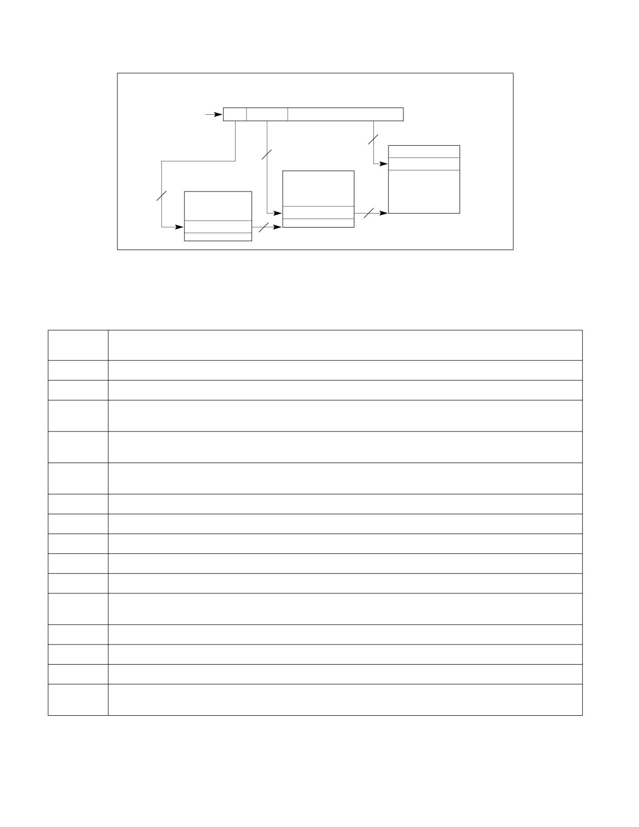
PAE paging may map linear addresses to either 4-KByte pages or 2-MByte pages. Figure 4-5 illustrates the trans-
lation process when it produces a 4-KByte page; Figure 4-6 covers the case of a 2-MByte page. The following items
describe the PAE paging process in more detail as well has how the page size is determined:
• Bits 31:30 of the linear address select a PDPTE register (see Section 4.4.1); this is PDPTEi, where i is the value
of bits 31:30.1 Because a PDPTE register is identified using bits 31:30 of the linear address, it controls access
to a 1-GByte region of the linear-address space. If the P flag (bit 0) of PDPTEi is 0, the processor ignores bits
63:1, and there is no mapping for the 1-GByte region controlled by PDPTEi. A reference using a linear address
in this region causes a page-fault exception (see Section 4.7).
• If the P flag of PDPTEi is 1, 4-KByte naturally aligned page directory is located at the physical address specified
in bits 51:12 of PDPTEi (see Table 4-8 in Section 4.4.1). A page directory comprises 512 64-bit entries (PDEs).
A PDE is selected using the physical address defined as follows:
- Bits 51:12 are from PDPTEi.
- Bits 11:3 are bits 29:21 of the linear address.
- Bits 2:0 are 0.
Because a PDE is identified using bits 31:21 of the linear address, it controls access to a 2-Mbyte region of the
linear-address space. Use of the PDE depends on its PS flag (bit 7):
• If the PDE’s PS flag is 1, the PDE maps a 2-MByte page (see Table 4-9). The final physical address is computed
as follows:
- Bits 51:21 are from the PDE.
- Bits 20:0 are from the original linear address.
• If the PDE’s PS flag is 0, a 4-KByte naturally aligned page table is located at the physical address specified in
bits 51:12 of the PDE (see Table 4-10). A page table comprises 512 64-bit entries (PTEs). A PTE is selected
using the physical address defined as follows:
- Bits 51:12 are from the PDE.
1. With PAE paging, the processor does not use CR3 when translating a linear address (as it does in the other paging modes). It does
not access the PDPTEs in the page-directory-pointer table during linear-address translation.
Vol. 3A
4-15
PAGING
- Bits 11:3 are bits 20:12 of the linear address.
- Bits 2:0 are 0.
• Because a PTE is identified using bits 31:12 of the linear address, every PTE maps a 4-KByte page (see
Table 4-11). The final physical address is computed as follows:
- Bits 51:12 are from the PTE.
- Bits 11:0 are from the original linear address.
If the P flag (bit 0) of a PDE or a PTE is 0 or if a PDE or a PTE sets any reserved bit, the entry is used neither to
reference another paging-structure entry nor to map a page. There is no translation for a linear address whose
translation would use such a paging-structure entry; a reference to such a linear address causes a page-fault
exception (see Section 4.7).
The following bits are reserved with PAE paging:
• If the P flag (bit 0) of a PDE or a PTE is 1, bits 62:MAXPHYADDR are reserved.
• If the P flag and the PS flag (bit 7) of a PDE are both 1, bits 20:13 are reserved.
• If IA32_EFER.NXE = 0 and the P flag of a PDE or a PTE is 1, the XD flag (bit 63) is reserved.
• If the PAT is not supported:1
- If the P flag of a PTE is 1, bit 7 is reserved.
- If the P flag and the PS flag of a PDE are both 1, bit 12 is reserved.
A reference using a linear address that is successfully translated to a physical address is performed only if allowed
by the access rights of the translation; see Section 4.6.
Linear Address
31
30 29
21 20
12 11
0
Directory Pointer
Directory
Table
Offset
12
4-KByte Page
Page Table
Physical Address
Page Directory
9
PTE
9
40
PDE with PS=0
2
40
PDPTE Registers
40
PDPTE value
Figure 4-5. Linear-Address Translation to a 4-KByte Page using PAE Paging
1. See Section 4.1.4 for how to determine whether the PAT is supported.
4-16
Vol. 3A
PAGING
Linear Address
31
30 29
21 20
0
Directory
Directory
Offset
Pointer
2-MByte Page
21
9
Page Directory
Physical Address
PDPTE Registers
2
PDE with PS=1
31
PDPTE value
40
Figure 4-6. Linear-Address Translation to a 2-MByte Page using PAE Paging
Table 4-9. Format of a PAE Page-Directory Entry that Maps a 2-MByte Page
Bit
Contents
Position(s)
0 (P)
Present; must be 1 to map a 2-MByte page
1 (R/W)
Read/write; if 0, writes may not be allowed to the 2-MByte page referenced by this entry (see Section 4.6)
2 (U/S)
User/supervisor; if 0, user-mode accesses are not allowed to the 2-MByte page referenced by this entry (see Section
4.6)
3 (PWT)
Page-level write-through; indirectly determines the memory type used to access the 2-MByte page referenced by
this entry (see Section 4.9)
4 (PCD)
Page-level cache disable; indirectly determines the memory type used to access the 2-MByte page referenced by this
entry (see Section 4.9)
5 (A)
Accessed; indicates whether software has accessed the 2-MByte page referenced by this entry (see Section 4.8)
6 (D)
Dirty; indicates whether software has written to the 2-MByte page referenced by this entry (see Section 4.8)
7 (PS)
Page size; must be 1 (otherwise, this entry references a page table; see Table 4-10)
8 (G)
Global; if CR4.PGE = 1, determines whether the translation is global (see Section 4.10); ignored otherwise
11:9
Ignored
12 (PAT)
If the PAT is supported, indirectly determines the memory type used to access the 2-MByte page referenced by this
entry (see Section 4.9.2); otherwise, reserved (must be 0)1
20:13
Reserved (must be 0)
(M-1):21
Physical address of the 2-MByte page referenced by this entry
62:M
Reserved (must be 0)
63 (XD)
If IA32_EFER.NXE = 1, execute-disable (if 1, instruction fetches are not allowed from the 2-MByte page controlled by
this entry; see Section 4.6); otherwise, reserved (must be 0)
NOTES:
1. See Section 4.1.4 for how to determine whether the PAT is supported.
Vol. 3A
4-17

PAGING
Table 4-10. Format of a PAE Page-Directory Entry that References a Page Table
Bit
Contents
Position(s)
0 (P)
Present; must be 1 to reference a page table
1 (R/W)
Read/write; if 0, writes may not be allowed to the 2-MByte region controlled by this entry (see Section 4.6)
2 (U/S)
User/supervisor; if 0, user-mode accesses are not allowed to the 2-MByte region controlled by this entry (see
Section 4.6)
3 (PWT)
Page-level write-through; indirectly determines the memory type used to access the page table referenced by this
entry (see Section 4.9)
4 (PCD)
Page-level cache disable; indirectly determines the memory type used to access the page table referenced by this
entry (see Section 4.9)
5 (A)
Accessed; indicates whether this entry has been used for linear-address translation (see Section 4.8)
6
Ignored
7 (PS)
Page size; must be 0 (otherwise, this entry maps a 2-MByte page; see Table 4-9)
11:8
Ignored
(M-1):12
Physical address of 4-KByte aligned page table referenced by this entry
62:M
Reserved (must be 0)
63 (XD)
If IA32_EFER.NXE = 1, execute-disable (if 1, instruction fetches are not allowed from the 2-MByte region controlled
by this entry; see Section 4.6); otherwise, reserved (must be 0)
Table 4-11. Format of a PAE Page-Table Entry that Maps a 4-KByte Page
Bit
Contents
Position(s)
0 (P)
Present; must be 1 to map a 4-KByte page
1 (R/W)
Read/write; if 0, writes may not be allowed to the 4-KByte page referenced by this entry (see Section 4.6)
2 (U/S)
User/supervisor; if 0, user-mode accesses are not allowed to the 4-KByte page referenced by this entry (see Section
4.6)
3 (PWT)
Page-level write-through; indirectly determines the memory type used to access the 4-KByte page referenced by
this entry (see Section 4.9)
4 (PCD)
Page-level cache disable; indirectly determines the memory type used to access the 4-KByte page referenced by this
entry (see Section 4.9)
5 (A)
Accessed; indicates whether software has accessed the 4-KByte page referenced by this entry (see Section 4.8)
6 (D)
Dirty; indicates whether software has written to the 4-KByte page referenced by this entry (see Section 4.8)
7 (PAT)
If the PAT is supported, indirectly determines the memory type used to access the 4-KByte page referenced by this
entry (see Section 4.9.2); otherwise, reserved (must be 0)1
8 (G)
Global; if CR4.PGE = 1, determines whether the translation is global (see Section 4.10); ignored otherwise
4-18
Vol. 3A

PAGING
Table 4-11. Format of a PAE Page-Table Entry that Maps a 4-KByte Page (Contd.)
Bit
Contents
Position(s)
11:9
Ignored
(M-1):12
Physical address of the 4-KByte page referenced by this entry
62:M
Reserved (must be 0)
63 (XD)
If IA32_EFER.NXE = 1, execute-disable (if 1, instruction fetches are not allowed from the 4-KByte page controlled by
this entry; see Section 4.6); otherwise, reserved (must be 0)
NOTES:
1. See Section 4.1.4 for how to determine whether the PAT is supported.
Figure 4-7 gives a summary of the formats of CR3 and the paging-structure entries with PAE paging. For the paging
structure entries, it identifies separately the format of entries that map pages, those that reference other paging
structures, and those that do neither because they are “not present”; bit 0 (P) and bit 7 (PS) are highlighted
because they determine how a paging-structure entry is used.
6
6
6
6
5
5
5
5
5
5
5
5
5
3
3
3
2
2
2
2
2
2
2
2
2
2
1
1
1
1
1
1
1
1
1
1
M1
M-1
3
2
1
0
9
8
7
6
5
4
3
2
1
2
1
0
9
8
7
6
5
4
3
2
1
0
9
8
7
6
5
4
3
2
1
0
9
8
7
6
5
4
3
2
1
0
Ignored2
Address of page-directory-pointer table
Ignored
CR3
P
P
Rs
PDPTE:
Reserved3
Address of page directory
Ign.
Rsvd.
C
W
1
vd
present
D
T
PDTPE:
Ignored
0
not
present
X
P
P
P
R
PDE:
Address of
U
D
Reserved
Reserved
A
Ign.
G
1
D
A
C
W
/
1
2MB
4
2MB page frame
/S
T
D
T
W
page
I
P
P
R
PDE:
X
U
Reserved
Address of page table
Ign.
0
g
A
C
W
/
1
page
D
/S
n
D
T
W
table
PDE:
Ignored
0
not
present
P
P
P
R
PTE:
X
U
Reserved
Address of 4KB page frame
Ign.
G
A
D
A
C
W
/
1
4KB
D
/S
T
D
T
W
page
PTE:
Ignored
0
not
present
Figure 4-7. Formats of CR3 and Paging-Structure Entries with PAE Paging
NOTES:
1. M is an abbreviation for MAXPHYADDR.
2. CR3 has 64 bits only on processors supporting the Intel-64 architecture. These bits are ignored with PAE paging.
3. Reserved fields must be 0.
4. If IA32_EFER.NXE = 0 and the P flag of a PDE or a PTE is 1, the XD flag (bit 63) is reserved.
Vol. 3A
4-19
PAGING
4.5
4-LEVEL PAGING AND 5-LEVEL PAGING
Because the operation of 4-level paging and 5-level paging is very similar, they are described together in this
section. The following items highlight the distinctions between the two paging modes:
• A logical processor uses 4-level paging if CR0.PG = 1, CR4.PAE = 1, IA32_EFER.LME = 1, and CR4.LA57 = 0.
4-level paging translates 48-bit linear addresses to 52-bit physical addresses.1 Although 52 bits corresponds to
4 PBytes, linear addresses are limited to 48 bits; at most 256 TBytes of linear-address space may be accessed
at any given time.
• A logical processor uses 5-level paging if CR0.PG = 1, CR4.PAE = 1, IA32_EFER.LME = 1, and CR4.LA57 = 1.
5-level paging translates 57-bit linear addresses to 52-bit physical addresses. Thus, 5-level paging supports a
linear-address space sufficient to access the entire physical-address space.
4.5.1
Ordinary Paging and HLAT Paging
There are two forms of 4-level paging and 5-level paging that differ principally with regard to how linear-address
translation identifies the first paging structure.
The normal form is called ordinary paging, and it uses CR3 to locate the first paging structure, similar to what is
done for 32-bit paging. Section 4.5.2 provides details of this use of CR3.
An alternative form of paging may be used with the VMX feature called hypervisor-managed linear-address trans-
lation (HLAT). Called HLAT paging, this form is used only in VMX non-root operation and only if the “enable HLAT”
VM-execution control is 1.2 HLAT paging locates the first paging structure using a VM-execution control field in the
VMCS called the HLAT pointer (HLATP). Section 4.5.3 provides details.
Whether HLAT paging is used to translate a specific linear address depends on the address and on the value of a
VM-execution control field in the VMCS called the HLAT prefix size:
• If the HLAT prefix size is zero, every linear address is translated using HLAT paging.
• If the HLAT prefix size is not zero, a linear address is translated using HLAT paging if bit 63 of the address is 1.3
The address is translated using ordinary paging if bit 63 of the address is 0.
In some cases, HLAT paging may specify that a translation of a linear address must be restarted. When this occurs,
the linear address is then translated using ordinary paging (starting with a paging structure identified using CR3).
The situations leading to this restart are detailed in Section 4.5.4, and additional details of the restart process are
given in Section 4.5.5.
4.5.2
Use of CR3 with Ordinary 4-Level Paging and 5-Level Paging
Ordinary 4-level paging and 5-level paging each translate linear addresses using a hierarchy of in-memory paging
structures located using the contents of CR3, which is used to locate the first paging structure. For 4-level paging,
this is the PML4 table, and for 5-level paging it is the PML5 table. Use of CR3 with 4-level paging and 5-level paging
depends on whether process-context identifiers (PCIDs) have been enabled by setting CR4.PCIDE:
• Table 4-12 illustrates how CR3 is used with 4-level paging and 5-level paging if CR4.PCIDE = 0.
Table 4-12. Use of CR3 with 4-Level Paging and 5-level Paging and CR4.PCIDE = 0
Bit
Contents
Position(s)
2:0
Ignored
1. If MAXPHYADDR < 52, bits in the range 51:MAXPHYADDR will be 0 in any physical address used by 4-level paging. (The correspond-
ing bits are reserved in the paging-structure entries.) See Section 4.1.4 for how to determine MAXPHYADDR.
2. HLAT paging is used only with 4-level paging and 5-level paging. It is never used with 32-bit paging or PAE paging, regardless of the
value of the “enable HLAT” VM-execution control.
3. This behavior applies if the CPU enumerates a maximum HLAT prefix size of 1 in IA32_VMX_EPT_VPID_CAP[53:48] (see Appendix
A.10). Behavior when a different value is enumerated is not currently defined.
4-20
Vol. 3A
PAGING
Table 4-12. Use of CR3 with 4-Level Paging and 5-level Paging and CR4.PCIDE = 0 (Contd.)
Bit
Contents
Position(s)
3 (PWT)
Page-level write-through; indirectly determines the memory type used to access the PML4 table or PML5 table
during linear-address translation (see Section 4.9.2)
4 (PCD)
Page-level cache disable; indirectly determines the memory type used to access the PML4 table or PML5 table during
linear-address translation (see Section 4.9.2)
11:5
Ignored
M-1:12
Physical address of the 4-KByte aligned PML4 table or PML5 table used for linear-address translation1
63:M
Reserved (must be 0)
NOTES:
1. M is an abbreviation for MAXPHYADDR, which is at most 52; see Section 4.1.4.
• Table 4-13 illustrates how CR3 is used with 4-level paging and 5-level paging if CR4.PCIDE = 1.
Table 4-13. Use of CR3 with 4-Level Paging and 5-Level Paging and CR4.PCIDE = 1
Bit
Contents
Position(s)
11:0
PCID (see Section 4.10.1)1
M-1:12
Physical address of the 4-KByte aligned PML4 table used for linear-address translation2
63:M
Reserved (must be 0)3
NOTES:
1. Section 4.9.2 explains how the processor determines the memory type used to access the PML4 table during linear-address transla-
tion with CR4.PCIDE = 1.
2. M is an abbreviation for MAXPHYADDR, which is at most 52; see Section 4.1.4.
3. See Section 4.10.4.1 for use of bit 63 of the source operand of the MOV to CR3 instruction.
After software modifies the value of CR4.PCIDE, the logical processor immediately begins using CR3 as specified
for the new value. For example, if software changes CR4.PCIDE from 1 to 0, the current PCID immediately changes
from CR3[11:0] to 000H (see also Section 4.10.4.1). In addition, the logical processor subsequently determines
the memory type used to access the PML4 table using CR3.PWT and CR3.PCD, which had been bits 4:3 of the PCID.
4.5.3
Use of HLATP with HLAT 4-Level Paging and 5-Level Paging
With HLAT paging, 4-level paging and 5-level paging each translate linear addresses using a hierarchy of in-
memory paging structures located using the value of HLATP (a VM-execution control field in the VMCS), which is
used to locate the first paging structure. For 4-level paging, this is the PML4 table, and for 5-level paging it is the
PML5 table.
HLATP has the same format as that given for CR3 in Table 4-12, with the exception that bits 2:0 and bits 11:5 are
reserved and must be zero (these bits are checked by VM entry). HLATP does not contain a PCID value. HLAT
paging with CR4.PCIDE = 1 uses the PCID value in CR3[11:0].
Vol. 3A
4-21
PAGING
4.5.4
Linear-Address Translation with 4-Level Paging and 5-Level Paging
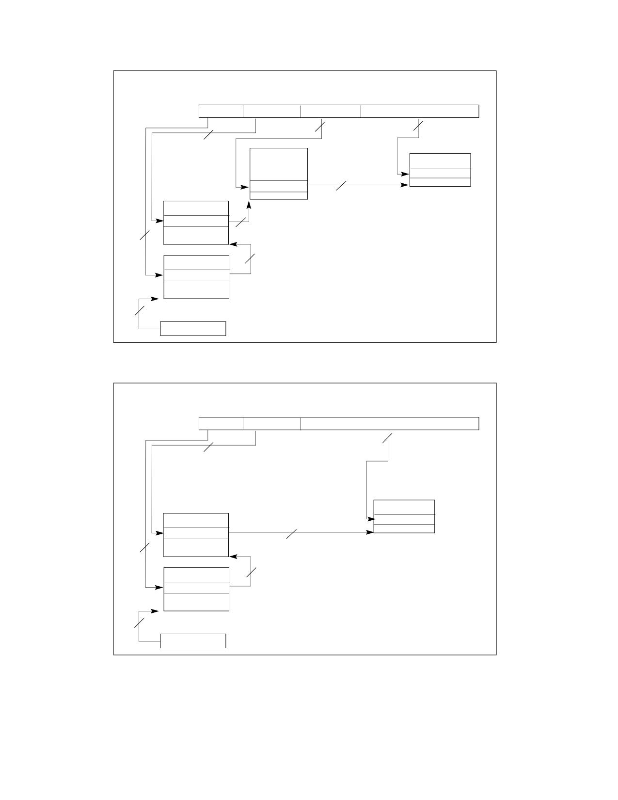
4-level paging and 5-level paging may map linear addresses to 4-KByte pages, 2-MByte pages, or 1-GByte pages.1
Figure 4-8 illustrates the translation process for 4-level paging when it produces a 4-KByte page; Figure 4-9 covers
the case of a 2-MByte page, and Figure 4-10 the case of a 1-GByte page. (The process for 5-level paging is similar.)
Linear Address
47
39 38
30 29
21 20
12
11
0
PML4
Directory Ptr
Directory
Table
Offset
9
9
9
4-KByte Page
12
Physical Addr
PTE
40
Page-Directory-
PDE with PS=0
Pointer Table
40
Page Table
Page-Directory
40
PDPTE
9
40
PML4E
40
CR3 or HLATP
Figure 4-8. Linear-Address Translation to a 4-KByte Page Using 4-Level Paging
1. Not all processors support 1-GByte pages; see Section 4.1.4.
4-22
Vol. 3A
PAGING
Linear Address
47
39 38
30 29
21
20
0
PML4
Directory Ptr
Directory
Offset
21
9
9
2-MByte Page
Physical Addr
Page-Directory-
PDE with PS=1
Pointer Table
31
Page-Directory
PDPTE
40
9
40
PML4E
40
CR3 or HLATP
Figure 4-9. Linear-Address Translation to a 2-MByte Page using 4-Level Paging
Linear Address
47
39 38
30 29
0
PML4
Directory Ptr
Offset
30
9
1-GByte Page
Page-Directory-
Pointer Table
Physical Addr
PDPTE with PS=1
22
9
40
PML4E
40
CR3 or HLATP
Figure 4-10. Linear-Address Translation to a 1-GByte Page using 4-Level Paging
Vol. 3A
4-23
PAGING
4-level paging and 5-level paging associate with each linear address a protection key. Section 4.6 explains how
the processor uses the protection key in its determination of the access rights of each linear address.
The remainder of this section describes the translation process used by 4-level paging and 5-level paging in more
detail, as well has how the page size and protection key are determined. Because the process used by the two
paging modes is similar, they are described together, with any differences identified, in the following items:
• With 5-level paging, a 4-KByte naturally aligned PML5 table is located at the physical address specified in
bits 51:12 of CR3 (see Table 4-12). (4-level paging does not use a PML5 table and omits this step.) A PML5
table comprises 512 64-bit entries (PML5Es). A PML5E is selected using the physical address defined as follows:
- Bits 51:12 are from CR3 or HLATP.
- Bits 11:3 are bits 56:48 of the linear address.
- Bits 2:0 are all 0.
Because a PML5E is identified using bits 56:48 of the linear address, it controls access to a 256-TByte region of
the linear-address space.
With HLAT paging, if bit 11 of the PML5E is 1, translation is restarted with ordinary paging with a maximum
page size of 256-TBytes (see Section 4.5.5). Otherwise, the translation process continues as described in the
next item.
• A 4-KByte naturally aligned PML4 table is located at the physical address specified in bits 51:12 of CR3 (for 4-
level paging; see Table 4-12) or in bits 51:12 of the PML5E (for 5-level paging; see Table 4-14). A PML4 table
comprises 512 64-bit entries (PML4Es). A PML4E is selected using the physical address defined as follows:
- Bits 51:12 are from CR3 or the HLATP (for 4-level paging) or in bits 51:12 of the PML5E (for 5-level
paging).
- Bits 11:3 are bits 47:39 of the linear address.
- Bits 2:0 are all 0.
Because a PML4E is identified using bits 47:39 of the linear address, it controls access to a 512-GByte region of
the linear-address space.
With HLAT paging, if bit 11 of the PML4E is 1, translation is restarted with ordinary paging with a maximum
page size of 512-GBytes (see Section 4.5.5). Otherwise, the translation process continues as described in the
next item.
• A 4-KByte naturally aligned page-directory-pointer table is located at the physical address specified in
bits 51:12 of the PML4E (see Table 4-15). A page-directory-pointer table comprises 512 64-bit entries
(PDPTEs). A PDPTE is selected using the physical address defined as follows:
- Bits 51:12 are from the PML4E.
- Bits 11:3 are bits 38:30 of the linear address.
- Bits 2:0 are all 0.
Because a PDPTE is identified using bits 47:30 of the linear address, it controls access to a 1-GByte region of the
linear-address space.
With HLAT paging, if bit 11 of the PDPTE is 1, translation is restarted with ordinary paging with a maximum page
size of 1-GByte (see Section 4.5.5). Otherwise, the translation process continues as described below.
Use of the PDPTE depends on its PS flag (bit 7):1
• If the PDPTE’s PS flag is 1, the PDPTE maps a 1-GByte page (see Table 4-16). The final physical address is
computed as follows:
- Bits 51:30 are from the PDPTE.
- Bits 29:0 are from the original linear address.
The linear address’s protection key is the value of bits 62:59 of the PDPTE (see Section 4.6.2).
1. The PS flag of a PDPTE is reserved and must be 0 (if the P flag is 1) if 1-GByte pages are not supported. See Section 4.1.4 for how
to determine whether 1-GByte pages are supported.
4-24
Vol. 3A
PAGING
• If the PDPTE’s PS flag is 0, a 4-KByte naturally aligned page directory is located at the physical address
specified in bits 51:12 of the PDPTE (see Table 4-17). A page directory comprises 512 64-bit entries (PDEs). A
PDE is selected using the physical address defined as follows:
- Bits 51:12 are from the PDPTE.
- Bits 11:3 are bits 29:21 of the linear address.
- Bits 2:0 are all 0.
Because a PDE is identified using bits 47:21 of the linear address, it controls access to a 2-MByte region of the
linear-address space.
With HLAT paging, if bit 11 of the PDE is 1, translation is restarted with ordinary paging with a maximum page size
of 2-MBytes (see Section 4.5.5). Otherwise, the translation process continues as described below.
Use of the PDE depends on its PS flag:
• If the PDE's PS flag is 1, the PDE maps a 2-MByte page (see Table 4-18). The final physical address is computed
as follows:
- Bits 51:21 are from the PDE.
- Bits 20:0 are from the original linear address.
The linear address’s protection key is the value of bits 62:59 of the PDE (see Section 4.6.2).
• If the PDE’s PS flag is 0, a 4-KByte naturally aligned page table is located at the physical address specified in
bits 51:12 of the PDE (see Table 4-19). A page table comprises 512 64-bit entries (PTEs). A PTE is selected
using the physical address defined as follows:
- Bits 51:12 are from the PDE.
- Bits 11:3 are bits 20:12 of the linear address.
- Bits 2:0 are all 0.
• Because a PTE is identified using bits 47:12 of the linear address, every PTE maps a 4-KByte page (see
Table 4-20).
With HLAT paging, if bit 11 of the PTE is 1, translation is restarted with ordinary paging with a maximum page
size of 4-KBytes (see Section 4.5.5). Otherwise, the final physical address is computed as follows:
- Bits 51:12 are from the PTE.
- Bits 11:0 are from the original linear address.
The linear address’s protection key is the value of bits 62:59 of the PTE (see Section 4.6.2).
If a paging-structure entry’s P flag (bit 0) is 0 or if the entry sets any reserved bit, the entry is used neither to refer-
ence another paging-structure entry nor to map a page. There is no translation for a linear address whose transla-
tion would use such a paging-structure entry; a reference to such a linear address causes a page-fault exception
(see Section 4.7).
The following bits in a paging-structure entry are reserved with 4-level paging and 5-level paging (assuming that
the entry’s P flag is 1):
• Bits 51:MAXPHYADDR are reserved in every paging-structure entry.
• The PS flag is reserved in a PML5E or a PML4E.
• If 1-GByte pages are not supported, the PS flag is reserved in a PDPTE.1
• If the PS flag in a PDPTE is 1, bits 29:13 of the entry are reserved.
• If the PS flag in a PDE is 1, bits 20:13 of the entry are reserved.
• If IA32_EFER.NXE = 0, the XD flag (bit 63) is reserved in every paging-structure entry.
A reference using a linear address that is successfully translated to a physical address is performed only if allowed
by the access rights of the translation; see Section 4.6.
1. See Section 4.1.4 for how to determine whether 1-GByte pages are supported.
Vol. 3A
4-25

PAGING
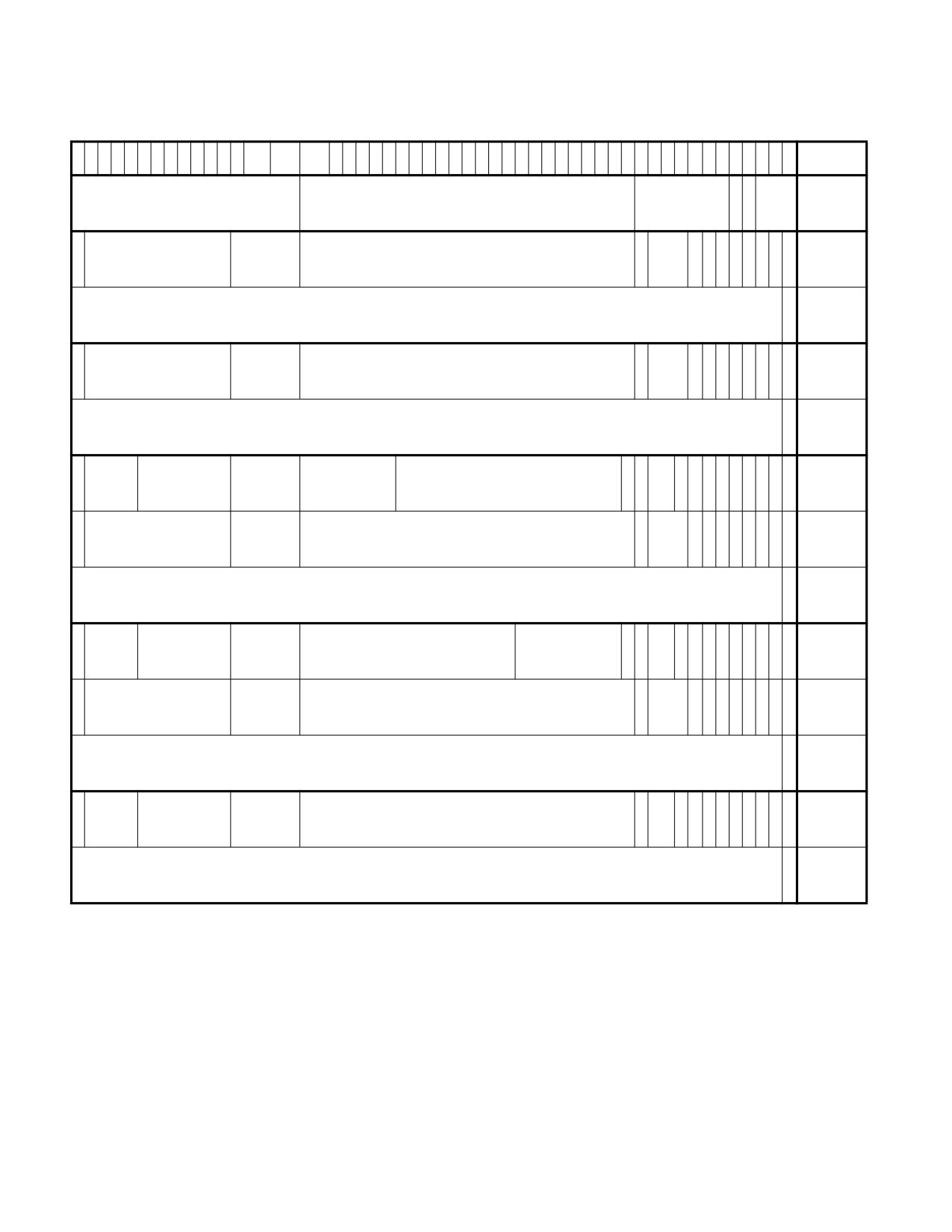
Figure 4-11 gives a summary of the formats of CR3 and the 4-level and 5-level paging-structure entries. For the
paging structure entries, it identifies separately the format of entries that map pages, those that reference other
paging structures, and those that do neither because they are “not present”; bit 0 (P) and bit 7 (PS) are highlighted
because they determine how a paging-structure entry is used.
Table 4-14. Format of a PML5 Entry (PML5E) that References a PML4 Table
Bit
Contents
Position(s)
0 (P)
Present; must be 1 to reference a PML4 table
1 (R/W)
Read/write; if 0, writes may not be allowed to the 256-TByte region controlled by this entry (see Section 4.6)
2 (U/S)
User/supervisor; if 0, user-mode accesses are not allowed to the 256-TByte region controlled by this entry (see
Section 4.6)
3 (PWT)
Page-level write-through; indirectly determines the memory type used to access the PML4 table referenced by this
entry (see Section 4.9.2)
4 (PCD)
Page-level cache disable; indirectly determines the memory type used to access the PML4 table referenced by this
entry (see Section 4.9.2)
5 (A)
Accessed; indicates whether this entry has been used for linear-address translation (see Section 4.8)
6
Ignored
7 (PS)
Reserved (must be 0)
10:8
Ignored
11 (R)
For ordinary paging, ignored; for HLAT paging, restart (if 1, linear-address translation is restarted with ordinary
paging)
M-1:12
Physical address of 4-KByte aligned PML4 table referenced by this entry
51:M
Reserved (must be 0)
62:52
Ignored
63 (XD)
If IA32_EFER.NXE = 1, execute-disable (if 1, instruction fetches are not allowed from the 256-TByte region
controlled by this entry; see Section 4.6); otherwise, reserved (must be 0)
Table 4-15. Format of a PML4 Entry (PML4E) that References a Page-Directory-Pointer Table
Bit
Contents
Position(s)
0 (P)
Present; must be 1 to reference a page-directory-pointer table
1 (R/W)
Read/write; if 0, writes may not be allowed to the 512-GByte region controlled by this entry (see Section 4.6)
2 (U/S)
User/supervisor; if 0, user-mode accesses are not allowed to the 512-GByte region controlled by this entry (see
Section 4.6)
3 (PWT)
Page-level write-through; indirectly determines the memory type used to access the page-directory-pointer table
referenced by this entry (see Section 4.9.2)
4 (PCD)
Page-level cache disable; indirectly determines the memory type used to access the page-directory-pointer table
referenced by this entry (see Section 4.9.2)
5 (A)
Accessed; indicates whether this entry has been used for linear-address translation (see Section 4.8)
6
Ignored
4-26
Vol. 3A

PAGING
Table 4-15. Format of a PML4 Entry (PML4E) that References a Page-Directory-Pointer Table (Contd.)
Bit
Contents
Position(s)
7 (PS)
Reserved (must be 0)
10:8
Ignored
11 (R)
For ordinary paging, ignored; for HLAT paging, restart (if 1, linear-address translation is restarted with ordinary
paging)
M-1:12
Physical address of 4-KByte aligned page-directory-pointer table referenced by this entry
51:M
Reserved (must be 0)
62:52
Ignored
63 (XD)
If IA32_EFER.NXE = 1, execute-disable (if 1, instruction fetches are not allowed from the 512-GByte region
controlled by this entry; see Section 4.6); otherwise, reserved (must be 0)
Table 4-16. Format of a Page-Directory-Pointer-Table Entry (PDPTE) that Maps a 1-GByte Page
Bit
Contents
Position(s)
0 (P)
Present; must be 1 to map a 1-GByte page
1 (R/W)
Read/write; if 0, writes may not be allowed to the 1-GByte page referenced by this entry (see Section 4.6)
2 (U/S)
User/supervisor; if 0, user-mode accesses are not allowed to the 1-GByte page referenced by this entry (see Section
4.6)
3 (PWT)
Page-level write-through; indirectly determines the memory type used to access the 1-GByte page referenced by this
entry (see Section 4.9.2)
4 (PCD)
Page-level cache disable; indirectly determines the memory type used to access the 1-GByte page referenced by this
entry (see Section 4.9.2)
5 (A)
Accessed; indicates whether software has accessed the 1-GByte page referenced by this entry (see Section 4.8)
6 (D)
Dirty; indicates whether software has written to the 1-GByte page referenced by this entry (see Section 4.8)
7 (PS)
Page size; must be 1 (otherwise, this entry references a page directory; see Table 4-17)
8 (G)
Global; if CR4.PGE = 1, determines whether the translation is global (see Section 4.10); ignored otherwise
10:9
Ignored
11 (R)
For ordinary paging, ignored; for HLAT paging, restart (if 1, linear-address translation is restarted with ordinary
paging)
12 (PAT)
Indirectly determines the memory type used to access the 1-GByte page referenced by this entry (see Section
4.9.2)1
29:13
Reserved (must be 0)
(M-1):30
Physical address of the 1-GByte page referenced by this entry
Vol. 3A
4-27

PAGING
Table 4-16. Format of a Page-Directory-Pointer-Table Entry (PDPTE) that Maps a 1-GByte Page (Contd.)
Bit
Contents
Position(s)
51:M
Reserved (must be 0)
58:52
Ignored
62:59
Protection key; if CR4.PKE = 1 or CR4.PKS = 1, this may control the page’s access rights (see Section 4.6.2); otherwise,
it is ignored and not used to control access rights.
63 (XD)
If IA32_EFER.NXE = 1, execute-disable (if 1, instruction fetches are not allowed from the 1-GByte page controlled by
this entry; see Section 4.6); otherwise, reserved (must be 0)
NOTES:
1. The PAT is supported on all processors that support 4-level paging.
Table 4-17. Format of a Page-Directory-Pointer-Table Entry (PDPTE) that References a Page Directory
Bit
Contents
Position(s)
0 (P)
Present; must be 1 to reference a page directory
1 (R/W)
Read/write; if 0, writes may not be allowed to the 1-GByte region controlled by this entry (see Section 4.6)
2 (U/S)
User/supervisor; if 0, user-mode accesses are not allowed to the 1-GByte region controlled by this entry (see Section
4.6)
3 (PWT)
Page-level write-through; indirectly determines the memory type used to access the page directory referenced by
this entry (see Section 4.9.2)
4 (PCD)
Page-level cache disable; indirectly determines the memory type used to access the page directory referenced by
this entry (see Section 4.9.2)
5 (A)
Accessed; indicates whether this entry has been used for linear-address translation (see Section 4.8)
6
Ignored
7 (PS)
Page size; must be 0 (otherwise, this entry maps a 1-GByte page; see Table 4-16)
10:8
Ignored
11 (R)
For ordinary paging, ignored; for HLAT paging, restart (if 1, linear-address translation is restarted with ordinary
paging)
(M-1):12
Physical address of 4-KByte aligned page directory referenced by this entry
51:M
Reserved (must be 0)
62:52
Ignored
63 (XD)
If IA32_EFER.NXE = 1, execute-disable (if 1, instruction fetches are not allowed from the 1-GByte region controlled
by this entry; see Section 4.6); otherwise, reserved (must be 0)
4-28
Vol. 3A

PAGING
Table 4-18. Format of a Page-Directory Entry that Maps a 2-MByte Page
Bit
Contents
Position(s)
0 (P)
Present; must be 1 to map a 2-MByte page
1 (R/W)
Read/write; if 0, writes may not be allowed to the 2-MByte page referenced by this entry (see Section 4.6)
2 (U/S)
User/supervisor; if 0, user-mode accesses are not allowed to the 2-MByte page referenced by this entry (see Section
4.6)
3 (PWT)
Page-level write-through; indirectly determines the memory type used to access the 2-MByte page referenced by
this entry (see Section 4.9.2)
4 (PCD)
Page-level cache disable; indirectly determines the memory type used to access the 2-MByte page referenced by
this entry (see Section 4.9.2)
5 (A)
Accessed; indicates whether software has accessed the 2-MByte page referenced by this entry (see Section 4.8)
6 (D)
Dirty; indicates whether software has written to the 2-MByte page referenced by this entry (see Section 4.8)
7 (PS)
Page size; must be 1 (otherwise, this entry references a page table; see Table 4-19)
8 (G)
Global; if CR4.PGE = 1, determines whether the translation is global (see Section 4.10); ignored otherwise
10:9
Ignored
11 (R)
For ordinary paging, ignored; for HLAT paging, restart (if 1, linear-address translation is restarted with ordinary
paging)
12 (PAT)
Indirectly determines the memory type used to access the 2-MByte page referenced by this entry (see Section
4.9.2)
20:13
Reserved (must be 0)
(M-1):21
Physical address of the 2-MByte page referenced by this entry
51:M
Reserved (must be 0)
58:52
Ignored
62:59
Protection key; if CR4.PKE = 1 or CR4.PKS = 1, this may control the page’s access rights (see Section 4.6.2);
otherwise, it is ignored and not used to control access rights.
63 (XD)
If IA32_EFER.NXE = 1, execute-disable (if 1, instruction fetches are not allowed from the 2-MByte page controlled by
this entry; see Section 4.6); otherwise, reserved (must be 0)
Vol. 3A
4-29

PAGING
Table 4-19. Format of a Page-Directory Entry that References a Page Table
Bit
Contents
Position(s)
0 (P)
Present; must be 1 to reference a page table
1 (R/W)
Read/write; if 0, writes may not be allowed to the 2-MByte region controlled by this entry (see Section 4.6)
2 (U/S)
User/supervisor; if 0, user-mode accesses are not allowed to the 2-MByte region controlled by this entry (see Section
4.6)
3 (PWT)
Page-level write-through; indirectly determines the memory type used to access the page table referenced by this
entry (see Section 4.9.2)
4 (PCD)
Page-level cache disable; indirectly determines the memory type used to access the page table referenced by this
entry (see Section 4.9.2)
5 (A)
Accessed; indicates whether this entry has been used for linear-address translation (see Section 4.8)
6
Ignored
7 (PS)
Page size; must be 0 (otherwise, this entry maps a 2-MByte page; see Table 4-18)
10:8
Ignored
11 (R)
For ordinary paging, ignored; for HLAT paging, restart (if 1, linear-address translation is restarted with ordinary
paging)
(M-1):12
Physical address of 4-KByte aligned page table referenced by this entry
51:M
Reserved (must be 0)
62:52
Ignored
63 (XD)
If IA32_EFER.NXE = 1, execute-disable (if 1, instruction fetches are not allowed from the 2-MByte region controlled
by this entry; see Section 4.6); otherwise, reserved (must be 0)
4-30
Vol. 3A

PAGING
Table 4-20. Format of a Page-Table Entry that Maps a 4-KByte Page
Bit
Contents
Position(s)
0 (P)
Present; must be 1 to map a 4-KByte page
1 (R/W)
Read/write; if 0, writes may not be allowed to the 4-KByte page referenced by this entry (see Section 4.6)
2 (U/S)
User/supervisor; if 0, user-mode accesses are not allowed to the 4-KByte page referenced by this entry (see Section
4.6)
3 (PWT)
Page-level write-through; indirectly determines the memory type used to access the 4-KByte page referenced by
this entry (see Section 4.9.2)
4 (PCD)
Page-level cache disable; indirectly determines the memory type used to access the 4-KByte page referenced by this
entry (see Section 4.9.2)
5 (A)
Accessed; indicates whether software has accessed the 4-KByte page referenced by this entry (see Section 4.8)
6 (D)
Dirty; indicates whether software has written to the 4-KByte page referenced by this entry (see Section 4.8)
7 (PAT)
Indirectly determines the memory type used to access the 4-KByte page referenced by this entry (see Section 4.9.2)
8 (G)
Global; if CR4.PGE = 1, determines whether the translation is global (see Section 4.10); ignored otherwise
10:9
Ignored
11 (R)
For ordinary paging, ignored; for HLAT paging, restart (if 1, linear-address translation is restarted with ordinary
paging)
(M-1):12
Physical address of the 4-KByte page referenced by this entry
51:M
Reserved (must be 0)
58:52
Ignored
62:59
Protection key; if CR4.PKE = 1 or CR4.PKS = 1, this may control the page’s access rights (see Section 4.6.2);
otherwise, it is ignored and not used to control access rights.
63 (XD)
If IA32_EFER.NXE = 1, execute-disable (if 1, instruction fetches are not allowed from the 4-KByte page controlled by
this entry; see Section 4.6); otherwise, reserved (must be 0)
Vol. 3A
4-31
PAGING
6
6
6
6
5
5
5
5
5
5
5
5
5
3
3
3
2
2
2
2
2
2
2
2
2
2
1
1
1
1
1
1
1
1
1
1
M1
M-1
3
2
1
0
9
8
7
6
5
4
3
2
1
2
1
0
9
8
7
6
5
4
3
2
1
0
9
8
7
6
5
4
3
2
1
0
9
8
7
6
5
4
3
2
1
0
P
P
Address of PML4 table (4-level paging)
Reserved2
Ignored
C
W
Ign.
CR3
or PML5 table (5-level paging)
D
T
X
I
P
P
R
R
Rs
U
PML5E:
D
Ignored
Rsvd.
Address of PML4 table
4
Ign.
g
A
C
W
/
1
vd
/S
present
3
n
D
T
W
PML5E:
Ignored
0
not
present
I
P
P
R
X
Rs
U
PML4E:
Ignored
Rsvd.
Address of page-directory-pointer table
R
Ign.
g
A
C
W
/
1
D
vd
/S
present
n
D
T
W
PML4E:
Ignored
0
not
present
P
P
P
R
PDPTE:
X
Prot.
Address of
U
Ignored
Rsvd.
Reserved
A
R
Ign.
G
1
D
A
C
W
/
1
1GB
D
Key5
1GB page frame
/S
T
D
T
W
page
I
P
P
R
PDPTE:
X
U
Ignored
Rsvd.
Address of page directory
R
Ign.
0
g
A
C
W
/
1
page
D
/S
n
D
T
W
directory
PDTPE:
Ignored
0
not
present
P
P
P
R
PDE:
X
Prot.
Address of
U
Ignored
Rsvd.
Reserved
A
R
Ign.
G
1
D
A
C
W
/
1
2MB
D
Key
2MB page frame
/S
T
D
T
W
page
I
P
P
R
PDE:
X
U
Ignored
Rsvd.
Address of page table
R
Ign.
0
g
A
C
W
/
1
page
D
/S
n
D
T
W
table
PDE:
Ignored
0
not
present
P
P
P
R
PTE:
X
Prot.
U
Ignored
Rsvd.
Address of 4KB page frame
R
Ign.
G
A
D
A
C
W
/
1
4KB
D
Key
/S
T
D
T
W
page
PTE:
Ignored
0
not
present
Figure 4-11. Formats of CR3 and Paging-Structure Entries with 4-Level Paging and 5-Level Paging
NOTES:
1. M is an abbreviation for MAXPHYADDR.
2. Reserved fields must be 0.
3. If IA32_EFER.NXE = 0 and the P flag of a paging-structure entry is 1, the XD flag (bit 63) is reserved.
4. Bit 11 is R (restart) only for HLAT paging; it is ignored for ordinary paging.
5. The protection key is used only if software has enabled the appropriate feature; see Section 4.6.2. It is ignored otherwise.
4-32
Vol. 3A
PAGING
4.5.5
Restart of HLAT Paging
As noted in Section 4.5.1, HLAT paging may specify that a translation of a linear address must be restarted. Specif-
ically, this occurs when HLAT paging encounters a paging-structure entry that sets bit 11 (see Section 4.5.4).
When this occurs, translation of the linear address is restarted using ordinary paging (starting with a paging struc-
ture identified using CR3). The restarted translation proceeds just as if the HLAT feature were not enabled. The
entire linear address is translated again, including those portions that had been used by HLAT paging prior to the
restart.
The process of restarting HLAT paging (using ordinary paging) always specifies a maximum page size to be used
when a resulting translation is cached in the TLBs. This maximum page size depends on the level of the paging-
structure entry that restarts the translation by setting bit 11; details are given in Section 4.5.4. The page size of
the translation produced by the restarted process is never greater than this maximum page size. See Section
4.10.2.2 for more discussion.
4.6
ACCESS RIGHTS
There is a translation for a linear address if the processes described in Section 4.3, Section 4.4.2, and Section 4.5
(depending upon the paging mode) completes and produces a physical address. Whether an access is permitted by
a translation is determined by the access rights specified by the paging-structure entries controlling the transla-
tion;1 paging-mode modifiers in CR0, CR4, and the IA32_EFER MSR; EFLAGS.AC; and the mode of the access.
Section 4.6.1 describes how the processor determines the access rights for each linear address. Section 4.6.2
provides additional information about how protection keys contribute to access-rights determination. (They do so
only with 4-level paging and 5-level paging, and only if CR4.PKE = 1 or CR4.PKS = 1.)
NOTE
If HLAT paging is restarted, permissions are determined only by the access rights specified by the
paging-structure entries that the subsequent ordinary paging used to translate the linear address.
The access rights specified by the entries used earlier by HLAT paging do not apply.
4.6.1
Determination of Access Rights
Every access to a linear address is either a supervisor-mode access or a user-mode access. For all instruction
fetches and most data accesses, this distinction is determined by the current privilege level (CPL): accesses made
while CPL < 3 are supervisor-mode accesses, while accesses made while CPL = 3 are user-mode accesses.
Some operations implicitly access system data structures with linear addresses; the resulting accesses to those
data structures are supervisor-mode accesses regardless of CPL. Examples of such accesses include the following:
accesses to the global descriptor table (GDT) or local descriptor table (LDT) to load a segment descriptor; accesses
to the interrupt descriptor table (IDT) when delivering an interrupt or exception; and accesses to the task-state
segment (TSS) as part of a task switch or change of CPL. All these accesses are called implicit supervisor-mode
accesses regardless of CPL. Other accesses made while CPL < 3 are called explicit supervisor-mode accesses.
Access rights are also controlled by the mode of a linear address as specified by the paging-structure entries
controlling the translation of the linear address. If the U/S flag (bit 2) is 0 in at least one of the paging-structure
entries, the address is a supervisor-mode address. Otherwise, the address is a user-mode address.
When the shadow-stack feature of control-flow enforcement technology (CET) is enabled, certain accesses to
linear addresses are considered shadow-stack accesses (see Section 17.2, “Shadow Stacks,” in the Intel® 64
and IA-32 Architectures Software Developer’s Manual, Volume 1). Like ordinary data accesses, each shadow-stack
access is defined as being either a user access or a supervisor access. In general, a shadow-stack access is a user
access if CPL = 3 and a supervisor access if CPL < 3. The WRUSS instruction is an exception; although it can be
executed only if CPL = 0, the processor treats its shadow-stack accesses as user accesses.
1. With PAE paging, the PDPTEs do not determine access rights.
Vol. 3A
4-33
PAGING
Shadow-stack accesses are allowed only to shadow-stack addresses. A linear address is a shadow-stack
address if the following are true of the translation of the linear address: (1) the R/W flag (bit 1) is 0 and the dirty
flag (bit 6) is 1 in the paging-structure entry that maps the page containing the linear address; and (2) the R/W
flag is 1 in every other paging-structure entry controlling the translation of the linear address.
The following items detail how paging determines access rights (only the items noted explicitly apply to shadow-
stack accesses):
NOTE
Many of the items below refer to an address with a protection key for which read (or write) access
is permitted. Section 4.6.2 provides details on when a protection key will permit (or not permit) a
data access (read or write) to a linear address using that protection key.
• For supervisor-mode accesses:
- Data may be read (implicitly or explicitly) from any supervisor-mode address with a protection key for
which read access is permitted.
- Data reads from user-mode pages.
Access rights depend on the value of CR4.SMAP:
• If CR4.SMAP = 0, data may be read from any user-mode address with a protection key for which read
access is permitted.
• If CR4.SMAP = 1, access rights depend on the value of EFLAGS.AC and whether the access is implicit or
explicit:
- If EFLAGS.AC = 1 and the access is explicit, data may be read from any user-mode address with a
protection key for which read access is permitted.
- If EFLAGS.AC = 0 or the access is implicit, data may not be read from any user-mode address.
- Data writes to supervisor-mode addresses.
Access rights depend on the value of CR0.WP:
• If CR0.WP = 0, data may be written to any supervisor-mode address with a protection key for which
write access is permitted.
• If CR0.WP = 1, data may be written to any supervisor-mode address with a translation for which the
R/W flag (bit 1) is 1 in every paging-structure entry controlling the translation and with a protection key
for which write access is permitted; data may not be written to any supervisor-mode address with a
translation for which the R/W flag is 0 in any paging-structure entry controlling the translation.
- Data writes to user-mode addresses.
Access rights depend on the value of CR0.WP:
• If CR0.WP = 0, access rights depend on the value of CR4.SMAP:
- If CR4.SMAP = 0, data may be written to any user-mode address with a protection key for which
write access is permitted.
- If CR4.SMAP = 1, access rights depend on the value of EFLAGS.AC and whether the access is
implicit or explicit:
• If EFLAGS.AC = 1 and the access is explicit, data may be written to any user-mode address
with a protection key for which write access is permitted.
• If EFLAGS.AC = 0 or the access is implicit, data may not be written to any user-mode address.
• If CR0.WP = 1, access rights depend on the value of CR4.SMAP:
- If CR4.SMAP = 0, data may be written to any user-mode address with a translation for which the
R/W flag is 1 in every paging-structure entry controlling the translation and with a protection key
for which write access is permitted; data may not be written to any user-mode address with a
translation for which the R/W flag is 0 in any paging-structure entry controlling the translation.
- If CR4.SMAP = 1, access rights depend on the value of EFLAGS.AC and whether the access is
implicit or explicit:
4-34
Vol. 3A
PAGING
• If EFLAGS.AC = 1 and the access is explicit, data may be written to any user-mode address
with a translation for which the R/W flag is 1 in every paging-structure entry controlling the
translation and with a protection key for which write access is permitted; data may not be
written to any user-mode address with a translation for which the R/W flag is 0 in any paging-
structure entry controlling the translation.
• If EFLAGS.AC = 0 or the access is implicit, data may not be written to any user-mode address.
- Instruction fetches from supervisor-mode addresses.
• For 32-bit paging or if IA32_EFER.NXE = 0, instructions may be fetched from any supervisor-mode
address.
• For other paging modes with IA32_EFER.NXE = 1, instructions may be fetched from any supervisor-
mode address with a translation for which the XD flag (bit 63) is 0 in every paging-structure entry
controlling the translation; instructions may not be fetched from any supervisor-mode address with a
translation for which the XD flag is 1 in any paging-structure entry controlling the translation.
- Instruction fetches from user-mode addresses.
Access rights depend on the values of CR4.SMEP:
• If CR4.SMEP = 0, access rights depend on the paging mode and the value of IA32_EFER.NXE:
- For 32-bit paging or if IA32_EFER.NXE = 0, instructions may be fetched from any user-mode
address.
- For other paging modes with IA32_EFER.NXE = 1, instructions may be fetched from any user-
mode address with a translation for which the XD flag is 0 in every paging-structure entry
controlling the translation; instructions may not be fetched from any user-mode address with a
translation for which the XD flag is 1 in any paging-structure entry controlling the translation.
• If CR4.SMEP = 1, instructions may not be fetched from any user-mode address.
- Supervisor-mode shadow-stack accesses are allowed only to supervisor-mode shadow-stack addresses
(see above).
• For user-mode accesses:
- Data reads.
Access rights depend on the mode of the linear address:
• Data may be read from any user-mode address with a protection key for which read access is
permitted.
• Data may not be read from any supervisor-mode address.
- Data writes.
Access rights depend on the mode of the linear address:
• Data may be written to any user-mode address with a translation for which the R/W flag is 1 in every
paging-structure entry controlling the translation and with a protection key for which write access is
permitted.
• Data may not be written to any supervisor-mode address.
- Instruction fetches.
Access rights depend on the mode of the linear address, the paging mode, and the value of
IA32_EFER.NXE:
• For 32-bit paging or if IA32_EFER.NXE = 0, instructions may be fetched from any user-mode address.
• For other paging modes with IA32_EFER.NXE = 1, instructions may be fetched from any user-mode
address with a translation for which the XD flag is 0 in every paging-structure entry controlling the
translation.
• Instructions may not be fetched from any supervisor-mode address.
- User-mode shadow-stack accesses made outside enclave mode are allowed only to user-mode shadow-
stack addresses (see above). User-mode shadow-stack accesses made in enclave mode are treated like
ordinary data accesses (see above).
Vol. 3A
4-35
PAGING
A processor may cache information from the paging-structure entries in TLBs and paging-structure caches (see
Section 4.10). These structures may include information about access rights. The processor may enforce access
rights based on the TLBs and paging-structure caches instead of on the paging structures in memory.
This fact implies that, if software modifies a paging-structure entry to change access rights, the processor might
not use that change for a subsequent access to an affected linear address (see Section 4.10.4.3). See Section
4.10.4.2 for how software can ensure that the processor uses the modified access rights.
4.6.2
Protection Keys
4-level paging and 5-level paging associate a 4-bit protection key with each linear address (the protection key
located in bits 62:59 of the paging-structure entry that mapped the page containing the linear address; see Section
4.5). Two protection key features control accesses to linear addresses based on their protection keys:
• If CR4.PKE = 1, the PKRU register determines, for each protection key, whether user-mode addresses with that
protection key may be read or written.
• If CR4.PKS = 1, the IA32_PKRS MSR (MSR index 6E1H) determines, for each protection key, whether
supervisor-mode addresses with that protection key may be read or written.
32-bit paging and PAE paging do not associate linear addresses with protection keys. For the purposes of Section
4.6.1, reads and writes are implicitly permitted for all protection keys with either of those paging modes.
The PKRU register (protection-key rights for user pages) is a 32-bit register with the following format: for each i
(0 ≤ i ≤ 15), PKRU[2i] is the access-disable bit for protection key i (ADi); PKRU[2i+1] is the write-disable bit
for protection key i (WDi). The IA32_PKRS MSR has the same format (bits 63:32 of the MSR are reserved and must
be zero).
Software can use the RDPKRU and WRPKRU instructions with ECX = 0 to read and write PKRU. In addition, the
PKRU register is XSAVE-managed state and can thus be read and written by instructions in the XSAVE feature set.
See Chapter 13, “Managing State Using the XSAVE Feature Set,” of Intel® 64 and IA-32 Architectures Software
Developer’s Manual, Volume 1, for more information about the XSAVE feature set.
Software can use the RDMSR and WRMSR instructions to read and write the IA32_PKRS MSR. Writes to the
IA32_PKRS MSR using WRMSR are not serializing. The IA32_PKRS MSR is not XSAVE-managed.
How a linear address’s protection key controls access to the address depends on the mode of the linear address:
• A linear address’s protection key controls only data accesses to the address. It does not in any way affect
instructions fetches from the address.
• If CR4.PKE = 0, the protection key of a user-mode address does not control data accesses to the address (for
the purposes of Section 4.6.1, reads and writes of user-mode addresses are implicitly permitted for all
protection keys).
If CR4.PKE = 1, use of the protection key i of a user-mode address depends on the value of the PKRU register:
- If ADi = 1, no data accesses are permitted.
- If WDi = 1, permission may be denied to certain data write accesses:
• User-mode write accesses are not permitted.
• Supervisor-mode write accesses are not permitted if CR0.WP = 1. (If CR0.WP = 0, WDi does not affect
supervisor-mode write accesses to user-mode addresses with protection key i.)
• If CR4.PKS = 0, the protection key of a supervisor-mode address does not control data accesses to the address
(for the purposes of Section 4.6.1, reads and writes of supervisor-mode addresses are implicitly permitted for
all protection keys).
If CR4.PKS = 1, use of the protection key i of a supervisor-mode address depends on the value of the
IA32_PKRS MSR:
- If ADi = 1, no data accesses are permitted.
- If WDi = 1, write accesses are not permitted if CR0.WP = 1. (If CR0.WP = 0, IA32_PKRS.WDi does not
affect write accesses to supervisor-mode addresses with protection key i.)
Protection keys apply to shadow-stack accesses just as they do to ordinary data accesses.
4-36
Vol. 3A
PAGING
4.7
PAGE-FAULT EXCEPTIONS
Accesses using linear addresses may cause page-fault exceptions (#PF; exception 14). An access to a linear
address may cause a page-fault exception for either of two reasons: (1) there is no translation for the linear
address; or (2) there is a translation for the linear address, but its access rights do not permit the access.
As noted in Section 4.3, Section 4.4.2, and Section 4.5, there is no translation for a linear address if the translation
process for that address would use a paging-structure entry in which the P flag (bit 0) is 0 or one that sets a
reserved bit.1 If there is a translation for a linear address, its access rights are determined as specified in Section
4.6.
When Intel® Software Guard Extensions (Intel® SGX) are enabled, the processor may deliver exception 14 for
reasons unrelated to paging. See Section 35.3, “Access-control Requirements,” and Section 35.20, “Enclave Page
Cache Map (EPCM),” in Chapter 35, “Enclave Access Control and Data Structures.” Such an exception is called an
SGX-induced page fault. The processor uses the error code to distinguish SGX-induced page faults from ordinary
page faults.
Figure 4-12 illustrates the error code that the processor provides on delivery of a page-fault exception. The
following items explain how the bits in the error code describe the nature of the page-fault exception:
31
15
7
6
5
4
3
2
1
0
Reserved
Reserved
P
0
The fault was caused by a non-present page.
1
The fault was caused by a page-level protection violation.
W/R
0
The access causing the fault was a read.
1
The access causing the fault was a write.
U/S
0
A supervisor-mode access caused the fault.
1
A user-mode access caused the fault.
RSVD
0
The fault was not caused by reserved bit violation.
The fault was caused by a reserved bit set to 1 in some
1
paging-structure entry.
I/D
0 The fault was not caused by an instruction fetch.
1 The fault was caused by an instruction fetch.
PK
0 The fault was not caused by protection keys.
1 There was a protection-key violation.
SS
0 The fault was not caused by a shadow-stack access.
1 The fault was caused by a shadow-stack access.
HLAT
0 The fault occurred during ordinary paging or due to access rights.
1 The fault occurred during HLAT paging.
SGX
0 The fault is not related to SGX.
1 The fault resulted from violation of SGX-specific access-control
requirements.
Figure 4-12. Page-Fault Error Code
• P flag (bit 0).
This flag is 0 if there is no translation for the linear address because the P flag was 0 in one of the paging-
structure entries used to translate that address.
1. If HLAT paging encounters a paging-structure entry that sets a reserved bit, there is no translation even if the bit 11 of the entry
indicates a restart. In this case, there is a page fault and the translation is not restarted.
Vol. 3A
4-37
PAGING
•
W/R (bit 1).
If the access causing the page-fault exception was a write, this flag is 1; otherwise, it is 0. This flag describes
the access causing the page-fault exception, not the access rights specified by paging.
•
U/S (bit 2).
If a user-mode access caused the page-fault exception, this flag is 1; it is 0 if a supervisor-mode access did so.
This flag describes the access causing the page-fault exception, not the access rights specified by paging. User-
mode and supervisor-mode accesses are defined in Section 4.6.
•
RSVD flag (bit 3).
This flag is 1 if there is no translation for the linear address because a reserved bit was set in one of the paging-
structure entries used to translate that address. (Because reserved bits are not checked in a paging-structure
entry whose P flag is 0, bit 3 of the error code can be set only if bit 0 is also set.1)
Bits reserved in the paging-structure entries are reserved for future functionality. Software developers should
be aware that such bits may be used in the future and that a paging-structure entry that causes a page-fault
exception on one processor might not do so in the future.
•
I/D flag (bit 4).
This flag is 1 if (1) the access causing the page-fault exception was an instruction fetch; and (2) either
(a) CR4.SMEP = 1; or (b) both (i) CR4.PAE = 1 (either PAE paging, 4-level paging, or 5-level paging is in use);
and (ii) IA32_EFER.NXE = 1. Otherwise, the flag is 0. This flag describes the access causing the page-fault
exception, not the access rights specified by paging.
•
PK flag (bit 5).
This flag is 1 only for data accesses and only with 4-level paging and 5-level paging. In these cases, the setting
depends on the mode of the address being accessed:
- For accesses to supervisor-mode addresses, the flag is set if (1) CR4.PKS = 1; (2) the linear address has
protection key i; and (3) the IA32_PKRS MSR (see Section 4.6.2) is such that either (a) ADi = 1; or (b) the
following all hold: (i) WDi = 1; (ii) the access is a write access; and (iii) either CR0.WP = 1 or the access
causing the page-fault exception was a user-mode access. (Note that this flag may be set on page faults
due to user-mode accesses to supervisor-mode addresses.)
- For accesses to user-mode addresses, the flag is set if (1) CR4.PKE = 1; (2) the linear address has
protection key i; and (3) the PKRU register (see Section 4.6.2) is such that either (a) ADi = 1; or (b) the
following all hold: (i) WDi = 1; (ii) the access is a write access; and (iii) either CR0.WP = 1 or the access
causing the page-fault exception was a user-mode access.
•
SS (bit 6).
If the access causing the page-fault exception was a shadow-stack access (including shadow-stack accesses in
enclave mode), this flag is 1; otherwise, it is 0. This flag describes the access causing the page-fault exception,
not the access rights specified by paging.
•
HLAT (bit 7).
This flag is 1 if there is no translation for the linear address using HLAT paging because, in one of the paging-
structure entries used to translate that address, either the P flag was 0 or a reserved bit was set. An error code
will set this flag only if it clears bit 0 or sets bit 3. This flag will not be set by a page fault resulting from a
violation of access rights, nor for one encountered during ordinary paging, including the case in which there has
been a restart of HLAT paging.
•
SGX flag (bit 15).
This flag is 1 if the exception is unrelated to paging and resulted from violation of SGX-specific access-control
requirements. Because such a violation can occur only if there is no ordinary page fault, this flag is set only if
the P flag (bit 0) is 1 and the RSVD flag (bit 3) and the PK flag (bit 5) are both 0.
Page-fault exceptions occur only due to an attempt to use a linear address. Failures to load the PDPTE registers
with PAE paging (see Section 4.4.1) cause general-protection exceptions (#GP(0)) and not page-fault exceptions.
1. Some past processors had errata for some page faults that occur when there is no translation for the linear address because the P
flag was 0 in one of the paging-structure entries used to translate that address. Due to these errata, some such page faults pro-
duced error codes that cleared bit 0 (P flag) and set bit 3 (RSVD flag).
4-38
Vol. 3A
PAGING
4.8
ACCESSED AND DIRTY FLAGS
For any paging-structure entry that is used during linear-address translation, bit 5 is the accessed flag.1 For
paging-structure entries that map a page (as opposed to referencing another paging structure), bit 6 is the dirty
flag. These flags are provided for use by memory-management software to manage the transfer of pages and
paging structures into and out of physical memory.
Whenever the processor uses a paging-structure entry as part of linear-address translation, it sets the accessed
flag in that entry (if it is not already set).
Whenever there is a write to a linear address, the processor sets the dirty flag (if it is not already set) in the paging-
structure entry that identifies the final physical address for the linear address (either a PTE or a paging-structure
entry in which the PS flag is 1).
The previous two paragraphs apply also to HLAT paging. If HLAT paging encounters a paging-structure entry that
sets bit 11, indicating a restart, the processor will set the accessed flag in that entry; it will not set the dirty flag
because, if an entry indicates a restart, it does identify the final physical address for the linear address being trans-
lated.
NOTE
If software on one logical processor writes to a page while software on another logical processor
concurrently clears the R/W flag in the paging-structure entry that maps the page, execution on
some processors may result in the entry’s dirty flag being set (due to the write on the first logical
processor) and the entry’s R/W flag being clear (due to the update to the entry on the second
logical processor). This will never occur on a processor that supports control-flow enforcement
technology (CET). Specifically, a processor that supports CET will never set the dirty flag in a
paging-structure entry in which the R/W flag is clear.
Memory-management software may clear these flags when a page or a paging structure is initially loaded into
physical memory. These flags are “sticky,” meaning that, once set, the processor does not clear them; only soft-
ware can clear them.
A processor may cache information from the paging-structure entries in TLBs and paging-structure caches (see
Section 4.10). This fact implies that, if software changes an accessed flag or a dirty flag from 1 to 0, the processor
might not set the corresponding bit in memory on a subsequent access using an affected linear address (see
Section 4.10.4.3). See Section 4.10.4.2 for how software can ensure that these bits are updated as desired.
NOTE
The accesses used by the processor to set these flags may or may not be exposed to the
processor’s self-modifying code detection logic. If the processor is executing code from the same
memory area that is being used for the paging structures, the setting of these flags may or may not
result in an immediate change to the executing code stream.
4.9
PAGING AND MEMORY TYPING
The memory type of a memory access refers to the type of caching used for that access. Chapter 12, “Memory
Cache Control‚” provides many details regarding memory typing in the Intel-64 and IA-32 architectures. This
section describes how paging contributes to the determination of memory typing.
The way in which paging contributes to memory typing depends on whether the processor supports the Page
Attribute Table (PAT; see Section 12.12).2 Section 4.9.1 and Section 4.9.2 explain how paging contributes to
memory typing depending on whether the PAT is supported.
1. With PAE paging, the PDPTEs are not used during linear-address translation but only to load the PDPTE registers for some execu-
tions of the MOV CR instruction (see Section 4.4.1). For this reason, the PDPTEs do not contain accessed flags with PAE paging.
2. The PAT is supported on Pentium III and more recent processor families. See Section 4.1.4 for how to determine whether the PAT is
supported.
Vol. 3A
4-39
PAGING
4.9.1
Paging and Memory Typing When the PAT is Not Supported (Pentium Pro and Pentium
II Processors)
NOTE
The PAT is supported on all processors that support 4-level paging or 5-level paging. Thus, this
section applies only to 32-bit paging and PAE paging.
If the PAT is not supported, paging contributes to memory typing in conjunction with the memory-type range regis-
ters (MTRRs) as specified in Table 12-6 in Section 12.5.2.1.
For any access to a physical address, the table combines the memory type specified for that physical address by the
MTRRs with a PCD value and a PWT value. The latter two values are determined as follows:
• For an access to a PDE with 32-bit paging, the PCD and PWT values come from CR3.
• For an access to a PDE with PAE paging, the PCD and PWT values come from the relevant PDPTE register.
• For an access to a PTE, the PCD and PWT values come from the relevant PDE.
• For an access to the physical address that is the translation of a linear address, the PCD and PWT values come
from the relevant PTE (if the translation uses a 4-KByte page) or the relevant PDE (otherwise).
• With PAE paging, the UC memory type is used when loading the PDPTEs (see Section 4.4.1).
4.9.2
Paging and Memory Typing When the PAT is Supported (Pentium III and More Recent
Processor Families)
If the PAT is supported, paging contributes to memory typing in conjunction with the PAT and the memory-type
range registers (MTRRs) as specified in Table 12-7 in Section 12.5.2.2.
The PAT is a 64-bit MSR (IA32_PAT; MSR index 277H) comprising eight (8) 8-bit entries (entry i comprises
bits 8i+7:8i of the MSR).
For any access to a physical address, the table combines the memory type specified for that physical address by the
MTRRs with a memory type selected from the PAT. Table 12-11 in Section 12.12.3 specifies how a memory type is
selected from the PAT. Specifically, it comes from entry i of the PAT, where i is defined as follows:
• For an access to an entry in a paging structure whose address is in CR3 (e.g., the PML4 table with 4-level
paging):
- For 4-level paging or 5-level paging with CR4.PCIDE = 1, i = 0.
- Otherwise, i = 2*PCD+PWT, where the PCD and PWT values come from CR3.
• For an access to a PDE with PAE paging, i = 2*PCD+PWT, where the PCD and PWT values come from the
relevant PDPTE register.
• For an access to a paging-structure entry X whose address is in another paging-structure entry Y, i =
2*PCD+PWT, where the PCD and PWT values come from Y.
• For an access to the physical address that is the translation of a linear address, i = 4*PAT+2*PCD+PWT, where
the PAT, PCD, and PWT values come from the relevant PTE (if the translation uses a 4-KByte page), the relevant
PDE (if the translation uses a 2-MByte page or a 4-MByte page), or the relevant PDPTE (if the translation uses
a 1-GByte page).
• With PAE paging, the WB memory type is used when loading the PDPTEs (see Section 4.4.1).1
1. Some older IA-32 processors used the UC memory type when loading the PDPTEs. Some processors may use the UC memory type if
CR0.CD = 1 or if the MTRRs are disabled. These behaviors are model-specific and not architectural.
4-40
Vol. 3A
PAGING
4.9.3
Caching Paging-Related Information about Memory Typing
A processor may cache information from the paging-structure entries in TLBs and paging-structure caches (see
Section 4.10). These structures may include information about memory typing. The processor may use memory-
typing information from the TLBs and paging-structure caches instead of from the paging structures in memory.
This fact implies that, if software modifies a paging-structure entry to change the memory-typing bits, the
processor might not use that change for a subsequent translation using that entry or for access to an affected
linear address. See Section 4.10.4.2 for how software can ensure that the processor uses the modified memory
typing.
4.10
CACHING TRANSLATION INFORMATION
The Intel-64 and IA-32 architectures may accelerate the address-translation process by caching data from the
paging structures on the processor. Because the processor does not ensure that the data that it caches are always
consistent with the structures in memory, it is important for software developers to understand how and when the
processor may cache such data. They should also understand what actions software can take to remove cached
data that may be inconsistent and when it should do so. This section provides software developers information
about the relevant processor operation.
Section 4.10.1 introduces process-context identifiers (PCIDs), which a logical processor may use to distinguish
information cached for different linear-address spaces. Section 4.10.2 and Section 4.10.3 describe how the
processor may cache information in translation lookaside buffers (TLBs) and paging-structure caches, respectively.
Section 4.10.4 explains how software can remove inconsistent cached information by invalidating portions of the
TLBs and paging-structure caches. Section 4.10.5 describes special considerations for multiprocessor systems.
4.10.1 Process-Context Identifiers (PCIDs)
Process-context identifiers (PCIDs) are a facility by which a logical processor may cache information for multiple
linear-address spaces. The processor may retain cached information when software switches to a different linear-
address space with a different PCID (e.g., by loading CR3; see Section 4.10.4.1 for details).
A PCID is a 12-bit identifier. Non-zero PCIDs are enabled by setting the PCIDE flag (bit 17) of CR4. If CR4.PCIDE =
0, the current PCID is always 000H; otherwise, the current PCID is the value of bits 11:0 of CR3.1 Not all proces-
sors allow CR4.PCIDE to be set to 1; see Section 4.1.4 for how to determine whether this is allowed.
The processor ensures that CR4.PCIDE can be 1 only in IA-32e mode (thus, 32-bit paging and PAE paging use only
PCID 000H). In addition, software can change CR4.PCIDE from 0 to 1 only if CR3[11:0] = 000H. These require-
ments are enforced by the following limitations on the MOV CR instruction:
• MOV to CR4 causes a general-protection exception (#GP) if it would change CR4.PCIDE from 0 to 1 and either
IA32_EFER.LMA = 0 or CR3[11:0] ≠ 000H.
• MOV to CR0 causes a general-protection exception if it would clear CR0.PG to 0 while CR4.PCIDE = 1.
When a logical processor creates entries in the TLBs (Section 4.10.2) and paging-structure caches (Section
4.10.3), it associates those entries with the current PCID. When using entries in the TLBs and paging-structure
caches to translate a linear address, a logical processor uses only those entries associated with the current PCID
(see Section 4.10.2.4 for an exception).
If CR4.PCIDE = 0, a logical processor does not cache information for any PCID other than 000H. This is because
(1) if CR4.PCIDE = 0, the logical processor will associate any newly cached information with the current PCID,
000H; and (2) if MOV to CR4 clears CR4.PCIDE, all cached information is invalidated (see Section 4.10.4.1).
1. Note that, while HLAT paging (Section 4.5.3) does not use CR3 to locate the first paging structure, it does use the PCID in CR3[11:0]
when CR4.PCIDE = 1.
Vol. 3A
4-41
PAGING
NOTE
In revisions of this manual that were produced when no processors allowed CR4.PCIDE to be set to
1, Section 4.10, “Caching Translation Information,” discussed the caching of translation information
without any reference to PCIDs. While the section now refers to PCIDs in its specification of this
caching, this documentation change is not intended to imply any change to the behavior of
processors that do not allow CR4.PCIDE to be set to 1.
4.10.2 Translation Lookaside Buffers (TLBs)
A processor may cache information about the translation of linear addresses in translation lookaside buffers (TLBs).
In general, TLBs contain entries that map page numbers to page frames; these terms are defined in Section
4.10.2.1. Section 4.10.2.2 describes how information may be cached in TLBs, and Section 4.10.2.3 gives details of
TLB usage. Section 4.10.2.4 explains the global-page feature, which allows software to indicate that certain trans-
lations should receive special treatment when cached in the TLBs.
4.10.2.1 Page Numbers, Page Frames, and Page Offsets
Section 4.3, Section 4.4.2, and Section 4.5 give details of how the different paging modes translate linear
addresses to physical addresses. Specifically, the upper bits of a linear address (called the page number) deter-
mine the upper bits of the physical address (called the page frame); the lower bits of the linear address (called the
page offset) determine the lower bits of the physical address. The boundary between the page number and the
page offset is determined by the page size. Specifically:
•
32-bit paging:
- If the translation does not use a PTE (because CR4.PSE = 1 and the PS flag is 1 in the PDE used), the page
size is 4 MBytes and the page number comprises bits 31:22 of the linear address.
- If the translation does use a PTE, the page size is 4 KBytes and the page number comprises bits 31:12 of
the linear address.
• PAE paging:
- If the translation does not use a PTE (because the PS flag is 1 in the PDE used), the page size is 2 MBytes
and the page number comprises bits 31:21 of the linear address.
- If the translation does use a PTE, the page size is 4 KBytes and the page number comprises bits 31:12 of
the linear address.
•
4-level paging and 5-level paging:
- If the translation does not use a PDE (because the PS flag is 1 in the PDPTE used), the page size is 1 GByte
and the page number comprises bits 47:30 of the linear address.
- If the translation does use a PDE but does not uses a PTE (because the PS flag is 1 in the PDE used), the
page size is 2 MBytes and the page number comprises bits 47:21 of the linear address.
- If the translation does use a PTE, the page size is 4 KBytes and the page number comprises bits 47:12 of
the linear address.
- The page size identified by the preceding items may be reduced if there has been a restart of HLAT paging
(see Section 4.5.5). Restart of HLAT paging always specifies a maximum page size; this page size is
determined by the level of the paging-structure entry that caused the restart. The page size used by the
translation is the minimum of the maximum page size specified by the restart and the page size determined
by the restarted translation (as specified by the previous items).
For example, suppose that HLAT paging encounters a PDE that sets bit 11, indicating a restart. As a result,
the restart uses a maximum page size of 2 MBytes. Suppose that the restarted translation encounters a
PDPTE that sets bit 7, indicating a 1-GByte page. In this case, the translation produced will have a page size
of 2 MBytes (the smaller of the two sizes).
4-42
Vol. 3A
PAGING
4.10.2.2 Caching Translations in TLBs
The processor may accelerate the paging process by caching individual translations in translation lookaside
buffers (TLBs). Each entry in a TLB is an individual translation. Each translation is referenced by a page number.
It contains the following information from the paging-structure entries used to translate linear addresses with the
page number:
• The physical address corresponding to the page number (the page frame).
• The access rights from the paging-structure entries used to translate linear addresses with the page number
(see Section 4.6):
- The logical-AND of the R/W flags.
- The logical-AND of the U/S flags.
- The logical-OR of the XD flags (necessary only if IA32_EFER.NXE = 1).
- The protection key (only with 4-level paging and 5-level paging).
• Attributes from a paging-structure entry that identifies the final page frame for the page number (either a PTE
or a paging-structure entry in which the PS flag is 1):
- The dirty flag (see Section 4.8).
- The memory type (see Section 4.9).
(TLB entries may contain other information as well. A processor may implement multiple TLBs, and some of these
may be for special purposes, e.g., only for instruction fetches. Such special-purpose TLBs may not contain some of
this information if it is not necessary. For example, a TLB used only for instruction fetches need not contain infor-
mation about the R/W and dirty flags.)
As noted in Section 4.10.1, any TLB entries created by a logical processor are associated with the current PCID.
Processors need not implement any TLBs. Processors that do implement TLBs may invalidate any TLB entry at any
time. Software should not rely on the existence of TLBs or on the retention of TLB entries.
4.10.2.3 Details of TLB Use
Because the TLBs cache entries only for linear addresses with translations, there can be a TLB entry for a page
number only if the P flag is 1 and the reserved bits are 0 in each of the paging-structure entries used to translate
that page number. In addition, the processor does not cache a translation for a page number unless the accessed
flag is 1 in each of the paging-structure entries used during translation; before caching a translation, the processor
sets any of these accessed flags that is not already 1.
Subject to the limitations given in the previous paragraph, the processor may cache a translation for any linear
address, even if that address is not used to access memory. For example, the processor may cache translations
required for prefetches and for accesses that result from speculative execution that would never actually occur in
the executed code path.
If the page number of a linear address corresponds to a TLB entry associated with the current PCID, the processor
may use that TLB entry to determine the page frame, access rights, and other attributes for accesses to that linear
address. In this case, the processor may not actually consult the paging structures in memory. The processor may
retain a TLB entry unmodified even if software subsequently modifies the relevant paging-structure entries in
memory. See Section 4.10.4.2 for how software can ensure that the processor uses the modified paging-structure
entries.
If the paging structures specify a translation using a page larger than 4 KBytes, some processors may cache
multiple smaller-page TLB entries for that translation. Each such TLB entry would be associated with a page
number corresponding to the smaller page size (e.g., bits 47:12 of a linear address with 4-level paging), even
though part of that page number (e.g., bits 20:12) is part of the offset with respect to the page specified by the
paging structures. The upper bits of the physical address in such a TLB entry are derived from the physical address
in the PDE used to create the translation, while the lower bits come from the linear address of the access for which
the translation is created. There is no way for software to be aware that multiple translations for smaller pages
have been used for a large page. For example, an execution of INVLPG for a linear address on such a page invali-
dates any and all smaller-page TLB entries for the translation of any linear address on that page.
Vol. 3A
4-43
PAGING
If software modifies the paging structures so that the page size used for a 4-KByte range of linear addresses
changes, the TLBs may subsequently contain multiple translations for the address range (one for each page size).
A reference to a linear address in the address range may use any of these translations. Which translation is used
may vary from one execution to another, and the choice may be implementation-specific.
4.10.2.4 Global Pages
The Intel-64 and IA-32 architectures also allow for global pages when the PGE flag (bit 7) is 1 in CR4. If the G flag
(bit 8) is 1 in a paging-structure entry that maps a page (either a PTE or a paging-structure entry in which the PS
flag is 1), any TLB entry cached for a linear address using that paging-structure entry is considered to be global.
Because the G flag is used only in paging-structure entries that map a page, and because information from such
entries is not cached in the paging-structure caches, the global-page feature does not affect the behavior of the
paging-structure caches.
A logical processor may use a global TLB entry to translate a linear address, even if the TLB entry is associated with
a PCID different from the current PCID.
4.10.3 Paging-Structure Caches
In addition to the TLBs, a processor may cache other information about the paging structures in memory.
4.10.3.1 Caches for Paging Structures
A processor may support any or all of the following paging-structure caches:
• PML5E cache (5-level paging only). Each PML5E-cache entry is referenced by a 9-bit value and is used for
linear addresses for which bits 56:48 have that value. The entry contains information from the PML5E used to
translate such linear addresses:
- The physical address from the PML5E (the address of the PML4 table).
- The value of the R/W flag of the PML5E.
- The value of the U/S flag of the PML5E.
- The value of the XD flag of the PML5E.
- The values of the PCD and PWT flags of the PML5E.
The following items detail how a processor may use the PML5E cache:
- If the processor has a PML5E-cache entry for a linear address, it may use that entry when translating the
linear address (instead of the PML5E in memory).
- The processor does not create a PML5E-cache entry unless the P flag is 1 and all reserved bits are 0 in the
PML5E in memory.
- The processor does not create a PML5E-cache entry unless the accessed flag is 1 in the PML5E in memory;
before caching a translation, the processor sets the accessed flag if it is not already 1.
- The processor may create a PML5E-cache entry even if there are no translations for any linear address that
might use that entry (e.g., because the P flags are 0 in all entries in the referenced PML4 table).
- If the processor creates a PML5E-cache entry, the processor may retain it unmodified even if software
subsequently modifies the corresponding PML5E in memory.
• PML4E cache (4-level paging and 5-level paging only). The use of the PML4E cache depends on the paging
mode:
- For 4-level paging, each PML4E-cache entry is referenced by a 9-bit value and is used for linear addresses
for which bits 47:39 have that value.
- For 5-level paging, each PML4E-cache entry is referenced by an 18-bit value and is used for linear
addresses for which bits 56:39 have that value.
A PML4E-cache entry contains information from the PML5E and PML4E used to translate the relevant linear
addresses (for 4-level paging, the PML5E does not apply):
4-44
Vol. 3A
PAGING
- The physical address from the PML4E (the address of the page-directory-pointer table).
- The logical-AND of the R/W flags in the PML5E and the PML4E.
- The logical-AND of the U/S flags in the PML5E and the PML4E.
- The logical-OR of the XD flags in the PML5E and the PML4E.
- The values of the PCD and PWT flags of the PML4E.
The following items detail how a processor may use the PML4E cache:
- If the processor has a PML4E-cache entry for a linear address, it may use that entry when translating the
linear address (instead of the PML5E and PML4E in memory).
- The processor does not create a PML4E-cache entry unless the P flags are 1 and all reserved bits are 0 in
the PML5E and the PML4E in memory.
- The processor does not create a PML4E-cache entry unless the accessed flags are 1 in the PML5E and the
PML4E in memory; before caching a translation, the processor sets any accessed flags that are not already
1.
- The processor may create a PML4E-cache entry even if there are no translations for any linear address that
might use that entry (e.g., because the P flags are 0 in all entries in the referenced page-directory-pointer
table).
- If the processor creates a PML4E-cache entry, the processor may retain it unmodified even if software
subsequently modifies the corresponding PML4E in memory.
•
PDPTE cache (4-level paging and 5-level paging only).1 The use of the PML4E cache depends on the paging
mode:
- For 4-level paging, each PDPTE-cache entry is referenced by an 18-bit value and is used for linear
addresses for which bits 47:30 have that value.
- For 5-level paging, each PDPTE-cache entry is referenced by a 27-bit value and is used for linear addresses
for which bits 56:30 have that value.
A PDPTE-cache entry contains information from the PML5E, PML4E, PDPTE used to translate the relevant linear
addresses (for 4-level paging, the PML5E does not apply):
- The physical address from the PDPTE (the address of the page directory). (No PDPTE-cache entry is created
for a PDPTE that maps a 1-GByte page.)
- The logical-AND of the R/W flags in the PML5E, PML4E, and PDPTE.
- The logical-AND of the U/S flags in the PML5E, PML4E, and PDPTE.
- The logical-OR of the XD flags in the PML5E, PML4E, and PDPTE.
- The values of the PCD and PWT flags of the PDPTE.
The following items detail how a processor may use the PDPTE cache:
- If the processor has a PDPTE-cache entry for a linear address, it may use that entry when translating the
linear address (instead of the PML5E, PML4E, and PDPTE in memory).
- The processor does not create a PDPTE-cache entry unless the P flags are 1, the PS flags are 0, and the
reserved bits are 0 in the PML5E, PML4E, and PDPTE in memory.
- The processor does not create a PDPTE-cache entry unless the accessed flags are 1 in the PML5E, PML4E,
and PDPTE in memory; before caching a translation, the processor sets any accessed flags that are not
already 1.
- The processor may create a PDPTE-cache entry even if there are no translations for any linear address that
might use that entry.
- If the processor creates a PDPTE-cache entry, the processor may retain it unmodified even if software
subsequently modifies the corresponding PML5E, PML4E, or PDPTE in memory.
1.
With PAE paging, the PDPTEs are stored in internal, non-architectural registers. The operation of these registers is described in Sec-
tion 4.4.1 and differs from that described here.
Vol. 3A
4-45
PAGING
• PDE cache. The use of the PDE cache depends on the paging mode:
- For 32-bit paging, each PDE-cache entry is referenced by a 10-bit value and is used for linear addresses for
which bits 31:22 have that value.
- For PAE paging, each PDE-cache entry is referenced by an 11-bit value and is used for linear addresses for
which bits 31:21 have that value.
- For 4-level paging, each PDE-cache entry is referenced by a 27-bit value and is used for linear addresses for
which bits 47:21 have that value.
- For 5-level paging, each PDE-cache entry is referenced by a 36-bit value and is used for linear addresses for
which bits 56:21 have that value.
A PDE-cache entry contains information from the PML5E, PML4E, PDPTE, and PDE used to translate the relevant
linear addresses (for 32-bit paging and PAE paging, only the PDE applies; for 4-level paging, the PML5E does
not apply):
- The physical address from the PDE (the address of the page table). (No PDE-cache entry is created for a
PDE that maps a page.)
- The logical-AND of the R/W flags in the PML5E, PML4E, PDPTE, and PDE.
- The logical-AND of the U/S flags in the PML5E, PML4E, PDPTE, and PDE.
- The logical-OR of the XD flags in the PML5E, PML4E, PDPTE, and PDE.
- The values of the PCD and PWT flags of the PDE.
The following items detail how a processor may use the PDE cache (references below to PML5Es, PML4Es, and
PDPTEs apply only to 4-level paging and to 5-level paging, as appropriate):
- If the processor has a PDE-cache entry for a linear address, it may use that entry when translating the
linear address (instead of the PML5E, PML4E, PDPTE, and PDE in memory).
- The processor does not create a PDE-cache entry unless the P flags are 1, the PS flags are 0, and the
reserved bits are 0 in the PML5E, PML4E, PDPTE, and PDE in memory.
- The processor does not create a PDE-cache entry unless the accessed flag is 1 in the PML5E, PML4E, PDPTE,
and PDE in memory; before caching a translation, the processor sets any accessed flags that are not
already 1.
- The processor may create a PDE-cache entry even if there are no translations for any linear address that
might use that entry.
- If the processor creates a PDE-cache entry, the processor may retain it unmodified even if software subse-
quently modifies the corresponding PML5E, PML4E, PDPTE, or PDE in memory.
Information from a paging-structure entry can be included in entries in the paging-structure caches for other
paging-structure entries referenced by the original entry. For example, if the R/W flag is 0 in a PML4E, then the R/W
flag will be 0 in any PDPTE-cache entry for a PDPTE from the page-directory-pointer table referenced by that
PML4E. This is because the R/W flag of each such PDPTE-cache entry is the logical-AND of the R/W flags in the
appropriate PML4E and PDPTE.
On processors that support HLAT paging (see Section 4.5.1), each entry in a paging-structure cache indicates
whether the entry was cached during ordinary paging or HLAT paging. When the processor commences linear-
address translation using ordinary paging (respectively, HLAT paging), it will use only entries that indicate that they
were cached during ordinary paging (respectively, HLAT paging).
Entries that were cached during HLAT paging also include the restart flag (bit 11) of the original paging-structure
entry. When the processor commences HLAT paging using such an entry, it immediately restarts (using ordinary
paging) if this cached restart flag is 1.
The paging-structure caches contain information only from paging-structure entries that reference other paging
structures (and not those that map pages). Because the G flag is not used in such paging-structure entries, the
global-page feature does not affect the behavior of the paging-structure caches.
The processor may create entries in paging-structure caches for translations required for prefetches and for
accesses that are a result of speculative execution that would never actually occur in the executed code path.
4-46
Vol. 3A
PAGING
As noted in Section 4.10.1, any entries created in paging-structure caches by a logical processor are associated
with the current PCID.
A processor may or may not implement any of the paging-structure caches. Software should rely on neither their
presence nor their absence. The processor may invalidate entries in these caches at any time. Because the
processor may create the cache entries at the time of translation and not update them following subsequent modi-
fications to the paging structures in memory, software should take care to invalidate the cache entries appropri-
ately when causing such modifications. The invalidation of TLBs and the paging-structure caches is described in
Section 4.10.4.
4.10.3.2 Using the Paging-Structure Caches to Translate Linear Addresses
When a linear address is accessed, the processor uses a procedure such as the following to determine the physical
address to which it translates and whether the access should be allowed:
• If the processor finds a TLB entry that is for the page number of the linear address and that is associated with
the current PCID (or which is global), it may use the physical address, access rights, and other attributes from
that entry.
• If the processor does not find a relevant TLB entry, it may use the upper bits of the linear address to select an
entry from the PDE cache that is associated with the current PCID (Section 4.10.3.1 indicates which bits are
used in each paging mode). It can then use that entry to complete the translation process (locating a PTE, etc.)
as if it had traversed the PDE (and, for 4-level paging and 5-level paging, the PDPTE, PML4E, and PML5E, as
appropriate) corresponding to the PDE-cache entry.
• The following items apply when 4-level paging or 5-level paging is used:
- If the processor does not find a relevant TLB entry or PDE-cache entry, it may use the upper bits of the
linear address (for 4-level paging, bits 47:30; for 5-level paging, bits 56:30) to select an entry from the
PDPTE cache that is associated with the current PCID. It can then use that entry to complete the translation
process (locating a PDE, etc.) as if it had traversed the PDPTE, the PML4E, and (for 5-level paging) the
PML5E corresponding to the PDPTE-cache entry.
- If the processor does not find a relevant TLB entry, PDE-cache entry, or PDPTE-cache entry, it may use the
upper bits of the linear address (for 4-level paging, bits 47:39; for 5-level paging, bits 56:39) to select an
entry from the PML4E cache that is associated with the current PCID. It can then use that entry to complete
the translation process (locating a PDPTE, etc.) as if it had traversed the corresponding PML4E.
- With 5-level paging, if the processor does not find a relevant TLB entry, PDE-cache entry, PDPTE-cache
entry, or PML4E-cache entry, it may use bits 56:48 of the linear address to select an entry from the PML5E
cache that is associated with the current PCID. It can then use that entry to complete the translation
process (locating a PML4E, etc.) as if it had traversed the corresponding PML5E.
(Any of the above steps would be skipped if the processor does not support the cache in question.)
If the processor does not find a TLB or paging-structure-cache entry for the linear address, it uses the linear
address to traverse the entire paging-structure hierarchy, as described in Section 4.3, Section 4.4.2, and Section
4.5.
4.10.3.3 Multiple Cached Entries for a Single Paging-Structure Entry
The paging-structure caches and TLBs may contain multiple entries associated with a single PCID and with infor-
mation derived from a single paging-structure entry. The following items give some examples for 4-level paging:
• Suppose that two PML4Es contain the same physical address and thus reference the same page-directory-
pointer table. Any PDPTE in that table may result in two PDPTE-cache entries, each associated with a different
set of linear addresses. Specifically, suppose that the n1th and n2th entries in the PML4 table contain the same
physical address. This implies that the physical address in the mth PDPTE in the page-directory-pointer table
would appear in the PDPTE-cache entries associated with both p1 and p2, where (p1 » 9) = n1, (p2 » 9) = n2,
and (p1 & 1FFH) = (p2 & 1FFH) = m. This is because both PDPTE-cache entries use the same PDPTE, one
resulting from a reference from the n1th PML4E and one from the n2th PML4E.
• Suppose that the first PML4E (i.e., the one in position 0) contains the physical address X in CR3 (the physical
address of the PML4 table). This implies the following:
Vol. 3A
4-47
PAGING
- Any PML4-cache entry associated with linear addresses with 0 in bits 47:39 contains address X.
- Any PDPTE-cache entry associated with linear addresses with 0 in bits 47:30 contains address X. This is
because the translation for a linear address for which the value of bits 47:30 is 0 uses the value of
bits 47:39 (0) to locate a page-directory-pointer table at address X (the address of the PML4 table). It then
uses the value of bits 38:30 (also 0) to find address X again and to store that address in the PDPTE-cache
entry.
- Any PDE-cache entry associated with linear addresses with 0 in bits 47:21 contains address X for similar
reasons.
- Any TLB entry for page number 0 (associated with linear addresses with 0 in bits 47:12) translates to page
frame X » 12 for similar reasons.
The same PML4E contributes its address X to all these cache entries because the self-referencing nature of the
entry causes it to be used as a PML4E, a PDPTE, a PDE, and a PTE.
4.10.4 Invalidation of TLBs and Paging-Structure Caches
As noted in Section 4.10.2 and Section 4.10.3, the processor may create entries in the TLBs and the paging-struc-
ture caches when linear addresses are translated, and it may retain these entries even after the paging structures
used to create them have been modified. To ensure that linear-address translation uses the modified paging struc-
tures, software should take action to invalidate any cached entries that may contain information that has since
been modified.
4.10.4.1 Operations that Invalidate TLBs and Paging-Structure Caches
The following instructions invalidate entries in the TLBs and the paging-structure caches:
• INVLPG. This instruction takes a single operand, which is a linear address. The instruction invalidates any TLB
entries that are for a page number corresponding to the linear address and that are associated with the current
PCID. It also invalidates any global TLB entries with that page number, regardless of PCID (see Section
4.10.2.4).1 INVLPG also invalidates all entries in all paging-structure caches associated with the current PCID,
regardless of the linear addresses to which they correspond.
• INVPCID. The operation of this instruction is based on instruction operands, called the INVPCID type and the
INVPCID descriptor. Four INVPCID types are currently defined:
- Individual-address. If the INVPCID type is 0, the logical processor invalidates mappings-except global
translations-associated with the PCID specified in the INVPCID descriptor and that would be used to
translate the linear address specified in the INVPCID descriptor.2 (The instruction may also invalidate global
translations, as well as mappings associated with other PCIDs and for other linear addresses.)
- Single-context. If the INVPCID type is 1, the logical processor invalidates all mappings-except global
translations-associated with the PCID specified in the INVPCID descriptor. (The instruction may also
invalidate global translations, as well as mappings associated with other PCIDs.)
- All-context, including globals. If the INVPCID type is 2, the logical processor invalidates
mappings-including global translations-associated with all PCIDs.
- All-context. If the INVPCID type is 3, the logical processor invalidates mappings-except global transla-
tions-associated with all PCIDs. (The instruction may also invalidate global translations.)
See Chapter 3 of the Intel 64 and IA-32 Architecture Software Developer’s Manual, Volume 2A for details of the
INVPCID instruction.
• MOV to CR0. The instruction invalidates all TLB entries (including global entries) and all entries in all paging-
structure caches (for all PCIDs) if it changes the value of CR0.PG from 1 to 0.
• MOV to CR3. The behavior of the instruction depends on the value of CR4.PCIDE:
1. If the paging structures map the linear address using a page larger than 4 KBytes and there are multiple TLB entries for that page
(see Section 4.10.2.3), the instruction invalidates all of them.
2. If the paging structures map the linear address using a page larger than 4 KBytes and there are multiple TLB entries for that page
(see Section 4.10.2.3), the instruction invalidates all of them.
4-48
Vol. 3A
PAGING
- If CR4.PCIDE = 0, the instruction invalidates all TLB entries associated with PCID 000H except those for
global pages. It also invalidates all entries in all paging-structure caches associated with PCID 000H.
- If CR4.PCIDE = 1 and bit 63 of the instruction’s source operand is 0, the instruction invalidates all TLB
entries associated with the PCID specified in bits 11:0 of the instruction’s source operand except those for
global pages. It also invalidates all entries in all paging-structure caches associated with that PCID. It is not
required to invalidate entries in the TLBs and paging-structure caches that are associated with other PCIDs.
- If CR4.PCIDE = 1 and bit 63 of the instruction’s source operand is 1, the instruction is not required to
invalidate any TLB entries or entries in paging-structure caches.
• MOV to CR4. The behavior of the instruction depends on the bits being modified:
- The instruction invalidates all TLB entries (including global entries) and all entries in all paging-structure
caches (for all PCIDs) if (1) it changes the value of CR4.PGE;1 or (2) it changes the value of the CR4.PCIDE
from 1 to 0.
- The instruction invalidates all TLB entries and all entries in all paging-structure caches for the current PCID
if (1) it changes the value of CR4.PAE; or (2) it changes the value of CR4.SMEP from 0 to 1.
• Task switch. If a task switch changes the value of CR3, it invalidates all TLB entries associated with PCID 000H
except those for global pages. It also invalidates all entries in all paging-structure caches associated with PCID
000H.2
• VMX transitions. See Section 4.11.1.
The processor is always free to invalidate additional entries in the TLBs and paging-structure caches. The following
are some examples:
• INVLPG may invalidate TLB entries for pages other than the one corresponding to its linear-address operand. It
may invalidate TLB entries and paging-structure-cache entries associated with PCIDs other than the current
PCID.
• INVPCID may invalidate TLB entries for pages other than the one corresponding to the specified linear address.
It may invalidate TLB entries and paging-structure-cache entries associated with PCIDs other than the
specified PCID.
• MOV to CR0 may invalidate TLB entries even if CR0.PG is not changing. For example, this may occur if either
CR0.CD or CR0.NW is modified.
• MOV to CR3 may invalidate TLB entries for global pages. If CR4.PCIDE = 1 and bit 63 of the instruction’s source
operand is 0, it may invalidate TLB entries and entries in the paging-structure caches associated with PCIDs
other than the PCID it is establishing. It may invalidate entries if CR4.PCIDE = 1 and bit 63 of the instruction’s
source operand is 1.
• MOV to CR4 may invalidate TLB entries when changing CR4.PSE or when changing CR4.SMEP from 1 to 0.
• On a processor supporting Hyper-Threading Technology, invalidations performed on one logical processor may
invalidate entries in the TLBs and paging-structure caches used by other logical processors.
(Other instructions and operations may invalidate entries in the TLBs and the paging-structure caches, but the
instructions identified above are recommended.)
In addition to the instructions identified above, page faults invalidate entries in the TLBs and paging-structure
caches. In particular, a page-fault exception resulting from an attempt to use a linear address will invalidate any
TLB entries that are for a page number corresponding to that linear address and that are associated with the
current PCID. It also invalidates all entries in the paging-structure caches that would be used for that linear address
and that are associated with the current PCID.3 These invalidations ensure that the page-fault exception will not
recur (if the faulting instruction is re-executed) if it would not be caused by the contents of the paging structures
1. If CR4.PGE is changing from 0 to 1, there were no global TLB entries before the execution; if CR4.PGE is changing from 1 to 0, there
will be no global TLB entries after the execution.
2. Task switches do not occur in IA-32e mode and thus cannot occur with 4-level paging. Since CR4.PCIDE can be set only with 4-level
paging, task switches occur only with CR4.PCIDE = 0.
3. Unlike INVLPG, page faults need not invalidate all entries in the paging-structure caches, only those that would be used to translate
the faulting linear address.
Vol. 3A
4-49
PAGING
in memory (and if, therefore, it resulted from cached entries that were not invalidated after the paging structures
were modified in memory).
As noted in Section 4.10.2, some processors may choose to cache multiple smaller-page TLB entries for a transla-
tion specified by the paging structures to use a page larger than 4 KBytes. There is no way for software to be aware
that multiple translations for smaller pages have been used for a large page. The INVLPG instruction and page
faults provide the same assurances that they provide when a single TLB entry is used: they invalidate all TLB
entries corresponding to the translation specified by the paging structures.
4.10.4.2 Recommended Invalidation
The following items provide some recommendations regarding when software should perform invalidations:
•
If software modifies a paging-structure entry that maps a page (rather than referencing another paging
structure), it should execute INVLPG for any linear address with a page number whose translation uses that
paging-structure entry.1
(If the paging-structure entry may be used in the translation of different page numbers - see Section 4.10.3.3
- software should execute INVLPG for linear addresses with each of those page numbers; alternatively, it could
use MOV to CR3 or MOV to CR4.)
•
If software modifies a paging-structure entry that references another paging structure, it may use one of the
following approaches depending upon the types and number of translations controlled by the modified entry:
- Execute INVLPG for linear addresses with each of the page numbers with translations that would use the
entry. However, if no page numbers that would use the entry have translations (e.g., because the P flags are
0 in all entries in the paging structure referenced by the modified entry), it remains necessary to execute
INVLPG at least once.
- Execute MOV to CR3 if the modified entry controls no global pages.
- Execute MOV to CR4 to modify CR4.PGE.
•
If CR4.PCIDE = 1 and software modifies a paging-structure entry that does not map a page or in which the G
flag (bit 8) is 0, additional steps are required if the entry may be used for PCIDs other than the current one. Any
one of the following suffices:
- Execute MOV to CR4 to modify CR4.PGE, either immediately or before again using any of the affected
PCIDs. For example, software could use different (previously unused) PCIDs for the processes that used the
affected PCIDs.
- For each affected PCID, execute MOV to CR3 to make that PCID current (and to load the address of the
appropriate PML4 table). If the modified entry controls no global pages and bit 63 of the source operand to
MOV to CR3 was 0, no further steps are required. Otherwise, execute INVLPG for linear addresses with each
of the page numbers with translations that would use the entry; if no page numbers that would use the
entry have translations, execute INVLPG at least once.
•
If software using PAE paging modifies a PDPTE, it should reload CR3 with the register’s current value to ensure
that the modified PDPTE is loaded into the corresponding PDPTE register (see Section 4.4.1).
•
If the nature of the paging structures is such that a single entry may be used for multiple purposes (see Section
4.10.3.3), software should perform invalidations for all of these purposes. For example, if a single entry might
serve as both a PDE and PTE, it may be necessary to execute INVLPG with two (or more) linear addresses, one
that uses the entry as a PDE and one that uses it as a PTE. (Alternatively, software could use MOV to CR3 or
MOV to CR4.)
•
As noted in Section 4.10.2, the TLBs may subsequently contain multiple translations for the address range if
software modifies the paging structures so that the page size used for a 4-KByte range of linear addresses
changes. A reference to a linear address in the address range may use any of these translations.
Software wishing to prevent this uncertainty should not write to a paging-structure entry in a way that would
change, for any linear address, both the page size and either the page frame, access rights, or other attributes.
It can instead use the following algorithm: first clear the P flag in the relevant paging-structure entry (e.g.,
1. One execution of INVLPG is sufficient even for a page with size greater than 4 KBytes.
4-50
Vol. 3A
PAGING
PDE); then invalidate any translations for the affected linear addresses (see above); and then modify the
relevant paging-structure entry to set the P flag and establish modified translation(s) for the new page size.
• Software should clear bit 63 of the source operand to a MOV to CR3 instruction that establishes a PCID that had
been used earlier for a different linear-address space (e.g., with a different value in bits 51:12 of CR3). This
ensures invalidation of any information that may have been cached for the previous linear-address space.
This assumes that both linear-address spaces use the same global pages and that it is thus not necessary to
invalidate any global TLB entries. If that is not the case, software should invalidate those entries by executing
MOV to CR4 to modify CR4.PGE.
4.10.4.3 Optional Invalidation
The following items describe cases in which software may choose not to invalidate and the potential consequences
of that choice:
•
If a paging-structure entry is modified to change the P flag from 0 to 1, no invalidation is necessary. This is
because no TLB entry or paging-structure cache entry is created with information from a paging-structure
entry in which the P flag is 0.1
•
If a paging-structure entry is modified to change the accessed flag from 0 to 1, no invalidation is necessary
(assuming that an invalidation was performed the last time the accessed flag was changed from 1 to 0). This is
because no TLB entry or paging-structure cache entry is created with information from a paging-structure
entry in which the accessed flag is 0.
•
If a paging-structure entry is modified to change the R/W flag from 0 to 1, failure to perform an invalidation
may result in a “spurious” page-fault exception (e.g., in response to an attempted write access) but no other
adverse behavior. Such an exception will occur at most once for each affected linear address (see Section
4.10.4.1).
•
If CR4.SMEP = 0 and a paging-structure entry is modified to change the U/S flag from 0 to 1, failure to perform
an invalidation may result in a “spurious” page-fault exception (e.g., in response to an attempted user-mode
access) but no other adverse behavior. Such an exception will occur at most once for each affected linear
address (see Section 4.10.4.1).
•
If a paging-structure entry is modified to change the XD flag from 1 to 0, failure to perform an invalidation may
result in a “spurious” page-fault exception (e.g., in response to an attempted instruction fetch) but no other
adverse behavior. Such an exception will occur at most once for each affected linear address (see Section
4.10.4.1).
•
If a paging-structure entry is modified to change the accessed flag from 1 to 0, failure to perform an invali-
dation may result in the processor not setting that bit in response to a subsequent access to a linear address
whose translation uses the entry. Software cannot interpret the bit being clear as an indication that such an
access has not occurred.
•
If software modifies a paging-structure entry that identifies the final physical address for a linear address
(either a PTE or a paging-structure entry in which the PS flag is 1) to change the dirty flag from 1 to 0, failure
to perform an invalidation may result in the processor not setting that bit in response to a subsequent write to
a linear address whose translation uses the entry. Software cannot interpret the bit being clear as an indication
that such a write has not occurred.
•
The read of a paging-structure entry in translating an address being used to fetch an instruction may appear to
execute before an earlier write to that paging-structure entry if there is no serializing instruction between the
write and the instruction fetch. Note that the invalidating instructions identified in Section 4.10.4.1 are all
serializing instructions.
•
Section 4.10.3.3 describes situations in which a single paging-structure entry may contain information cached
in multiple entries in the paging-structure caches. Because all entries in these caches are invalidated by any
execution of INVLPG, it is not necessary to follow the modification of such a paging-structure entry by
executing INVLPG multiple times solely for the purpose of invalidating these multiple cached entries. (It may be
necessary to do so to invalidate multiple TLB entries.)
1. If it is also the case that no invalidation was performed the last time the P flag was changed from 1 to 0, the processor may use a
TLB entry or paging-structure cache entry that was created when the P flag had earlier been 1.
Vol. 3A
4-51
PAGING
4.10.4.4 Delayed Invalidation
Required invalidations may be delayed under some circumstances. Software developers should understand that,
between the modification of a paging-structure entry and execution of the invalidation instruction recommended in
Section 4.10.4.2, the processor may use translations based on either the old value or the new value of the paging-
structure entry. The following items describe some of the potential consequences of delayed invalidation:
• If a paging-structure entry is modified to change the P flag from 1 to 0, an access to a linear address whose
translation is controlled by this entry may or may not cause a page-fault exception.
• If a paging-structure entry is modified to change the R/W flag from 0 to 1, write accesses to linear addresses
whose translation is controlled by this entry may or may not cause a page-fault exception.
• If a paging-structure entry is modified to change the U/S flag from 0 to 1, user-mode accesses to linear
addresses whose translation is controlled by this entry may or may not cause a page-fault exception.
• If a paging-structure entry is modified to change the XD flag from 1 to 0, instruction fetches from linear
addresses whose translation is controlled by this entry may or may not cause a page-fault exception.
As noted in Section 9.1.1, an x87 instruction or an SSE instruction that accesses data larger than a quadword may
be implemented using multiple memory accesses. If such an instruction stores to memory and invalidation has
been delayed, some of the accesses may complete (writing to memory) while another causes a page-fault excep-
tion.1 In this case, the effects of the completed accesses may be visible to software even though the overall instruc-
tion caused a fault.
In some cases, the consequences of delayed invalidation may not affect software adversely. For example, when
freeing a portion of the linear-address space (by marking paging-structure entries “not present”), invalidation
using INVLPG may be delayed if software does not re-allocate that portion of the linear-address space or the
memory that had been associated with it. However, because of speculative execution (or errant software), there
may be accesses to the freed portion of the linear-address space before the invalidations occur. In this case, the
following can happen:
• Reads can occur to the freed portion of the linear-address space. Therefore, invalidation should not be delayed
for an address range that has read side effects.
• The processor may retain entries in the TLBs and paging-structure caches for an extended period of time.
Software should not assume that the processor will not use entries associated with a linear address simply
because time has passed.
• As noted in Section 4.10.3.1, the processor may create an entry in a paging-structure cache even if there are
no translations for any linear address that might use that entry. Thus, if software has marked “not present” all
entries in a page table, the processor may subsequently create a PDE-cache entry for the PDE that references
that page table (assuming that the PDE itself is marked “present”).
• If software attempts to write to the freed portion of the linear-address space, the processor might not generate
a page fault. (Such an attempt would likely be the result of a software error.) For that reason, the page frames
previously associated with the freed portion of the linear-address space should not be reallocated for another
purpose until the appropriate invalidations have been performed.
4.10.5 Propagation of Paging-Structure Changes to Multiple Processors
As noted in Section 4.10.4, software that modifies a paging-structure entry may need to invalidate entries in the
TLBs and paging-structure caches that were derived from the modified entry before it was modified. In a system
containing more than one logical processor, software must account for the fact that there may be entries in the
TLBs and paging-structure caches of logical processors other than the one used to modify the paging-structure
entry. The process of propagating the changes to a paging-structure entry is commonly referred to as “TLB shoot-
down.”
TLB shootdown can be done using memory-based semaphores and/or interprocessor interrupts (IPI). The following
items describe a simple but inefficient example of a TLB shootdown algorithm for processors supporting the
Intel-64 and IA-32 architectures:
1. If the accesses are to different pages, this may occur even if invalidation has not been delayed.
4-52
Vol. 3A