Kia Sorento (2024 year). Manual in english - page 17
 

  Index      Kia     Kia Sorento (2024 year). Manual in english


Search            copyright infringement  


Content      ..     15      16      17      18     ..


Kia Sorento (2024 year). Manual in english - page 17


27

7

7

Maintenance

Wiper blades

switch more than 2 seconds until the 
wiper blade is in the fully up position.

CAUTION

Wiper arms
• Do not allow the wiper arm to fall 

against the windshield, since it may 
chip or crack the windshield.

• Do not pull the wiper arm forward, 

since arm could chip hood paint.

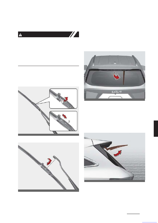
1. Raise the wiper arm.
2. Lift up the wiper blade clip. Then pull

down the blade assembly and remove
it.

3. Install the new blade assembly.

4. Make sure that both blade assemblies 

are installed firmly by trying to pull it 
slightly.

5. Return the wiper arm onto the wind

-

shield.

6. Turn ignition to the ON position and

wiper arms will return to the normal
operating position.

Rear wiper blade replacement

1. Within 20 seconds after the vehicle 

ignition is OFF, move the wiper lever 
to MIST position for over 2 seconds 
until the wiper moves down to the 
bottom middle part.

2. Raise the wiper arm and pull out the 

wiper blade assembly.

3. Lift up the wiper blade, and pull the 

blade to remove it.

ODEEV098016NR

ODEEV098017NR

OMQ4H071117

OMQ4070012

CarManuals2.com

Maintenance

28

7

Wiper blades

4. Install the new blade assembly by 

inserting the center part into the slot 
in the wiper arm until it clicks into 
place.

5. Make sure the blade assembly is

installed firmly by trying to pull it
slightly.

If the replacement is complete, put 
down the wiper arm to place it on the 
rear windshield, and turn the vehicle 
ignition to ON and operate the wipers 
to check the blade is installed cor

-

rectly.

To prevent damage to the wiper arms or
other components, have the wiper blade
replaced by a professional workshop.
Kia recommends to visit an authorized
Kia dealer.

CAUTION

If the wiper arm receives too much force 
while pulling the blade, the center part 
may be damaged.

CAUTION

• The wiper could not operate for 

approx. 10 seconds when the wiper is 
operated without washer fluid or the 
blades are frozen. This is not a mal

-

function, it is a wiper protection sys

-

tem activated by motor overload 
circuit within the wiper motor.

• The front windshield should be cleaned

with water hose and wiped with clean
towel with wiper blades raised up. Also,
the wiper blades should be wiped clean
when the grease or wax is applied to
the blades.

OMQ4070104L

OMQ4070094L

CarManuals2.com

29

7

7

Maintenance

Battery

Battery

For best battery service

• Keep the battery securely mounted.

Keep the battery top clean and dry.

Keep the terminals and connections

clean, tight, and coated with petro

-

leum jelly or terminal grease.

• Rinse any spilled electrolyte from the

battery immediately with a solution of
water and baking soda.

• If the vehicle is not going to be used

for an extended time, disconnect the
battery cables.

NOTICE

Your vehicle is equipped with mainte

-

nance free battery. If your vehicle is 
equipped with the battery marked with 
LOWER and UPPER on the side, you
can check the electrolyte level. The
electro

-

lyte level should be between

LOWER and UPPER. If the electrolyte
level is low, it should be added distilled
(demineral

-

ized) water (Never add

sulfuric acid or other electrolyte). When
refill, be careful not to splash the battery
and adjacent components. And do not
overfill the bat

-

tery cells. It can cause

corrosion on other parts. Make sure that
the cell caps are tightened.

Contact an authorized Kia dealer.

W ARNING

Risk of explosion

Keep lit cigarettes and all other 
flames or sparks away from 
the battery.

The battery contains hydrogen

-- a highly combustible gas 
which will explode if it comes 
in contact with a flame or

spark.

Keep batteries out of the reach 
of children because batteries 
contain highly corrosive SUL

-

FURIC ACID and electrolytes.

Do not allow battery acid to contact your 
skin, eyes, clothing or paint finish.

Wear eye protection when 
charging or working near a
battery. Always provide venti

-

lation when working in an

enclosed space.

Always read the following 
instructions carefully when 
handling a battery.

If any electrolyte gets into
your eyes, flush your eyes with 
clean water for at least 15 min

-

utes and get immediate medi

-

cal attention. If electrolyte gets on your 
skin, thoroughly wash the contacted 
area. If you feel pain or burning sensa

-

tion, get medical attention immediately.

An inappropriately disposed 
battery can be harmful to the 
environment and human 
health. Dispose the battery

according to your local law(s) or regula

-

tion.

OMQ4070025

CarManuals2.com

Maintenance

30

7

Battery

The battery contains lead. Do 
not dispose of it after use.
Please return the battery to an 
authorized Kia dealer to be

recycled.
Never attempt to recharge the battery 
when the battery cables are connected.

W ARNING

Risk of electrocution
Never touch the electrical ignition sys

-

tem while the vehicle is running. This 
system works with high voltage, which 
can "zap" you.

NOTICE

If you connect unauthorized electronic
devices to the battery, the battery may
be discharged. Never use unauthorized
devices.

W ARNING

Recharging battery
Never attempt to recharge the battery 
when the battery cables are connected.

W ARNING

Battery lead compound
Battery posts, terminals, and related 
accessories contain lead and lead com

-

pounds. Wash hands after handling.

Battery recharging

Should your vehicle's battery become 
discharged either run the engine for at 
least 60 minutes driving or at idle. Alter

-

natively you may connect a fully auto

-

matic regulated charger to the engine 
compartment front jumper posts or at the
battery in the liftgate.

When recharging the battery, observe 
the following precautions:
• The battery must be removed from the

vehicle and placed in an area with 
good ventilation.

• Do not allow cigarettes, sparks, or 

flame near the battery.

• Watch the battery during charging, 

and stop or reduce the charging rate 
in following cases:

1. the battery cells begin gassing 

(boiling) violently

2. the electrolyte temperature of any 

cell exceeds 49

°C (120 °F).

• Wear eye protection when checking 

the battery during charging.

• Before performing maintenance or 

recharging the battery, turn off all 
accessories and stop the vehicle.

• Disconnect the battery charger in the 

following order.

1. Turn off the battery charger main 

switch.

2. Unhook the negative clamp from 

the negative battery terminal.

3. Unhook the positive clamp from the 

positive battery terminal.

• The negative battery cable must be 

removed first and installed last when 
the battery is disconnected.

CAUTION

AGM battery
• Absorbent Glass Mat (AGM) batteries 

are maintenance free and have the 
AGM battery serviced by an autho

-

rized Kia dealer.

For charging your AGM battery, use 
only fully automatic battery chargers 
that are specially developed for AGM 
batteries.

CarManuals2.com

31

7

7

Maintenance

Tires and wheels

• When replacing the AGM battery, use

parts for replacement from an autho

-

rized Kia dealer.

• Do not open or remove the cap on top 

of the battery. This may cause leaks 
of internal electrolyte that could result 
in severe injury.

Reset items

The following items should be reset after 
the battery has been discharged or the 
battery has been disconnected.
• Auto up/down window (Refer to "Win

-

dow opening and closing" on page 4-
42)

• Trip computer (Refer to "Trip informa

-

tion (trip computer)" on page 4-88)

• Climate control system (Refer to 

"Automatic climate control system (if 
equipped)" on page 4-146)

• Sunroof (Refer to "Panorama sunroof 

(if equipped)" on page 4-52)

• Driver's seat position (Refer to "Driver 

Position Memory System (if 
equipped)" on page 4-26)

• Trip computer information settings

(Refer to "LCD displays" on page 4-
88)

• Radio presets

Clock

Tires and wheels

For proper maintenance, safety, and 
maximum fuel economy, you must 
always maintain the recommended tire 
pressures and stay within the load limits 
and weight distribution recommended for
your vehicle.

Recommended cold tire inflation 
pressures

All tire pressures should be checked 
when the tires are cold. "Cold Tires" 
means the vehicle has not been driven 
for at least three hours or driven less 
than 1 mile (1.6 km).

Recommended pressures must be main

-

tained for the best ride, vehicle handling,
and minimum tire wear.

For recommended pressure, refer to 
"Tires and wheels" on page 7-31.

All specifications (sizes and pressures) 
can be found on a label attached to the 
driver's side center pillar.

W ARNING

Tire underinflation
Inflate your tires consistent with the 
instructions provided in this manual. 
Regularly check the tire inflation pres

-

sure, and correct it as needed; at least 
twice a month and before any long trips

OMQ4AH080004

CarManuals2.com

Maintenance

32

7

Tires and wheels

on the road. If you fail to observe this 
precaution, you may be driving on 
underinflated tires, which may not only 
compromise your vehicle's driving stabil

-

ity, but may also lead to tire damage and 
the risk of an accident. This risk is much 
higher on hot days and when driving for 
long periods at high speeds.

Failure to maintain specified pressure 
may result in excessive wear, poor han

-

dling, reduced fuel economy, deforma

-

tion of tire and/or wheel, harsh ride 
conditions, possibility for additional 
damage from road hazards, or result in 
tire failure.

Tire pressure

Always observe the following:
• Check tire pressure when the tires are 

cold. (After vehicle has been parked 
for at least three hours or hasn't been 
driven more than 1 mile (1.6 km) since 
startup.)

• Check the pressure of your spare tire 

each time you check the pressure of 
other tires. (if equipped)

• Never overload your vehicle. Be care

-

ful not to overload a vehicle luggage 
rack if your vehicle is equipped with 
one.

• Warm tires normally exceed recom

-

mended cold tire pressures by 28 ~ 41 
kPa (4 ~ 6 psi). Do not release air from 
warm tires to adjust the pressure or the
tires will be underinflated.

W ARNING

Tire Inflation
Overinflation or underinflation can reduce
tire life, adversely affect vehicle handling,
and lead to sudden tire failure.

This could result in loss of vehicle control 
and potential injury.

Checking tire inflation pressure

Check your tires once a month or more. 

Use a good quality gauge to check tire
pressure. You cannot tell if your tires are
properly inflated simply by looking at 
them. Radial tires may look properly 
inflated even when they're underin

-

flated.

Check the tire's inflation pressure when 
the tires are cold. "Cold" means your 
vehicle has been sitting or at least three 
hours or driven no more than 1 mile (1.6 
km).

1. Remove the valve cap from the tire 

valve stem.

2. Press the tire gauge firmly onto the 

valve to get a pressure measurement. 
If the cold tire inflation pressure 
matches the recommended pressure 
on the tire and loading information 
label, no further adjustment is neces

-

sary.

3. If the pressure is low, add air until you 

reach the recommended amount.

4. If you overfill the tire, release air by 

pushing on the metal stem in the cen

-

ter of the tire valve.

5. Recheck the tire pressure with the tire 

gauge.

6. Be sure to put the valve caps back on 

the valve stems. They help prevent 
leaks by keeping out dirt and mois

-

ture.

Inspect your tires frequently for proper 
inflation as well as wear and damage. 
Always use a tire pressure gauge.

Tires with too much or too little pressure
wear unevenly. This could result in poor
handling, loss of vehicle control, and

CarManuals2.com

33

7

7

Maintenance

Tires and wheels

sudden tire failure leading to accidents, 
injuries, and even death. The recom

-

mended cold tire pressure for your vehi

-

cle can be found in this manual and on 
the tire label located on the driver's side 
center pillar.

Tire rotation

To equalize tread wear, it is recom

-

mended that the tires be rotated every 
13,000 km (8,000 miles) or sooner if 
irregular wear develops.

During rotation, check the tires for cor

-

rect balance.

When rotating tires, check for uneven 
wear and damage. Abnormal wear is 
usually caused by incorrect tire pres

-

sure, improper wheel alignment, out of-
balance wheels, severe braking or 
severe cornering. Look for bumps or 
bulges in the tread or side of tire.
Replace the tire if you find either of
these conditions. Replace the tire if fab

-

ric or cord is visible. After rotation, be
sure to bring the front and rear tire pres

-

sures to specification and check lug nut 
tightness. (proper torque is 79 ~ 94 lbf·ft 
[79 ~ 94 lbf·ft])

Refer to "Tires and wheels" on page 7-31.
Disc brake pads should be inspected for
wear whenever tires are rotated.

With a full-size spare tire (if equipped)

Without a spare tire

Directional tires (if equipped)

Rotate radial tires that have an asym

-

metric tread pattern only from front to 
rear and not from right to left.

W ARNING

Mixing tires
Do not mix bias ply and radial ply tires 
under any circumstances. This may
cause unusual handling characteristics.

Wheel alignment and tire balance

The wheels on your vehicle were aligned 
and balanced carefully at the factory to 
give you the longest tire life and best 
overall performance.

If you notice unusual tire wear or your 
vehicle pulling one way or the other, the 
alignment may need to be reset.

If you notice your vehicle vibrating when 
driving on a smooth road, your wheels 
may need to be rebalanced.

CAUTION

Wheel weight
Improper wheel weights can damage
your vehicle's aluminum wheels. Use
only approved wheel weights.

CBGQ0706

ODEEV098029NR

CBGQ0707A

CarManuals2.com

Maintenance

34

7

Tires and wheels

Tire replacement

If the tire is worn evenly, a tread wear 
indicator will appear as a solid band 
across the tread.

[A] : Tread wear indicator
This shows there is less than 1/16 in (1.6 
mm) of tread left on the tire. Replace the 
tire when this happens.

Do not wait for the band to appear 
across the entire tread before replacing 
the tire.

The Anti-lock Brake System (ABS)
works by comparing the speed of the
wheels. The tire size affects wheel
speed. When replacing tires, all 4 tires 
must use the same size originally
supplied with the vehicle. Using tires of a
different size can cause the ABS and
Electronic Stability Control (ESC) to
work irregularly.

It is best to replace all four tires at the 
same time. If that is not possible, or nec

-

essary, then replace the two front or two 
rear tires as a pair. Replacing just one tire
can seriously affect your vehicle's 
handling.

NOTICE

When replacing tires, we recommend to 
use the same type of tires originally sup

-

plied with the vehicles to avoid impact

-

ing driving performance.

Wheel replacement

When replacing the metal wheels for any 
reason, make sure the new wheels are 
equivalent to the original factory units in 
diameter, rim width and offset.

A wheel with an incorrect size may 
adversely affect many things: wheel and 
bearing life, braking and stopping abili

-

ties, handling characteristics, ground 
clearance, body-to-tire clearance, snow 
chain clearance, speedometer and 
odometer calibration, headlamp aiming 
and bumper height.

CAUTION

Wheels
Wheels that do not meet Kia specifica

-

tions may fit poorly and result in dam

-

age to the vehicle or unusual handling
and poor vehicle control.

Tire traction

Tire traction can be reduced if you drive 
on worn tires, tires that are improperly 
inflated or on slippery road surfaces.

Tires should be replaced when tread 
wear indicators appear. Slow down 
whenever there is rain, snow or ice on 
the road to reduce the possibility of los

-

ing control of the vehicle.

Tire maintenance

In addition to proper inflation, correct 
wheel alignment helps to decrease tire 
wear.

If you find a tire is worn unevenly, have
your dealer check the wheel alignment.
Make sure the newly installed tires are
balanced correctly to increase vehicle
ride comfort and tire life. In addition,

OMQ4070103L

CarManuals2.com

35

7

7

Maintenance

Tires and wheels

always rebalance the tire when the tire is 
removed from the wheel.

Tire sidewall labeling

This information identifies and describes 
the fundamental characteristics of the tire
and also provides the Tire Identifica

-

tion

Number (TIN) for safety standard 
certification.

The TIN can be used to identify the tire 
in case of a recall.

1. Manufacturer or brand name

Manufacturer or Brand name is shown.

2. Tire size designation

A tire's sidewall is marked with a tire size 
designation. You will need this informa

-

tion when selecting replacement tires for 
your vehicle. The following explains what
the letters and numbers in the tire size
designation mean.
Example tire size designation: 

(These numbers are provided as an
example only; your tire size designator 
could vary depending on your vehicle.)

P255/45R20 105V
• P: Applicable vehicle type (tires 

marked with the prefix "P" are 
intended for use on passenger vehi

-

cles or light trucks; however, not all 
tires have this marking).

• 255: Tire width in millimeters.
• 45: Aspect ratio. The tire's section 

height as a percentage of its width.

• R: Tire construction code (Radial).

20: Rim diameter in inches.

• 105: Load Index, a numerical code

associated with the maximum load
the tire can carry.

• V: Speed Rating Symbol. See the 

speed rating chart in this section for 
additional information.

Wheel size designation

Wheels are also marked with important 
information that you need if you ever 
have to replace one. The following 
explains what the letters and numbers in 
the wheel size designation mean.

Example wheel size designation:

8.5JX20
• 8.5: Rim width in inches.
• J: Rim contour designation.

20: Rim diameter in inches.

Tire speed ratings

The chart below lists many of the differ

-

ent speed ratings currently being used 
for passenger vehicle tires. The speed 
rating is part of the tire size designation 
on the sidewall of the tire. This symbol 
corresponds to that tire's designed max

-

imum safe operating speed.

ODEEV098031NR

CarManuals2.com

Speed Rating

Symbol

Maximum Speed

S

180 km/h (112 mph)

T

190 km/h (118 mph)

H

210 km/h (130 mph)

V

240 km/h (149 mph)

Maintenance

4. Tire ply composition and mate

-

rial

The number of layers or plies of rubber-
coated fabric in the tire. Tire manufac

-

turers also must indicate the materials in 
the tire, which include steel, nylon, poly

-

ester, and others. The letter "R" means

7

36

Tires and wheels

3. Checking tire life

Any tires that are over 6 years old, based 
on the manufacturing date, should be 
replaced by new ones. You can find the 
manufacturing date on the tire sidewall 
(possibly on the inside of the wheel), dis

-

playing the DOT code. The DOT code is
a series of numbers on a tire consisting of
numbers and English letters. The 
manufacturing date is designated by the 
last four digits (characters) of the DOT 
code.

DOT: X X X X X X X X OOOO
The front part of the DOT means a plant
code number, tire size and tread pattern
and the last four numbers indicate week
and year manufactured.

For example:
DOT XXXX XXXX 1623 represents
that the tire was produced in the 16th
week of 2023.

W ARNING

Tire age
Replace tires within the recommended 
time frame. Failure to replace tires as 
recommended can result in sudden tire 
failure, which could lead to a loss of con

-

trol and an accident.

radial ply construction; the letter "D" 
means diagonal or bias ply construction; 
and the letter "B" means belted-bias ply 
construction.

CarManuals2.com

5. Maximum permissible inflation 
pressure

This number is the greatest amount of air
pressure that should be put in the tire.
Do not exceed the maximum per

-

missible inflation pressure. Refer to "Cer

-

tification label" on page 5-200 for 
recommended inflation pressure.

6. Maximum load rating

This number indicates the maximum load
in kilograms and pounds that can be
carried by the tire. When replacing the
tires on the vehicle, always use a tire that
has the same load rating as the fac

-

tory

installed tire.

7. Uniform Tire Quality Grading

Quality grades can be found where 
applicable on the tire sidewall between 
tread shoulder and maximum section 
width.

For example:
• Treadwear 200

Traction AA

• Temperature A
Tires degrade over time, even when they 
are not being used. Regardless of the 
remaining tread, we recommend that tires 
be replaced after approximately six
(6) years of normal service. Heat caused
by hot climate or frequent high loading 
conditions can accelerate the aging pro

-

cess.

Speed Rating

Symbol

Maximum Speed

W

270 km/h (168 mph)

Y

300 km/h (186 mph)

37

7

7

Maintenance

Tires and wheels

Tread wear

The tread wear grade is a comparative 
rating based on the wear rate of the tire 
when tested under controlled conditions 
on a specified government test course. 
For example, a tire graded 150 would 
wear one-and-a-half times (1½) as well 
on the government course as a tire 
graded 100.

The relative performance of tires 
depends upon the actual conditions of 
their use. Performance may depart sig

-

nificantly from the norm due to varia

-

tions in driving habits, service practices 
and differences in road characteristics 
and climate.

These grades are molded on the side-
walls of passenger vehicle tires. The tires 
available as standard or optional equip

-

ment on your vehicle may vary with 
respect to grade.

CarManuals2.com

Traction - AA, A, B & C

The traction grades, from highest to low

-

est, are AA, A, B and C. Those grades 
represent the tire's ability to stop on wet 
pavement as measured under controlled 
conditions on specified government test 
surfaces of asphalt and concrete. A tire 
marked C may have poor traction per

-

formance.

The traction grade assigned to this tire is 
based on straight-ahead braking trac

-

tion tests, and does not include accelera

-

tion, cornering, hydroplaning, or peak 
traction characteristics.

Temperature -A & B

The temperature grades are A (the high

-

est) and B representing the tire's resis

-

tance to the generation of heat and its 
ability to dissipate heat when tested

under controlled conditions on a speci

-

fied indoor laboratory test wheel.

+Grades B and A represent higher levels 
of performance on the laboratory test 
wheel than the minimum required by law.

Tire terminology and definitions

Refer to the following for detailed defini

-

tions of the terms that are found in the tire 
description.

Air Pressure The amount of air inside 
the tire pressing outward on the tire. Air 
pressure is expressed in pounds per 
square inch (psi) or kilopascal (kPa).

Accessory Weight The combined 
weight of optional accessories. Some 
examples of optional accessories are 
automatic transmission, power seats, 
and air conditioning.

Aspect Ratio The relationship of a tire's 
height to its width.

Belt A rubber coated layer of cords that 
is located between the plies and the 
tread. Cords may be made from steel or 
other reinforcing materials.

Bead The tire bead contains steel wires 
wrapped by steel cords that hold the tire 
onto the rim.

Bias Ply Tire A pneumatic tire in which 
the plies are laid at alternate angles less 
than 90 degrees to the centerline of the 
tread.

Cold Tire Pressure The amount of air 
pressure in a tire, measured in pounds 
per square inch (psi) or kilopascals (kPa) 
before a tire has built up heat from driv

-

ing.

Curb Weight The weight of a motor 
vehicle with standard and optional 
equipment (including the maximum 
capacity of fuel, oil and coolant), but 
without passengers and cargo.

Maintenance

38

CarManuals2.com

7

Tires and wheels

DOT Markings The DOT code includes 
the Tire Identification Number (TIN), an 
alphanumeric designator which can also 
identify the tire manufacturer, produc

-

tion

plant, brand and date of production.

GVW R Gross Vehicle Weight Rating 
GAW R FRT Gross Axle Weight
Rating for the Front axle.

GAW R RR Gross Axle Weight Rating
for the Rear axle.

Intended Outboard Sidewall The side of 
an asymmetrical tire that must always 
face outward when mounted on a vehi

-

cle.

Kilopascal (kPa) The metric unit for air 
pressure.

Light truck (LT) tire A tire designated by
its manufacturer as primarily intended for
use on lightweight trucks or multipurpose
passenger vehicles.

Load ratings The maximum load that a
tire is rated to carry for a given inflation
pressure.

Load Index An assigned number rang

-

ing from 1 to 279 that corresponds to the 
load carrying capacity of a tire.

Maximum Inflation Pressure The maxi

-

mum air pressure to which a cold tire 
may be inflated. The maximum air pres

-

sure is molded onto the sidewall.

Maximum Load Rating The load rating 
for a tire at the maximum permissible 
inflation pressure for that tire.

Maximum Loaded Vehicle Weight The 
sum of curb weight; accessory weight; 
vehicle capacity weight; and production 
options weight.

Normal Occupant Weight The number 
of occupants a vehicle is designed to 
seat multiplied by 68 kg (150 lbs.).

Occupant Distribution Designated 
seating positions.

Outward Facing Sidewall The side of a
asymmetrical tire that has a particular 
side that faces outward when mounted 
on a vehicle. The outward facing side

-

wall bears white lettering or bears man

-

ufacturer, brand, and/or model name 
molding that is higher or deeper than the
same moldings on the inner facing 
sidewall.

Passenger (P-Metric) Tire A tire used
on passenger cars and some light duty
trucks and multipurpose vehicles.

Ply A layer of rubber-coated parallel 
cords.

Pneumatic tire A mechanical device 
made of rubber, chemicals, fabric and 
steel or other materials, that, when 
mounted on an automotive wheel, pro

-

vides the traction and contains the gas 
or fluid that sustains the load.

Production options weight The com

-

bined weight of installed regular produc

-

tion options weighing over 2.3 kg (5 lbs.) 
in excess of the standard items which 
they replace, not previously considered in
curb weight or accessory weight.
Examples include heavy duty brakes, 
ride levelers, roof rack, heavy duty bat

-

tery, and special trim.

Recommended Inflation Pressure
Vehicle manufacturer's recommended 
tire inflation pressure and shown on the 
tire placard.

Radial Ply Tire A pneumatic tire in which
the ply cords that extend to the beads
are laid at 90 degrees to the cen

-

terline 

of the tread.

Rim A metal support for a tire and upon 
which the tire beads are seated.

Sidewall The portion of a tire between 
the tread and the bead.

39

use all year round, including snowy and 
icy road conditions.

All season tires are identified by ALL 
SEASON and/or M+S (Mud and Snow) 
on the tire sidewall. Snow tires have bet

-

ter snow traction than all season tires and
may be more appropriate in some areas.

Summer tires

Kia specifies summer tires on some 
models to provide superior performance 
on dry roads.

Summer tire performance is substan

-

tially reduced in snow and ice. Summer 
tires do not have the tire traction rating 
M+S (Mud and Snow) on the tire side 
wall. if you plan to operate your vehicle 
in snowy or icy conditions, Kia recom

-

mends the use of snow tires or all sea

-

son tires on all four wheels.

Snow tires

If you equip your vehicle with snow tires, 
they should be the same size and have 
the same load capacity as the original 
tires.

Snow tires should be installed on all four

7

wheels; otherwise, poor handling may 
result.

Snow tires should carry 28 kPa (4 
psi)more air pressure than the pressure 
recommended for the standard tires on 
the tire label on the driver's side of the 
center pillar, or up to the maximum 
pressure shown on the tire sidewall, 
whichever is less.

Do not drive faster than 120 km/h (75 
mph) when your vehicle is equipped 
with snow tires.

7

Maintenance

Tires and wheels

Speed Rating An alphanumeric code 
assigned to a tire indicating the maxi

-

mum speed at which a tire can operate.

Traction The friction between the tire 
and the road surface. The amount of 
grip provided.

Tread The portion of a tire that comes 
into contact with the road.

Treadwear Indicators Narrow bands, 
sometimes called "wear bars," that show 
across the tread of a tire when only 1.6 
mm (2/32 inch) of tread remains.

UTQGS Uniform Tire Quality Grading 
Standards, a tire information system that 
provides consumers with ratings for a
tire's traction, temperature and tread

-

wear. Ratings are determined by tire 
manufacturers using government test

-

ing procedures. The ratings are molded 
into the sidewall of the tire.

Vehicle Capacity Weight The weight of 
designated seating positions multiplied 
by 68 kg (150 lbs.) plus the rated cargo 
and luggage load.

Vehicle Maximum Load on the Tire
Load on an individual tire due to curb
and accessory weight plus maximum
occupant and cargo weight.

Vehicle Normal Load on the Tire Load 
on an individual tire that is determined by
distributing to each axle its share of the
curb weight, accessory weight, and 
normal occupant weight and driving by 
2.

Vehicle Placard A label permanently 
attached to a vehicle showing the origi

-

nal equipment tire size and recom

-

mended inflation pressure.

All season tires

Kia specifies all season tires on some 
models to provide good performance for

W ARNING

CarManuals2.com

Do not use summer tires at tempera

-

tures below 7

°C (45 °F) or when driving

Maintenance

40

7

Tires and wheels

on snow or ice. At temperatures below 7
°C (45 °F), summer tires can lose elastic

-

ity, and therefore traction and braking
power as well. Change the tires on your 
vehicle to winter or all-weather tires of the
same size as the standard tires of the
vehicle. Both types of tires are identi

-

fied

by the M+S (Mud and Snow) mark

-

ing.

Using summer tires at very cold 
temperatures could cause cracks to
form, thereby damaging the tires per

-

manently.

Radial-ply tires

Radial-ply tires provide improved tread 
life, road hazard resistance and 
smoother high speed ride.

The radial-ply tires used on this vehicle 
are of belted construction, and are 
selected to complement the ride and 
handling characteristics of your vehicle. 
Radial-ply tires have the same load car

-

rying capacity, as bias-ply or bias belted 
tires of the same size, and use the same 
recommended inflation pressure.

Mixing of radial-ply tires with bias-ply or 
bias belted tires is not recommended. 
Any combinations of radial-ply and bias-
ply or bias belted tires when used on the 
same vehicle will seriously deteriorate 
vehicle handling. The best rule to follow 
is: Identical radial-ply tires should always 
be used as a set of four.

Longer wearing tires can be more sus

-

ceptible to irregular tread wear. It is very 
important to follow the tire rotation interval
shown in this section to achieve the tread
life potential of these tires.
Cuts and punctures in radial-ply tires are
repairable only in the tread area, 
because of sidewall flexing. Consult your 
tire dealer for radial-ply tire repairs.

Low aspect ratio tires (if
equipped)

Low aspect ratio tires, whose aspect 
ratio is lower than 50, are provided for 
sporty looks.

Because the low aspect ratio tires are
optimized for handling and braking, it
may be more uncomfortable to ride in
and there is more noise compare with
normal tires.

CAUTION

CarManuals2.com

Because the sidewall of the low aspect 
ratio tire is shorter than the normal, the 
wheel and tire of the low aspect ratio tire 
is easier to be damaged. So, follow the 
instructions below.
• When driving on a rough road or off 

road, drive cautiously because tires 
and wheels may be damaged. And 
after driving, inspect tires and wheels.

• When passing over a pothole, speed 

bump, manhole, or curb stone, drive 
slowly so that the tires and wheels are 
not damaged.

• If the tire is impacted, we recommend 

that you inspect the tire condition or 
contact an authorized Kia dealer.

• To prevent damage to the tire, inspect 

the tire condition and pressure every 
3,000 km (1,900 miles).

• It is not easy to recognize the tire 

damage with your own eyes. But if 
there is the slightest hint of tire dam

-

age, even though you cannot see the 
tire damage with your own eyes, have 
the tire checked or replaced because 
the tire damage may cause air leak

-

age from the tire.

• If the tire is damaged by driving on a

rough road, off road, pothole, man

-

hole, or curb stone, it will not be cov

-

ered by the warranty.

41

7

7

Maintenance

Fuses

• You can find out the tire information 

on the tire sidewall.

Fuses

Blade type

Cartridge type

Multi fuse

High voltage fuse

* Left side: Normal, Right side: Blown
* The actual fuse/relay panel label may 

differ from equipped items.

A vehicle's electrical system is protected 
from electrical overload damage by 
fuses.

This vehicle has 2 (or 3) fuse panels, one 
located in the driver's side panel bolster,

ODEEV098032NR

ODEEV098077NR

ODEEV098078NR

OMQ4070071L

CarManuals2.com

Maintenance

42

7

Fuses

the other in the engine compartment 
near the battery.

If any of your vehicle's lights, accesso

-

ries, or controls do not work, check the 
appropriate circuit fuse. If a fuse has 
blown, the element inside the fuse will 
melt.

If the electrical system does not work, 
first check the driver's side fuse panel.

If the replacement fuse blows, this indi

-

cates an electrical problem. Avoid using 
the system involved and immediately 
consult an authorized Kia dealer.

Three kinds of fuses are used: blade
type for lower amperage rating, car

-

tridge type, and multi fuse for higher
amperage ratings.

W ARNING

Fuse replacement
• Never replace a fuse with anything 

but another fuse of the same rating.

• A higher capacity fuse could cause 

damage and possibly a fire.

• Never install a wire or aluminum foil 

instead of the proper fuse - even as a
temporary repair. It may cause exten

-

sive wiring damage and a possible 
fire.

• Do not arbitrarily modify or add-on 

electric wiring to the vehicle.

CAUTION

Do not use a screwdriver or any other 
metal object to remove fuses because it 
may cause a short circuit and damage 
the system.

NOTICE

• When replacing a fuse, turn the igni

-

tion 'OFF' and turn off switches of all

electrical devices then remove battery 
(-) terminal.

• The actual fuse/relay panel label may 

differ from equipped items.

W ARNING

Electrical fire
Always ensure replacements fuses and 
relays are securely fastened when 
installed. Failure to do so can result in a
vehicle fire.

Do not remove fuses, relays and termi

-

nals fastened with bolts or nuts. The 
fuses, relays and terminals may be fas

-

tened incompletely, and it may cause a
possible fire. If fuses, relays and termi

-

nals fastened with bolts or nuts are 
blown, consult with an authorized Kia 
dealer.

CAUTION

When replacing a blown fuse or relay, 
make sure the new fuse or relay fits 
tightly into the clips. Failure to tightly 
install the fuse or relay may cause dam

-

age to the wiring and electric systems.

CAUTION

CarManuals2.com

• Do not input any other objects except 

fuses or relays into fuse/relay termi

-

nals such as a screwdriver or wiring. It 
may cause contact failure and system 
malfunction.

• Do not plug in screwdrivers or after

-

market wiring into the terminal origi

-

nally designed for fuse and relays only.
The electrical system and wiring of the
vehicle interior may be dam

-

aged or

burned due to contact failure.

• If you directly connect the wire on the 

taillamp or replace the bulb which is

43

7

7

Maintenance

Fuses

over the regulated capacity to install 
trailers etc., the inner junction block 
can get burned.

W ARNING

Electrical wiring repairs
All electrical repairs should be per

-

formed by authorized Kia dealerships 
using approved Kia parts. Using other 
wiring components, especially when ret

-

rofitting multimedia or theft alarm sys

-

tem, car phone or radio may cause 
vehicle damage and increase the risk of 
a vehicle fire.

NOTICE

Remodeling prohibited
Do not rewire your vehicle in any way as 
doing so may affect the performance of 
several safety features in your vehicle. 
Rewiring your vehicle may also void your 
warranty and cause you to be responsi

-

ble for any subsequent vehicle damage 
which may result.

Inner panel fuse replacement

1. Turn the ignition switch or ENGINE 

START/STOP button and all other 
switches off.

2. Open the fuse panel cover.

3. Pull the suspected fuse straight out. 

Use the removal tool provided in the 
main fuse box in the engine compart

-

ment.

4. Check the removed fuse; replace it if 

it is blown.

Spare fuses are provided in the instru

-

ment panel fuse panel (or in the engine
compartment fuse panel).

5. Push in a new fuse of the same rating, 

and make sure it fits tightly in the 
clips.

If it fits loosely, consult an authorized Kia 
dealer.

If you do not have a spare, use a fuse of 
the same rating from a circuit you may 
not need for operating the vehicle, such 
as the cigarette lighter fuse.

If the headlamps or taillamps, stoplights, 
courtesy lamp, day time running lights 
(DRL) do not work and the fuses are OK, 
consult an authorized Kia dealer.

Engine compartment fuse 
replacement

1. Turn the ignition and all other 

switches off.

2. Remove the fuse panel cover by 

pressing the tab and pulling the cover 
up.

OMQ4A071013

OMQ4070027L

CarManuals2.com

Maintenance

44

7

Fuses

3. Check the removed fuse; replace it if 

it is blown. To remove or insert the 
fuse, use the fuse puller in the engine 
compartment fuse panel.

4. Push in a new fuse of the same rating, 

and make sure it fits tightly in the
clips. If it fits loosely, consult an autho

-

rized Kia dealer.

CAUTION

After checking the fuse panel in the 
engine compartment, securely install the 
fuse panel cover through the audible 
clicking sound.

If not, electrical failures may occur from 
water contact.

NOTICE

If the multi fuse is blown, consult an 
authorized Kia dealer.

NOTICE

The electronic system may not function 
correctly even when the engine room and
internal fuse box's individual fuses are not
disconnected. In such case the cause of
the problem may be disconnec

-

tion of the

main fuse (BFT type), which is located 
inside the positive battery termi

-

nal (+)

cap. Since the main fuse is

designed more intricately than other
parts, visit the nearest authorized Kia
dealer.

Main fuse (Multi fuse)

If the main fuse is blown, it must be 
removed as follows:

1. Turn off the engine.

2. Disconnect the negative battery cable.
3. Remove the nuts shown in the picture 

above.

4. Replace the fuse with a new one of 

the same rating.

5. Reinstall in the reverse order of 

removal.

CAUTION

Visually inspect the battery cap for 
secure closing. If the battery cap is not 
securely latched, the electrical system 
may be damaged to due influx of mois

-

ture into the system.

Fuse/relay panel description

Inside the fuse/relay panel covers, you
can find the fuse/relay label describing
fuse/relay name and capacity.

OMQ4070027

OMQ4070028

CarManuals2.com

45

7

7

Maintenance

Fuses

NOTICE

Not all fuse panel descriptions in this 
manual may be applicable to your vehi

-

cle. It is accurate at the time of printing. 
When you inspect the fuse panel in your 
vehicle, refer to the fuse panel label.

Driver's side fuse panel

OMQ4A071083

OMQ4A070102

CarManuals2.com

Maintenance

46

7

Fuses

ICU Junction Block

Fuse Name

Fuse rating

Circuit Protected

25A

AMP (Amplifier)

30A

Low DC (Direct Current)-DC (Direct Current) Converter

30A

Driver Power Seat Switch, IMS (Integrated memory sys

-

tem) Control Module

25A

Rear Power Window Switch LH, Rear Safety Power 
Win

-

dow Module LH, Driver Safety Power Window

Module, Driver Power Window Switch

30A

Passenger Power Seat Switch

20A

SEAT_AST Air Ventilation Seat Warmer, SEAT_AST
Seat Warmer, Data Link Connector

15A

2nd Seat Warmer LH Control Module

20A

2nd Seat RH Folding Actuator

25A

Rear Power Window Switch RH, Rear Safety Power
Win

-

dow Module RH, Passenger Power Window Switch,

Pas

-

senger Safety Power Window Module

15A

Tail Gate Relay

20A

2nd Seat LH Folding Actuator

20A

Door Lock/Unlock Relay, Dead Lock Relay

10A

Rear A/C Control Module

25A

Low DC (Direct Current)-DC (Direct Current) Converter

15A

2nd Seat Warmer RH Control Module

10A

Head-Up Display, Rear A/C Control Module, Front A/C 
Control Module, Front A/C Control Panel, Low DC (Direct 
Current) -DC (Direct Current) Converter, Surround View 
Monitor Unit

10A

Ignition Switch

10A

Luggage USB Charge Connector LH/RH

15A

Rear Console USB Charge Connector LH/RH,
USB_

-

SEAT_DRV, USB_SEAT_AST

CarManuals2.com

47

7

7

Maintenance

Fuses

Fuse Name

Fuse rating

Circuit Protected

7.5A

IBU (Integrated Body Control Unit), ADAS Unit, Front 
View Camera, Crash Pad Switch, Surround View Monitor 
Unit, 4WD ECU, Front Console Switch, Rear Corner 
Radar LH/RH

15A

SRS (Supplemental Restraint System) Control
Module, Passenger Occupant Detection Sensor

15A

Multifunction Switch

10A

ADAS Unit, Surround View Monitor Unit, IBU (Integrated
Body Control Unit), Front USB Charge Connector LH/RH,
Low DC (Direct Current) - DC (Direct Current) Converter

10A

Key Solenoid, Driver/Passenger Smart Key Outside Han

-

dle, Driver Door Area Unit, Driver/Passenger Power Out

-

side Mirror, Power Tailgate Unit, ROA, Driver Air 
Ventilation Seat Control Module, Driver Seat Warmer 
Control Module

7.5A

IBU (Integrated Body Control Unit)

7.5A

Driver Door Area Unit, ATM (Automatic Transmission) 
Shift Lever

15A

Rear A/C Blower Motor, ICU Junction Block (Fuse -
Rear A/C Control Module)

7.5A

Instrument Cluster, Overhead Console

7.5A

ADAS Unit, Rear Console AC Inverter Outlet, AC
Inverter, 2nd Seat Warmer LH/RH Control Module, Rear
A/C Con

-

trol Module, SEAT_AST Air

Ventilation/SEAT_AST Seat Warmer Control Module

15A

IBU (Integrated Body Control Unit), RAIN SNSR

10A

Stop Lamp Switch

10A

AMP (Amplifier), Front Wireless Charger Unit, Low DC 
(Direct Current) - DC (Direct Current) Converter

7.5A

Front A/C Control Module, Front A/C Control Panel, E/R
Junction Block (PTC (Positive Temperature Coefficient)
Heater #1 Relay, Blower Relay)

10A

SRS (Supplemental Restraint System) Control Module

7.5A

Instrument Cluster, Head-Up Display

10A

Audio, Data Link Connector, Front A/C Control Panel, 
Front A/C Control Module, Crash Pad Switch, Electro 
Chromic Mirror, 1st Air Ventilation Seat Control Module, 
2nd Seat Warmer LH/RH Control Module

CarManuals2.com

Maintenance

48

7

Fuses

Engine compartment fuse panel

Fuse Name

Fuse rating

Circuit Protected

7.5A

IBU (Integrated Body Control Unit)

10A

Surround View Monitor Unit, Instrument Cluster, ADAS 
Unit, Front A/C Control Panel, Front A/C Control Module, 
Front Wireless Charger Unit, Head-Up Display

7.5A

IBU (Integrated Body Control Unit), Stop Lamp Switch

7.5A

MDPS (Motor Driven Power Steering) Unit

*MDPS is the same as EPS (Electric Power Steering).

OMQ4070040L

CarManuals2.com

49

7

7

Maintenance

Fuses

Engine Room Junction Block

OMQ4A071028N

Fuse Name

Fuse rating

Circuit Protected

MULTI 

FUSE-
1

80A

Cooling Fan Motor

60A

TCM (Transmission Control Module)

50A

E/R Junction Block (PTC (Positive
Temperature Coefficient) Heater #1 Relay)

50A

ICU Junction Block (IPS)

50A

E/R Junction Block (E-CVVT (Electric -
Continu

-

ously variable valve timing) Relay)

40A

Electronic Oil Pump

40A

ESC (Electronic Stability Control) Control Module

30A

ESC (Electronic Stability Control) Control Module

CarManuals2.com

Maintenance

50

7

Fuses

Fuse Name

Fuse rating

Circuit Protected

MULTI 

FUSE-
2

100A

MDPS (Motor Driven Power Steering) Unit
*MDPS is the same as EPS (Electric Power

Steer

-

ing).

60A

Cooling Fan Motor

60A

PCB Junction Block (Start Relay, IG2 Relay,
IG1 Relay, ACC Relay)

60A

Electronic Oil Pump

50A

ICU Junction Block (Fuse - P/SEAT (DRV),
P/WIN

-

DOW (LH), P/SEAT (PASS), S/HEATER

(REAR LH), 2nd ROW SEAT FOLDING (RH))

40A

E/R Junction Block, (Rear Heated Relay)

40A

Power Tailgate Unit

40A

Sunroof Motor (Glass)

CarManuals2.com

51

7

7

Maintenance

Fuses

PCB Block

Fuse Name

Fuse rating

Circuit Protected

FUSE

60A

ESC (Electronic Stability Control), Control Module

50A

ICU Junction Block (IPS)

20A

[Smartstream 2.5 T-GDi] E/R Junction Block
(Vac

-

uum Pump Relay

20A

E/R Junction Block (Fuel Pump Relay)

15A

PCB Junction Block (Child Lock/Unlock Relay)

50A

E/R Junction Block (Blower Relay)

50A

ICU Junction Block (Fuse - AMP, LDC,
S/HEATER (REAR RH), P/WINDOW (RH), 2nd
ROW SEAT FOLDING (LH))

30A

Trailer Module

30A

AC Inverter

40A

ICU Junction Block (Long Term Load Latch 
Relay, Fuse - TAILGATE OPEN, DOOR LOCK,
S/HEATER

(REAR RH), START,

9

MODULE,

2

IBU,

2A/BAG, BRAKE SWITCH)

20A

4WD ECU

15A

PCM (Power train Control Module)

10A

Battery Sensor

10A

ESC (Electronic Stability Control), Control Module

20A

PCM (Power train Control Module)

10A

Front A/C Control Panel, Front A/C Control Mod

-

ule, Driver/Passenger Power Outside Mirror

10A

Front A/C Control Module

20A

PCM (Power train Control Module)

Fuse Name

Fuse rating

Circuit Protected

40A

E/R Junction Block (Start Relay), PCB Junction
Block (IG2 Relay)

40A

PCB Junction Block (IG1 Relay, ACC Relay)

7.5A

IBU (Integrated Body Control Unit)

20A

Ignition Coil #1/#2/#3/#4

CarManuals2.com

Maintenance

52

7

Fuses

Relay

Refer to the following table for the relay type.

Fuse Name

Fuse rating

Circuit Protected

10A

Electronic Oil Pump

10A

PCM (Power train Control Module)

10A

E/R Junction Block (Fuel Pump Relay)

20A

PCM (Power train Control Module)

15A

Oxygen Sensor (Up/Down)

30A

Front Wiper Motor, Front Wiper (Low) Relay

15A

Rear Wiper Relay, Rear Wiper Motor

15A

Horn Relay

10A

A/Con Relay

15A

B/A Horn Relay

10A

TCM (Transmission Control Module)

10A

Purge Control Solenoid Valve, PCM (Power train Con

-

trol Module), Cooling Fan Motor, Oil Control Valve 
(Exhaust), Variable Oil Pump Solenoid Valve, Canister 
Close Valve, A/Con Relay, [Smartstream 2.5 GDi]
Variable Intake Solenoid Valve
[Smartstream 2.5 T-GDi] RCV (Recirculation
Valve Control) Control Solenoid Valve

15A

Injector #1/#2/#3/#4

15A

PCM (Power train Control Module)

7.5A

ESC (Electronic Stability Control) Control Module

20A

Rear Console Power Outlet

20A

Luggage Power Outlet

Symbol

Relay Name

TYPE

[Smartstream 2.5 T-GDi] Vacuum Pump Relay

MICRO

Start Relay

MICRO

Fuel Pump Relay

MICRO

E-CVVT (Electric - Continuously variable valve timing) Relay

MICRO

PTC (Positive Temperature Coefficient) Heater #1 Relay

MICRO

CarManuals2.com

53

7

7

Maintenance

Fuses

Engine compartment fuse panel 
(Battery terminal cover)

Symbol

Relay Name

TYPE

B/Alarm Horn Relay

MICRO

Blower Relay

MICRO

Rear Heated Relay

MINI

OMQ4070080L

CarManuals2.com

Maintenance

54

7

Fuses

OMQ4070081L

CarManuals2.com

55

7

7

Maintenance

Light bulbs

Light bulbs

Light bulbs are installed in various parts 
of the vehicle to provide lighting inside 
and outside the vehicle as well as to alert 
other vehicles.

Bulb replacement precaution

Please keep extra bulbs on hand with
appropriate wattage ratings in case of
emergencies.

Refer to "Bulb wattage" on page 8-5. 
When changing lamps, first turn off the 
vehicle at a safe place, firmly apply the
parking brake and detach the battery's 
negative (-) terminal.

W ARNING

Working on the lights
Prior to working on the light, firmly apply 
the parking brake, ensure that turn the 
ignition switch or ENGINE START/STOP 
button and turn off the lights to avoid 
sudden movement of the vehicle and 
burning your fingers or receiving an 
electric shock.

Use only bulbs of the specified wattage.

CAUTION

Light replacement
Be sure to replace the burned-out bulb 
with one of the same wattage rating. 
Otherwise, it may cause damage to the 
fuse or electric wiring system.

Fully install light bulbs and any parts 
used to secure them. Failure to do so 
may result in heat damage, fire, or water 
entering the headlamp unit. This may 
damage the headlamps or cause con

-

densation to build up on the lens. To 
prevent damage or fire, make sure bulbs 
are fully seated and locked.

CAUTION

Headlamp lens
To prevent damage, do not clean the 
headlamp lens with chemical solvents or 
strong detergents.

NOTICE

• If the light bulb or lamp connector is 

removed while the lamp is still on, the 
fuse box's electronic system may log
it as a malfunction. Therefore, a lamp 
malfunction incident may be recorded 
as a Diagnostic Trouble Code (DTC)
in the fuse box.

• It is normal for an operating lamp to

flicker momentarily. This is due to a
stabilization function of the vehicle's
electronic control device. If the lamp
lights up normally after momentarily
blinking, then it is functioning as nor

-

mal.

However, if the lamp continues to 
flicker several times or turns off com

-

pletely, there may be an error in the 
vehicle's electronic control device.
Please have the vehicle checked by
an authorized Kia dealer immediately.

NOTICE

Have the headlamp aiming adjusted by 
an authorized Kia dealer after an acci

-

dent or after the headlamp assembly is 
reinstalled.

NOTICE

CarManuals2.com

You can find moisture inside the lens of 
lamps after a car wash or driving in the 
rain. It is a natural event caused by the 
temperature difference between the 
inside and the outside of the lamp and 
does not mean there is a problem with

Maintenance

56

7

Light bulbs

its functions. The moisture inside the 
lamp would disappear if you drive the 
vehicle with the headlamp turned on. 
However, the level at which the moisture 
is removed may differ depending on the 
size/location/condition of the lamp. If the 
moisture continues to stay inside the 
lamp, have the vehicle checked by an 
authorized Kia dealer.

If you don't have the necessary tools, the 
correct bulbs and the expertise, consult 
an authorized Kia dealer. In many cases, 
it is difficult to replace vehicle light bulbs 
because other parts of the vehicle must 
be removed before you can get to the 
bulb. This is especially true if you have to 
remove the headlamp assembly to get
to the bulb(s).

Removing/installing the headlamp 
assembly can result in damage to the 
vehicle. If non-genuine parts or substan

-

dard bulbs are used, it may lead to blow

-

ing a fuse or other wiring damages. Kia 
Genuine Parts we guarantee for quality 
and performance.

Do not install extra lamps or LEDs to the 
vehicle. If additional lights are installed, it 
may lead to lamp malfunctions and flick

-

ering. Additionally, the fuse box and other 
wiring may be damaged.

Light bulb position (Front)

Headlamp

– Type A

Headlamp

– Type B

Fog lamp

1. Headlamp (Low) (LED type)

2. Headlamp (High) (LED type)

OMQ4070045

OMQ4070042

OMQ4AH071048

CarManuals2.com

57

7

7

Maintenance

Light bulbs

3. Front turn signal lamp (Bulb type)

4. Front turn signal lamp (LED type)
5. Day time running lamp/Position lamp 

(LED type)

6. Front fog lamp (LED type)

7. Front side marker lamp (LED type)

Light bulb position (Rear)

Rear combination lamp - Type A

Rear combination lamp - Type B

License plate lamp

High mounted stop lamp

Reversing lamp

1. Stop and taillamp (Bulb type)

2. Rear turn signal lamp (Bulb type)

3. Stop and taillamp (LED type)

OMQ4AH070057

OMQ4AH070056

OMQ4H071052

OMQ4H071058

OMQ4A072084

CarManuals2.com

Maintenance

58

7

Light bulbs

4.

Rear turn signal lamp (LED type)

5.

Taillamp (LED type)

6.

License plate lamp (LED type)

7.

High mounted stop lamp (LED type)

8.

Reversing lamp (Bulb type)

9.

Rear side marker lamp (Bulb type)

10.

Rear side marker lamp (LED type)

Light bulb position (Side)

1. Side repeater lamp (LED type)

Replacing headlamp (Low beam/ 
High beam), position lamp/day

-

time running lamp, turn signal lamp
(LED type)

Type A

Type B

If the headlamp LED (1,2), daytime run

-

ning lamp LED (3) and turn signal lamp 
LED (4) does not operate, have your 
vehicle checked by a professional work

-

shop. Kia recommends to visit an autho

-

rized Kia dealer.

Replacing front turn signal lamp 
(Bulb type)

1. Turn off vehicle and disconnect the 

negative terminal from the battery.

2. Remove the socket (A) from the 

assembly by turning the socket coun

-

terclockwise until the tabs on the 
socket align with the slots on the 
assembly.

OMQ4070062

OMQ4070064

OMQ4070065

OMQ4070067

CarManuals2.com


Content      ..     15      16      17      18     ..