Supplier Tooling Manual (Tool Manufacturing Specification - Material Control - 015) TMS-MC-015 (2016) - page 2
TMS-MC-015
Revision 30
Page 35 of 104
01 April 2016
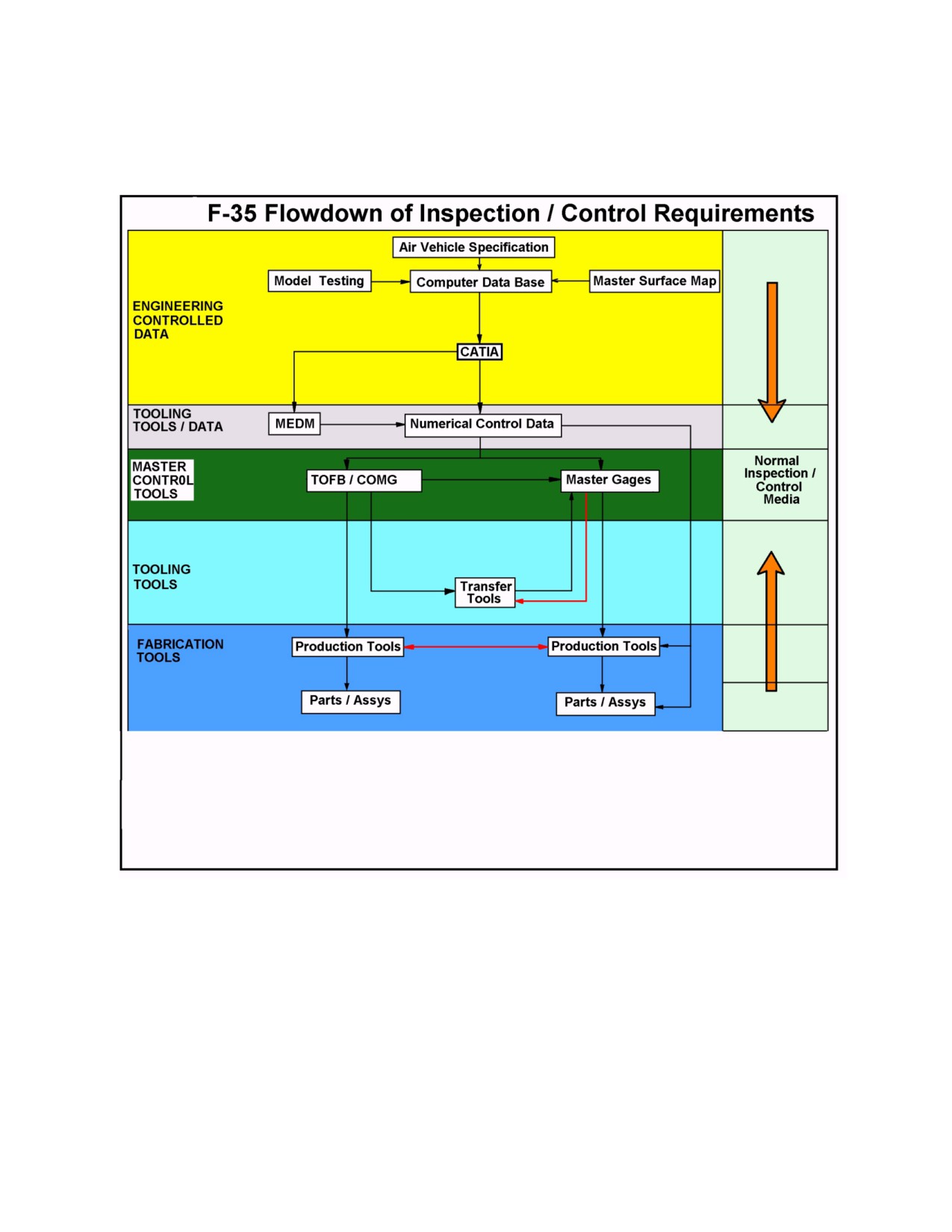
2.7 Order of Precedence for Control Media for Manufacture of the F-35, which defines the Order of
Precedence to be utilized for control, acceptance, and corrective actions of F-35 designs, tooling, and
parts.
3.0 PRESERVATION OF BUYER-FURNISHED TOOLS
* 3.1 To ensure the preservation of Buyer furnished tools, Seller shall:
Provide adequate storage space to ensure Buyer furnished tooling is not abused, stacked,
constrained, or uncontrolled in a manner that may contribute to a loss of configuration.
Maintain all Buyer furnished tools in a rust-free or non-contaminated condition before shipping,
storing, or placing into production.
Prior to each use Seller shall check and replace worn or damaged bolts, nuts, washers, gaskets,
seals, missing or lost items without initiating a SATR, at no cost to Buyer.
>
TMS-MC-015
Revision 30
Page 36 of 104
01 April 2016
Repot or replace loose or worn drill bushings and resurface worn or damaged Non I-R router guide
surfaces while in Seller’s possession when such conditions exist, at no cost to Buyer. Seller shall
not initiate a SATR for such anomalies or conditions unless directed by Buyer via a response to
eSPaR.
Submittal of an eSPaR or SATR shall only be required if the rework or repair task is excessive and
outside the expectations on normal tool maintenance and preservation or if a specified control tool
is required for coordination of a controlled feature of a Buyer furnished tool.
Use and store inside a building and handle with care at all times all fiberglass and composite
tooling to prevent accidental damage to critical points, surfaces, holes, etc.
For fiberglass and composite tools stored in a controlled area other than 75 degrees +/- 10
degrees, Seller shall protect such tools from excessive adverse conditions of heat, cold, sunlight,
and moisture. In addition, when fiberglass and composite tools are subject to temperatures outside
these limits, use such tools only after a period of temperature stabilization.
Ensure a period of 24 hours stabilization for each 10 degree change from 75 degrees which is
necessary to bring the tool back within the approved temperature limits, not to exceed 72 hours.
Fiberglass and composite tools in production shall have the caution label (DS-938) applied at the
next rework or Periodic Inspection/Verification (PI/V) if applicable.
Apply a MIL-C-16173 Grade 2 (light machine oil) protective coating or equivalent to unpainted
alloy surfaces if stored sheltered from the elements, and a MIL-C-16173 Grade 1 (cosmolene)
protective coating or equivalent if stored exposed to the elements. This does not apply to F-35
Program when Conex Containers are used for overseas shipments.
3.2 Cleaning of tool surfaces prior to coating unpainted surfaces shall be by spraying the area to be
cleaned with "Break-Free" cleaning solution (water base, soap, and alcohol solution), or moisten
cheesecloth or clean cotton waste cloth with Break-Free and remove grease, oil, and other contamination
from tool surfaces. Dry the tool with a clean cloth, or use dry compressed air on inaccessible areas. Finally
wipe the area to be protected with cleaning solvent. Protective coating must be applied within 24 hours
after cleaning.
3.3 Rust may be removed from "non-critical" tool surfaces by grinding, sanding, wire brushing, or Jet-Blast
cleaned with dry ice. Rust may be removed from "critical" tool surfaces with a coarse cloth (Scotch-Bright).
Wipe the residue from the affected surfaces with a clean cloth.
3.4 Seller shall comply with the following requirements from the Table for Unpainted Surface Coating for
tool storage:
>
TMS-MC-015
Revision 30
Page 37 of 104
01 April 2016
Table 1.0 Unpainted Surface Coating
Material
Temperature
Storage Sheltered
Storage Exposed To
Required Protection
Controlled
from Elements
Elements
for Shipping
All Metal (Excluding
None
MIL-C-16173 Grade 2.
MIL-C-16173 Grade 1.
MIL-C-16173 Grade 1
Aluminum)
See note 1 and 5
See note 6 below
or 2. See note 1 and 4
below
below
Metal F-22 Tool
None
Ironclad MSDS
Ironclad MSDS
Ironclad MSDS
Storage
#104364. See note 7
#104364. See note 7
#104364. See note 7
Aluminum
None
None
MIL-C-16173 Grade 2
MIL-C-16173 Grade 2
Plywood, Masonite,
None
None
MIL-P-3038 Plastic
MIL-P-3038 Plastic
etc.
Strippable .012, .015.
Strippable .012, .015.
See note 6.
Plaster Forms Co.
Clear Lacquer
Clear Lacquer Trinity
Not Allowed
Clear Lacquer Trinity
Trinity Coating
Coating Co. LC-41 or
Coating Co. LC-41 or
Co. LC-41 or
Equiv. See note 2.
Equiv. See note 2.
Equiv. See note
2.
Metal Accessories
None
MIL-C-16173 Grade 2.
MIL-C-16173 Grade 1.
MIL-C-16173 Grade 1.
See note 3
See note 6
See note 3
Lead and Zinc Alloy
None
None
MIL-C-16173 Grade 1.
MIL-C-16173 Grade 1.
Dies
See note 1
See note 1
Unpainted Surface Coating Notes:
1. Coat critical surfaces plus a one inch margin.
2. Ship or store in boxes - must be securely braced or packed in Bubble pack, Styrofoam, or other
acceptable packing material. Cracked or damaged areas must be recoated with LC-41 lacquer prior to
use.
3. After coating, identify and store with the parent tool. Attach to the parent tool for shipping.
4. For tools sheltered from elements, use Grade 2 film; if the tool is exposed to elements, use Grade 1 film.
For all overseas shipments, use Grade 1 film (cosmolene), unless the tool shipment is by air freight, then
Grade 2 film (light oil) can be used on machined surfaces, in place of cosmolene. Grade 1 film
"Cosmolene" is not applicable to F-35 tools after July 2011.
5. Exception: For Modification Kit Tools (MKTs and MKFs) in SDS997 Plastic Case (kudl-pak) containers
with foam material, use light weight machine oil.
6. If outside storage is unavoidable, prepare per directions in Table 3.16-1. (Grade 1 film "Cosmolene" is
Not-Applicable to F-35 tools after July 2011)
7. Ironclad protective metal coating, reference MSDS #104364, manufacturer ZEP Inc. Atlanta GA. (USA).
Original use was for the F-22 program Tool Storage contract. Ironclad product use in the State of Texas is
controlled by Texas regulations. Seller shall comply with all applicable State usage regulations or
requirements.
3.5 Removal of Grade 1 Film and Iron Clad Coating shall be accomplished by the following options:
3.5.1 Grade 1 Film shall be removed with a scraper, brush, or abrasive pad to remove thick
volumes of cosmolene. Then use one of the following methods for final cleaning Grade 1 Film
(Cosmolene).
• Jet (Ice) Blast
• WD-40 Spray (Use with wipe cloths to remove cosmolene film).
• Pre-Solve Orange degreaser (Ref. MSDS #43563)
3.5.2 Excess Ironclad shall be removed with a scraper, brush, or abrasive pad to remove thick
volumes of Ironclad. Use one of the following methods for final cleaning of excess Ironclad:
• Approved Mineral Spirits materials can be used for removal of Ironclad
• C-200 Consol Solvent (Part: 14074372)
• Pre-Solve Orange degreaser (Ref. MSDS #43563)
>
TMS-MC-015
Revision 30
Page 38 of 104
01 April 2016
3.6 Seller shall provide storage containers for all Master Tooling and Inspection Gages fabricated with
Buyer assigned tool numbers. Seller shall provide containers to specifications identified on the tool design.
Seller shall ensure the containers provide adequate support and protection of tools from the environment
and mishandling during movement.
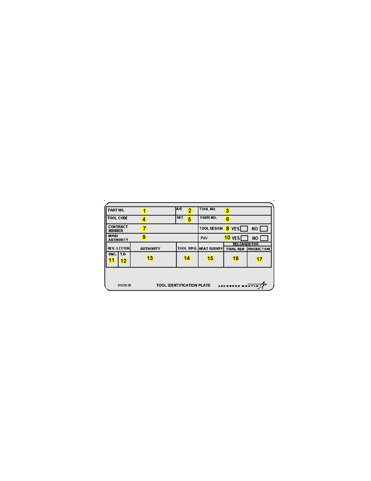
3.7 Buyer furnished tooling identified per PM-4053 identification requirements prior to February 1, 2006
shall be acceptable indefinitely unless rework or repair authorization specifies attachment of a new DS228
Common Tool Identification Plaque for Fort Worth and Palmdale tools. The TNP001 Plaque is applicable
for Marietta tools, if applicable per PM-4053, section 3.8. Such authorization will require the removal and
discarding of any previous identification plaques or stickers with the following exceptions for Legacy
Programs (C-130, C-5, P-3, F-16, etc.):
3.7.1 The use of multiple tool identification plaques on tools will be acceptable only if authorized by
ESPaR request and disposition. Some Legacy Programs require the historical data contained in
sequential tool identification plaques to remain attached to the tool indefinitely.
3.7.2 In all cases, the tool identification plaque with the most current information must be legible. If
current tool identification plaque is worn and not readable, then a new common tool identification
plaque would be required, if applicable by tool type and usage. Reference PM-4053, section 3.8
for specific information required in each block of plaque.
Fig. 1. Typical DS228 Common Tool Identification Plaque
(Highlighted blocks shall require an appropriate entry for each program)
4.0 STANDARD REPAIR TOLERANCES AND COORDINATION
4.1 For standard repair tolerances and coordination of Buyer-furnished tools, Seller shall:
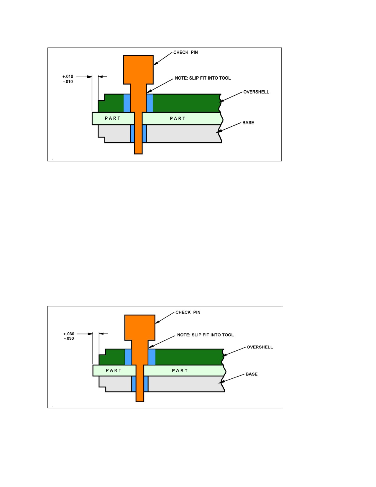
Maintain allowable production tolerances on interchangeable Items produced/verified with
controlled production tooling as illustrated in Figure 2.
Utilize a check pin for all I/R hole patterns to ensure patterns are made in accordance with the tool
coordination tolerance tables included herein.
Utilize controlled production tooling to check and verify allowable production tolerances on
interchangeable Items are from .010 smaller to .010 larger than the tool, as illustrated in Figure 8.
Utilize a check pin to check and verify the I/R hole pattern is made in accordance with the tool
coordination tolerance tables included herein.
>
TMS-MC-015
Revision 30
Page 39 of 104
01 April 2016
Figure 2. DOUBLE RAIL (INTERCHANGEABLE)
Verify replaceable and non-I/R part perimeters produced with production trim tools or check
fixtures have allowable production tolerances from a maximum of .030 smaller, to a maximum of
.030 larger than the tool, relative to the engineering drawing applicable feature tolerance as
illustrated in Figure 3 and 4.
Verify perimeters are plus or minus .030 tolerances, unless otherwise stated on face of drawing.
Example: An E.O.P. dimensioned as +.015, -.030 from a F.S., W.L., B.L. would apply. A "Tab"
dimensioned as + or -.010 for overall width, would apply if stated on the drawing.
Utilize a check pin to verify all I/R hole patterns are made in accordance with the tool coordination
tolerance table.
The use of supplemental tooling such as plaster splashes, fiberglass lay-ups and/or metal tools is
authorized when a coordination tool is not available and such use is approved by program
disposition via an e-SPaR. Such authorized tools shall require Limited First Run and or FAI article
acceptance of the production items.
Figure 3. DOUBLE RAIL (REPLACEABLE, AND NON I/R, NET OR WITH EXCESS)
>
TMS-MC-015
Revision 30
Page 40 of 104
01 April 2016
Figure 4. SINGLE RAIL SETBACK TYPE (REPLACEABLE, AND NON I/R, NET OR WITH EXCESS)
4.2 Holes and MYLAR or Flat Pattern Plots Used For Coordination and Production Acceptance,
Produced tooling holes in Production Items shall have a hole size tolerance of +.005/-.000 and are
located within one-half of such tolerance.
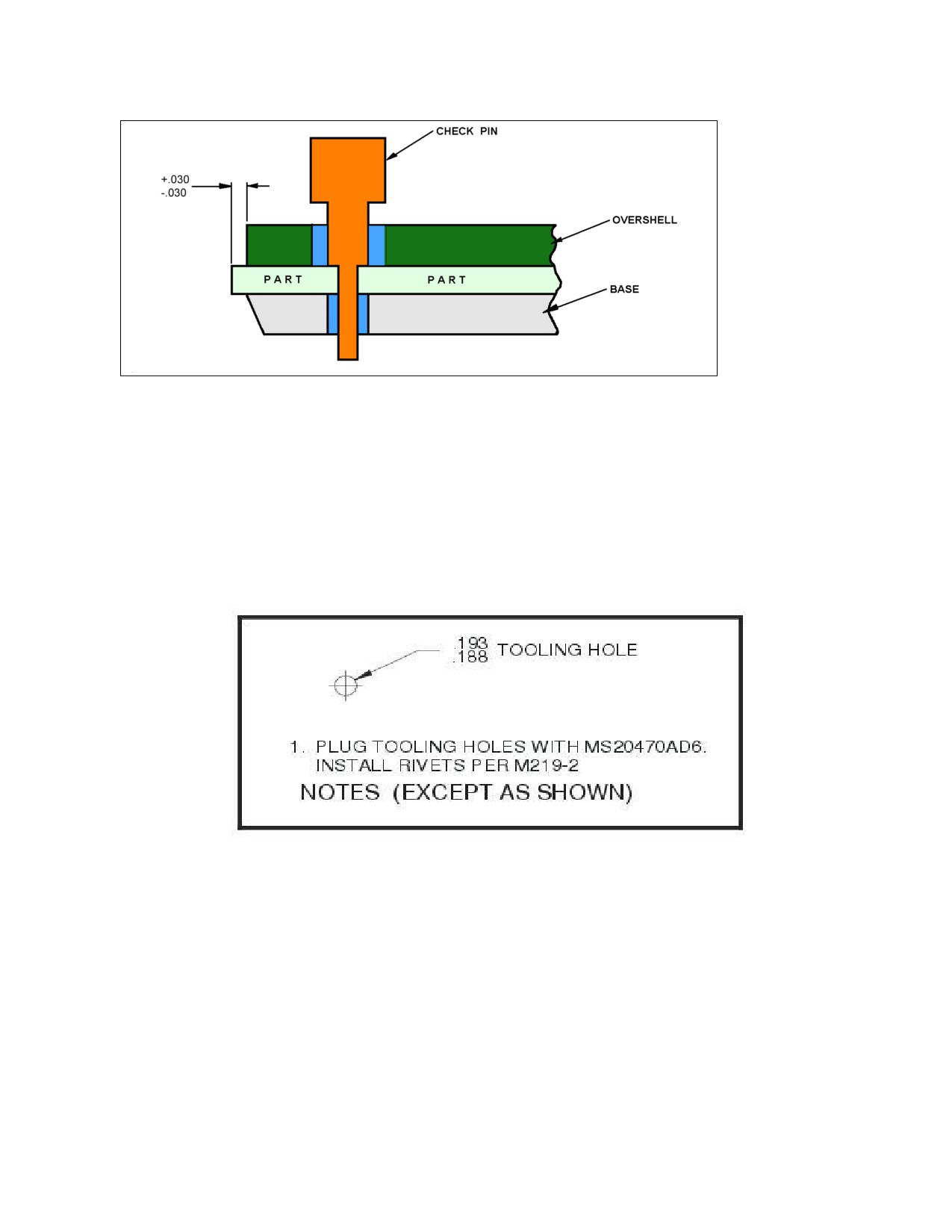
Fort Worth programs generally require Tool Holes to be .187 and Marietta programs require a Tool
Hole size of .250. See PM-4053 section 3.4 and 4.3.
Locate and identify tooling holes on Item(s), as directed by Buyer. When Seller must plug tooling
holes, Seller shall provide a general note to that effect as illustrated below.
Figure 5. Plugged Tool Hole Example
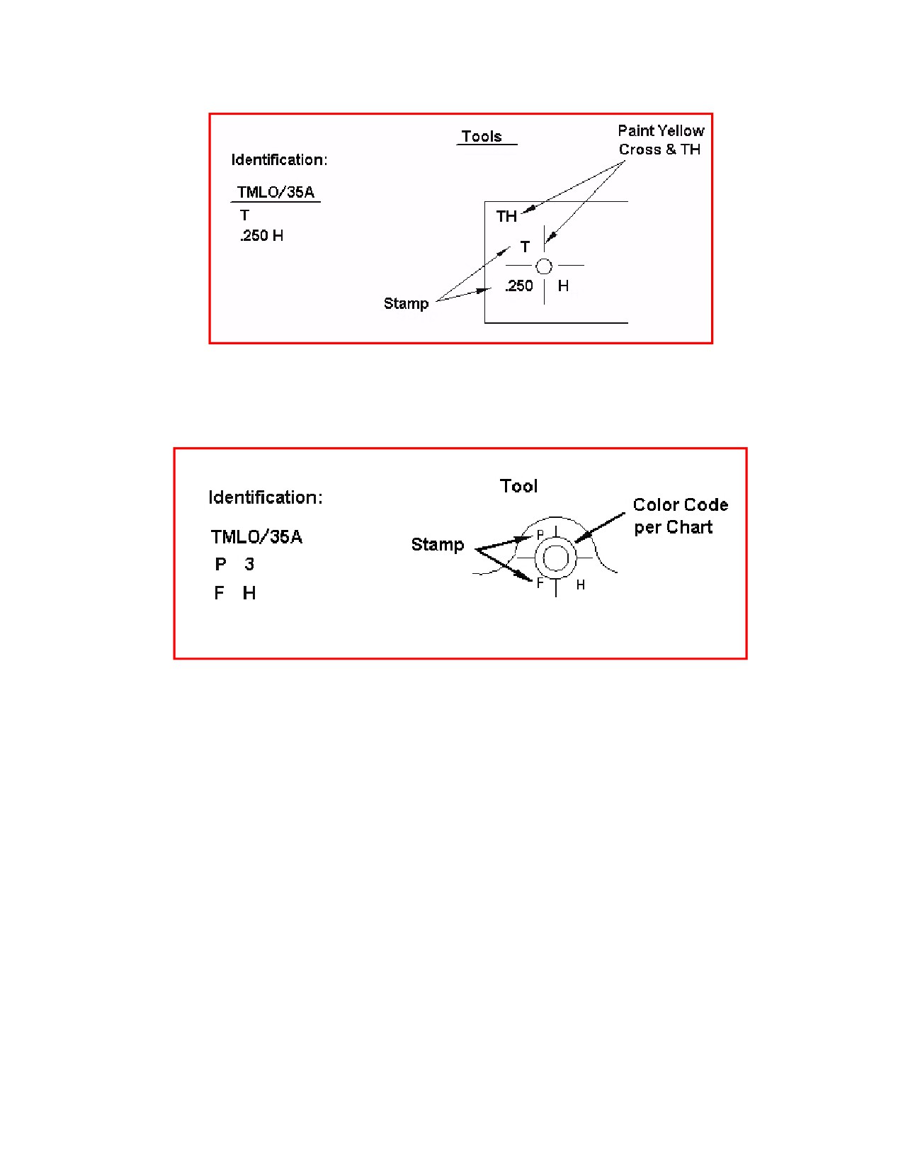
4.2.1 “Tool Holes” are holes used to locate parts through a sequence of fabrication operations or
to locate parts in an assembly tool. These holes are drilled in the part by use of drill bushings.
>
TMS-MC-015
Revision 30
Page 41 of 104
01 April 2016
Figure 6. Typical Tooling Hole and Identification of Tooling Holes
4.2.2 “Pin Holes” are used in sheet metal parts for the purpose of locating part to perform
necessary operations. Normally these holes are in a “tab” or in the excess area of a part. Size is
“F” (.257) diameter unless otherwise specified.
Figure 7. Typical Pin Hole and Identification of Pin Holes
4.2.3 “Construction Holes” are holes placed in the tool for construction and/or inspection of the
tool. These holes must be "soft plugged" in any tool which will be used for a drilling operation,
before released for production use. Identified by painting green. Per Color Code Chart in PM-
4053, section 4.3.
4.3 Mylar’s or any Buyer furnished Engineering Plot shall be utilized as directed by this PO, and tolerances
shall be measured from the center of the plotted line the entire circumference of the part or feature within
the part. Tolerance shall be the width of the line, regardless of line width for non-I/R tooling. Line width is
usually .020 in width. I/R tooling tolerance shall be as noted on Tool Design or Engineering Drawing.
4.3.1. With this method of inspection, set the contour first with specified restraint in the established
plane, if necessary, and then verify the Edge of Part (EOP) or feature to furnished Mylar or Plot.
4.3.2. The Plotted Line is the total tolerance for Non-I/R parts.
*5.0 STANDARD I/R IDENTIFICATION AND REWORK
5.1 Seller shall manufacture, rework, or repair I/R production tooling, only from Buyer Furnished control
media, e.g., Control Tools and Electronic Data, and identify all production tooling establishing an I/R
feature of a deliverable Item to Buyer as follows:
I/R shall be fabricated per applicable program I/R program document for production tools
>
TMS-MC-015
Revision 30
Page 42 of 104
01 April 2016
All I/R identification shall be applied using “Krylon #2101- Cherry Red” Paint
All applicable holes, cut-outs, perimeters, etc., of production tools shall be identified with a ó”
band of the specified paint for all programs except F-35 program, which requires a 1/8” band.
Tooling for the C-130, C-5, and P-3 programs is excluded from the requirement to paint I-R
“features” RED for identification purposes, but shall require the DS-1017 Label for Fort Worth
Tools or a GMN001, GMN002, or a GMN003 Label for Marietta Tools as specified, and the
features shall be identified on the assembly engineering drawing.
The paint shall not be applied to mating, locating, or surfaces subject to wear.
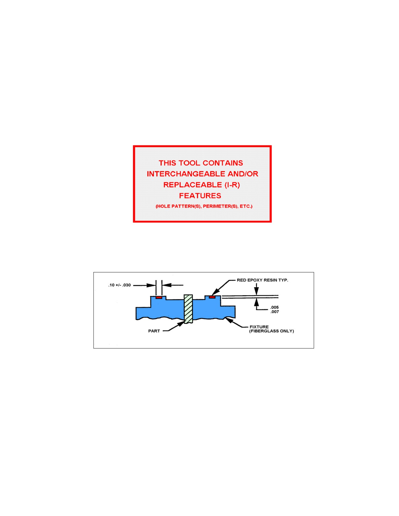
A note applied to tool stating: “This Tool contains Interchangeable or Replaceable (I-R) Features”
in ½” high letters or as practical. Note should be clearly visible to anyone using the tool.
Use of the I/R Identification Label is acceptable as illustrated in Figure 8.
Figure 8. I/R Identification Label
5.2 In addition to the above identification, fiberglass Router Fixtures and Drill Fixtures shall have a special
router guide surface which provides a visual indication of wear. The wear indicator consists of a groove cut
into the I/R perimeter of the tool at a specified width and depth per illustration in Figure 9.
Figure 9. Example of I/R Wear Groove Indicators
>
TMS-MC-015
Revision 30
Page 43 of 104
01 April 2016
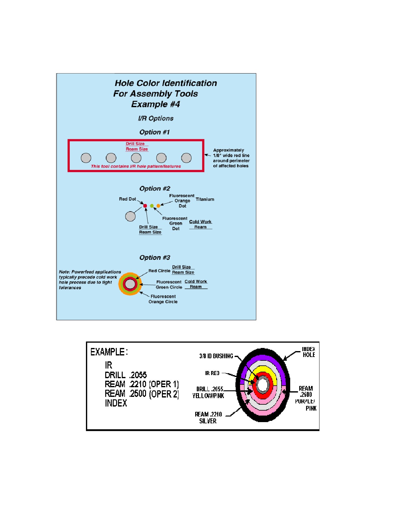
5.3 Seller shall identify F-35 I/R Holes with a 1/8” band of red paint around each hole or group of holes as
illustrated in Figure 10 and Figure 11.
Figure 10. I/R Hole identification Options (All Fort Worth, Marietta: F-35 only)
Figure 11. I/R Hole Identification Example Only
5.4 Unique Tolerances for Legacy Program Tool Holes and Excess Material as specified below.
Non-Designed C-130 and P-3 tools that are controlled by Tooling Tools, shall have a hole size
tolerance of +.001 to -.000, and Pin tolerance for such tools shall be -.0025 to -.0030 per PM-4053
>
TMS-MC-015
Revision 30
Page 44 of 104
01 April 2016
or as specified by this PO or Tool Design, if any, or as directed by Buyers Program Engineering.
Seller shall submit an e-SPaR when discrepancies exist.
Tooling holes may be authorized for detail parts manufacturing or location control during assembly
and may or may not appear on engineering drawing. Sellers shall place tooling holes in detail
parts only after authorization from Buyer’s Program Engineering to avoid potential interference
with subsequent installations.
Material excess tolerance shall be per PM-4053 specification or as Buyer authorized through this
PO to allow deviation from standard tolerance for part manufacturing. Standard tolerance of
+.060/-.030 when material excess call out is .100 up to .250. For material excess greater than
.250, the tolerance shall be +.100/-.060.
5.5 For Control Tool to Production Tool Coordination - Seller shall pin the control tool to the tool being
coordinated with .0000 to .0005 undersize pins at four (4) locations reasonably close to the corners of the
control tool. Seller shall inspect the remaining holes in accordance with pin tolerances shown in Table 2.0
for “Coordination Check of Control Tools”.
5.6 For Control Tool to Control Tool Coordination (Make New) - Seller shall install new control tool
bushings utilizing pins with +.0000/-.0002 tolerance on diameter (Ref.: Transfer of hole pattern, Table 2.0).
5.7 For Control Tool to Control Tool Coordination (Rework) - During rework of control tools bushing, Seller
shall install bushings utilizing pins with +.0000/-.0002 tolerance on diameter. (Ref.: Table 2.0, Transfer of
hole pattern).
5.8 For Control Tool to Control Tool (Coordination Check Only) - Seller shall check the control tool back to
the tool it was made from. During coordination checks of control tools, (Example: MSGA to TOGA), Seller
shall pin four corner holes utilizing pins with +.0000/-.0002 undersize diameter. Ninety percent (90%) of the
remaining holes are acceptable with .0000 to .0010 undersize diameter pins, and the remaining ten
percent (10%) of the holes are acceptable with +.0000/-.0025 undersize diameter pins.
5.9 For Cross-Coordination of Control Tools - When duplicate control tools are fabricated, Seller shall
cross-coordinate control tools in accordance with Table 2.0 "Coordination Check of Control Tools" to
ensure compatibility.
5.10 For Bushing Installation - During the manufacture of new tools and reworks, Seller shall utilize tooling
pins with +.0000/-.0002 tolerance to install all tooling bushings (ref.: Table 2.0 and Table 3.0, Transfer of
hole pattern).
5.11For Inspection of Control Tool Bushing Wear - Seller shall inspect control tool bushings to ensure the
maximum wear is limited in accordance with Table 1.0 and Table 2.0. Seller shall not use any control tools
where bushing wear exceeds the maximum wear tolerance of +.0010 on the inside diameter.
5.12 For tool inspection requirements of I/R tool coordination (applicable to new make, rework, and
coordination orders), Seller shall only utilize check pins which are AISI01 tool steel with a heat treat callout
of RC 55-65 for pins with a diameter of .2500 or larger, and a RC 38-48 for pins with diameters smaller
than .2500.
*5.13 I/R features shall be identified on the Tool Design with flag notes. For I/R tools designed after
01/01/2006, the I/R features will be shown or referenced on the last sheet of the Tool Design to facilitate
tool fabrication, rework, and Periodic Inspection/Verification (PI/V). For the C-130, C-5, and P-3 Programs,
I/R features that are controlled by the tool will be identified by the Production Design Outline (PDO) and
will not be identified on the Tool Design. See Part I, Section 3.0, par 3.7.
>
TMS-MC-015
Revision 30
Page 45 of 104
01 April 2016
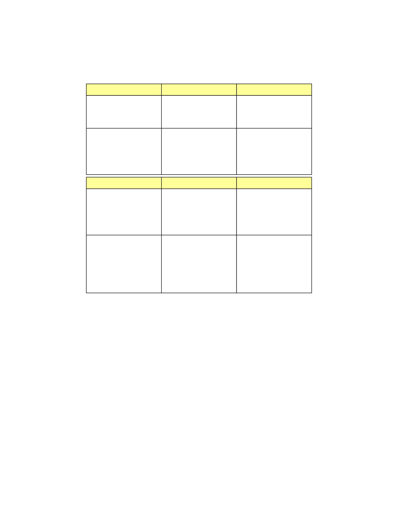
Table 2.0 Coordination Check of Control Tools
HOLES UNDER .250
STRAIGHT PINS
HOLES .250 AND OVER
Transfer of Hole Pattern
Nominal +.0001/+.0004
Bushing I.D. Tolerance
Nominal +.0001/+.0006
Nominal +.0000/-.0002
Pin Tolerance
Nominal +.0000/-.0002
Cross Coordination /
Coord. Check of
Control Tools
Nominal +.0001/+.0010
Bushing I.D. Tolerance
Nominal +.0001/+.0010
Nominal -.0015/-.0020
Pin Tolerance
Nominal -.0020/-.0025
STEP PINS
Transfer of Hole Pattern
(New Make)
Nominal +.0001/+.0004
Bushing I.D. Tolerance
Nominal +.0001/+.0006
Nominal +.0000/-.0002
Lg. Dia. Pin Tolerance
Nominal +.0000/-.0002
Nominal +.0000/-.0002
Sm. Dia. Pin Tolerance
Nominal +.0000/-.0002
.0005 Max
Concentricity
.0005 Max
Cross Coordination /
Coord. Check of
Control Tools
Nominal +.0001/+.0010
Bushing I.D. Tolerance
Nominal +.0001/+.0010
Nominal -.0000/-.0002
Lg. Dia. Pin Tolerance
Nominal -.0000/-.0002
Nominal -.0015/-.0020
Sm. Dia. Pin Tolerance
Nominal -.0020/-.0025
>
TMS-MC-015
Revision 30
Page 46 of 104
01 April 2016
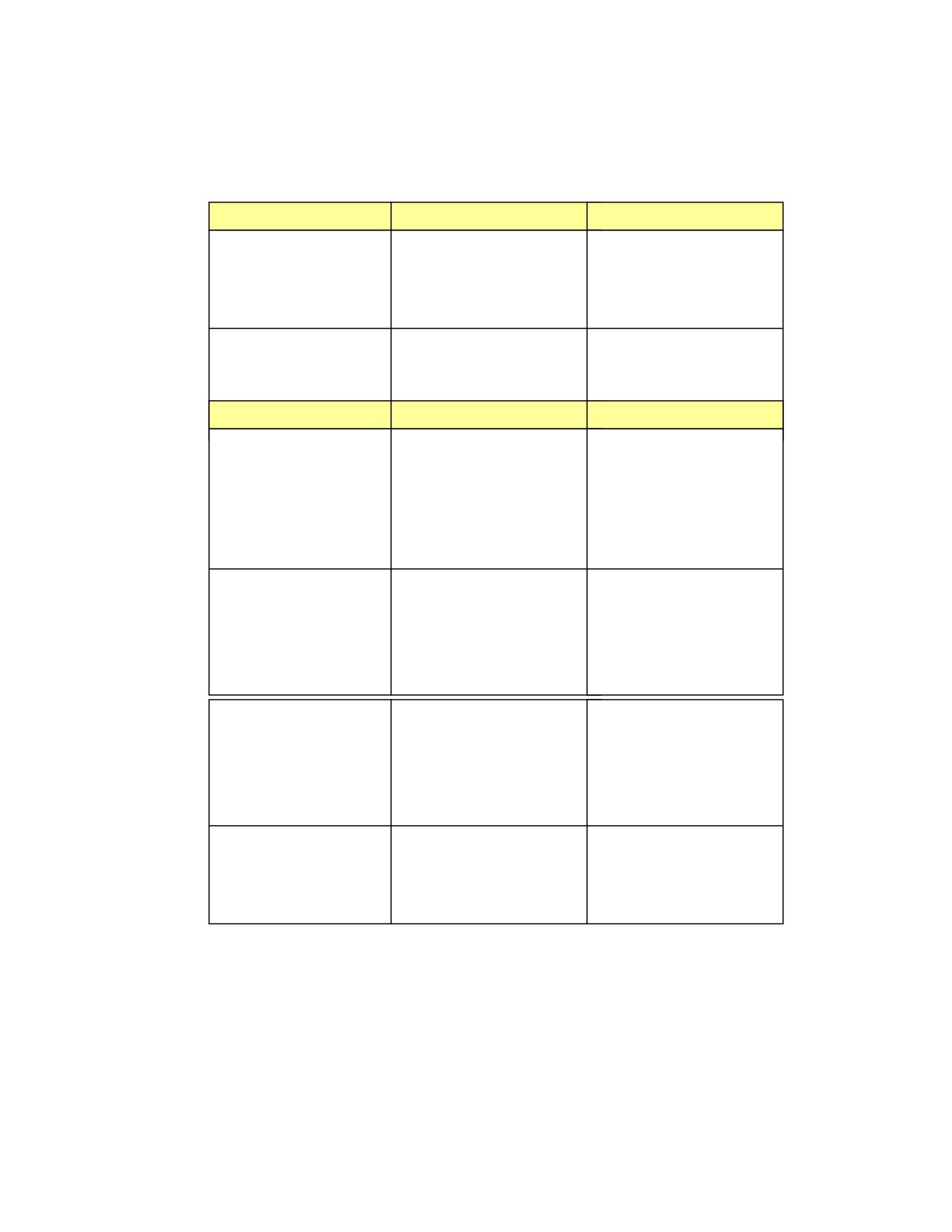
Table 2.0 Coordination Check of Production Tools
HOLES UNDER .250
STRAIGHT PINS
HOLES .250 AND OVER
Transfer of Hole Pattern
(New Make)
Nominal +.0001/+.0004
C/T Bushing I.D. Tolerance
Nominal +.0001/+.0006
Nominal +.0000/-.0002
Pin Tolerance
Nominal +.0000/-.0002
Nominal +.0001/+.0004
P/T Bushing I.D. Tolerance
Nominal +.0001/+.0006
Coordination Check of
Control Tools to Prod. Tools
STEP PINS
Transfer of Hole Pattern
(New Make)
Nominal +.0001/+.0004
C/T Bushing I.D. Tolerance
Nominal +.0001/+.0006
Nominal +.0001/+.0004
P/T Bushing I.D. Tolerance
Nominal +.0000/-.0006
Nominal +.0000/-.0002
Lg. Dia. Pin Tolerance
Nominal +.0000/-.0002
Nominal +.0000/-.0002
Sm. Dia. Pin Tolerance
Nominal +.0000/-.0002
.0005 Max
Concentricity
.0005 Max
Coordination Check of
Control Tools to Prod. Tools
Nominal +.0001/+.0010
Bushing I.D. Tolerance
Nominal +.0001/+.0010
Nominal +.0000/-.0002
Lg. Dia. Pin Tolerance
Nominal +.0000/-.0002
Nominal -.0020/-.0025
Sm. Dia. Pin Tolerance
Nominal -.0030/-.0035
.0005 Max
Concentricity
.0005 Max
Additional Production Tool
Tolerances
Nominal +.0000/-.0002
O/D of Slip Bushing
Nominal +.0000/-.0002
Nominal +.0001/+.0004
I/D of Slip Bushing
Nominal +.0001/+.0006
.0003
Concentricity O/D to I/D
.0003
Hinge Line Tool Tolerances
Nominal +.0000/-.0002
Pins for End Hinges
Nominal +.0000/-.0002
Nominal -.0010/-.0012
Pins for Middle Hinges
Nominal -.0010/-.0012
.0005 Max
Concentricity (end & middle)
.0005 Max
>
TMS-MC-015
Revision 30
Page 47 of 104
01 April 2016
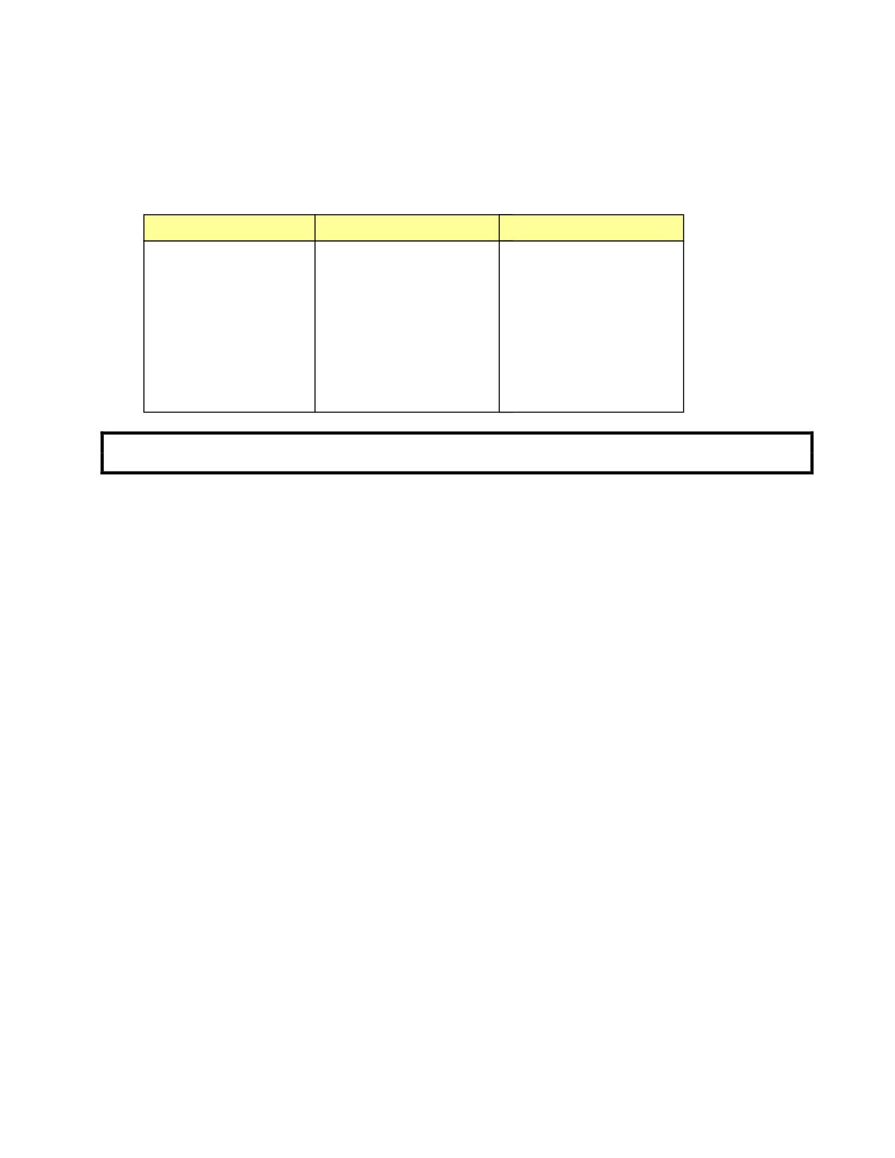
5.14 Seller shall utilize step pins, as illustrated in Table 3.0, to perform a verification check of production
Items to productions tools. Seller shall ensure the check-pin diameter is made to the low engineering
range of the hole diameter being checked with the pin diameter tolerance as shown in Table 3.0.
Table 3.0 COORDINATION CHECK OF PRODUCTION TOOLS
HOLES UNDER .250
STEP PINS
HOLES .250 AND OVER
Coordination of Production
Parts to Production Tools
(Using Step Pins)
Nominal +.0001/+.0010
P/T Bushing I/D Tolerance
Nominal +.0001/+.0010
Nominal +.0000/-.0002
Lg. Dia. Pin in Tool
Nominal +.0000/-.0002
Nominal +.0000/-.0030
Sm. Dia. Pin in Part
Nominal +.0000/-.0030
.0005 Max
Concentricity
.0005 Max
C/T - CONTROL TOOL
I/D - INSIDE DIAMETER
P/T - PRODUCTION TOOL
O/D - OUTSIDE DIAMETER
*5.15 Seller shall verify I/R tooling tolerances are as follows:
Master Tooling is net (nominal).
Master Tooling to Production Tooling for contour shall be +/- .015 over 80% of gauging surface
and +/- .020 over 20% of the surface per PM-4053. I/R Production Tool Design will specify
features that are coordinated to Master Tooling. All other Tool Design specifications are to be
maintained per I/R Tool Design.
Production Tool to production Item tolerance for contour is .000 to +.020.
o Note: This tolerance is a tooling application which recognizes the engineering drawing
tolerance of +/- .010, unless otherwise specified, for sheet metal Item contour relative to
Item being placed against a solid tool surface for checking. The tooling application also
recognizes restraint in the tool, in accordance with the engineering drawing.
Indenture tool development does not exceed +/- .005 total back to the master.
Buyer-furnished Master Control Tooling is not used for production purposes, i.e., Item verification,
trimming, drilling, and forming.
5.16 Seller shall verify non-I/R tooling perimeter, holes, and contour tolerances are as follows:
Non I-R Tooling Tools are net to engineering, unless otherwise identified on tool, i.e., excess on a
tooling sample. Excess tolerance shall be per PM-4053 specification or as Buyer authorized
through this PO to allow deviation from standard tolerance.
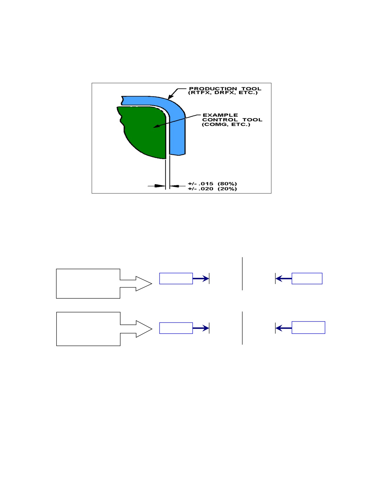
Surface tolerance from tooling tool to controlled production tooling is +/- .015” tolerance allowable
over 80% of the gauging surface, and +/- .020” over 20% of the gauging surface as illustrated in
Figure 12.
Tolerance from controlled production tooling to production Item equals +/- the engineering drawing
tolerance, for edge and/or cutout trim and holes.
>
TMS-MC-015
Revision 30
Page 48 of 104
01 April 2016
Controlled production tool to production Item tolerance for contour is .000 to +.020.
Figure 12. Production Tool to Control Tool
5.17 Seller shall verify Seller-developed tools yield an Item not to exceed +/- .010 variance from applicable
Master Control Tooling or Buyer Furnished Tool for the purpose of Seller development or production tool
manufacturing.
5.18 Seller shall verify coordinated tool holes are direct pinning without undue interference.
5.19 I/R Tooling tolerance examples:
MASTER TOOLING
M. Tool
.005
.005
P. Tool
TO PRODUCTION
TOOLING
+/- .005 (MASTER TOOL TO PROD. TOOL)
PRODUCTION
TOOLING
P. Tool
.010
.010
P. Part
TO PRODUCTION
PART
+/- .010 (PROD. TOOL TO PROD. ITEM)
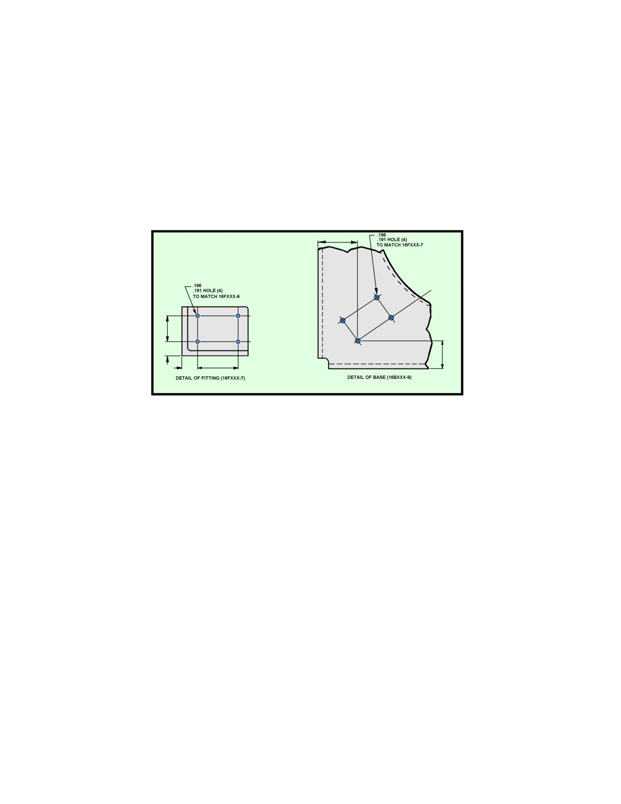
6.0 “TO MATCH” HOLE PATTERNS AND OTHER I/R FEATURES
6.1 The term “To Match”, when specified on Buyer engineering drawings relative to hole locations,
indicates that the dimensions including tolerances, even when met, may not necessarily ensure physical
mating of Item hole patterns at the point of installation. This is true even though from a dimensional
standpoint, the features are within engineering drawing tolerance limits. “To Match” features are physically
established, within engineering drawing tolerance limits, through the use of Master Tooling. Once Seller
physically establishes the features, Seller must maintain the actual positions to achieve and sustain “To
Match” capability (example in Figure 13).
>
TMS-MC-015
Revision 30
Page 49 of 104
01 April 2016
6.2 Buyer’s Tooling specification, relative to Item features requiring physical control for configuration
management purposes, is to provide Control Media, e.g., master gage, tooling gage, master plate, MEDM,
or other Electronic Data, to establish and maintain those Item features requiring control, over and above
only the engineering drawing dimensions and their associated tolerances. If the Item feature requiring
control has a critical configuration relationship requirement to other Item features, the Control Media will
also establish those Item feature relationships, one to the other. Additionally, even though Item features
may be within engineering drawing dimension tolerance band for those features, if an actual feature
location does not comply with applicable Control Media allowed tolerance deviation, the feature location is
not acceptable.
6.3 Buyer’s Control Media drawing, if applicable, will denote maximum tool deviations permitted in feature
location or relation to critical features that are acceptable on finished Items.
Figure 13. Example of “To Match” hole patterns as defined on engineering drawings.
7.0 SHIPPING AND STORAGE CONTAINERS FOR BUYER FURNISHED TOOLS
7.1 Domestic shipping and storage containers can be one in the same for Control Media Tooling, e.g.,
Master Gage, or Inspection Gage if appropriate.
7.2 Seller shall request from Buyer, a hard copy of the appropriate Container specifications applicable to
this PO when Seller has not been granted access to PM-4053. Containers that will serve a dual purpose of
shipping and storage shall also be identified as required in PM-4053, section 3.8, and manufactured per
requirements in section 3.16, or as specified by Tool Design or this PO.
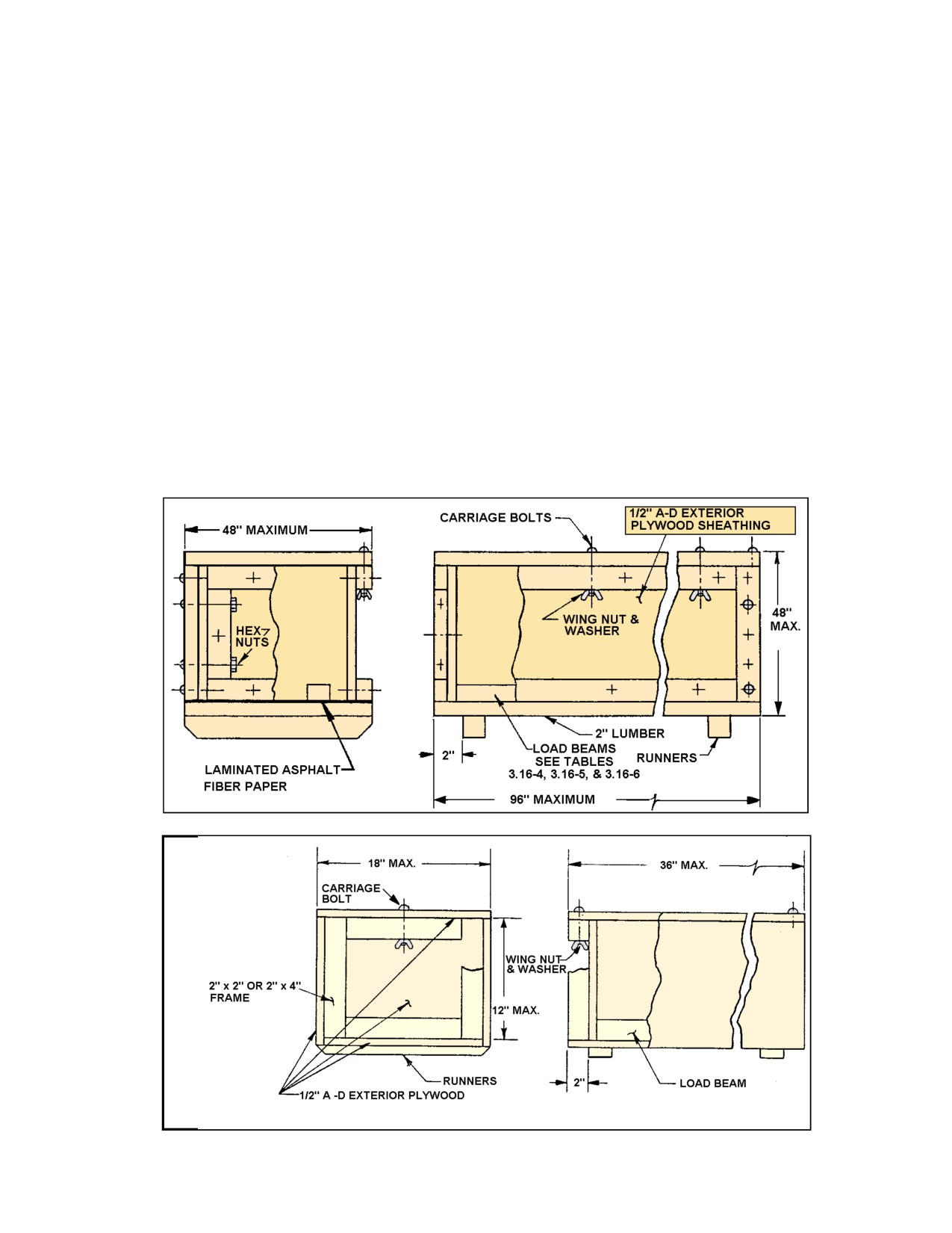
7.3 The following Tools require a wood shipping and storage container manufactured per PM-4053,
section 3.16.4;
• FCGA (Facility Gage)
• FG/30E (Facility Gage) (MAR)
• COMG (Component Master Gage)
• MCG/24E (Master Control Gage) (MAR)
• MG/14E (Master Gage) (MAR)
• MHLT/26A (Master Hole Layout Template) (MAR)
• MSPE (Master Plate)
• MSGA (Master Gage)
• COTG (Component Tooling Gage)
• TOGA (Tooling Gage)
7.4 The following Tools do not require a storage container, but Seller shall store and ship in a manner that
will prevent damage, unless otherwise instructed by this PO.
>
TMS-MC-015
Revision 30
Page 50 of 104
01 April 2016
•FTP/21E (Fabricated Tooling Pattern) (MAR)
• MM/13E (Master Model) (MAR)
• MSFM (Master Form)
• MSTP (Master Template)
• MTT/33A (Master Tooling Template) (MAR)
• PM/20E (Plaster/Plastic Model) (MAR)
• TOFA (Tooling Form)
• TOFB (Tooling Form)
• TOFM (Tooling Form)
• TOPA (Tooling Pattern
• TOSE (Tooling Sample)
• TOTP (Tooling Template)
7.5 Shipping containers for Control Tools shipped to International Coproduce or overseas shipment shall
be Type I or Type II-3 or Plastic SDS997 containers when appropriate for smaller tools per PM-4053,
section 3.16.4 and 3.16.5.
7.6 Production Tool (non-gage tool) containers shall require Type I, II, or III containers for tools.
F-35 program specifies unique shipping and container requirements in PM-4053, section, 3.16.5.
Figure 14. Example of Type I Container
>
TMS-MC-015
Revision 30
Page 51 of 104
01 April 2016
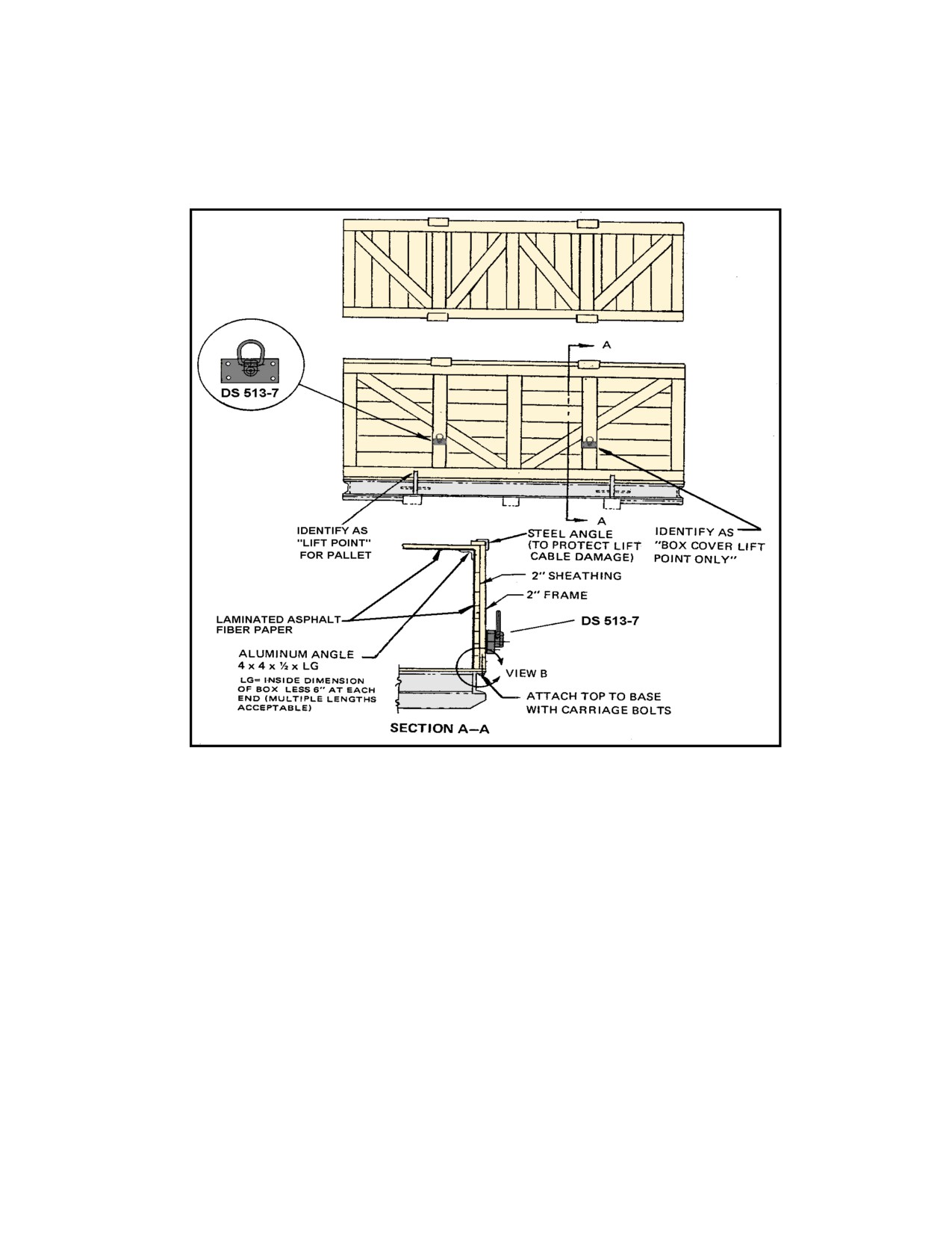
Figure 15. Example of Type II-3 Container
7.7 Larger Tools shall require containers unique to their specific size and shall be manufactured per
requirements for Type I-4 containers.
Figure 16. Example of Type I-4 Container for Large Tools
8.0 BUYER FURNISHED TOOLING AND SELLER TO SELLER TRANSFER OF TOOLS
8.1 Sellers authorized by Buyer to ship tools to another Seller shall ship tools according to Buyer
authorization and Part I, section 10.0 of this Manual.
8.2 Sellers authorized by Buyer to receive tools from another Seller shall re-verify Buyer transferred or
Buyer Furnished tooling in addition to the requirements set forth in this Manual for receipt of tooling in Part
I, section 6.0.
8.3 As part of the receiving requirements, Seller shall be responsible for documenting condition of Control
Tools upon receipt, including completing accompanying records within the container per Part I, section
10.3.
9.0 SET-UP PROCEDURE FOR FLOOR BASED ASSEMBLY JIGS
>
TMS-MC-015
Revision 30
Page 52 of 104
01 April 2016
9.1 Seller shall utilize the following guidelines for Major Assembly Jigs and Gages utilized for assembly as
re-verification criteria upon receipt. Conformance to the following criteria, Tool Design drawing, PM-4053
and the specific Jig reference system values shall constitute satisfactory acceptance criteria;
Visually inspect the jig upon receipt for obvious signs of damage sustained during shipment. All
discrepancies or damage shall be documented and submitted to Buyer for rework/repair
disposition, via Supplier Aircraft Tooling Report (SATR).
Continue to locate the jig into position, if applicable, taking care to secure areas of the rough
structure and avoid contact with locating features. Verify that the jig rests on all jack screws and
jig feet provided.
Rough level the jig using a conventional optical level and the leveling buttons located along the
peripheral rough-structure near each jack screw. Allow the jig to sit overnight (24 hours) to
normalize to the environmental conditions under its own weight. Temperature and humidity
readings shall be documented throughout the process if Laser verification is utilized for this
process.
Remove grease or other preservation treatments from the jig and loosen any pins and/or bushings
that may have corroded during shipment.
Install permanent details such as counter-balances, etc., that were temporarily removed for
shipping and check to ensure proper function.
Remove and establish storage means for removable details for each jig.
Level the jig (horizontal plane) as necessary to maintain +/- .005 inches tolerance.
Verify the plumb (vertical plane) of the jig to within +/- .005 inches tolerance. Use buttons where
they are provided or the candlestick mounts common to the jig Lines Of Sight (LOS) for this
purpose.
Note: It is sometimes necessary to adjust the level of the jig slightly in favor of the plumb in order
to avoid excessive twist.
Set-up and establish the jig reference system using the Laser Tracker targeting system (or
equivalent) based on the coordinates provided on the jig. Target points and identification tags with
values are stamped on each jig for this purpose.
Measure the position of the candle-stick mounts, if applicable, per Tool Design drawing. Typically,
there are four (4) mounts. Work from forward to aft along the Basic (lower) Line-Of-Sight (LOS),
and then along the Auxiliary (upper) LOS. Observe squareness of the points and maintain within
005-inches total tolerance reading. The Auxiliary LOS is allowed run-out in the Z-axis (Water
Line), but not in the X-axis (Buttock Line).
Measure the position and alignment of the end-plates on the respective jigs to the basic and
auxiliary LOS criteria per Tool Design drawing.
Measure and create a y-axis (Fuselage Station) plane on the forward end-plate. The y-value
should correspond to the nominal value shown on the tool design drawing and be planer within
.010-inch total tolerance reading.
Measure and create a y-axis (Fuselage Station) plane on the aft-ward end-plate as in the previous
step. The y-value should correspond to the nominal value shown on the Tool Design drawing and
be planer within .010-inch total reading. Observe the overall length of the jig between the end-
plates and verify parallelism to +/- .010 inches tolerance.
>
TMS-MC-015
Revision 30
Page 53 of 104
01 April 2016
Anchor jig to floor as specified and illustrated in PM-4053, if applicable to tool type.
Document all readings or damaged conditions noted in the steps per Part I, section 7.0 of this
Manual.
Submit SATR forms to document damage and out-of-tolerance conditions for rework/repair
authorization, if any is required.
Rework or repair any damaged tool details and out-of-tolerance conditions dispositioned by Buyer
according to tool design drawing or special instructions. For C-130 and P-3 program, Seller shall
make note of the completion of all verification points, inspection data, and rework or repairs within
the “Tooling Inspection Record” Form 1856-2 accompanying each jig.
Perform additional inspection/verification items as requested by Buyer’s Representative, if
applicable.
Establish periodic inspection points and records for future dimensional stability checks by verifying
these key features during this initial set-up process. See Part I, section 11.0 of this Manual for PI/V
requirements.
Verify or install a new DS-228 Tool Identification Tag, if required on all tools per PM-4053, section
3.8. Stamping and dating of Tool Identification Tag shall be accomplished as directed by Buyer’s
Representative.
Tool shall be placed into use for Trial Run/Tool Proof/FAI activity only.
Tool shall not be released for Production service until successful Tool proofing activity is
completed.
END OF APPENDIX A
>
TMS-MC-015
Revision 30
Page 54 of 104
01 April 2016
APPENDIX B - AIR FRAME TOOL CODES AND DEFINITIONS
1.0 SCOPE
1.1 Due to requirement changes, revisions and evolution of Legacy programs, the following air frame tool
codes and descriptions are provided as a reference to understanding specific tool types, basic functions or
intended use when either specified or referenced in this PO. If Seller is in possession of a Buyer Furnished
tool that is not listed on this reference chart, Seller shall submit e-SPaR per Part I, para 2.12 requesting
clarification or definition of use for each tool.
1.2 Table 5.1 identifies all Marietta Programs Tool Codes and their descriptions and Table 5.2 identifies all
Fort Worth Programs Tool Codes and their descriptions.
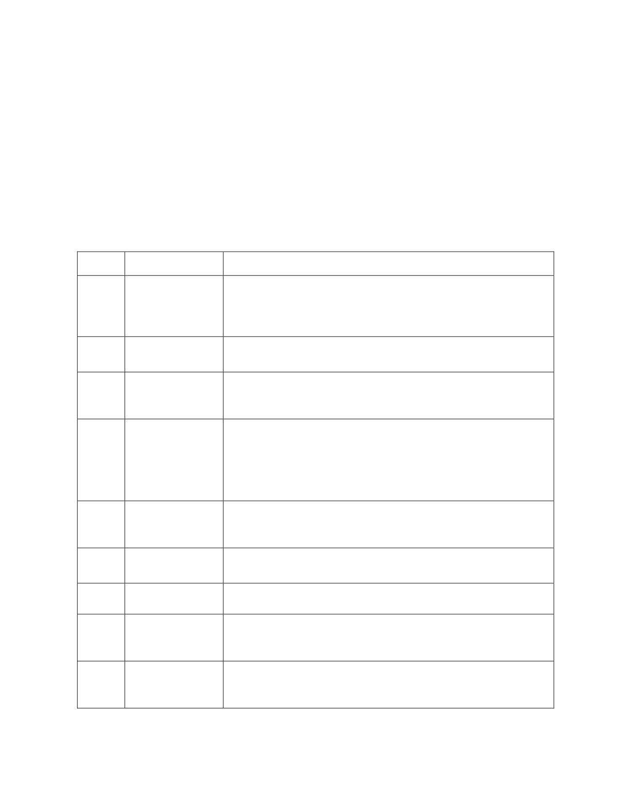
Table 5.1 Marietta All Programs Tool Codes
Tool
Nomenclature
Description
Code
11A
DEVELOPED
A DEVELOPED LAYOUT TEMPLATE is a flat metal guide or index tool
LAYOUT
used by Tooling or Manufacturing to define part outlines and hole
TEMPLATE
locations, if the nature of forming permits development by layout
methods. It can also include other guiding or indexing information
similar to a Flat Tooling Template (10A).
11B
FORM BLOCK
A FORM BLOCK is a cast or fabricated forming tool used by
Manufacturing to bench-form parts not suitable for machine forming. It
may be a simple form block or a simple bending machine or device.
11C
DRILL JIG
A DRILL JIG is used by Manufacturing to hold a part while performing
drilling and reaming operations. A Drill Jig positions and clamps the
part against positive locators and provides bushed holes for guiding the
drill or reamer.
11D
BLANK DIE
A BLANK DIE is a conventional punch press tool used to blank the
profile of flat metal parts; however, it has limited application in blanking
parts that have a slight contour produced by a previous forming
operation. The punch and die details are mounted in a die set. The
part and the scrap material are released from the die by positive action
or spring loaded strippers, but the part normally must be manually
removed from the die.
11G
MISCELLANEOUS
A MISCELLANEOUS TOOL is a one-of-a-kind, special tool required for
TOOL
an unusual production operation or tooling use. Because of its unusual
nature, its description does not fit any other active tool code. Also, it is
unlikely additional similar tools will be required in the future.
11H
SLING
A SLING is a lifting tool that attaches to or supports an aircraft
part/assembly and provides proper balance for safe handling, through
the use of an overhead crane or similar equipment.
11N
NC TAPE
NC TAPE is a tape that can be made from various types of media and
is used to control the cutting action of a computer controlled machine.
12C
FLOOR
A FLOOR MOUNTED ASSEMBLY JIG is a locating and clamping tool,
MOUNTED
which provides the means for holding detail parts or sub-assemblies in
ASSEMBLY JIG
accurate relative position for assembly. It is large enough to require
permanent floor mounting.
12D
PIERCE & BLANK
A PIERCE & BLANK DIE is a conventional tool used to pierce holes
DIE
and blank the periphery of parts in a punch press. It may be a
compound, one stage, or a progressive, two stage, die at the discretion
of the Tool Designer.
>
TMS-MC-015
Revision 30
Page 55 of 104
01 April 2016
Tool
Nomenclature
Description
Code
12E
SAMPLE PART
A SAMPLE PART is a Manufacturing or Tooling aid provided as a
project tool. It is a dummy of a part or assembly and its configuration
varies according to intended use. It is used by Manufacturing to make
standard setups on machines and by Tooling to fabricate other tools.
12H
SUPPORT
A SUPPORT FIXTURE is a holding tool used by Manufacturing to
FIXTURE
support an assembly in a position suitable to perform additional work in
an out-of-jig position.
13A
ABBREVIATED
An ABBREVIATED FLAT TEMPLATE is a flat pattern of a portion or
FLAT TEMPLATE
portions of a part. The template may include joggles, end detail, trim
detail, external cutout detail fabrication lines, production hole patterns,
pin holes and tooling holes.
13B
HYDRO BLOCK
A HYDRO BLOCK is a forming tool used by Manufacturing to form a
part by direct application of hydraulic pressure against forming
surfaces. The block is in fact a punch upon and around which metallic
parts are formed.
13C
ASSEMBLY TRIM
An ASSEMBLY TRIM JIG is a profiling guide tool used by
JIG
Manufacturing to trim a large or complex part or assembly.
13D
STEEL RULE DIE
A STEEL RULE DIE is a length of spring steel tape used for marking
drill holes or locating points across large parts or assemblies. The
steel tape contains marks which have been applied in accordance with
a tool design, and those marks indicate the points where scribe lines or
punch indentations are to be applied.
13E
MASTER MODEL
A MASTER MODEL is a control tool used by Tooling as a reference
master for constructing various project tools. These tools will be
constructed from the model within tooling transfer limits. It is a full-
scale replica of a contoured portion of an airplane. It is built as close to
the Engineering data as is practical and represents the theoretical
Engineering data after its completion. The model represents basic
criteria which has no tolerance. The model has a reference system
(butt lines, station lines, water lines, etc.) and often uses basic lines of
sight as the origin of the reference system.
13F
RESISTANCE
A RESISTANCE WELD JIG is a locating and clamping tool consisting
WELD JIG
of a framework with sufficient clamping and locating means to hold two
or more parts in accurate relative position and to provide access for
spot or resistance welding.
13H
DOLLY
A DOLLY is rolling equipment used to transport heavy parts, sub-
assemblies, assemblies and tools.
14A
RADIAL DRILL
A RADIAL DRILL TEMPLATE is a flat metal guide or index tool used by
TEMPLATE
Tooling or Manufacturing to define part outlines and hole locations, if
the nature of forming permits development by layout methods. It can
also include other guiding or indexing information, if specified, enabling
operations such as piercing, drilling, spot facing, countersinking and
dimpling.
14C
AUTOMATIC -
An AUTOMATIC - RIVETING JIG is an assembly tool used by
RIVETING JIG
Manufacturing to position and hold an assembly during an automatic
riveting operation. It can be either a portable semi-automatic type
(manipulated by hand); or a stationary fully-automatic type (mounted in
a fixed position on a machine-controlled bed). The ARJ/14C holds two
or more parts in proper relation to each other while an automatic
riveting machine punches or drills a hole and inserts and heads a rivet.
>
TMS-MC-015
Revision 30
Page 56 of 104
01 April 2016
Tool
Nomenclature
Description
Code
14D
HAMMER DIE
A HAMMER DIE is a forming tool used by Manufacturing to form sheet
metal parts. It consists of a punch and a die which is mounted in a
drop hammer. The punch is usually male, made to the inside of the
part, and the die is female, make to the outside of the part.
14E
MASTER GAGE
A MASTER GAGE is a control tool. It is used by Tool Manufacturing
and Tool Inspection to control production tooling for inter-
changeable/replaceable end items such as access panels, ailerons,
doors, flaps, etc. It is normally a partial replica of the critical mating
points (holes, hinge center lines, surfaces, contours, edges) of the item
it represents.
14F
WELD JIG
A WELD JIG is a locating and clamping tool used to hold two or more
parts in accurate relative position and provide access for flame or arc
welding. It consists of a framework with sufficient clamping and
locating means to hold the parts and is made of any suitable material.
15A
SET-UP
A SET-UP TEMPLATE is a flat metal template type tool used by
TEMPLATE
Manufacturing to spot spray rivet locations or to position details on the
standard scribe tables for the layout of Chem-Milled parts.
15B
FORMED PIN
A FORMED PIN ROUTER BLOCK is a profiling tool, used on a pin
ROUTER BLOCK
router by Manufacturing. The tool has Guide slots on the underside of
the base which controls the movement of part past the router bit as the
tool is moved for the cut. The part is guided against a pin on the router
table which is in line with the router bit. The tool consists of a base
plate, nesting blocks, suitable clamps and tool-handling handles.
15D
FORM DIE
A FORM DIE, FD/15D, is normally a single operation forming tool used
primarily as a bending tool, although drawing or stretching might occur.
It may be designed for various forming methods such as punch or
hydraulic press, brake press, hydro press, electric discharge, electro-
magnetic, etc. The forming action can be by impact or application of
controlled pressure.
15E
TOOLING MODEL
A TOOLING MODEL PART is a tool that is a replica of a part or
PART
assembly (which may be abbreviated) used in the tool shop for
coordination purposes only.
15H
FLOORBOARD
A FLOORBOARD is a portable protective covering that is used as a
walkway or work platform on or in an aircraft assembly.
16A
CHEM-MILL
A CHEM-MILL TEMPLATE is a tool used as a guide in removing the
TEMPLATE
neoprene or plastic maskant from production parts in the area to be
chemically milled.
16B
RADIAL-ARM
A RADIAL-ARM ROUTER BLOCK is a flat guide block used by
ROUTER BLOCK
Manufacturing to profile part blanks. It is used on a standard radial-
arm-routing setup, which consists of fastening the block over the
material and to the router table; hold-down screws through pin holes
within the part or in tabs outside the part are used.
16D
DRAW DIE
A DRAW DIE is a double-action forming tool and is used by
Manufacturing to draw-form sheet metal parts. It consists of a punch
made to the inside of part contour, a die made to the outside of part
contour, and a draw ring or pressure pad which is spring, air or
hydraulically loaded.
16F
LOCATING
A LOCATING FIXTURE is an installation tool that indexes to pre-
FIXTURE
established surfaces and/or holes and provides locating and clamping
devices for performing additional assembly operations.
16H
HOIST
A HOIST is a lifting tool such as a windlass, winch or elevator, and is
usually air or electrically powered.
>
TMS-MC-015
Revision 30
Page 57 of 104
01 April 2016
Tool
Nomenclature
Description
Code
17A
ANGLE
An ANGLE TEMPLATE can hold two or more parts in relative position
TEMPLATE
for checking or assembly. It can also serve as a tooling tool to be used
in the fabrication of other special tooling.
17B
PIN ROUTER
A PIN ROUTER BLOCK is a flat guide tool used by Manufacturing to
BLOCK
profile flat part blanks on a pin router or shaper. It is made to the net
profile of the part blank. The part blank is stacked on top of the block
and clamped, using standard router clamps.
17D
STRETCH FORM
A STRETCH FORM DIE is a male forming tool used by Manufacturing
DIE
to form parts by stretching sheet stock, under tension, around the tool
profile. The tool, or punch, is made to the inside contour of the part.
17E
JIG DRILL PLATE
A JIG DRILL PLATE is a guide tool for hand and/or portable power
positive feed drilling of hole patterns in sub-assemblies. It may contain
features for indexing and for clamping to another tool, or, to a
production assembly. It may be a template, flat plate, fiberglass lay-up
or a framework, and is made in accordance with best tooling practices.
17F
SAW FIXTURE
A SAW FIXTURE is a guide tool used to nest and clamp parts or
assemblies in a definite relationship to a saw or abrasive cut-off wheel.
It is made from any suitable material and is generally
18A
APPLY TRIM-&-
An APPLY TRIM-&-DRILL TEMPLATE is a flat or formed nesting guide
DRILL TEMPLATE
tool. While essentially a guide tool (applied to a part while operations
are being performed), it can also be built as an index tool (setting stops
or guides of machines or tools).
18B
SHAPER BLOCK
A SHAPER BLOCK is a guide block used by Manufacturing to profile
formed sheet metal or extruded parts on a spindle shaper. The edges
of the block guide the profiling cut by moving against a guide collar on
the shaper. It has nest blocks, locators, end stops and clamps for
locating and securing the part.
18C
ASSEMBLY
An ASSEMBLY CEMENTING FIXTURE is a tool that holds two or more
CEMENTING
product parts in proper relation to each other while they are joined by
FIXTURE
cementing or adhesives. This tool includes features to locate the parts
and details to provide mechanical clamping action when necessary to
retain the parts being assembled.
18E
CHECK FIXTURE
A CHECK FIXTURE is a tool which is used to physically inspect and
control formed parts or assemblies within specified dimensions and
tolerances. It can be a nest type tool, a base with contour locators, a
sheet metal template or any configuration needed to check the part or
assembly. It also may include provisions for scribing end of part.
18F
MILL FIXTURE
A MILL FIXTURE is a locating and clamping tool used to locate a part
or parts in a definite relationship to a milling machine table and cutters.
It has part locators and clamps, or a clamping device such as a
vacuum chuck, and may include cutter set blocks or a touch-off button.
Clamps to machine table.
19A
APPLY TRIM-&-
An APPLY TRIM-&-DRILL TEMPLATE is a flat or formed nesting guide
DRILL TEMPLATE
tool. While essentially a guide tool (applied to a part while operations
are being performed), it can also be built as an index tool (setting stops
or guides of machines or tools).
19B
STRETCH FORM
A STRETCH FORM BLOCK is a forming tool that may include
BLOCK
supporting tooling units such as stretch jaw inserts (set), joggle forming
devices, and snakes (flexible filler tool to maintain the shape of certain
cross-sections of extrusions or brake formed parts during the forming
operation). These blocks are always made to a convex contour and
usually to a net contour, but some blocks may require "spring back"
allowance incorporated in them.
>
TMS-MC-015
Revision 30
Page 58 of 104
01 April 2016
Tool
Nomenclature
Description
Code
19E
MISCELLANEOUS
A Misc. Pattern Equipment is a pattern fabricated of wood and metal
PATTERN
which is use to impress a shape in sand to create the cavity in which to
EQUIPMENT
pour molten aluminum.
19F
LATHE FIXTURE
A LATHE FIXTURE is a centering and clamping tool, used for
machining cylindrical or spherical surfaces on a part or parts. These
may be internal, external, eccentric or any combination of these. It
consists of a base or frame which is adapted to a lathe spindle, lathe
chuck, face plate or chuck jaws. It has facilities for locating and
gripping the part by nesting and by locators or pins.
19G
CUTTING TOOL
A CUTTING TOOL STANDARD TYPE is used by Manufacturing to
STANDARD TYPE
perform cutting operations which cannot be accomplished by available
standard cutters. Normally these tools are made by altering standard
tools.
20A
HORN ROUTER
A HORN ROUTER TEMPLATE is a flat or formed nesting guide tool.
TEMPLATE
While essentially a guide tool (applied to a part while operations are
being performed), it can also be built as an index tool (setting stops or
guides of machines or tools).
20D
BLANK DIE -
A BLANK DIE - TYPE "D" is a profiling tool used by Manufacturing to
TYPE "D"
blank, pierce, slot, trim or any combination of these operations, to
produce flat pattern parts. It may consist of (1) cutting or shearing
blades and an anvil to equalize and distribute pressure to the cutting
blades, or (2) a punch and die with back-up plates and stripping
features, used with a standard die set.
20E
PLASTER MODEL
A PLASTER MODEL is a male or female reference tool used to make
other project tools. It is a full-scale model of an airplane part or
assembly. It may be modified to allow for shrinkage or draft and shall
contain information such as trim lines, beads, traps, etc.
20F
GRINDING
A GRINDING FIXTURE is a locating and clamping tool, used for
FIXTURE
staging a part to a grinding wheel so that a surface can be ground
relative to other features of the part. It has various locators and clamps
affixed to a base, or it may be a mandrel type fixture for cylindrical
grinds on flimsy parts.
20H
ACCESS MEANS
An ACCESS MEANS is a work stand or platform, ramp, ladder,
walkway, or stairway used by Manufacturing to support workers and
their tools during the construction or maintenance of an airplane. It is
usually built of steel and wood and may contain air and electrical
outlets.
21A
FORM BLOCK
A FORM BLOCK TEMPLATE is a flat guide or index tool made to the
TEMPLATE
inside mold line of a formed sheet metal part. It is used by Tooling as a
guide in making form blocks or to index jig or check tool details.
21D
CUTOFF &
A CUTOFF & PIERCE DIE is a conventional punch press tool used to
PIERCE DIE
progressively pierce holes in flat strip or coil stock and then cut the part
to the desired length.
21E
FABRICATED
FABRICATED TOOLING PATTERN is a wooden, metallic, or
TOOLING
composite model suitable for establishing the shape of a fabrication
PATTERN
tool detail by making an impression in casting sand, plastic or other
casting mediums, or for the fabrication of expandable cauls (MST'S)
used in conjunction with lay-up tools for non-metallic parts.
21F
BORING FIXTURE
A BORING FIXTURE is a locating and holding tool. It has an indicating
hole by which the fixture is aligned with the centerline of the machine
spindle. The part is located and held by means of locators and clamps
affixed to a base, so that the centerline of the hole to be bored is
aligned accurately with the spindle of the machine.
>
TMS-MC-015
Revision 30
Page 59 of 104
01 April 2016
Tool
Nomenclature
Description
Code
21H
BOX
A BOX is a reusable shipping or storage container that is built to hold a
particular part or parts. It is usually made from plywood.
22A
CONTOUR
A CONTOUR TEMPLATE is a flat metal male or female index tool
TEMPLATE
whose working edge contacts a specific point on a typical cross section
of a curved part or tool. It is used by Manufacturing or Tooling as a
checking template to determine conformance of a part to specifications
of a curved mold, or heel line, or to establish ends of a part in relation
to contour.
22B
STRETCH FORM
A STRETCH FORM BLOCK is a forming tool that may include
BLOCK
supporting tooling units such as stretch jaw inserts (set), joggle forming
devices, and snakes (flexible filler tool to maintain the shape of certain
cross-sections of extrusions or brake formed parts during the forming
operation). These blocks are always made to a convex contour and
usually to a net contour, but some blocks may require "spring back"
allowance incorporated in them.
22D
CUT-OFF DIE
A CUT-OFF DIE is a conventional punch press tool used to cut flat strip
or coil stock to part length. The die is mounted into a die set. It is a high
production, low maintenance tool.
22E
PERMANENT
A Permanent Mold Equipment is a mold, usually made of steel, in two
MOLD
pieces that are bolted together to form a cavity into which molten
EQUIPMENT
aluminum is poured.
22G
FABRICATION
A STANDARD-TYPE FABRICATION TOOL is used to fabricate parts
TOOL-STANDARD
to non-standard shapes as required. Not used for machined parts.
TYPE
23A
Box Contour
A Box Contour Template consists of a series of individual templates
Template
each of which is made to the contour of an engineering part or
assembly at a specific station, contour, etc. These templates, when
assembled and affixed to a common base, will have a relation which
collectively reproduces the contour of the part or assembly.
23D
TRIM DIE
A TRIM DIE is a conventional-type punch press tool used to trim flat or
formed sheet metal parts.
23E
BAR
A BAR DUPLICATING PATTERN is a tool which guides the tracer
DUPLICATING
control system of a duplicating machine. It may be composed of one or
PATTERN
more sections, according to the length of the part to be machined, and
represents the part outline.
23H
PROTECTIVE
A PROTECTIVE COVER is a means of covering a specific aircraft part
COVER
or component to protect it from weather or personnel. The cover can
be made of any suitable material.
24A
CROSS SECTION
A CROSS-SECTION TEMPLATE is a flat sheet metal index tool, either
TEMPLATE
male or female, used by Tooling or Manufacturing to check part or tool
cross section for conformance to angular and dimensional tolerances.
24D
COMBINATION
A COMBINATION DIE is a conventional type punch press tool which
DIE
combines forming operations with piercing, blanking or trimming. The
punch and die units for forming and piercing, blanking or trimming, as
well as draw rings and features for releasing the part and scrap
material from the die, are all mounted in a common die set.
24E
MASTER
MASTER CONTROL GAGE is a tooling tool for the control of critical
CONTROL GAGE
mating points, holes, surfaces and contours of a Master Gage (MG), or
gages, when authorized by Tooling and Manufacturing Technical
Directive (TMTD) or Project Tool Engineering Specification (PTES).
24F
SPINDLE SHAPER
A SPINDLE SHAPER is a custom designed tool, made of common
tooling material, used in conjunction with a shaper block to profile
formed sheet metal or extruded parts.
>
TMS-MC-015
Revision 30
Page 60 of 104
01 April 2016
Tool
Nomenclature
Description
Code
24H
SAFETY GUARD
A SAFETY GUARD is a device used to protect personnel
from injury resulting from failure of equipment or inadvertent actuation
of an aircraft system.
24N
NUMERICAL
NUMERICAL CONTROL TOOLING is specially designed tooling that is
CONTROL
used in conjunction with a numerical control machine to produce a part.
TOOLING
25A
DEVELOPED
A DEVELOPED LAYOUT TEMPLATE is a flat metal guide or index tool
LAYOUT
used by Tooling or Manufacturing to define part outlines and hole
TEMPLATE
locations, if the nature of forming permits development by layout
methods.
25B
FORMED
A FORMED HORIZONTAL-ROUTER BLOCK is a profiling tool used by
HORIZONTAL-
Manufacturing to profile parts on a horizontal router. The profiling block
ROUTER BLOCK
both nests and clamps parts during the routing operation.
25D
IMPACT
An IMPACT EXTRUSION DIE is a die that in conjunction with an
EXTRUSION DIE
impact source creates an extrusion of a desired configuration.
25E
METAL BOND
A METAL BOND FIXTURE is a tool for positioning and holding
FIXTURE
production parts in a definite relationship while heat and pressure is
being applied to thermoset the bonding agent which has been applied
to the Faying surfaces of the parts.
25F
BROACHING
A BROACHING FIXTURE is used to locate and hold a part in such a
FIXTURE
manner that a broaching cut can be made in the correct relationship to
other features of the part. It is generally made of steel
25N
NC TAPE
An NC TAPE provides a program to guide various milling equipment in
parts production. NC TAPES are specialized and generally operate on
only one type of machine, creating the necessity for many variations.
26A
MASTER
A MASTER TOOLING TEMPLATE is a flat metal index tool used by
TOOLING
Tooling to control the tool-hole pattern and contour in relation to shop
TEMPLATE
reference lines, at any specified plane.
26B
FORMED RADIAL-
A FORMED RADIAL-ARM ROUTER BLOCK is a profiling tool used by
ARM ROUTER
Manufacturing to profile a large formed part with a radial-arm router. It
BLOCK
consists of a flat-base block, provided with both nesting and clamping
details.
26E
SHOP
A SHOP REFERENCE MODEL is a plaster or plastic cast record of a
REFERENCE
forming tool or formed airplane part.
MODEL
26H
UNCLASSIFIED
UNCLASSIFIED HANDLING EQUIPMENT (MEU) is a tool that does
HANDLING
not fit into any other tool classification within the Handling Equipment
EQUIPMENT
classification. It is also applied to standard trunnions and their gear
boxes when ordered for general use. Fabrication
Manufacturing/Engineering is responsible for providing standard
trunnions to meet the requirements of fabrication and assembly areas.
27A
STOCK SIZE
A STOCK SIZE TEMPLATE is a flat index tool used by Manufacturing
TEMPLATE
to produce a stock material-size blank suitable for a particular
fabrication operation and, when specified, to stack-drill.
27B
HAND-ROUTER
HAND-ROUTER BLOCK (HRB) is a profiling tool used by
BLOCK
Manufacturing to profile formed sheet metal or extruded parts, whose
configuration does not permit use of another profiling method. It
consists of components for nesting and clamping the part and for
guiding a hand router. It is made from aluminum, Masonite or plastic
materials.
>
TMS-MC-015
Revision 30
Page 61 of 104
01 April 2016
Tool
Nomenclature
Description
Code
27D
COMBINATION
A COMBINATION DIE is a conventional type punch press tool which
DIE
combines forming operations with piercing, blanking or trimming. The
punch and die units for forming and piercing, blanking or trimming, as
well as draw rings and features for releasing of the part and scrap
material from the die, are all mounted in a common die set.
27F
TEST FIXTURE
The TEST FIXTURE is a tool used to hold a production part during the
application of a test load.
28B
HAND-ROUTER
A HAND-ROUTER BLOCK is a profiling tool used by Manufacturing to
BLOCK
profile formed sheet metal or extruded parts, whose configuration does
not permit use of another profiling method. It consists of components
for nesting and clamping the part and for guiding a hand router.
28D
EXPLOSIVE
An EXPLOSIVE FORM DIE is primarily used to produce sheet metal
FORM DIE
product parts such as domes, hemispheres, conical shapes, beaded or
sculptured panels and for bulge forming tubular metal parts. A
secondary function of this tool is its use as a preform die or sizing die.
28E
BAR
A BAR DUPLICATING PATTERN is a tool which guides the tracer
DUPLICATING
control system of a duplicating machine. It may be composed of one or
PATTERN
more sections, according to the length of the part to be machined, and
represents the part outline.
29F
Transporting
A Transporting Fixture is a tool used to move large sections of the
Fixture
aircraft prior to installation of the landing gear and wheels.
30D
MOLD DIE
A MOLD DIE-PLASTIC/CERAMIC is a forming tool used on a low-
PLASTIC
pressure, electrically heated-platen press for molding plastic or resin
CERAMIC
parts
30E
FACILITY GAGE
A FACILITY GAGE is a control tool. It is used to control production
tooling for critical manufacturing joints/interfaces and receiving
structure features common to interchangeability and replaceability (I &
R) end items such as access panels, ailerons, doors, flaps, etc.
31F
FORMING
A FORMING FIXTURE is a tool for forming (or preforming) a
FIXTURE
production part.
32F
WELD JIG
A WELD JIG is a locating and clamping tool used to hold two or more
parts in accurate relative position and provide access for flame or arc
welding.
33A
MASTER
A MASTER TOOLING TEMPLATE is a flat metal index tool used by
TOOLING
Tooling to control the tool-hole pattern and contour in relation to shop
TEMPLATE
order reference lines.
33F
HEAT TREAT
A HEAT TREAT FIXTURE is a tool used to hold an engineering part or
FIXTURE
assembly during heat-treating operations. The fixture prevents
warpage or distortion due to stresses set up by the temperature
changes encountered in heat-treating processes. It has sufficient
clamping means to hold the part in accurate position while being
annealed, stress relieved, normalized or hardened.
34F
FIXTURE
A FIXTURE ATTACHING BASE is an accessory tool used only as an
ATTACHING
intermediate base between a prime tool(s) and a machine.
BASE
34G
QUALITY
A QUALITY CONTROL GAGE is a custom gage made of common
CONTROL GAGE
tooling material for the use of quality control personnel to verify critical
dimension(s) of a specific part.
34H
MISCELLANEOUS
A MISCELLANEOUS DEVICE - FUNCTIONAL TEST is a rack, cart,
DEVICE -
shelf, handle or restraint created to secure associated equipment
FUNCTIONAL
during the functional testing of hydraulic or electrical components.
TEST
>
TMS-MC-015
Revision 30
Page 62 of 104
01 April 2016
Tool
Nomenclature
Description
Code
35A
TOOLING
Soft tooling - (TLMO) is a full scale layout of a part or assembly. It is
MASTER LAYOUT
used by Tooling as a photographic master to show Tooling or
Manufacturing details needed to supplement Engineering
requirements. From the photographic master, dimensional control data
can be determined or reproductions for tool shop use can be produced.
It is made on dimensionally stable material (Mylar film), according to
Engineering or Tooling Information.
37A
HEAT TREAT
A HEAT TREAT FIXTURE is a tool used to hold an engineering part or
FIXTURE
assembly during heat-treating operations. The fixture prevents
warpage or distortion due to stresses set up by the temperature
changes encountered in heat-treating processes. It has sufficient
clamping means to hold the part in accurate position while being
annealed, stress relieved, normalized or hardened.
40C
ASSEMBLY JIG
An ASSEMBLY JIG is a locating and clamping tool, providing the
means for holding two or more parts in accurate relative position for
assembly. It is a portable tool, small enough to be stored in a tool crib.
It is made from any suitable tooling material.
41B
SPIN BLOCK
A SPIN BLOCK is a forming tool for concentric parts whose size, shape
and configuration are adaptable to this method of forming. It is used by
Manufacturing on a spinning lathe for forming and trimming operations
and also may be used for a pre-form operation prior to die forming in
order to minimize stretch or thinning.
41E
LAY-UP BLOCK
A LAY-UP BLOCK is a male or female molding tool used by
Manufacturing to fabricate reinforced laminated plastic parts. It has a
working surface which represents the inside or outside of a plastic part.
42C
Floor Mounted
A FLOOR MOUNTED RIVETING JIG is a holding and clamping tool
Riveting Jig
used by Manufacturing to prevent important attach points and contours
on the production assembly from moving and distorting while being
drilled and riveted. It is floor mounted in a specific location because of
the size and complexity of the production assembly. It is made from
any suitable tooling material.
42E
MOLDING DIE
A MOLDING DIE is a forming tool consisting of a male punch and a
female die. The punch is made to inside part contour and the die is
made to outside part contour. It has alignment pins to align the punch
and die and depth stops to control part thickness.
43A
DEVELOPED
A DEVELOPED BLANK TEMPLATE is a flat pattern development to
BLANK
enable Manufacturing to produce blanks suitable for forming
TEMPLATE
operations. The development includes material allowances as required
to compensate for the shrinking, stretching, or flowing of material
during the forming operation.
43D
JOGGLE DIE
A JOGGLE DIE is a single action forming tool used to offset any portion
of a part. It consists of a punch and die which may be solid or in several
pieces, with separations at the bend lines of the part.
43E
MOLDING DIE
A MOLDING DIE is a forming tool consisting of a male punch and a
female die. The punch is made to inside part contour and the die is
made to outside part contour. It has alignment pins to align the punch
and die and depth stops to control part thickness.
44E
METAL BOND
A METAL BOND FIXTURE is a tool for positioning and holding
FIXTURE
production parts in a definite relationship while heat and pressure is
being applied to thermoset the bonding agent which has been applied
to the Faying surfaces of the parts.
46E
THERMO-
A THERMO-PLASTIC FORM BLOCK is a forming tool, used with a
PLASTIC FORM
transit-topped heat table, which holds and forms thermo-setting plastic
BLOCK
materials after the localized application of heat.
>
TMS-MC-015
Revision 30
Page 63 of 104
01 April 2016
Tool
Nomenclature
Description
Code
90E
MISCELLANEOUS
A MISCELLANEOUS TOOL is a one-of-a-kind, special tool required for
TOOL
an unusual production operation or tooling use.
97E
Lay Up Block
A layup block is a male or female molding tool used to fabricate
reinforced laminated plastic parts. It has a working surface which
represents the inside or outside of a plastic part.
98E
PERMANENT
A PERMANENT PLASTIC MOLD is a mold, usually made of steel,
PLASTIC MOLD
made in two segments that are clamped, or bolted together, to form a
cavity into which plastic is poured or injected.
99U
UNCLASSIFIED
An UNCLASSIFIED HANDLING EQUIPMENT item is a tool that does
HANDLING
not fit into any other tool classification within the Handling Equipment
EQUIPMENT
classification.
ACF
ASSEMBLY
An ASSEMBLY CEMENTING FIXTURE is a tool that holds two or more
CEMENTING
product parts in proper relation to each other while they are joined by
FIXTURE
cementing or adhesives. This tool includes features to locate the parts
and details to provide mechanical clamping action when necessary to
retain the parts being assembled.
AFT
ABBREVIATED
An ABBREVIATED FLAT TEMPLATE is a flat pattern of a portion or
FLAT TEMPLATE
portions of a part. The template may include joggles, end detail, trim
detail, external cutout detail fabrication lines, production hole patterns,
pin holes and tooling holes.
AJ
ASSEMBLY JIG
An ASSEMBLY JIG is a locating and clamping tool, providing the
means for holding two or more parts in accurate relative position for
assembly. It is a portable tool, small enough to be stored in a tool crib.
It is made from any suitable tooling material.
AJFX
ABRASIVE JET
An ABRASIVE JET FIXTURE is used for holding composite skin and
FIXTURE
understructure parts for trimming operations on automated N/C
abrasive jet equipment. The tool will be a minimal contact fixture of
composite material for holding the part and for coordination to the cell
automation.
APFX
APPLY FIXTURE
An APPLY FIXTURE is applied to and located by a part or component
of the assembly. It may also be used for drilling, cutting or marking the
part to which it is applied; for locating other parts in their relative
positions and performing drilling, cutting, riveting and bore-sighting or
marking operations if requested; or for bonding aluminum shims to
steel parts.
ARFX
AUTOMATIC
An AUTOMATIC RIVETING FIXTURE locates and clamps parts in their
RIVETING
proper relative position for assembly when provisions for drilling are not
FIXTURE
included (in which case a DRFX would be utilized).
ARJ
AUTOMATIC
An AUTOMATIC - RIVETING JIG is an assembly tool used by
RIVETING JIG
Manufacturing to position and hold an assembly during an automatic
riveting operation. It can be either a portable semi-automatic type
(manipulated by hand); or a stationary fully-automatic type (mounted in
a fixed position on a machine-controlled bed). The ARJ/14C holds two
or more parts in proper relation to each other while an automatic
riveting machine punches or drills a hole and inserts and heads a rivet
ASFX
ASSEMBLY
An ASSEMBLY FIXTURE locates and clamps parts in proper relative
FIXTURE
position for assembly. Used when drilling is not required. (See DRFX).
ASTP
ASSEMBLY
An ASSEMBLY APPLY TEMPLATE is used in major assembly and
APPLY
subassembly for locating or drilling holes, for transferring points or for
TEMPLATE
locating uses.
AT
ASSEMBLY
An ASSEMBLY TEMPLATE holds a part or assembly in its proper
TEMPLATE
position in a major assembly during installation while it is being drilled.
>
TMS-MC-015
Revision 30
Page 64 of 104
01 April 2016
Tool
Nomenclature
Description
Code
ATJ
ASSEMBLY TRIM
An ASSEMBLY TRIM JIG is a profiling guide tool used by
JIG
Manufacturing to trim a large or complex part or assembly.
ATST
ASSEMBLY TOOL
An ASSEMBLY TOOL is used to assemble particular parts or
assemblies or produce Engineering holes where special methods are
required.
ATT
APPLY, TRIM &
An APPLY TRIM-&-DRILL TEMPLATE is a flat or formed nesting guide
DRILL TEMPLATE
tool. It is used by Manufacturing for a variety of applications. While
essentially a guide tool (applied to a part while operations are being
performed), it can also be built as an index tool (setting stops or guides
of machines or tools). Net profile or hole pattern information carried by
the tool is limited only by possible conflict among construction details,
which fabrication sequence determines. It is made out of metal or
plastic.
BAB
BREAKAWAY
A BREAKAWAY BLOCK is a plastic mold. It is a female-type having a
BLOCK
working surface which represents the inside surface of a plastic part. It
is made generally in 2 or 3 sections and is produced by laminating a
plastic material over a part model which does not include part
thickness. A completed and assembled Breakaway Block, BAB/96E, is
hollow with only one open end.
BCT
BOX CONTOUR
This tool consists of a series of individual templates each of which is
TEMPLATE
made to the contour of an engineering part or assembly at a specific
station, contour, etc. These templates, when assembled and affixed to
a common base, will have a relation which collectively reproduces the
contour of the part or assembly.
BD
BLANK DIE
A BLANK DIE is a conventional punch press tool used to blank the
profile of flat metal parts; however, it has limited application in blanking
parts having a slight contour produced by a previous forming operation.
The punch and die details are mounted in a die set. The part and the
scrap material are released from the die by positive action or spring
loaded strippers, but the part normally must be manually removed from
the die.
BDD
BLANK DIE, TYPE
A BLANK DIE - TYPE "D" is a profiling tool used by Manufacturing to
"D"
blank, pierce, slot, trim or any combination of these operations, to
produce flat pattern parts. It may consist of (1) cutting or shearing
blades and an anvil to equalize and distribute pressure to the cutting
blades, or (2) a punch and die with back-up plates and stripping
features, used with a standard die set.
BDDI
BEADING DIE
A BEADING DIE is used to form a bead on the end of large diameter
tubing.
BDFX
BONDING
A BONDING FIXTURE bonds details used in conjunction with an
FIXTURE
existing cure tool for the fabrication of bonded assemblies. Tooling
holes used on the detail tools must be coordinated with the tooling
holes on the cure hole.
BEFM
BENDING FORM
A BENDING FORM is a tool to which duct sections are clamped in
relative position while performing welding operations for creating duct
assemblies.
BF
BROACHING
A BROACHING FIXTURE is used to locate and hold a part in such a
FIXTURE
manner that a broaching cut can be made in the correct relationship to
other features of the part. It has a centering plug which centers the
fixture to the broaching machine. It has, in some cases, set up details
for aligning the broach to the production part. It may have broach
guides for supporting the broach against the forces encountered in the
broaching cut.
>
TMS-MC-015
Revision 30
Page 65 of 104
01 April 2016
Tool
Nomenclature
Description
Code
BOF
BORING FIXTURE
A BORING FIXTURE is a locating and holding tool. It has an indicating
hole by which the fixture is aligned with the centerline of the machine
spindle. The part is located and held by means of locators and clamps
affixed to a base, so that the centerline of the hole to be bored is
aligned accurately with the spindle of the machine.
BORF
BORING FIXTURE
A BORING FIXTURE is a locating and holding tool. It has an indicating
hole by which the fixture is aligned with the centerline of the machine
spindle. The part is located and held by means of locators and clamps
affixed to a base, so that the centerline of the hole to be bored is
aligned accurately with the spindle of the machine.
BUP
BACK-UP PLATE
A BACK-UP PLATE is used in lieu of a fixture for machining production
components. It serves as a spacer between the bed of the machine
tool and the component being machined, establishing the component at
a definite distance from the machine bed. This established distance
lessens the possibility of the cutter being run into the machine tool.
CD
COMBINATION
A COMBINATION DIE is a conventional type punch press tool which
DIE
combines forming operations with piercing, blanking or trimming. The
punch and die units for forming and piercing, blanking or trimming, as
well as draw rings and features for releasing the part and scrap
material from the die, are all mounted in a common die set.
CDTO
COMPOSITE
A COMPOSITE DEBULK TOOL is used for the layup and cold debulk
DEBULK TOOL
of an understructure detail part prior to loading it into a curing tool. The
tool consists of multiple NC-machined details with a base plate.
CF
CHECK FIXTURE
A CHECK FIXTURE is a tool which is used to physically inspect and
control formed parts or assemblies within specified dimensions and
tolerances. It can be a nest type tool, a base with contour locators, a
sheet metal template or any configuration needed to check the part or
assembly. It also may include provisions for scribing end of part.
CKG
CHECK GAGE
A CHECK GAGE is a tool which verifies inside dimensions, outside
dimensions, lengths, weights or volumes during the production or
inspection of production parts or project or standard tools.
CKGA
CHECK GAGE
A CHECK GAGE is a tool which verifies inside dimensions, outside
dimensions, lengths, weights or volumes during the production or
inspection of production parts or project or standard tools.
CKTP
CHECK
A CHECK TEMPLATE is a flat pattern used to compare or check
TEMPLATE
contours or angles. This template can be used to check a tool or to
compare production parts.
CMDU
Color Multi-
A personal computer (PC) based piece of special test equipment (STE)
Function Display
used to perform acceptance testing, diagnostics, and reprogramming of
Unit
CMDU, a cockpit display.
CMF
COMPOSITE
A COMPOSITE MOLDING FIXTURE is a forming tool used for molding
MOLD FIXTURE
resin impregnated and pre impregnated composite parts. It generally is
an open mold with pressure control in an autoclave. The tool consists
of metal and/or rubber forming mandrels, metal or graphite base and
cover plates, or bonding fixtures with conventional bagging or envelop
bagging. The tool sometimes utilizes air pad overlays for precise
pressure control.
COFX
COMPONENT
A COFX is used to hold, position, and/or transport the whole
FIXTURE
component after structural assembly is complete. A
Tool Design drawing is required. The tool indexes to and maintains
dimensional control of previously established points that are essential
in order to control the accuracy of the components.
>
TMS-MC-015
Revision 30
Page 66 of 104
01 April 2016
Tool
Nomenclature
Description
Code
CPD
CUTOFF &
A CUTOFF & PIERCE DIE is a conventional punch press tool used to
PIERCE DIE
progressively pierce holes in flat strip or coil stock and then cut the part
to the desired length. This type of tool only trims the ends of the part
and should not be confused with a Pierce & Blank Die which cuts the
total periphery.
CT
CONTOUR
A CONTOUR TEMPLATE is a flat metal male or female index tool
TEMPLATE
whose working edge contacts a specific point on a typical cross section
of a curved part or tool. It is used by Manufacturing or Tooling as a
checking template to determine conformance of a part to specifications
of a curved mold, or heel line, or to establish ends of a part in relation
to contour.
CTCB
COMPOSITE
A CTCB is a designed CURE TOOL used for the fabrication of small to
CURE TOOL
medium complex contoured composite parts requiring elevated cure
temperatures up to 375 degrees F. It consists of an N/C machined
graphite face sheet with a graphite egg crate substructure attached to a
tubular steel base.
CTP
CADAM/CATIA
A CATIA TOOLING PLOT is a full size drawing of an engineering part,
Tooling Plot
assembly, engineering loft data or developed flat pattern (DFP) of an
engineering model. The plot is used by Tooling and Production as a
drawing printed from an N/C (Gerber) Plotter to provide details needed
to supplement Engineering requirements.
CUFX
CURE FIXTURE
A CURE FIXTURE is used to hold characteristic shape or location
requirements of a part or assembly through an elevated cure cycle as
required to set and/or stabilize a thermoset parent material or bonding
agent contained within the part or assembly.
DBT
DEVELOPED
A DEVELOPED BLANK TEMPLATE is a flat pattern development to
BLANK
enable Manufacturing to produce blanks suitable for forming
TEMPLATE
operations. The development includes material allowances as required
to compensate for the shrinking, stretching, or flowing of material
during the forming operation.
DF
DRILL FIXTURE
A DRILL FIXTURE is used by manufacturing to hold a part while
performing drilling and reaming operations. These tools are constructed
from steel or other suitable materials.
DHDI
DROP HAMMER
A DROP HAMMER DIE is made to the contour of a part. Part is
DIE
formed by dropping punch into die. Used for large formed cavities
where shrinking and/or stretching of the material is required.
DJ
DRILL JIG
A DRILL JIG is used by Manufacturing to hold a part while performing
drilling and reaming operations. A Drill Jig positions and clamps the
part against positive locators and provides bushed holes for guiding the
drill or reamer.
DKDI
DCINKING DIE
A DINKING DIE is a punch which consists of a thin metal blade
conforming to the desired shape of the cut. The punch is forced
against a block to shear the material.
DLT
DEVELOPED
A DEVELOPED LAYOUT TEMPLATE is a flat metal guide or index tool
LAYOUT
used by Tooling or Manufacturing to define part outlines and hole
TEMPLATE
locations, if the nature of forming permits development by layout
methods. Also, enabling operations such as piercing, drilling, spot
facing, countersinking and dimpling.
DP
DUPLICATING
A DUPLICATING PATTERN is a tool which guides the tracer control
PATTERN
system of a duplicating machine. It may be composed of one or more
sections, according to the length of the part to be machined, and
represents the part outline.
>
TMS-MC-015
Revision 30
Page 67 of 104
01 April 2016
Tool
Nomenclature
Description
Code
DPDI
DYNAPAK DIE
A DYNAPAK DIE is a punch and die used for producing a close
tolerance forging from a billet or bar with DYNAPAK equipment. It may
also forcibly extrude material through an aperture with a punch.
DRD
DRAW DIE
A DRAW DIE is a double-action forming tool and is used by
Manufacturing to draw-form sheet metal parts. It consists of a punch
made to the inside of part contour, a die made to the outside of part
contour, and a draw ring or pressure pad which is spring, air or
hydraulically loaded.
DRFX
DRILL FIXTURE
A DRILL FIXTURE is a tool in which parts are located and clamped for
assembly with the location of holes determined by the position of
bushings or plates.
DRJI
DRILL JIG
A DRILL JIG is a tool in which a part is located and clamped while
drilling, reaming, counter boring, countersinking or similar operations
are performed. The tool is provided with hardened bushings or other
means for guiding the cutting tools.
DRLJ
DRILL JIG
A DRILL JIG is used by manufacturing to hold a part while performing
drilling and reaming operations. A DRILL JIG positions and clamps the
part against positive locators and provides bushed holes for guiding the
drill bit or reamer.
DRPE
DRILL PLATE
A DRILL PLATE is a flat piece of material provided with bushings or
adapter size holes, used for drilling and/or reaming a hole or a pattern
of holes in part. Tool is indexed to the part by means of pins or by
using the edges of the plate for alignment.
DUPA
DUPLICATING
A DUPLICATING PATTERN is a cam of variable width or irregular
PATTERN
shape used to control the direction of travel and/or depth of cutting tool
in machining a surface and/or perimeter of a part.
DWDI
DRAW DIE
A DRAW DIE is a tool in which the punch is to the desired inside shape
of a part and the die section is to outside shape with proper clearance.
The material is held by pressure pads and the punch draws the
material into the die.
DWFM
DRAW FORM
A DRAW FORM is a punch and draw die ring used in forming a part on
Hi-Draw machines.
ENMO
ENCAPSULATION
An ENCAPSULATION MOLD is a permanent type mold used to
MOLD
surround a part during casting.
FAB
FIXTURE
A FIXTURE ATTACHING BASE is an accessory tool used only as an
ATTACHING
intermediate base between a prime tool(s) and a machine.
BASE
FAJ
FLOOR-
A FLOOR MOUNTED ASSEMBLY JIG is a locating and clamping tool,
MOUNTED
which provides the means for holding detail parts or sub-assemblies in
ASSEMBLY JIG
accurate relative position for assembly.
FB
FORM BLOCK
A FORM BLOCK is a cast or fabricated forming tool used by
Manufacturing to bench-form parts not suitable for machine forming. It
may be a simple form block or a simple bending machine or device.
FBT
FORM BLOCK
A FORM BLOCK TEMPLATE is a flat guide or index tool made to the
TEMPLATE
inside mold line of a formed sheet metal part. It is used by Tooling as a
guide in making form blocks or to index jig or check tool details.
FD
FORM DIE
A FORM DIE, FD, is normally a single operation forming tool used
primarily as a bending tool, although drawing or stretching might occur.
It may be designed for various forming methods such as punch or
hydraulic press, brake press, hydro press, electric discharge, electro-
magnetic, etc. The forming action can be by impact or application of
controlled pressure.
>
TMS-MC-015
Revision 30
Page 68 of 104
01 April 2016
Tool
Nomenclature
Description
Code
FFD
FLUID FORMING
A FLUID FORMING DIE is a metal-forming tool which utilizes hydraulic
DIE
pressure to replace a conventionally-shaped punch.
FG
FACILITY GAGE
A FACILITY GAGE is a control tool. It is used to control production
tooling for critical manufacturing joints/interfaces and receiving
structure features common to interchangeability and replaceability (I &
R) end items such as access panels, ailerons, doors, flaps, etc. Also, it
may be used as an optical tooling aid to control features relative to tar-
gets/lines of sight.
FGD
FORGING DIE
A FORGING DIE provides a rough cavity for forging aluminum or steel
castings. Castings which have been forged are then machined as
required to provide critical surfaces.
FLTP
FLAT TOOLING
A FLAT TOOLING TEMPLATE is a flat metal guide or index tool used
TEMPLATE
by tooling or manufacturing to define part outlines and hole locations, if
the nature of forming permits development by layout methods. It can
also include other guiding or indexing information if specified, enabling
operations such as piercing, drilling, spot facing, countersinking and
dimpling.
FMM
FORM MALE
FORM MALE MOLD is a master tool.
MOLD
FMTO
FORM TOOL
A FORM TOOL can be (1) a piece of steel or other hard material
having a cutting edge shaped to the form desired on a finished turned
part, or (2) a tool which forms by exerting pressure on one relatively
small section of the part at a time.
FPML
Fiber Placement
FIBER PLACEMENT MANDREL - A segmented tool that provides
Mandrel
interface to the fiber placement machinery for the automated tow
placement process and elevated temperature cure.
FPRB
FORMED PIN-
A FORMED PIN ROUTER BLOCK is a profiling tool, used on a pin
ROUTER BLOCK
router by Manufacturing. The tool has build slots on the underside of
the base which controls the movement of part past the router bit as the
tool is moved for the cut. The part is guided against a pin on the router
table which is in line with the router bit.
FRJ
FLOOR-
A FLOOR MOUNTED RIVETING JIG is a holding and clamping tool
MOUNTED
used by Manufacturing to prevent important attach points and contours
RIVETING JIG
on the production assembly from moving and distorting while being
drilled and riveted.
FRMD
FORM DIE
A FORM DIE is normally a single operation forming tool used primarily
as a bending tool, although drawing or stretching might occur. It may
be designed for various forming methods such as punch or hydraulic
press, brake press, hydra press, electric discharge, electro-magnetic,
etc. The forming action can be by impact or application of controlled
pressure.
FRRB
FORMED RADIAL
A FORMED RADIAL-ARM ROUTER BLOCK is a profiling tool used by
ARM ROUTER
Manufacturing to profile a large formed part with a radial-arm router. It
BLOCK
consists of a flat-base block, provided with both nesting and clamping
details.
FTP
FABRICATED
A FABRICATED TOOLING PATTERN is a wooden, metallic, or
TOOLING
composite model suitable for establishing the shape of a fabrication
PATTERN
tool detail by making an impression in casting sand, plastic or other
casting mediums.
GF
GRINDING
A GRINDING FIXTURE is a locating and clamping tool, used for
FIXTURE
staging a part to a grinding wheel so that a surface can be ground
relative to other features of the part.
>
TMS-MC-015
Revision 30
Page 69 of 104
01 April 2016
Tool
Nomenclature
Description
Code
HB
HYDRO BLOCK
A HYDRO BLOCK is a forming tool used by Manufacturing to form a
part by direct application of hydraulic pressure against forming
surfaces.
HD
HAMMER DIE
A HAMMER DIE is a forming tool used by Manufacturing to form sheet
metal parts. It consists of a punch and a die which is mounted in a
drop hammer.
HDP
HYDROFORM
A HYDROFORM PATTERN is utilized in forming and/or modeling
PATTERN
plastic parts. Usually made of plaster.
HF
HOLDING
A HOLDING FIXTURE captures and aligns a production part during
FIXTURE
machining, welding or drilling operations.
HRB
HAND ROUTER
A HAND-ROUTER BLOCK is a profiling tool used by Manufacturing to
BLOCK
profile formed sheet metal or extruded parts, whose configuration does
not permit use of another profiling method.
HRT
HORN ROUTER
A HORN ROUTER TEMPLATE is a flat of formed nesting guide tool.
TEMPLATE
While essentially a guide tool (applied to a part while operations are
being performed), it can also be built as an index tool (setting stops or
guides of machines or tools.
HTF
HEAT TREAT
A HEAT TREAT FIXTURE is a tool used to hold an engineering part or
FIXTURE
assembly during heat treating operations. The fixture prevents warpage
or distortion due to stresses set up by the temperature changes
encountered in heat treating processes. It has sufficient clamping
means to hold the part in accurate position while being annealed,
stress relieved, normalized or hardened. It is made from metal or
ceramics.
IJMO
INJECTION MOLD
An INJECTION MOLD is a closed-cavity matched die mold into which
material is injected under pressure from an outside source.
INFX
Inspection Fixture
INSPECTION FIXTURE - A check fixture for castings and forgings.
INGA
Inspection Gauge
INSPECTION GAGE - A tool used for checking parts. A Tool Design
drawing is required.
INSJ
INSPECTION
An INSPECTION FIXTURE is a tool which is used to physically inspect
FIXTURE
and control formed part or assemblies within specified dimensions and
tolerances. It can be a nest type of tool, a base with contour locators, a
sheet metal template or any configuration needed to check the part or
assembly. It also may include provisions for scribing end of the part.
JDP
TEJIG DRILL PLA
A JIG DRILL PLATE is a guide tool for hand and/or portable power
positive feed drilling of hole patterns in sub-assemblies.
LAF
LATHE FIXTURE
A LATHE FIXTURE is a centering and clamping tool, used for
machining cylindrical or spherical surfaces on a part or parts.
LATP
LAMINATE
A LAMINATE TEMPLATE is a template or set of templates made of
TEMPLATE
stable translucent material and used to control laminate fiber direction,
perimeter (with excess as required) and indexing provisions to relate
the laminates to each other and to common reference points.
LF
LOCATING
A LOCATING FIXTURE is an installation tool that indexes to pre-
FIXTURE
established surfaces and/or holes and provides locating and clamping
devices for performing additional assembly operations.
LTHF/L
LATHE FIXTURE
A LATHE FIXTURE is a centering and clamping tool, used for
ATF
machining cylindrical or spherical surfaces on a part or parts.
LUB
LAYUP BLOCK
A LAY-UP BLOCK is a male or female molding tool used by
Manufacturing to fabricate reinforced laminated plastic parts. It has a
working surface which represents the inside or outside of a plastic part.
>