Supplier Tooling Manual (Tool Manufacturing Specification - Material Control - 015) TMS-MC-015 (2016) - page 1
Lockheed Martin Aeronautics Company
Supplier Tooling Manual
(Tool Manufacturing Specification - Material Control - 015)
TMS-MC-015
Applicable to
FORT WORTH - MARIETTA - PALMDALE
Sites
To the extent specified herein
REVISION 30
CONTROLLED AND APPROVED BY:
Lockheed Martin Aeronautics Company
Supplier Quality Management
May 2016
TMS-MC-015
Revision 30
Page 2 of 104
01 April 2016
* REVISED
** ADDED
_____________________________________________________________________________
TABLE OF CONTENTS
PART I. AIRCRAFT ITEMS AND TOOLING - SELLER REQUIREMENTS
*1.0 SCOPE
Page
5
*2.0 TOOLING DEFINITIONS
Page
6
*3.0 INTERCHANGEABLE-REPLACEABLE (I/R)
Page
10
4.0
“TO MATCH” HOLE PATTERNS AND OTHER I/R FEATURES
Page
10
*5.0 CONTROL OF RECORDS FOR BUYER FURNISHED TOOLING
Page
10
*6.0 REPORTING REQUIREMENTS
Page
11
*7.0 CONTROL OF BUYER-FURNISHED TOOLS
Page
12
8.0
TOOL QUALITY CODE CATEGORIES
Page
13
9.0
TOOL PROTECTION AND STORAGE REQUIREMENTS
Page
14
*10.0 SHIPPING AND RECEIVING INSTRUCTIONS
Page
14
*11.0 TOOLING PERIODIC INSPECTION AND RE-VERIFICATION
Page
16
(PI/V)
*12.0 TOOLING PERIODIC INSPECTION AND RE-VERIFICATION
Page
18
(PI/V) RECORDS
13.0 BUYER FURNISHED AND SELLER TO SELLER TRANSFER OF TOOLS
Page
19
14.0 LOCKHEED MARTIN SUBCONTRACT SOURCE BOOKS
Page
19
*15.0 BASIC PRINCIPLES FOR PRODUCTION USE OF TOOLING
Page
19
PART II. MANUFACTURED SPECIAL TOOLING ONLY - SELLER REQUIREMENTS
1.0
GENERAL
Page
20
*2.0 NON-RECURRING TOOL MANUFACTURING
Page
20
3.0
SPECIAL TOOLING INSPECTION AND QUALITY REQUIREMENTS
Page
21
*4.0 TOOL IDENTIFICATION AND SHIPPING REQUIREMENTS
Page
23
5.0
PROCESS FOR TRANSFER OF TOOL DESIGNS FROM SELLER
Page
24
TO BUYER
6.0
SEALING CRITICAL LOCATORS
Page
24
*7.0 DUPLICATE TOOL MANUFACTURING
Page
24
8.0
INTERCHANGEABLE- REPLACEABLE (I/R) DESIGN AND MANUFACTURING Page
24
9.0 NON (I/R) DESIGN AND MANUFACTURING
Page
25
PART III. INTERNATIONAL SELLER REQUIREMENTS
1.0
GENERAL
Page
26
2.0
CONTROL OF SUPPORT EQUIPMENT (SE), MANUFACTURING
TEST EQUIPMENT (MTE) AND SPECIAL TEST EQUIPMENT (STE)
Page
26
3.0
CHANGE AUTHORIZATION
Page
27
*4.0 TOOLING PRACTICES FOR BUYER FURNISHED TOOLS
Page
27
5.0
LISTINGS OF SELLER-FABRICATED/PROCURED ST OR STE
Page
27
6.0
DRAWINGS, SKETCHES, TOOL DESIGNS, ETC.
Page
27
7.0
CALIBRATION AND RE-CALIBRATION OF BUYER-FURNISHED
Page
28
OR SELLER-FABRICATED STE
8.0
TOOLING USE AND TOLERANCE REQUIREMENTS
Page
28
TMS-MC-015
Revision 30
Page 3 of 104
01 April 2016
*9.0 QUALITY ASSURANCE REQUIREMENTS OF SELLER-OWNED
Page
28
OR SELLER-FABRICATED PRODUCTION TOOLING
PART IV. APPENDICES
APPENDIX A - REWORK, REPAIR AND COORDINATION GUIDE
Page
29
APPENDIX A TABLE OF CONTENTS
*1.0 SCOPE
Page
29
2.0 TOOLING PRECEDENCE OVER ENGINEERING STATEMENTS
Page
29
*3.0 PRESERVATION OF BUYER FURNISHED TOOLS
Page
33
4.0 STANDARD REPAIR TOLERANCES AND COORDINATION
Page
36
5.0 STANDARD I/R IDENTIFICATION AND REWORK
Page
39
6.0 “TO MATCH” HOLE PATTERNS AND OTHER I/R FEATURES
Page
45
7.0 SHIPPING AND STORAGE CONTAINERS FOR BUYER FURNISHED TOOLS
Page
46
8.0 BUYER FURNISHED TOOLING AND SELLER TO SELLER TRANSFER OF TOOLS Page
48
9.0 SET - UP PROCEDURE FOR FLOOR BASED ASSEMBLY JIGS
Page
48
APPENDIX B - AIR FRAME TOOL CODES AND DEFINITION
Page
51
LIST OF FIGURES
1. I/R TOOL DESIGN REQUIREMENTS
Page
26
LIST OF FIGURES (Appendix A)
1. TYPICAL DS228 COMMON TOOL IDENTIFICATION PLAQUE
Page
37
2. DOUBLE RAIL (INTERCHANGEABLE)
Page
37
3. DOUBLE RAIL (REPLACEABLE, AND NON I/R, NET OR WITH EXCESS)
Page
38
4. SINGLE RAIL SET-BACK TYPE (NON-I/R, NET OR WITH EXCESS)
Page
38
5. PLUGGED TOOL HOLE EXAMPLE
Page
39
6. TYPICAL TOOLING HOLE AND IDENTIFICATION OF TOOLING HOLES
Page
39
7. TYPICAL PIN HOLE AND IDENTIFICATION OF PIN HOLES
Page
39
8. DS-1017 I/R IDENTIFICATION LABEL
Page
40
9. EXAMPLE OF I/R WEAR GROOVE INDICATORS
Page
41
10. I/R HOLE IDENTIFICATION OPTIONS
Page
41
11. I/R HOLE IDENTIFICATION EXAMPLE
Page
42
12. PRODUCTION TOOL TO CONTROL TOOL
Page
46
13. EXAMPLE OF “TO MATCH” HOLE PATTERNS AS DEFINED ON ENG. DRAWING
Page
47
14. EXAMPLE OF TYPE I CONTAINER
Page
48
15. EXAMPLE OF TYPE II-3 CONTAINER
Page
48
16. EXAMPLE OF TYPE I-4 CONTAINER FOR LARGE TOOLS
Page
49
TABLES (Appendix A)
TMS-MC-015
Revision 30
Page 4 of 104
01 April 2016
UNPAINTED SURFACE COATING - Table 1.0
Page
35
COORDINATION PIN TOLERANCE - Table 2.0
Page
43
PRODUCTION ITEM TO PRODUCTION TOOL - Table 3.0
Page
44
APPLICABLE DOCUMENTS
PM-4053 TOOLING MANUAL - Access limited due to Protected Data contained therein. Sellers
contracted to fabricate or rework Special Tooling shall contact Buyer to submit access request.
PM-4053 contains complete Buyer’s design, manufacturing and preservation requirements that are only
briefly described or illustrated in this Manual. Seller shall refer to PM-4053 for complete specifications
when this TMS Manual is imposed on a Purchase Order. See Part I, section 1.0.
PURCHASE ORDER QUALITY APPENDIX “QX” - Supplier Quality Requirements
PURCHASE ORDER QUALITY APPENDIX “QI” - Intra-Lockheed Martin Work Transfer Agreement
(IWTA) Quality Requirements applicable to specific Lockheed Martin sites.
FEDERAL AQUISITION REGULATION - FAR Subpart 2.101 Definitions “Special Tooling”
FEDERAL AQUISITION REGULATION - FAR 52.245-1 Government Property
FEDERAL AQUSITION REGULATION - DFAR 252.211-7003 IUID / RFID
PART/DOCUMENT NUMBER POLICY (F-35 Program Standard) - 2YZA00996
TMS-MC-015
Revision 30
Page 5 of 104
01 April 2016
PART I
AIRCRAFT ITEMS AND TOOLING -
SELLER REQUIREMENTS
1.0 SCOPE
*1.1 This Tooling Manual “Manual” is applicable in its entirety when Quality Appendix QX or QI is
specified by this Purchase Order (PO). Any deviations from the requirements contained herein shall only
be authorized by Buyer, in writing. This Manual contains the contractual requirements to properly control
and maintain Seller Owned and Buyer Furnished Tooling in conjunction with all applicable documents
listed or referenced in this Manual. The term Buyer Furnished Tooling comprises Special Tooling (ST),
Support Equipment (SE), Manufacturing Support Equipment (MSE), Special Test Equipment (STE) and
Manufacturing Test Equipment (MTE) for Buyer; as such terms are hereinafter defined in section 2.0, used
to produce Items for Buyer. The term Seller Owned comprises any similar type tooling used in the
manufacturing process for an item deliverable to Buyer. “Buyer’s assigned Quality Representative” shall
mean the assigned Lockheed Martin Quality Representative responsible for on-site oversight of deliverable
items, tool manufacturing, rework, repair, in-process acceptance and final acceptance of authorized tasks.
1.2 This Manual contains general and specific requirements that are applicable to airframe structural
components as specified in this PO and other applicable documents. This manual is not applicable to
Sellers of aircraft systems components that are subject to Automated Test Procedures (ATP). Tooling
Manual PM-4053 takes precedence over all manufacturing and preservation requirements when conflicts
exist between this Manual and PM-4053, if any. Right of access to PM-4053 is not necessary for all
Sellers.
*1.2.1 Seller shall consult with Buyer and Buyer’s assigned Quality representative to determine
the need for PM-4053 access based upon PO requirements. Only Sellers contracted to perform
airframe tooling task on a continual basis shall be granted access. Buyer may choose to forward
hard copies of applicable sections from PM-4053 in lieu of granting access.
1.2.2 Seller shall perform authorized tool manufacturing, rework, alter, or repairs per this PO and
this Manual.
1.2.3 The terms “Item” or its plural “Items”, “PO”, “Seller”, and “Buyer” as used herein, have the
same meaning as the terms “Work”, “Contract”, “SELLER”, and “LOCKHEED MARTIN”,
respectively.
*1.3 Seller shall immediately notify Buyer’s assigned Quality representative if and when Buyer authorizes
the manufacture, rework or repair of any ST to support delivery of Items as specified in this PO. Buyer’s
assigned Quality representative shall determine the level of Buyer oversight required for in-process
verification and or final acceptance of any such manufacturing, rework or repair of all tooling utilized in the
manufacturing process for any deliverable Item. See Part II for Tool Manufacturing Requirements.
*1.4 Intra-Lockheed Martin Work Transfer Agreement (IWTA): The performing business unit (herein
referred to as Seller) shall be responsible for establishing and maintaining requirements, procedures and
processes that ensure configuration control is maintained throughout the duration of this IWTA. See Part I,
section 7.0 for specific Tool Control requirements.
*1.5 Seller’s quality management system shall ensure all Seller Owned Tooling, SE, MSE, STE and MTE
utilized for acceptance or validation of deliverable items to Buyer are calibrated and evidence of such
calibration is maintained.
TMS-MC-015
Revision 30
Page 6 of 104
01 April 2016
1.6 For the purpose of this Manual, “Parts Manufacturer” is defined as a Seller that manufactures parts,
components, assemblies or items that are deliverable to the Buyer, LM Aero site, or facility.
1.7 For the purpose of this Manual “Tool Manufacturer” is defined as a Seller that manufactures aircraft
tooling “only” that is deliverable to LM Aero sites, facilities, or as directed by PO.
2.0 TOOLING DEFINITIONS
*2.1. Special Tooling (ST) shall mean all jigs, dies, fixtures, molds, patterns, taps, gages or other
equipment and manufacturing aids, and replacements which are of such a specialized nature that without
substantial modification or alteration, their use is limited to the development or production of particular
supplies or Items thereof, or the performance of particular services. Reference FAR Subpart 2.101.
*2.1.2 Rework - Actions required on a tool when that tool fails to produce an acceptable feature
due to an out of tolerance condition or Buyer authorizes a modification to alter configuration.
*2.1.3 Repair - Actions required on a tool when that tool is broken, missing details or mechanisms
do not function properly.
*2.1.4 Non-Recurring Tools (NR) or Non-Recurring Engineering Tools (NRE) - tools authorized by
Buyer to facilitate manufacturing or delivery of Buyer items at a Parts Manufacturer and shall be
considered Buyer Furnished Tooling when Buyer assigns an asset number for traceability. Access
to PM-4053 is not granted for NR or NRE Tool manufacturing.
2.2 Modification Kit Tool (MKT) is categorized as ST and is used to update or modify aircraft assemblies
and structures.
2.3 Tooling Tools means all gages used by Seller to control the fabrication or coordination of production
tooling, holes, Interchangeable-Replaceable (I/R) features, critical mating points and surfaces or contours
it represents. Tooling Tools are for tooling purposes only and shall not be used for production purposes.
2.4 Buyer Furnished Tooling means tooling that is either provided by Buyer or authorized by PO to be
manufactured at Seller’s facility to support Buyer’s PO. Tooling that is authorized by PO to support delivery
of items other than Tooling shall be considered Non-Recurring Tooling and shall be manufactured per this
Manual in Part II, section 2.0, Non-Recurring Tool Manufacturing.
*2.5 Seller-Owned Tooling means all ST and Tooling Tools owned by Seller and used in the process of
fabricating, inspecting, assembling and coordinating of particular Items and/or tools as described in
paragraphs 2.1 and 2.3. Seller-Owned Tooling is not to be confused with any form of Buyer Furnished
Tooling. This is a tool owned by Seller and not owned by Lockheed Martin or Government agency.
*2.6 Special Test Equipment (STE) means either single or multipurpose integrated test items engineered,
designed, fabricated or modified to accomplish special purpose testing. STE consists of Items that are
interconnected and interdependent so as to become a new functional entity for special testing purposes.
STE excludes:
Consumable property
ST
Facility Items (except necessary improvements for installing STE)
Plant equipment Items used for general plant testing purposes
*2.7 Manufacturing Support Equipment (MSE) is equipment used in manufacturing operations to support,
manufacturer, test, or prove the functional operation of any end Item of Government Property. MSE
consists of the following types of Items and shall be considered United States “U.S.” Government property:
TMS-MC-015
Revision 30
Page 7 of 104
01 April 2016
*2.7.1 Support Equipment (SE) is equipment, required to make an Item operational in its intended
environment. SE includes the following:
Common and Standard SE - For use on more than one type item
Peculiar or Non-Standard SE - For use on a peculiar or specific item
*2.7.2 Manufacturing Test Equipment (MTE) is equipment, required for use in manufacturing
operations to conduct tests or prove the functional operation of a specific Item. MTE is peculiar to
manufacturing in that it is not normally used by Buyer or customer to support the item in an
operational environment.
*2.8 Control Media and Control Tools shall mean either electronic media or physical tools that control
configuration and typically are not used for production purposes. Such tools are categorized and may also
control interchangeability or replaceability (I/R) of a specific feature or configuration. I/R Tooling is defined
in Part I, section 3.0.
2.8.1 Master Tooling - Master tool gages used to establish dimensions and features during
manufacture of Production Tools which control I/R and/or coordination points of production Items.
Unless Buyer has provided Seller with prior specific written authorization to do so, Seller shall not
use Master Tooling for production purposes, i.e., Item verification, drilling, trimming or forming.
2.8.2 Controlled Production Tooling - Tooling such as jigs and fixtures used to establish
dimensions and features of Items and which control I/R and/or coordination points of those Items.
2.8.3 Electronic Data - Computer-generated electronic data used to establish dimensions and
features during manufacture of production tools which control I/R and also used during fabrication
of production Items for control of I/R features, e.g., trim, attach holes.
2.8.4 Inspection Gage/Fixture - Utilized to inspect features of parts or assemblies.
*2.8.5 Tooling Gage - Only used for dimensional control of other tooling.
*2.8.6 The following are additional types of Control Tools;
•
COMG - Component Master Gage
•
FCGA - Facility Gage
•
MSFM/TOFM - Master Form/Tooling Form - For contour only.
•
MSFM/TOFM Lines shall be for reference only and Seller may revise or add these lines to
satisfy their production tool requirements without prior written authorization from Buyer.
•
MSGA - Master Gage, not to be used for Production “Part” validation
•
MSPE - Master Plate
•
PDSE - Production Samples (Tube)
•
TOGA - Tooling Gage
•
TOSE - Tooling Sample (Welded Tubes/Ducts)
•
Any tool identified by this PO and provided as a Control Tool
2.10 Manufacturing Engineering Data Model (MEDM) - An electronic Computer Aided Three-Dimensional
Interactive Application “CATIA” model used to fabricate designed or non-designed tools. The MEDM may
contain contour, reference lines, attach pattern, periphery, tooling holes, text, etc. in any combination for
tool fabrication or the tool design. The MEDM may contain specific inspection points designated by Buyer.
The inspection point coordinates can be recorded electronically and can be displayed on a paper plot of
the MEDM. A Coordinate Measuring Machine “CMM” or other inspection device control program may be
created from the MEDMs containing inspection point information defined by Buyer.
TMS-MC-015
Revision 30
Page 8 of 104
01 April 2016
2.11 Production/Project Tools means jigs, fixtures, dies, and other tools made for use in manufacturing
items in a production environment.
2.11.1 Convenience Tools are typically production tools and are Buyer Furnished Tools for the
convenience of the Seller with an option to use for this PO. However, this type tool can also be a
Tooling Tool to be used at the Seller’s convenience for tool coordination or production tool
manufacturing. Seller shall validate condition and accuracy of such tools prior to use.
2.12 Electronic Supplier Problem and Resolution (e-SPaR) - This online system is available on the
Buyer’s Supply Chain Management Homepage at
Seller to request information regarding PO requirements, including Engineering drawing clarifications, tool
design clarifications and any related issue that does not pertain to a physical discrepancy within a tool.
2.12.1 Examples of such submittals or request, but are not limited to, request for Buyer to ship
applicable coordinating tool to Seller for the purpose of accomplishing Production Tool to Master
Tool coordination or clarifying language within this PO, Tool Design or Build Package.
2.13 Seller Aircraft Tooling Report (SATR)
2.13.1 A SATR is a document initiated by Seller to document a discrepant Buyer-furnished ST
condition. Buyer shall reply with authorization for rework or repair, if required, of "out of
engineering" discrepancies or conditions.
2.13.2 This online system is available on the Buyer’s Supply Chain Management Homepage and
was created to provide Seller with a traceable electronic means of reporting ST discrepancies and
achieving disposition authorization from Buyer’s program representative.
2.13.3 Access is granted by applying for an account on the Buyer’s Supply Chain Management
Homepage at http://www.lockheedmartin.com/us/aeronautics/materialmanagement.html. Highlight
“Quality Requirements” and select “Corrective Action”.
* 2.13.4 Seller shall initiate a SATR to document physical discrepancies, or requests for deviation
from specifications or special processes of Buyer-furnished or any Buyer authorized manufactured
tool that is assigned an LM Aero asset number, including all rework, repair, or alter authorizations.
See Part IV, Section 3.0 Preservation of Buyer Furnished Tools, for exceptions to SATR submittal.
*2.13.5 Seller shall make every attempt to correct any discrepancy discovered during any tool
manufacturing of Buyer Furnished tools to ensure any defect is corrected and the tool meets
design requirements or manufacturing specifications and maintains contracted configuration, prior
to submitting a SATR. The SATR shall affect Seller's Quality Rating.
2.13.5.1 SATR’s initiated to document the condition of tool upon receipt from Buyer or a
worn or unusable condition shall not affect Seller’s Quality Rating.
2.13.6 SATR shall not be used to request deviation in materials specified per Tool Design of any
ST. Material deviations shall be coordinated and authorized through Buyer and Program
Representative prior to initiation of any manufacturing task.
2.14 Order of Precedence for Control Media
2.14.1 F-16 document 16PP1957 - "Order of Precedence for Control Media for Manufacture of the
F-16" takes precedence over all engineering dimensional requirements where master tools conflict
with engineering requirements.
TMS-MC-015
Revision 30
Page 9 of 104
01 April 2016
2.14.2 F-22 document 5PD41327 - “Order of Precedence for Control Media for Manufacture of the
F-22” provides direction for implementation and management of identified variations between
engineering designs and F-22 Control Tooling.
2.14.3 F-35, C-130, C-5 and P-3 program documents for “Order of Precedence for Control Media”
is illustrated in PM-4053, section 3.1. Seller shall request a hard copy from Buyer if access to PM-
4053 is not granted.
2.14.4 Tooling precedence over engineering requirements for all Aeronautics programs is defined
or illustrated in Part IV, section 2.0.
2.15 Tooling Manual PM-4053
2.15.1 Tooling Manual PM- 4053 is the Buyer’s Manufacturing Specifications for Tooling. PM-4053
is “Protected Information” and access can be granted only to Sellers authorized to perform
manufacturing, rework or repair of “specific” Buyer Furnished tooling on a continual basis. Sellers
authorized to perform manufacturing, rework or repair on a limited basis may not be granted
access. Access can be granted as determined by Buyer’s Manufacturing Engineering
organization.
2.15.2 To obtain access, Seller shall make a request to Buyer. Buyer will initiate the process of
granting access by completing an internal Form # FWP5176 that is only found on the internal
Intranet system. Buyer has the option to provide hard copies of applicable sections of PM-4053 as
necessary to minimize the need for full access to this Protected Information by Parts
Manufacturing Sellers if appropriate for minor rework, repair, alter, or manufacturing.
*2.15.3 Tool design and manufacturing requirements set forth in PM-4053 for tooling deliverable to
a Buyer are fully imposed when this Manual (TMS-MC-015) is referenced in a PO.
2.16 Tooling Used As a Media of Acceptance (MOA)
2.16.1 Any tool, including Shop Aid or Production Aid, Buyer Furnished, or Seller Owned, that is
used to drill, locate, install, assemble, or used for product acceptance that does not have a
subsequent dimensional inspection of the established feature within the same manufacturing
sequence, shall be considered tooling used as a MOA and is subject to Periodic Inspection and
Verification (PI/V) per Part I, section 11.
2.17 Key Characteristic (KC) is an attribute or feature whose variation has a significant effect on product
fit, form, function, performance, service life or producability, which requires specific actions for the purpose
of controlling variation.
*2.18 Sellers shall document all tooling used in the manufacturing process on the require FAI Inspection
Report, including Seller Owned, when Quality Clause Q2A, First Article Inspection is imposed on this PO,
and shall report such tooling as required per Part I, sections 5.0 and 6.0 of this Manual.
*3.0 INTERCHANGEABLE- REPLACEABLE “I/R”
3.1 Seller shall comply with I/R requirements imposed by this PO or IWTA and shall place all production
tools that controls an I/R feature into a periodic recall cycle as specified in this Manual. This is applicable
to Buyer Furnished or Seller Owned tooling. Part IV of this Manual provides I/R and “To Match”
coordination requirements.
3.2 Interchangeable Items - Items which are completely finished and have designed/controlled features
which allow them to be installed, removed, or replaced without alteration, misalignment, or damage to
installed or adjoining Items. Interchangeable Items require only attaching means (bolts, nuts, screws, pins,
TMS-MC-015
Revision 30
Page 10 of 104
01 April 2016
etc.) to install. Interchangeable Items do not require any fabrication operations such as cutting, filing,
drilling, hammering or forcing at the point of installation.
3.3 Replaceable Items - Items which are partially finished and have designed/controlled features which
require alteration of the Items in addition to the normal application or methods of attachment at the point of
installation. Such alterations are limited to specified areas and may include drilling, filing, trimming,
bending, etc.
3.4 Interchangeable Category Items - Items which are typically designated Items which are attached by
bolts or screws, readily removable and replaceable. Such Items are designed in such a manner that all
like Items made within the engineering drawing tolerances will substitute one for another. Interchangeable
Category Items are Items that are maintained by Seller through use of normal manufacturing methods and
compliance with engineering drawing dimension tolerances, without the use of I/R Control Media.
3.5 Seller shall manufacture I/R production tooling, only from Buyer Furnished control media, e.g., Control
Tools and Electronic Data, and shall identify all production tooling establishing an I/R feature of a
deliverable item to Buyer as specified in Part IV of this Manual.
3.6 Seller shall place all I/R Production Tools into a Periodic Inspection recall cycle as specified in Part I,
section 11.0 and 12.0 herein.
** 3.7 Marietta C-130 program utilizes “Production Design Outline” (PDO) in many manufacturing plans.
Producability Engineering utilizes the PDO, Form number GD1124 or GD1124a, to flow down specific
controlled features for spares and IR requirements. PDO’s are not typically provided as part of an
engineering package. PDO’s will establish the component Category (1-8) or Classification (I or R) along
with specific controlled features, including initial tooling for both the item and interface planned at the time
of creation. Tool Engineering and Planning Engineering interpret the PDO requirements in the creation of
the special tooling and work instructions reflected in Production Operation Instruction Sheet (POIS) and
Source Book documents. If a PDO is not provided, contact your Buyer via e-SPaR.
Note: PDO may not be available for all detail parts and are not revised once created, thus a PDO
may not reflect special tool revisions or changes since the creation of the PDO.
3.7.1 The tools specified in the POIS or Subcontract Source Book (SSB), if applicable, are
considered the MOA, see par. 2.16 for MOA tool requirement and section 14.0 for SSB
applications. The controlling feature of the tool is considered nominal unless identified otherwise.
The acceptance tolerance falls into one of two situations based on engineering. If the part is
shown as a singular component on the engineering drawing, the part feature is accepted to the
engineering drawing tolerance in reference to the tool feature that produced it. If the part is shown
as part of an installation on the engineering drawing, the part feature is accepted to one half of the
installation tolerance in reference to the tool feature that produced it. There can be exceptions to
these cases, but any exception is reflected by a Tool Set Up Drawing (TSUD) or special work
instructions on the tool or from the POIS or Subcontract Source Book, as applicable.
3.7.2 C-130 hole-patterns or positions of singular holes are verified using applicable ‘bolt-to-hole’
tolerance analysis. For this method, calculations are based on Maximum Material Conditions
(MMC) or the smallest hole-size and largest fastener diameter. Acceptance criteria is derived
based on one half of the bolt to hole tolerance. For example; where the MMC bolt to hole-
tolerance is .025” common to a mate joint, the maximum positional error for each mating
component is .012”. Therefore, the hole in the singular part or assembly is verified to the MOA
tool by means of a .025” undersized pin. This is equivalent to .012” on position. During this
verification, the part or assembly is secured to the MOA tool with full sized pins at positions as far
apart as practical to prevent movement. The most practical approach is to utilize check pins
equivalent to the production fastener size through holes at minimum specified diameter. There
can be exceptions to these guidelines, but these will be reflected to a Tool Set-up Drawing (TSUD)
or special work instructions on the tool, from the POIS or Subcontract Source Book, as applicable.
TMS-MC-015
Revision 30
Page 11 of 104
01 April 2016
4.0 “TO MATCH” HOLE PATTERNS AND OTHER I/R FEATURES
4.1 The term “To Match”, when specified on Buyer engineering drawings relative to hole locations,
indicates that the dimensions including tolerances, even when met, may not necessarily ensure physical
mating of Item hole patterns at the point of installation. Seller shall follow requirements in Part IV of this
Manual.
5.0 CONTROL OF RECORDS FOR BUYER FURNISHED TOOLING
5.1 As a minimum requirement, Seller shall record the following information for property management
control of Buyer Furnished tooling, or comply with FAR 52.245-1 if applicable to this PO:
Tool Number or Asset Number assigned by Buyer
Buyer-assigned Item number and “Also Use” Item number/dash number that the tool will fabricate
Tool Code
Purchase Order number (or other authorization) under which the tool was furnished to or
fabricated by Seller
The Government or Commercial prime contract number indicated in this PO and, if applicable,
type of Item (e.g., ST, STE, SE, MTE, etc.)
Serial number of the shipping document for tools received by Seller from Buyer or authorized party
and all packing sheet information.
Tool location within “Seller’s” facility, Sub-Tier Seller’s facility, rework, progressive inspection,
calibration, maintenance and acceptance dates
Copy of the completed Certified Property List CPL Form 11300 provided by Buyer (See Reporting
Requirements in 6.0).
Indication that tool is accountable to Buyer
Authority for disposition of tools which are no longer in Seller’s possession
*5.2 Seller, on a current basis, shall maintain all Buyer furnished tool designs, sketches, photographs, and
schematic drawings used in the fabrication, testing, or calibration of tooling. Seller shall show tool
manufacturing tolerances on the tool design. Seller shall provide Buyer disposition for this data, as
requested, at the same time disposition for related tooling is given.
5.3 Prior to any tool fabrication, Seller shall notify Buyer assigned Quality representative, submit a copy of
Seller’s tool designs or concepts for Seller-owned and supplemental tools, including casting and forging
tools, to Buyer for review and approval of concept for applicable tooling. If Buyer deems it necessary,
Buyer, through its program Manufacturing Engineering, will provide concept or design changes to Seller.
*6.0 REPORTING REQUIREMENTS
*6.1 In addition to FAR mandated inventory/survey requirements, Seller shall list only Buyer furnished
tools authorized by this PO on Buyer’s Certified Property List (CPL) Form 11300, which is available on the
Buyer’s Supply Chain Management Homepage at
The CPL is the form utilized by Buyer to record the status and location of Buyer and Government owned
property, all Seller Owned tools are exempt from being reported on the CPL Form.
TMS-MC-015
Revision 30
Page 12 of 104
01 April 2016
6.1.1 CPL shall be processed as directed by Buyer whenever tooling is completed, received,
reworked, or re-stamped, and when tooling is moved from the previously reported plant address.
6.1.2 The CPL shall be complete, current and include all Buyer furnished Tooling, e.g., Master
Tools, Tooling Tools, Check Fixtures, Inspection Gages and Production Tools. Seller Owned tools
are exempt from CPL reporting.
*6.1.2.1 For the F-35 program, the CPL shall also include the authorizing Production Non-
Recurring (PNR) number assigned by Buyer. See Part II, section 2.0 for tool identification
requirements for PNR/NR type tooling.
6.1.3 The Seller shall sign and stamp the CPL and forward the completed Form to Buyer.
6.1.4 Invoices for tooling shall not be processed until CPL is provided to Buyer with identification
completed per PO Appendix T (Special Tooling “All Programs” or FAR 52.245-1, whichever is
applicable.
6.2 Certain types of tooling, as mutually determined by Seller and Buyer, are exempted from CPL reporting
requirements. One example of exemption would be unique forging die tooling and potential Protected
Seller designs and manufacturing processes. Refer to paragraphs 5.1 through 5.3 for inventory/record
requirements.
*7.0 CONTROL OF BUYER-FURNISHED TOOLS
7.1 Seller shall acknowledge receipt of all tools, including ST, SE, MTE and STE, by the signature of an
authorized representative of Seller on the CPL and return as requested by Buyer. Federal Acquisitions
Regulation, FAR Part 45, 45.506, provides Sellers with specific instructions, as applicable to this PO.
7.1.1 Seller’s Quality Management System (QMS) shall provide calibration or testing procedures
capable of verifying configuration control of Seller-owned or Buyer-furnished Tooling, SE, MTE
and STE.
7.1.2 Seller’s QMS shall include identification and configuration control procedures for Buyer
Furnished ST.
7.1.3 Seller shall provide verification of compliance upon request from Buyer or Buyer
representative.
7.1.4 Seller shall control tool traceability by ensuring all tool identification labels, plaques and
removable details of tool are stored, handled, used and transported appropriately to prevent loss
of any items associated with Buyer Furnished Tooling.
**7.2 Seller shall manufacture, maintain and control tooling to the following requirements and other
requirements contained herein to control such tooling used to produce and maintain aircraft and aircraft
components;
Property records of Buyer Furnished Tooling accurately maintained and identified.
Configuration of tooling must be maintained and documented.
Design and use of tooling must meet applicable Health and Safety requirements.
Tooling must be verified to design requirements prior to production use.
Non-conforming tooling must be controlled to prevent use without authorization.
Corrective action for non-conforming tooling must be completed in order to determine root cause
of non-conformance.
Unauthorized alteration of tooling is not allowed.
TMS-MC-015
Revision 30
Page 13 of 104
01 April 2016
Maintain records to provide evidence that the tooling meets applicable requirements.
Tooling must be properly stored in order to prevent damage.
Tooling with no manufacturing requirements (inactive) shall be processed for disposition through
Buyer, if as applicable.
*7.3 Upon receipt of any Buyer furnished tool, Seller shall notify Buyer’s Quality Representative to witness
opening of container and visually inspect the tool and contents for completeness and/or damage. Sealed
containers (Lead Wire Seal) indicate that the tool is a “Control Tool” and requires completing the
accompanying documents inside the container.
7.3.1 Seller shall complete Form FWP-1209 “Tooling Gage Storage Record” accompanying
Control Tools, Master Tools or Inspection Gages for Fort Worth furnished tools when opening or
closing the container.
7.3.2 Seller shall make entry in “Tooling Inspection Record” (Form 1856-2) for Marietta Control
Tools, Assembly Tools, or Master Tooling that are accompanied by such form.
Note: Neither form is a requirement for inclusion with Production type Tools. Replacement form
1856-2 is accessible by hard copy only through a request from Buyer.
7.3.3 Seller shall enter discrepancies, if any, in the remarks column. If Seller does not receive the
applicable form with the tool, Seller shall initiate an e-SPaR requesting the correct form. These
forms are not available externally. Should one of these forms be missing from the container, Seller
shall immediately make request for replacement forms from Buyer.
**7.3.4 In addition to completing the required form, Seller shall;
•
Verify all details are placed accordingly in container
•
Verify tool is clean and free of rust or damaged
•
Verify all loose details are shored or secured accordingly
•
Verify all metal surfaces are oiled / prepared for storage
*7.4 In no case shall Seller attempt to rework, in any manner, Buyer furnished tooling without prior written
authorization from Buyer.
7.4.1 Seller shall review Buyer authorization (SATR disposition or PO revision) for repair and
contact Buyer’s representative to discuss appropriate level of verification or oversight required by
Buyer’s representative to ensure that rework has been completed.
7.4.2 All I/R tooling and tooling used as a media of acceptance/inspection shall require delta First
Article Inspection (FAI) demonstrations upon completion of rework or repair, unless the reworked
or repaired tool is coordinated to designated control media. Additional I/R and non-I/R repair,
preservation and coordination guidance are provided, but not limited to, Part IV of this Manual.
*7.4.3 Seller shall initiate a SATR to receive Buyer authorization for any rework or repair of Buyer-
furnished ST.
7.5 Seller shall maintain Buyer Furnished tooling in a usable condition capable of producing the original, or
any subsequent item configuration, including spares, unless changes made by Buyer’s engineering are
retroactive to the original point of effectivity of Item. Seller shall accomplish this by fabricating other Control
Media for its use, or from Buyer-furnished Control Media.
7.6 When Buyer authorizes rework or modification and when a tool is capable of producing earlier
configurations, Seller shall re-identify the tool to the new configuration item number. When Buyer-
authorized rework or modification will render a tool incapable of producing earlier configurations without
TMS-MC-015
Revision 30
Page 14 of 104
01 April 2016
extensive alteration, Seller shall notify Buyer prior to continuing any rework and request additional specific
instructions for tool rework, or for potentially manufacturing new additional tooling.
7.7 Seller shall request from Buyer, Form 11539 Loss, Theft, Damage & Destruction, (LTDD) when
Government Property is lost, stolen, damaged, or destroyed and shall complete the form along with any
supporting documentation.
*7.8 Seller shall submit an e-SPaR with itemized listing of any LTDD U.S. Government tooling to Buyer.
Seller shall also include the following information on the e-SPaR submission for LTDD tooling:
A narrative description of the incident and corrective action taken to prevent recurrence
Original Purchase Order number
Original Purchase Order line Item number
Original tool number - where applicable or for replacement of ST only
Original Tool Code - where applicable or for replacement of ST only
Original tool asset number (barcode number) - where applicable or for replacement of ST only
8.0 TOOL QUALITY CODE CATEGORIES
8.1 Seller shall fabricate all tools to the quality code stated in this PO. If no quality code is imposed or
“Buyer Accept at Source” is not stated in this PO, Seller fabricated tools shall be quality Code 2 below and
shall be identified as defined in Part II, paragraph 2.1.
8.1.1 Seller shall coordinate manufacturing of such tools with Buyer’s assigned Quality
representative to establish applicable points of validation, inspection, coordination or verification, if
any.
8.2 “Code 1” - These tools are made of the best and most durable practical materials available. They are
capable of producing items with critical tolerances at an accelerated production rate without addition or
changes in construction. However, duplicate tools may be required by Buyer in some cases.
8.3 “Code 2” - Incomplete or low production rate quality tools that can be revised at a later date to meet
the needs of an accelerated production program (capable of being reworked to Code 1 tools). Combined
operational tools comparable to Code 1 tools used for performing multiple operations. Tools that can be
revised by separating them into items or sections to make one or more Code 1 tools if required by
production scheduling.
8.4 “Code 3” - Permanent type tools made from moderately priced materials and used for low production
rates or a limited number of ship requirements. These tools must be capable of holding blueprint
tolerances. If production is greatly increased, it may be necessary to replace these tools when authorized
to Code 1 or 2.
8.5 “Code 4” - Low production rate tools made of low cost materials. These tools are used for
accomplishing emergency, temporary, or off-station production operations. They must be capable of
making items or assemblies that will meet minimum quality control standards. When making Items with
this type of tooling, a maximum amount of handwork, standard setups, layouts, etc. is permitted.
8.6 “Code 5” - Lowest cost tooling used for production operations. These tools are needed for making
items or assemblies where it is impossible to make them by layout, handwork, standard tools, or setups.
Use of handwork, standard clamps, etc., is permitted when finishing Items to meet engineering tolerances.
9.0 TOOL PROTECTION AND STORAGE REQUIREMENTS
9.1 Seller shall ensure its quality system maintains surveillance in order that Control Media is not abused
or damaged while out of storage/shipping containers. Seller shall be responsible for Buyer Furnished
TMS-MC-015
Revision 30
Page 15 of 104
01 April 2016
tooling while in Seller’s possession and shall take particular care when tools are being stored, handled,
transported, loaded into and removed from jigs and fixtures. Preservation, storage and shipping container
requirements are illustrated in Part IV of this Manual.
*10.0 SHIPPING AND RECEIVING INSTRUCTIONS
*10.1 Buyer shall specify shipping destination and mode of transportation for tools that are to be shipped
from any point of origin.
10.2 Seller shall contact Buyer’s Quality representative to schedule an appropriate time for witnessing the
following;
Opening of tool packaging and container upon receipt of any Buyer furnished tool.
Packaging and closure of containers prior to shipment of any tool.
Seller’s QA or Buyer’s representative completing the Form FWP1209 or Form 1856-2 (Gage
Storage Record) that accompanies Master Gages and specific Control Media.
10.2.1 If Buyer’s Quality representative is unavailable within two (2) business days to witness the
opening or closure of any tool packaging or container, Seller’s QA shall fill out the Form FWP-1209 or
Form 1856-2, if as applicable, on their behalf and pictures of tooling and packaging/containers shall be
forwarded to Buyer’s Quality representative as proof of condition of each tool, packaging and
containers.
*10.2.2 Seller shall completely fill out appropriate “Seller Airframe Tooling Declaration Form -
Receiving” and receive written concurrence from Buyer’s Quality representative that tools are in
useable condition prior to being placed into service at Seller’s facility. (See NOTE below)
*10.2.3 Seller shall completely fill out appropriate “Seller Airframe Tooling Declaration Form -Shipping”
and receive written concurrence from Buyer’s Quality representative that tools are in useable condition
prior to shipment from Seller’s facility. (See NOTE below)
NOTE: The “Seller Airframe Tooling Declaration - Receiving” and “Seller Airframe Tooling Declaration
- Shipping” forms are located on the external Supply Chain Management website at:
> Forms.
Note: FWP1209 or Form 1856-2 is not required for production type tools.
10.3 The following Master Tools and Gages require tool storage containers (wooden boxes) for storage
and shipping and shall be sealed with wire lead seal stamped by Seller’s QA:
FCGA (Facility Gage)
FG/30E (Facility Gage) (MAR)
COMG (Component Master Gage)
MCG/24E (Master Control Gage) (MAR)
MG/14E (Master Gage) (MAR)
MHLT/26A (Master Hole Layout Template) (MAR)
MSPE (Master Plate)
MSGA (Master Gage)
COTG (Component Tooling Gage)
TOGA (Tooling Gage)
TOFM (Tooling Form)
TMS-MC-015
Revision 30
Page 16 of 104
01 April 2016
10.4 Upon instructions from Buyer to prepare tools for shipment and prior to shipment, Seller shall note
physical damage, if any, to any tool and shall document all such damage, if any, by submitting a SATR as
specified in Part I, Paragraphs 2.12 and 2.13.
*10.5 Upon request from Buyer or Buyer’s Quality representative, Seller shall provide information relative
to the use of any Buyer furnished tool while in Seller’s possession. The following questions shall be
required to be answered by Seller for each tool being shipped, prior to shipment;
1. Does the Seller use tooling for manufacturing or acceptance of product (yes/no).
2. Did the Seller digitize the tooling and subsequently use automated method of establishing
features, e.g., NC machine?
3. Did the Seller manufacture its own tooling to support or replace Buyer furnished tooling or digitized
data?
4. If any of the first three questions are yes, what product feature(s) does each tool control?
5. Is there any Buyer Furnished tooling that is not used in manufacturing or acceptance of product?
6. What is the current condition of the tooling? If damaged, was a SATR initiated? Is the SATR
open? Is the tooling being repaired, or refurbished, or is new tooling being manufactured?
7. Are the tools used to accomplish FAI and or Fit Check (if applicable), still utilized the same in the
manufacturing process at the end of contract? If no, explain all deviations.
10.6 Seller shall prepare tools for shipment utilizing the instructions throughout Part IV, Section 3.0 of this
Manual.
10.7 Seller shall ensure tools are free of rust and appropriate rust preventives applied as specified in Part
IV, Section 3.0 of this Manual.
10.8 Seller shall ensure container or packaging is appropriate per Part IV, Section 7.0 of this Manual.
10.8.1 Wired Lead Seals are required for all closures of Master or Control Tooling.
10.9 If movement of Control Media will affect Seller’s ability to meet a delivery schedule, Seller shall
immediately notify Buyer.
10.10 Upon receipt of Buyer Furnished tools, Seller shall notify Buyer’s representative to witness any
physical damage, if any, to any tool, and shall document all such damage, if any, by submitting a SATR as
specified in Part I, Paragraphs 2.12 and 2.13.
*10.11 At such time as Buyer determines that Buyer-furnished tools located at Seller’s facility are to be
dispositioned; Buyer shall list the tools and forward the listing, as appropriate, to Seller and Property
Management, Subcontract Control Department. Upon receipt of the completed listing, Seller shall process
the listed tools as follows:
**10.11.1 Segregate the tools to a secured storage area. Notify Property Management
Subcontract Control of the specific location of the segregated tools and indicate the Seller
representative that should be contacted regarding final disposition instructions.
10.12 Upon Buyer’s written notification and transfer of tool title from Buyer to Seller, Seller shall remove all
evidence of ownership markings from tools and tool containers or render markings unrecognizable. This
tooling identification removal includes, but is not limited to, the following:
Ownership markings on plaques
Barcodes
Steel stamping
Vibro-engrave etching
Paint markings
TMS-MC-015
Revision 30
Page 17 of 104
01 April 2016
10.13 Seller shall reference FAR 45.506 - Identification for contractor requirements of U.S. Government-
owned property. Seller shall exercise caution to ensure that Tool Code and part number identifications are
not removed.
*11.0 TOOLING PERIODIC INSPECTION AND VERIFICATION (PI/V)
*11.1 PI/V shall be a Seller process comprising the cyclical verification of “Selected Tooling” used as a
media of acceptance for a feature(s) of an item. Seller shall document and complete PI/V, if such media
exist, or as specified by PO. Once an item has completed a successful FAI or Fit Check, the PI/V cycle
shall initiate. Exceptions to an annual re-verification requirement are defined in 11.5.
Selected Tooling is defined as any Buyer-furnished or Seller-owned tool used as a media of
acceptance (inspection) for a feature of any item deliverable to Buyer, where the feature of the
item established by this tool is not physically measured or inspected by other methods.
Example of Selected Tooling that would be placed into a PI/V recall cycle: A Drill Jig
(production Tool) used to drill four holes in an aircraft part and subsequently this Drill Jig is
also used to verify the same four holes spacing, location, diameter, and depth, and Seller is
not employing any other verification or inspection method to verify these features in the aircraft
part.
For the purpose of this Manual and specific to PI/V requirements, “annual” is defined as the
duration of the PI/V cycle that shall not exceed one year from the previous date of PI/V.
Due to Legacy program manufacturing practices and variances between one Supplier’s
equipment from another, some Non-Designed tools do not have designated control media and
may fall into a PI/V category of visual verification. In this occurrence, Seller shall request
appropriate instructions from Buyer and Program personnel to determine or validate the
appropriate PI/V method for such tools via an e-SPaR. See Part IV of this Manual for
additional Legacy tooling coordination information.
**Seller shall take appropriate actions to capture/record critical feature(s) of all Non-Designed
tools that do not have control media for PI/V if such tool is used as MOA. This data will aid in
performing future PI/V.
Visual PI/V is defined in Section 11.5.
Example of, but not limited to, such tools appropriate for Visual PI/V would be ATT/19A, HRT/20A,
DLT/11A, Form Block, Dies, or similar type tools.
11.1.1 Seller shall place all Buyer-furnished or Seller-owned Inspection Gages or Check Fixtures
into a PI/V recall cycle, if such tools are used as the only means of acceptance for such features.
An example of such tool would be an inspection/check gage that is used to validate contour, holes,
cut-outs, etc., and is the sole source of validating that feature.
11.1.2 Seller shall place all tooling that controls I/R into a PI/V recall cycle.
11.1.3 Seller shall utilize the coordination tolerances provided in Part IV of this Manual and PM-
4053 or applicable coordination tolerance between tools specified by Buyer’s Tool Design.
11.1.4 Seller shall place all tooling used as a media of acceptance that establish features with an
engineering or tooling tolerance of +/- .XXX (.010) or tighter tolerance into a PI/V recall cycle.
TMS-MC-015
Revision 30
Page 18 of 104
01 April 2016
Note: If tool design of “selected tooling” includes sheet with specific PI/V requirements,
the features specified on the sheet shall be re-verified on an annual basis, including all
other features established by the tool that are not verified by physical inspection or other
measurement methods.
11.1.5 Seller shall place all tooling, designated by this PO to take precedence over engineering,
into a PI/V recall cycle, and all critical features or Key Characteristics (KC’s) established by a tool
shall be re-verified on an annual basis to maintain configuration control. See Part IV for
precedence over engineering statements.
*11.1.6 Seller shall verify any feature of a tool, upon request by Buyer’s Quality representative, to
Tool Design or this PO requirement, if manufacturing discrepancies are documented and root
cause and corrective action is requested by Buyer’s Quality representative.
11.1.7 Seller’s PI/V documentation shall be a unique record system controlling the annual re-
verification of Buyer Furnished and Seller Owned production tools, check gages, and inspection
gages.
11.1.8 Any deviations from these mandatory requirements for PI/V shall only be authorized by
written authorization from Buyer by appropriate PO revision.
11.1.9 Seller shall verify the configuration integrity of Hammer Die’s, Form Die’s and other tools
subject to high wear prior to and after each production run.
*11.2 Seller shall be responsible for establishing a PI/V procedure for Buyer-furnished or Seller-owned
tools used as a media of acceptance to produce Buyer items and present proof of administering these
procedures to Buyer or Buyer’s Quality representative upon request. Tools designated by Buyer as Master
Tooling or Tooling Tools and used for coordinating purposes only, do not require PI/V but do require
unique preservation controls to ensure configuration and integrity of tools are maintained. Preservation,
maintenance and standard repair specifications are illustrated in Part IV of this Manual.
11.2.1 Sellers working to an Intra-Lockheed Martin Work Transfer Agreement (IWTA) between
Lockheed Martin Companies shall be responsible for establishing and maintaining PI/V
requirements, a procedure and process that ensures configuration control is maintained
throughout this IWTA.
11.3 Seller shall perform PI/V of Selected Tooling at Seller’s facility annually if specific instructions are not
provided by PO or IWTA. Seller shall review tool history after each PI/V to determine whether tool
performance has been such that subsequent periodic cycles can be increased, remain as scheduled or be
reduced. Seller shall coordinate any deviations from the annual requirement through Buyer by initiating an
e-SPaR and subsequently receiving authorization from Buyer’s Program Management. Seller shall receive
deviation authorization only through PO revision.
11.3.1 Sellers working under an IWTA shall use Request for Engineering Action (REA) System,
only if applicable.
11.3.2 Sellers working under an IWTA shall be responsible for control, preservation, PI/V and
maintenance as defined in this manual and PM-4053 as applicable to Seller’s Quality
Management System and IWTA.
11.4 Seller shall place all “Inactive” tooling used as a media of acceptance into storage and designate
these tools as “Inactive”. Seller shall perform PI/V on all “Inactive” tools prior to their being returned to
“Active” status. If inactive tools are no longer required, Seller shall notify Buyer and Property Management
for disposition instructions.
TMS-MC-015
Revision 30
Page 19 of 104
01 April 2016
11.5 With an exception to Sellers working to an IWTA, and only in the absence of designated Control
Media, Seller shall accomplish PI/V by means of visual inspection in lieu of performing physical tooling
coordination. Seller shall accomplish the visual PI/V using the below criteria:
Seller shall use “Fit Check Items” or originally manufactured Items to the maximum extent
possible, if applicable.
Seller shall obtain an up-to-date quality history data file for items effected by applicable
tooling, and perform a quality analysis relative to any discrepancies which may be tool related.
Seller shall take appropriate action based on analysis results.
Seller shall perform a tool examination for obvious damage, excessive wear, and broken,
loose, worn, or missing items, e.g., both integral and removable, bushings, pins, and clamps.
Seller shall immediately identify any adverse conditions revealed as a result of the above actions
and request direction from Buyer by submitting a SATR or using the REA system, if
applicable.
Seller shall determine any adverse effect on items in work in Seller’s inventory or delivered to
Buyer; and take appropriate action to segregate, document, and notify Buyer.
Seller shall not consider shop floor planning operations, general review of tool prior to each
use in a production environment or stamped off shop planning as evidence of performing PI/V.
11.6 Seller shall request from Buyer all necessary Tooling Tools to perform PI/V coordination to Control
Media, if such Tooling Tools exist or if it is practical for movement for such coordination activity.
11.7 Seller’s digitization of Master Tooling or Tooling Tools is an acceptable alternative to Seller storing
Master Tooling or Tooling Tools at Seller’s facility for coordination activity. Digitizing data is a method of
retaining the Master Tooling features for coordination activity. Seller shall use this digitized data to perform
acceptance of features of Buyer deliverable items. Digitized data, Master Tools, Tooling Tools, and Control
Tools do not require PI/V. Digitized Data retains the same tolerances as the tool features it represents.
CAUTION: Digitized data is acceptable for this PO only. Seller shall verify that any additional PO’s for the
same deliverable items is to the latest revision for Master Tooling or Tooling Tools. Seller shall verify the
digitized masters are to the latest configuration. When performing coordination or verification of a physical
tool to digitized data, applicable tolerances apply as if performing a tool-to-tool coordination. Tolerance
requirements are illustrated in Part IV of this Manual.
*12.0 TOOLING PERIODIC INSPECTION AND RE-VERIFICATION (PI/V) RECORDS
*12.1 Seller shall maintain a unique record for all tools requiring PI/V. Such record shall list:
Tool Ownership (Buyer Furnished/Seller Owned)
Buyer or Seller Tool Number
Buyer or Seller Tool Code, if available
Buyer-assigned part number
Next PI/V recall date
Quality acceptance verification (i.e., stamp)
Control Media used, if applicable, shall be recorded in the PI/V record
History of previous PI/V
Date of PI/V
PI/V check sheet (if applicable)
Inactive tools, if applicable
TMS-MC-015
Revision 30
Page 20 of 104
01 April 2016
*12.2 Upon Buyer or Buyer’s Quality representative’s request, Seller shall present the PI/V record.
12.3 Seller shall update or revise the data in its PI/V record to meet the requirements of 12.1 on the next
PI/V cycle of each tool.
13.0 BUYER FURNISHED TOOLING AND SELLER TO SELLER TRANSFER OF TOOLS
13.1 Sellers authorized by Buyer to ship tools to another Seller shall ship tools according to Buyer’s
authorization and Part I, section 10.0 of this Manual.
13.2 Sellers authorized by Buyer to receive tools from another Seller shall re-verify Buyer transferred or
Buyer Furnished tooling per tool type requirements in Part IV of this Manual and Part I, section 10.0 of this
Manual.
14.0 LOCKHEED MARTIN SUBCONTRACT SOURCE BOOK
14.1 Subcontract Source Books (SSB) are unique and are only applicable to LM Aero-Marietta’s C-130
Program if specified by this PO and Buyer’s Statement of Work (SOW). Otherwise, the TMS Manual is fully
imposed and shall take precedence when discrepancies exist between this Manual and the SSB, when
Quality Appendix QX or QI is imposed, referenced, or declared by this PO.
14.2 Any deviation or exceptions shall be authorized only by C-130 Program Management and shall be
incorporated by PO revision or amendment. Clarification or deviation request shall be submitted as
illustrated in Part I, section 2.12.
*15.0 BASIC PRINCIPLES FOR PRODUCTION USE OF TOOLING
*15.1 Seller shall take action to ensure the following principles are followed;
Do Not Cut Lanyards or Remove Attached Details without authorization.
Do Not Alter Tools (e.g., No Tape, No Writing, No Plugging Holes Etc.).
Do Not Store Tools Anywhere Other Than Their Intended Location.
Do Not Store any Buyer furnished Tool outside without applying protective coatings and placed in
appropriate container, if applicable.
Do Use Only Tools Approved For Production.
Do not use Master Tools For Production Use.
Do Not Use Broken or Incomplete Tools.
Do Not Mishandle or Damage Tools.
Do Not Use A Tool Unless Called Out In Shop Work Instructions.
Do Submit SATR for disposition of any worn, damaged, or Out of Tolerance condition.
END PART I
TMS-MC-015
Revision 30
Page 21 of 104
01 April 2016
PART II
MANUFACTURED SPECIAL TOOLING -
SELLER REQUIREMENTS
1.0 GENERAL - Part II of this Manual is applicable to all domestic and international Sellers that
manufacture, rework, or repair ST, and is in addition to requirements defined in Part I.
1.1Buyer’s tool design and manufacturing specifications are defined in PM-4053. Only Sellers authorized
by PO to perform manufacturing, rework, or repair of Buyer furnished tools are granted access to this
Protected Data website. Seller shall contact Buyer for access authorization. See Part I, section 2.15 for
instructions.
1.2 Design and manufacturing requirements for configuration control of F-35 tooling is strictly controlled
through Program document 2YZA00996. Unique positioning of alpha and numeric characters within the
part numbering designate specific information that should be used as instructions for applicability of such
tools and part numbers.
1.3 International applicability of tool identification, the using country, and the control of configuration are
defined within Program Document 2YZA00996.
*2.0 NON-RECURRING (NR) TOOL MANUFACTURING
* 2.1 Parts Manufacturers authorized to manufacture or procure tooling that facilitate delivery of items for
this PO, i.e., parts, components or assemblies, shall permanently identify all such tools as illustrated
below. Item Unique Identification (IUID) and Radio frequency Identification (RFID) are required when
imposed by this PO. If specific identification and ownership requirements are not defined by this PO, then
Seller shall submit an e-SPaR to Buyer requesting assigned Asset number(s) and identify such tools per
the following examples;
Buyer Part Number/Dash Number: Example - 16B1944-29, 5HF45776-103, 2WSJ12345A1
Buyer Asset Number: Example - D12345, M081234, J1234501 or as directed by this PO.
Ownership: Lockheed Martin or U.S. Government (as applicable) by this PO.
IUID or RFID per DFAR 252.211-7003 or as specified in this PO for F-35 Program only
Note: If an authorized NR tool consists of multiple loose items, details or supplemental tools, Seller shall
identify such items with the same asset number followed by appropriate “Part 1 of X”, etc. to minimize
separation and loss of details. The use of DS228 Tool Identification Plaque’s for identifying such tools is
prohibited.
*2.1.1 Seller owned tools shall be identified per Seller’s tool identification procedure and listed on
FAI Report per AS9102 and Buyer’s Q2A requirements.
**2.1.2 All NR tooling that controls features of Buyer’s deliverable item shall be listed on the FAI
Report per AS9102 and Buyer’s Q2A requirements.
2.2. All Special Tooling, tool sketches, diagrams and designs covered by this PO, whether furnished to
Seller or acquired or manufactured by Seller or its Subcontractor(s), is the property of Buyer or the U.S.
Government and shall not be used in the production, manufacture, or design of any article for any other
use, unless Buyer consents in writing. Buyer shall not consent to the use of Government-owned Special
Tooling without prior written U.S. Government consent.
TMS-MC-015
Revision 30
Page 22 of 104
01 April 2016
2.3. Careful consideration should be used in determining NR tool types for this PO. Special Tooling should
be limited to Quality Code 2 through 5 as defined in Part I, section 8.0, as Low Dollar, Non-Critical, Non-
Complex, Non-I/R, or Non-designed, to minimize any potential manufacturing risk.
*2.4 Parts Manufacturers authorized to manufacture any tooling, shall immediately notify Buyer’s Quality
representative to determine appropriate level of Buyer Quality representative oversight throughout
manufacturing and acceptance regardless of complexity or function listed below:
Complex/Controls Configuration - Example of a complex tool would be a tool used to establish a feature,
e.g., Holes, I/R Holes, or surface or close tolerance dimensions. Example of a Control Tool would be a tool
used for coordinating other tools that are used in the manufacturing process or a tool used directly as a
gage or inspection media. Supplier shall coordinate manufacturing of such tools with Buyer’s Quality
representative to determine appropriate level of oversight required during manufacturing and or final
acceptance, if necessary, and such tools shall be placed into a PI/V recall cycle.
Controls Interchangeability/Replaceability (I/R) -All I/R Tools require Seller to coordinate the
manufacturing and I/R demonstration/validation prior to release for production use. Seller shall
coordinate manufacturing of such tools with the use of Buyer Furnished Master Tool or Control Tool and
Buyer’s Quality representative, to determine appropriate level of oversight required during
manufacturing and final acceptance.
Trial Run/Proof Load Required - Example would be a tool used at assembly and would require validation
that it performs as designed to locate, clamp, attach, or support multiple flyable details or assembly
hardware items as planned. Seller shall coordinate manufacturing and validation of such tools with
Buyer’s Quality representative, if applicable.
Non Complex Tools/Non (I/R)/Low Dollar, all similar categories - Example would be a holding or
vacuum fixture used on a NC milling machine that is not used in establishing a feature. This fixture is
simply used to hold an alloy billet while machining. Work Scaffolding or Work Stands, shop aids, etc. shall
be considered Non Complex Tools. The manufacturing and application of such tools should still be
reviewed by Buyer’s Quality representative during initial manufacturing planning, but formal or final
acceptance is not required.
Minimum Manufacturing Requirements Imposed Upon Seller-Built, Non Complex Tools - are specified
in this Manual, located on the SCM External Home page under >Quality Requirements > Control Spec’s.
** REMAINING SECTION’S OF PART II ARE REQUIREMENTS APPLICABLE ONLY TO A SELLER
THAT DESIGNS AND BUILDS AIRFRAME TOOLING AND DELIVERABLE TO A LOCKHEED MARTIN
AERONAUTICS SITE FOR USE AT LOCKHEED MARTIN SITES. **
3.0 SPECIAL TOOLING INSPECTION AND QUALITY REQUIREMENTS - DELIVERABLE TOOLING
3.1 Seller shall comply with stress relief, annealing, welding, and non-destructive inspection (NDI)
operations in accordance with PM-4053. Seller shall flow the following instructions in Purchase Orders to
their sub-tiers:
Buyer identification number for Seller
Buyer identification number for Seller’s sub-tier (if applicable)
All applicable Buyer-imposed specifications
3.2 Unless otherwise stated in Buyer’s Build-to-Package “BTP”, CMM, theodolite, photogrammetry,
calibrated machine probe, or laser tracking are the only acceptable methods for contour verification, and
are the preferred methods for hole pattern verification. CMM inspection is the overall preferred method for
verification. Exception: If the CMM output data is such that the data is not electronically transmittable to a
TMS-MC-015
Revision 30
Page 23 of 104
01 April 2016
CATIA model for review, or calculations must be performed manually in order to complete the inspection
activity (e.g., vector data must be manually calculated for hole locations), the use of theodolites or laser
tracking when the data can be readily uploaded electronically to CATIA are then the preferred methods of
inspection.
3.3 Inspection Grid Pattern: Unless otherwise stated in Buyer’s BTP or specified in PM-4053, Seller shall
inspect surfaces requiring verification using the following grid pattern:
3.3.1 A maximum distance of two (2) inches between points along contour for complex and/or
compound surfaces. There are no minimum distance requirements.
3.3.2 A maximum distance of six (6) inches between points for planar surfaces. There are no
minimum distance requirements.
3.3.3 All authorized Tool Design activity shall be coordinated and reviewed as outlined for Sellers
and Co-Producers in PM-4053, Section 2.5.
3.4 Seller shall not proceed to the next verification milestone without prior written authorization by Buyer’s
Quality representative in the Progressive Inspection Log “PIL”, or an equivalent log.
3.5 Seller shall establish and maintain a quality system which requires the inspection of all dimensions of a
tool. Seller’s QA shall log all three (3) place dimensions (2 place for metric) or any dimensions specifically
identified for inclusion in Buyer’s BTP, into the PIL, but is not required to log one (1) and two (2) place
dimensions, (1 place for metric) in the PIL.
3.6 Seller shall include a statement in the PIL to document inspection and acceptance of all one and two
place dimensions (1 place for metric).
3.7 Seller shall document tooling anomalies, requests for deviation or waiver, and other non-
conformances, if any, identified during or subsequent to Seller’s tool manufacturing and acceptance
process by submitting a SATR.
3.8 Seller shall plan the following criteria as inspection points and milestones that Seller shall present or
provide as verification to Buyer’s Quality representative prior to final acceptance, final approval or final
certification, or as otherwise specified by this PO. The following criteria are not all inclusive and shall be
reviewed and discussed between Seller’s and Buyer’s representatives upon Seller’s receipt of this PO.
Verify closure of all SATR’s and e-SPaR’s
Verify 95% Tool Design approval from Buyer, if applicable
Verify Tool Plaque is stamped in the correct blocks releasing the tool for Trial Run or Production
use per PM-4053
Verify Special Processes, if applicable, are performed per PM-4053, i.e., NDI, Heat Treat, etc.
Verify paint application per PM-4053
Verify flow-down of requirements to sub-tier suppliers per Appendix QX
Verify the applicability of a “Delta” FAI or Fit Check requirement for all rework or repair
authorizations
Verify coordination of tool, if applicable, to Control Tools per Tool Design and PM-4053
Verify all inspection data, electronic and mechanical, have been documented and prepared for
shipment with tool, if applicable
Verify Tool identification is per this PO and PM-4053 as applicable
Verify ownership marking is per this PO and PM-4053 as applicable
Verify loose details are stored and shored per PM-4053
Verify loose details are identified per program requirements per PM-4053
Verify I/R markings are per PM-4053 and that Tool Design clearly identifies I/R features and flag
notes are used for identifying these features per this Manual in Part II, section 8.0 for production
tools
TMS-MC-015
Revision 30
Page 24 of 104
01 April 2016
Verify I/R identification on tool contains mandatory I/R statement per PM-4053
Verify if PI/V identification is noted on tool plaque, if applicable
Verify Heat Thermal Survey applicability per PM-4053
Verify material certifications and Certificates of Conformance (CoC)
Verify PIL’s have been completed as required in this Manual
Verify applicable leak checks have been performed per PM-4053, as applicable
Verify fiberglass plies and resin are per PM-4053 requirements, if applicable
Verify potting compounds are used for bushing placement per PM-4053, if applicable
Verify all potted bushings coordinate to coordinating tool per PM-4053
Verify all hole and drill bushing identification is per Tool Design
Verify Shipping/Storage container per Tool Design and PM-4053, if applicable
Verify Shipping documents are correct per this Manual and Buyer’s Shipping Requirement PM-
5010, or as specified by Buyer in this PO
Verify tool protection requirements have been accomplished per PM-4053 for shipment to final
designation, e.g., Overseas, Domestic.
Verify a copy of Tooling General Purpose Record (TGPR) has been stamped as evidence of
completion of rework instructions, if a TGPR was provided as instructions for rework task.
Verify IUID or RFID per DFARS 252.211-7003 and PM-4053 if applicable or as specified in
this PO for F-35 Program only. See paragraph 4.2.1 below.
3.9 Seller shall stamp the DS228 Tool Identification Plaque as defined in PM-4053 for tool identification by
placing Seller’s quality stamp and date in the Trial Run block if Trial Run Type I, II or III are specified on
this PO. If Trial Run Type IV is specified on this PO, Seller shall place “N/A” in the Trial Run block and
place Seller’s quality stamp and date in the Production block. Tool identification plaque requirements are
fully illustrated in PM-4053, section 3.8. Trial Run is the process of verification that the tool functions as
necessary to produce a part or assembly per engineering requirements in a production environment.
3.10 When this PO specifies that a Trial Run is to be accomplished either at Seller’s facility or site, Seller
shall stamp the tool identification plaque as listed below. See Fig. 1. “Typical DS228 Common Tool
Identification Plaque” in Part IV, section 3.0 of this Manual.
Type I Trial Run Required, Stamp/Date the Trial Run Block and leave Prod. Block blank
Type II Trial Run Required, Stamp/Date the Trial Run Block and leave Prod. Block blank
Type III Trial Run Required, Stamp/Date the Trial Run Block and leave Prod. Block blank
Type IV Trial Run Not Required, Stamp/Date the Prod. Block, enter “N/A” in Trial Run Block
Type V Trial Run Required at Co-producer facility, Stamp/Date as indicated above similar to
Type I or II, leaving the Prod. Block blank until successful Trial Run has been completed.
3.11 Trial Run Type descriptions are as follows;
Type I - Verification that a tool, work instructions and required equipment produce a part/assembly
to engineering requirements in a production environment. Verification is accomplished by using
conventional inspection equipment (e.g., scales, calipers, micrometers).
Type II - Verification of the tool, work instructions and required equipment at critical operation
steps. Used for tools that produce part features that are not verifiable by the use of conventional
measuring equipment. Part features are normally verified to the tool that produced them. Tool
function is verified (e.g., vacuum, clamps) to assure the tool functions as intended in a production
environment.
Type III - Verify all parts fit in the tool without fouling or the tool applies to the part/assembly
(formerly called “Proof Load” in Fort Worth).
Type IV - None required.
Type V - Trial run required at co-producer. This Trial Run type is accomplished by a co-producer
using the co-producer’s processes to validate that a tool, work instructions and required equipment
produces a part/assembly to engineering requirements in a production environment. No action is
required by LM Aero to coordinate, manage, or implement this trial run type at the co-producer.
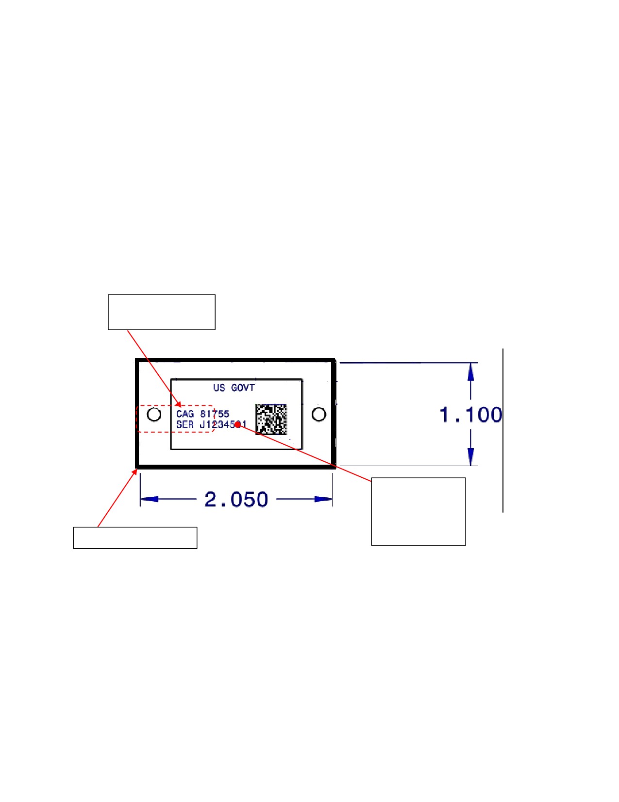
TMS-MC-015
Revision 30
Page 25 of 104
01 April 2016
3.12 When Tool Trial Run is required for tools which have associated equipment (example: portable power
equipment), Tool Trial Run of the equipment is required also.
*4.0 TOOL IDENTIFICATION AND SHIPPING REQUIREMENTS - DELIVERABLE TOOLING
4.1 Tool identification for Buyer tooling is controlled by PM-4053. Seller shall check for the latest revision
of PM-4053 requirements by visiting the on-line revision history link located on the Buyer’s BTP website.
4.2 Seller shall identify each Seller-manufactured ST in a conspicuous place using a permanent method
such as stamping, engraving, etching, stenciling, etc., as required, per PM-4053.
**4.2.1 When imposed by PO, Seller shall identify tooling with applicable IUID marking per
PM-4053 Section 3.8. See example illustration below;
IUID Example:
Lockheed Martin
Provided
2-D data
matrix;
Incorporating
Format 12 “TEI”
DS957-2 Metal Frame
*4.3 To ensure applicable inspection data and acceptance reports remain with the tool once received at
Buyer’s facilities, Seller shall secure all technical, inspection and acceptance data reports in a sealed
envelope. The sealed envelope shall include the following note on the outside of the envelope: “These
documents to Remain with Tool - Do Not Remove”.
4.4 Seller shall package, preserve, and protect all tooling designated to be shipped overseas as directed in
this PO and PM-4053, section 3.16.
5.0 PROCESS FOR TRANSFERRING TOOL DESIGNS FROM SELLER TO BUYER
5.1 Digital Data Transfer - The transfer of digital data between Seller and Buyer is controlled through
Buyer’s BTP Computer Aided Design/Computer Aided Manufacturing (CAD/CAM) Engineering Data
TMS-MC-015
Revision 30
Page 26 of 104
01 April 2016
Transfer Group. Buyer shall identify Seller’s Points Of Contact (POC) for setup of digital data transfer
capabilities and forward this information to Buyer’s BTP CAD/CAM Engineering Data Transfer Group.
Buyer’s BTP CAD/CAM Engineering Data Transfer Group shall contact Seller’s POCs and identify required
capabilities, data transfer site information, (including passwords, directory information, email notifications,
and access controls), and how Seller will be notified of data transfer activities.
5.2 Hardcopy Data Transfer - Seller shall coordinate all hard copy transfer of designs through Buyer if
required by this PO.
6.0 SEALING CRITICAL LOCATORS
6.1 Torque seal requirements for sealing tooling locators are defined by site and program as follows:
Fort Worth requirements:
F-22A tooling - Pink
All other tooling - Purple
Marietta requirements:
All Programs Tooling - Pink
Palmdale requirements:
All Programs Tooling - Pink
All torque seal applications that are not for sealing locators or critical locating features can be
White.
*7.0 DUPLICATE TOOL MANUFACTURING
*7.1 Seller shall manufacture duplicates of Buyer’s tools, when authorized by Buyer, and shall verify that
the original Buyer tool matches the original tool design before proceeding with duplication task.
7.2 Seller shall notify Buyer if discrepancies exist between Tool and Tool Design as required in Part I,
section 2.13.
8.0 INTERCHANGEABLE-REPLACEABLE “I/R” DESIGN AND MANUFACTURING
8.1 Seller shall design and manufacture all tooling containing I/R features as defined in PM-4053.
8.2 Seller of Buyer authorized “design and build” tooling shall design I/R tools as illustrated in Figure 1 and
PM-4053 Section 2.4.
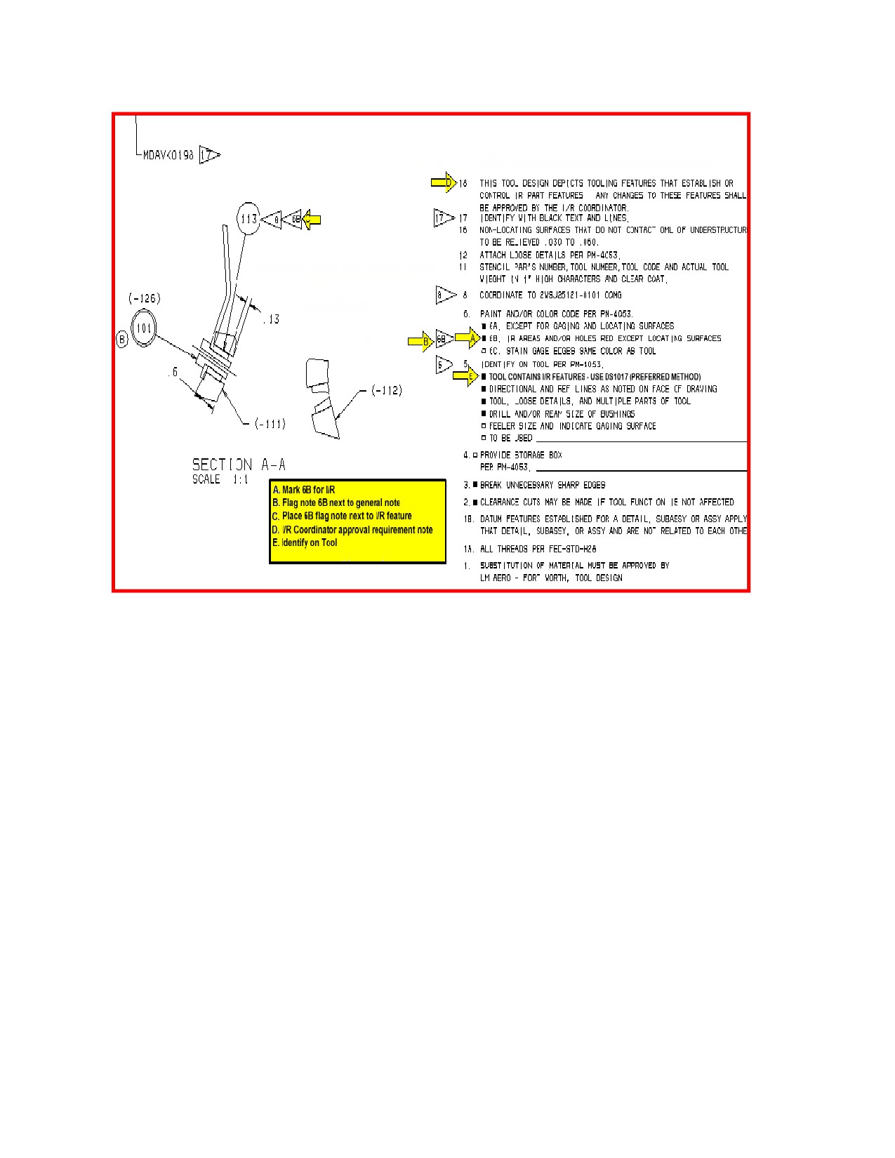
TMS-MC-015
Revision 30
Page 27 of 104
01 April 2016
Figure 1. I-R Tool Design Requirements
9.0 NON INTERCHEABLE OR REPLACEABLE (I/R), DESIGN AND MANUFACTURING
9.1 Seller shall receive written authorization to design and manufacture tools, once submittal of design,
sketch, drawing, concept or schematics have been approved by Buyer’s program personnel.
9.2 Seller shall notify Buyer’s Quality representative when written authorization has been received. Seller’s
Buyer Quality representative shall jointly develop an applicable validation process of all special processes,
critical dimensions, leak checks, or any unique point in the manufacturing process.
END PART II
TMS-MC-015
Revision 30
Page 28 of 104
01 April 2016
PART III
INTERNATIONAL SELLER REQUIREMENTS
1.0 GENERAL
1.1 Part III is applicable to programs in which Buyer furnishes Seller with items or material to support
Buyer’s BTP, and is in addition to the requirements of Part I and Part II of this manual.
*1.2 Fabrication requirements of ST, STE, and MKT by Seller or Seller’s sub-tiers to produce Buyer-
designed items and aircraft modifications, as specifically contracted by this PO, are defined in Part II of this
Manual and controlled by PM-4053, Section 10.0.
2.0 CONTROL OF SE, MTE AND STE
2.1 Receipt of SE - Seller shall return a stamped copy of SE receiver to Buyer within five (5) working days
upon receipt of SE.
2.1.1 Maintenance and repair parts for SE - Seller shall requisition maintenance and repair parts
for the SE provided as MSE from Buyer.
2.1.2 Modification of SE provided as MSE peculiar modification of SE - Seller shall receive a tool
order, a peculiar modification kit and written Buyer authorization. Upon completion of modification,
Seller will return the stamped off / approved copy of the tool order to Buyer.
2.1.3 Time Compliance Tech Order “TCTO” modification of SE - Seller shall receive a TCTO
modification kit and written authorization from Buyer authorizing Seller to install the kit. Upon
completion of kit installation, Seller shall return a completed Letter of Certification “LOC” to Buyer.
2.2 Receipt of MTE - Seller shall acknowledge receipt of the CPL by signing and returning the original
CPL to Buyer.
2.2.1 Maintenance and Repair parts for MTE - Seller shall requisition maintenance and repair
parts for the MTE from Buyer.
2.2.2 Modification of MTE - Seller shall not perform modification on MTE without prior written
authorization from Buyer.
2.3 Receipt, Maintenance and Modification of STE other than MTE Receipt - Seller shall acknowledge
receipt of STE, if any, by signing and returning the original CPL to Buyer within five (5) working days after
receipt of STE.
2.3.1 Maintenance and Repair Parts - Seller shall requisition maintenance and repair parts for
STE from Buyer.
2.3.2 Modification - Seller shall not perform modification of STE without prior written authorization
and direction from Buyer.
2.4 Disposition of SE, MTE and STE - Seller shall request disposition instructions from Buyer when SE,
MTE, and STE become surplus or obsolete.
2.5 Seller shall verify condition of all ST, SE, STE, MTE, MSE and MKT upon receipt for damage and
contents and immediately inform Buyer and Buyer’s Quality Representative of any damage or missing
contents, e.g., loose details, designs, records or Forms.
TMS-MC-015
Revision 30
Page 29 of 104
01 April 2016
2.6 Seller shall notify Buyer’s Quality representative as illustrated in Part I, section 10.0 (Shipping and
Receiving Instructions) prior to receipt or shipment of any Buyer furnished tooling or equipment.
2.7 Seller shall Trial Run applicable ST as directed by this PO or as illustrated in Part II, section 3.0 of this
Manual. Buyer may elect to provide hard copies of applicable sections of PM-4053 or PM-9003, section
20.41 for specific instructions.
3.0 CHANGE AUTHORIZATION
3.1 Seller shall not rework, repair, or in any way alter control tools without prior Buyer written authorization
in this PO or in a SATR disposition with a revised CPL and tool drawings, if required, to rework or re-stamp
control tools per PM-4053, section 10.0.
*3.2 Seller shall return to Buyer the stamped and signed Tool Rework Form document and revised CPL
upon completion of Buyer authorized rework or repair per PM-4053, section 10.0.
*4.0 TOOLING PRACTICES FOR BUYER-FURNISHED TOOLS - Category “A” tools are control tools
that establish dimensions and features of production tools which control I/R or coordination points of other
production tools. Seller shall use these tools as Control Media only to fabricate production and inspection
tools. The following is a list of the affected tools:
COMG - Component Master Gage
FCGA - Facility Gage
MSFM/TOFM - Master Form/Tooling Form. For contour only. Lines on MSFM/TOFM are for
reference only and
Seller may revise or add these lines to satisfy their production tool requirements without prior
written authorization from Buyer.
MSGA - Master Gage
MSPE - Master Plate
PDSE - Production Samples (Tube)
TOGA - Tooling Gage
TOSE - Tooling Sample (Welded Tubes/Ducts)
Any tool identified by this PO and provided as a control tool
5.0 LISTINGS OF SELLER-FABRICATED/PROCURED ST OR STE
5.1 Seller shall establish and maintain a part list and tool list, by manufacturer’s part number, of ST or STE
fabricated or procured by Seller, as required by Buyer. Seller shall not include any Buyer-furnished ST or
STE in the list(s).
5.2 Seller shall produce and maintain listings of all tools required to fabricate Federal Identification Item
Number (FIIN) spare Items.
6.0 DRAWINGS, SKETCHES, TOOL DESIGNS, ETC.
6.1 Seller shall maintain Seller-owned or Buyer-furnished current tool designs, sketches, photographs, and
schematic drawings used in the fabrication, testing, or calibration of tooling. Seller shall provide a
disposition of this data at the same time disposition for related tooling is given, as requested by Buyer.
6.2 Seller shall ensure Seller’s STE drawings of any electrical, electronic, hydraulic or pneumatic type, at a
minimum, consist of a schematic with component parts called out by characteristics or part number,
including adequate calibration and operation instructions.
TMS-MC-015
Revision 30
Page 30 of 104
01 April 2016
7.0 CALIBRATION AND RE-CALIBRATION OF BUYER-FURNISHED OR SELLER-FABRICATED STE
7.1 Seller shall develop and maintain a schedule for maintaining calibration of Buyer-furnished or Seller-
fabricated STE. Seller’s schedule is subject to approval of Buyer’s representative and Seller shall ensure
such schedule includes the following:
Name and function of test equipment
Serial or identification number of test equipment
Criteria or standard to which test equipment is checked
Frequency of test
7.2 Buyer shall determine mode of transportation for STE and make arrangements for shipment, when
STE is required at another location.
8.0 TOOLING USE AND TOLERANCE REQUIRMENTS - Seller shall comply with the tool usage and
tolerance requirements as defined in PM-4053, unless unique requirements are otherwise specified on the
Statement of Work “SOW”, BTP, or this PO.
*9.0 QUALITY ASSURANCE REQUIREMENTS OF SELLER-OWNED OR SELLER-FABRICATED
PRODUCTION TOOLING
*9.1 Seller shall submit applicable data of all Seller-fabricated or Seller-owned production tooling to
Buyer’s Program Management for review and approval prior to release of tool for trial run or FAI. Such
data may include, but is not limited to, engineering data, drawings, designs, Master Layouts (MEL), etc. In
addition, Seller shall use data generated by Trial Run to satisfy Buyer’s FAI requirement, if witnessed by
Buyer’s Quality representative or designated alternate.
9.2 Seller shall inspect all Seller-fabricated production tooling, which has been manufactured utilizing
Buyer-furnished Control Media, by utilizing applicable tooling tolerances defined in PM-4053.
9.3 Seller shall inspect or re-verify subsequent parts produced utilizing Seller-fabricated production tooling
to the criteria defined in PM-4053.
9.4 Seller shall ensure each Item manufactured with Seller-fabricated ST and STE is identified in a
conspicuous place with the current part number and dash number, Tool Code, any peculiar tool number,
the “Also Use” current part number (if applicable), or Engineering Change Notice “ECN”. Seller shall
identify STE and MKT as “Property of USGOVT” and ST as “Property of Seller”, or as directed by this PO.
END OF PART III
TMS-MC-015
Revision 30
Page 31 of 104
01 April 2016
* REVISED
** ADDED
_____________________________________________________________________________
PART IV
APPENDICES
APPENDIX A - REWORK, REPAIR AND COORDINATION GUIDE
APPENDIX TABLE OF CONTENTS
1.0 SCOPE
2.0 TOOLING PRECEDENCE OVER ENGINEERING STATEMENTS
3.0 PRESERVATION OF BUYER FURNISHED TOOLS
4.0 STANDARD REPAIR TOLERANCES AND COORDINATION
5.0 STANDARD I/R IDENTIFICATION AND REWORK
6.0 “TO MATCH” HOLE PATTERNS AND OTHER I/R FEATURES
7.0 SHIPPING AND STORAGE CONTAINERS FOR BUYER FURNISHED TOOLS
8.0 BUYER FURNISHED TOOLING AND SELLER TO SELLER TRANSFER OF TOOLS
9.0 SET - UP PROCEDURE FOR FLOOR BASED ASSEMBLY JIGS
**************************************************************************************
*1.0 SCOPE
1.1 Appendix A is applicable for all programs at all sites and is included in this Manual as specification
guidance for the preservation, alter, rework, repair and coordination of Buyer-furnished tools when
authorized by PO, and to define applicability of Special Tooling for specific Legacy aircraft parts,
components, and assemblies.
*1.2 Appendix A is not all inclusive of tool maintenance, alter, rework, repair, and coordination
requirements. This Manual section is intended to be utilized in conjunction with the requirements set forth
in PM-4053 when applicable. If Seller does not have access to PM-4053, Buyer is authorized to furnish
hard copies of applicable sections for Seller’s use, only when necessary.
2.0 TOOLING PRECEDENCE OVER ENGINEERING STATEMENTS
2.1 References to PM-4053 within this section are provided herein for such use by Seller. Buyer may
furnish hard copies of applicable sections of PM-4053 or referenced Program Documents. Any hard copy
distribution shall be limited to and applicable to this PO only.
2.2 For C-130 and P-3 Programs, Control Tools shall define the nominal configuration for the features they
represent. In most cases, the C-130 and C-5 Programs manage configuration control of Interchangeable
and Replaceable (I-R) features by means of Master Control Tools. Upon manufacture and acceptance,
these Master Control Tools establish the master product definition and take precedence over the
Engineering Drawings for the features they represent. Production tooling produced and coordinated to
such Master Control Tooling serves as the primary means for creating and accepting controlled product
features. Reference PM-4053, section 3.1.3.5.
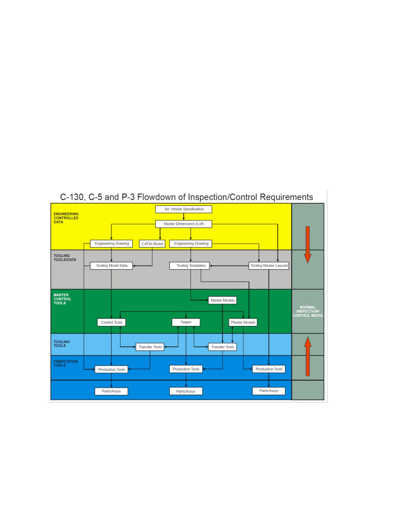
TMS-MC-015
Revision 30
Page 32 of 104
01 April 2016
2.3 “For C-130 and C-5 programs, the furnished Special (Project) Tools shall be considered the
Engineering definition of the features they control unless otherwise noted in this PO. Example of such tools
would be an ATT, STFB, DJ, etc. If through usage, rejection and subsequent investigation, any such tool
feature is found to produce results non-conforming to Engineering Drawing specifications, then the same
must be reviewed for corrective action as necessary, unless it is created by program Master Control
Tooling”. Reference PM-4053, section 3.1.3.5.
2.3.1 When a project tool is specified by this PO to control a feature of deliverable item(s) to
Buyer, the same tool shall be considered the Media of Acceptance for that feature and
configuration.
2.4 Order of Precedence for Manufacture of the P-3/CP-140 ASLEP Kit (LG05ER0167) provides direction
for the implementation and management of variation between Engineering Drawings and Tooling (Control
Media) for the P-3/CP-140 aircraft. Specifically, this document provides direction for policies and
processes to resolve dimensional conflicts between Engineering Drawings and accountable Special
(Project) Tools for all P-3 and P-3 derivative programs, including CP-140. This document is applicable to
P-3/CP-140 ASLEP kit manufacturing at all LM Aero facilities and suppliers. Reference PM-4053, section
3.1.3.6.
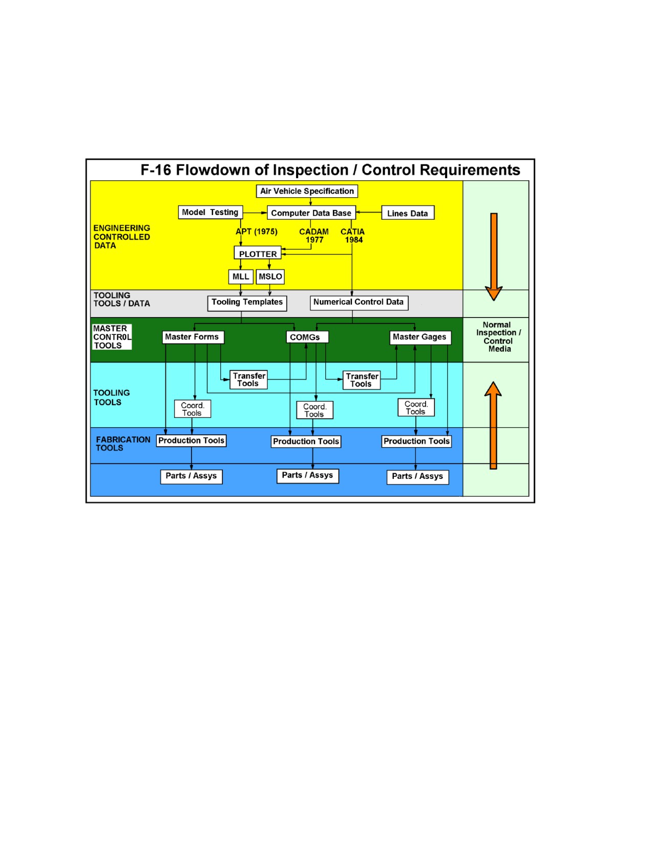
TMS-MC-015
Revision 30
Page 33 of 104
01 April 2016
2.5 Order of Precedence for Control Media for Manufacturing of the F-16 (16PP1957) defines the
traceability established from released engineering design to the completed aircraft for the F-16 Program. In
addition to describing this process, this document provides the policy and guidance for continued
inspection to tooling media and continued corrective action wherein exterior and interior lines and surfaces
of components of the aircraft are involved.

TMS-MC-015
Revision 30
Page 34 of 104
01 April 2016
2.6 Order of Precedence for Control Media for Manufacture of the F-22. See document number
5PD41327, which defines the Order of Precedence to be utilized for control, acceptance, and corrective
actions of F-22 designs, tooling, and parts.
//////////////////////