FANUC DAEWOO CNC PROGRAM MANUAL - page 4
TRAINING
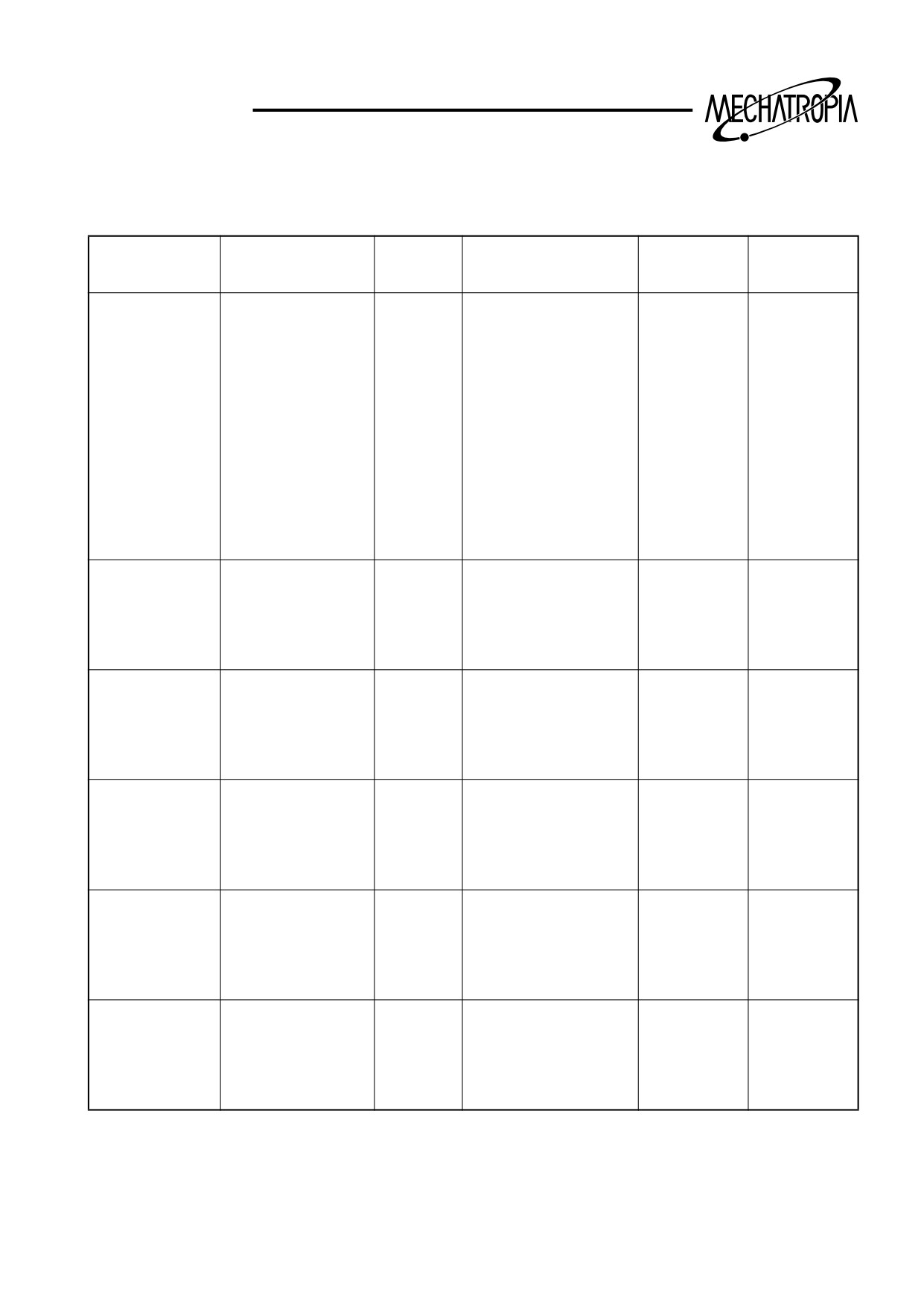
Cutting condition
1. Cutting condition
Depth of cutting
Cutting speed
Feedrate
Material
Classification
Material of tool
d(mm)
v (m/min)
F (mm/rev.)
Carbon steel
Stock vemoval
3 ~ 5
180 ~ 200
0.3 ~ 0.4
P 10 ~ 20
60kg/mm
2 ~ 3
200 ~ 250
0.3 ~ 0.4
P 10 ~ 20
(Tensile
strength)
Finishing
0.2 ~ 0.5
250 ~ 280
0.1 ~ 0.2
P 01 ~ 10
Thread
124 ~ 125
P 10 ~ 20
Grooving
90 ~ 110
0.08 ~ 0.2
P 10 ~ 20
Center drill
1000 ~ 1600 rpm
0.08 ~ 0.15
SKH 2
Drill
~ 25
0.08 ~ 0.2
SKH9
Alloy steel
Stock removal
3 ~ 4
150 ~ 180
0.3 ~ 0.4
P10 ~ 20
140kg/mm2
Finishing
0.2 ~ 0.5
200 ~ 250
0.1 ~ 0.2
P 10 ~ 20
Grooving
70 ~ 100
0.08 ~ 0.2
P 10 ~ 20
Castiron
Stock removal
3 ~ 4
200 ~ 250
0.3 ~ 0.5
K 10 ~ 20
HB 150
Finishing
0.2 ~ 0.5
250 ~ 280
0.1 ~ 0.2
K 10 ~ 20
Grooving
100 ~ 125
0.08 ~ 0.2
K 10 ~ 20
Aluminum
Stock removal
2 ~ 4
400 ~ 1000
0.3 ~ 0.5
K 10
Finishing
0.2 ~ 0.5
700 ~ 1600
0.1 ~ 0.2
K 10
Grooving
350 ~ 1000
0.1 ~ 0.2
K 10
Bronge
Stock removal
3 ~ 5
150 ~ 300
0.2 ~ 0.4
K 10
Brass
Finishing
0.2 ~ 0.5
200 ~ 500
0.1 ~ 0.2
K 10
Grooving
150 ~ 200
0.1 ~ 0.2
K 10
Staialess steel
Stock removal
2 ~ 3
150 ~ 180
0.2 ~ 0.35
P 10 ~ 20
Finishing
0.2 ~ 0.5
180 ~ 200
0.1 ~ 0.2
P 01 ~ 10
Grooving
60 ~ 90
~ 0.15
P 10 ~ 20
(Note) 1) Conditions for tools coated
2) Cutting condition shall be changed by the shape and angle of tools
89
TRAINING
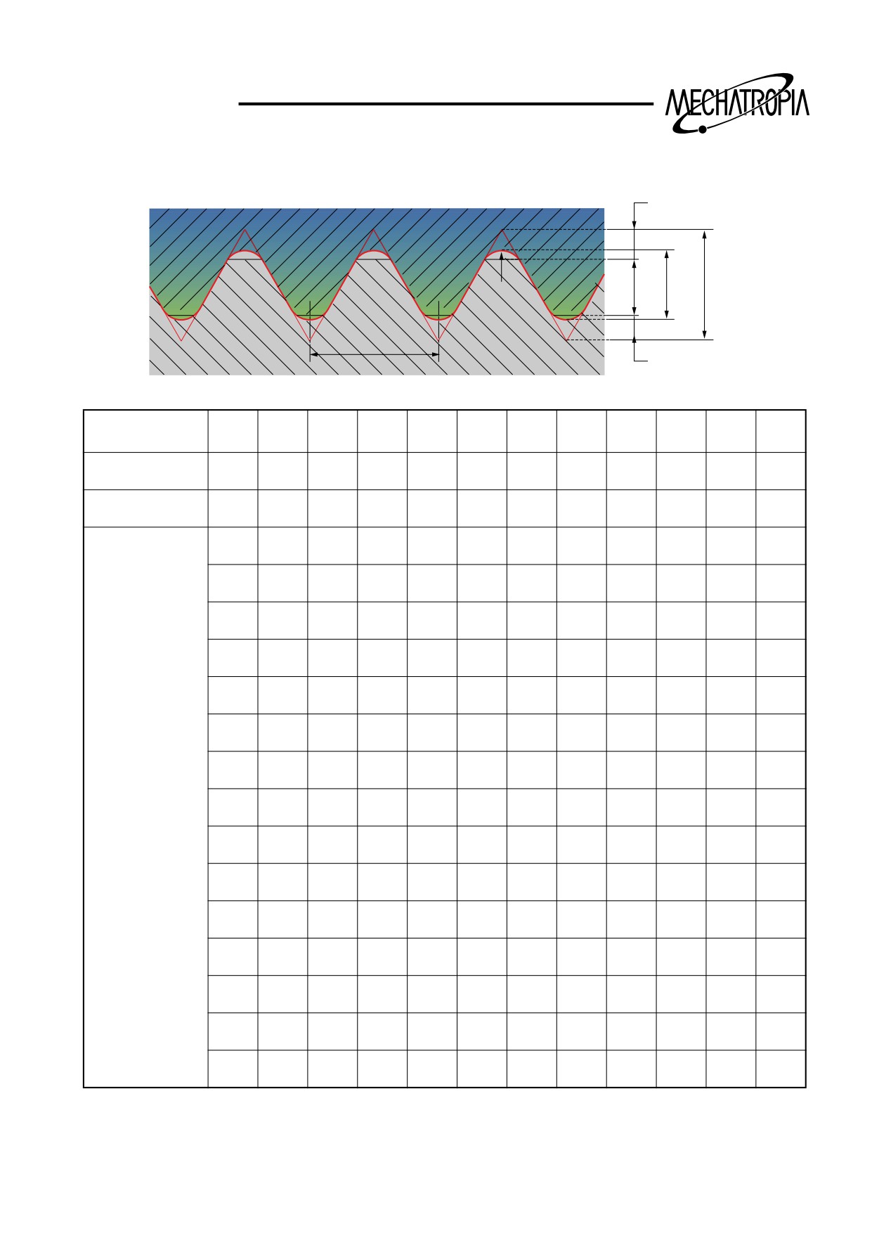
2. Cutting time of thread process(For thread precessing with the S 45 C)
H/8
0.072P
H1
H2
H
R
P
H/4
PITCH
P1.0
1.0
1.25
1.5
1.75
2.0
2.5
3.0
3.5
4.0
4.5
5.0
CUTTING DEPT
H2
0.6
0.74
0.89
1.05
1.19
1.49
1.79
2.08
2.38
2.68
2.98
CORNER ROUND
R
0.07
0.09
0.11
0.13
0.14
0.18
0.22
0.25
0.29
0.32
0.36
1
0.25
0.30
0.30
0.30
0.30
0.30
0.35
0.35
0.35
0.40
0.45
2
0.20
0.20
0.20
0.25
0.25
0.28
0.30
0.35
0.35
0.35
0.35
3
0.10
0.11
0.14
0.16
0.20
0.24
0.26
0.30
0.30
0.30
0.32
4
0.05
0.08
0.12
0.12
0.14
0.20
0.22
0.25
0.26
0.28
0.30
5
0.05
0.08
0.10
0.11
0.15
0.18
0.20
0.23
0.25
0.25
6
0.05
0.07
0.08
0.11
0.13
0.15
0.20
0.22
0.25
SCREW
7
0.05
0.06
0.09
0.10
0.12
0.17
0.20
0.20
CUTTING
8
0.05
0.07
0.08
0.10
0.14
0.15
0.17
NUMBER OF
9
0.05
0.07
0.08
0.10
0.12
0.15
TIMES
10
0.05
0.05
0.10
0.10
0.15
11
0.05
0.05
0.08
0.08
0.10
12
0.05
0.05
0.08
0.10
13
0.05
0.05
0.08
14
0.05
0.06
15
0.05
0.06
90
TRAINING
+X
-Z
+Z
M
W
WORK SHIFT VALUE
-X
7
8
9
RESET
ALTER
OFFSET / GEOMETRY
O1000
N0000
O
N
G
NO.
X
Z
T
R
G 01
10.000
1.000
0.000
0
4
5
6
X
Y
Z
INSRT
G 02
1.486
-49.561
0.000
0
CURSOR
G 03
1.486
-49.561
0.000
0
1
2
3
G 04
0.000
0.000
0.000
0
H
F
R
DELET
G 05
1.486
-49.561
0.000
0
G 06
1.486
-49.561
0.000
0
-
0
/
#
M
S
T
EOB
G 07
1.486
-49.561
0.000
0
G 08
1.486
-49.561
K
4t h
Q
J
NO.
CAN
ACT. POSITION(RELATIVE)
B
I
P
U
0.000
W
0.000
PAGE
NUM.
MZ
120.
S
MDI
0T
MENU
POS
PRGRM
INPUT
OFSET
WEAR
GEOM
W.SHIFT
MRCRO
DGNOS
OPR
AUX
OUTPT
PARAM
ALARM
GRAPH
START
91
TRAINING
7
8
9
RESET
ALTER
O
N
G
WORK SHIFT
4
5
6
(SHIFT VALVE)
X
Y
Z
INSRT
CURSOR
X
0.000
1
2
3
Z
23.061
DELET
H
F
R
-
0
/
#
ACT. POSITION(RELATIVE)
M
S
T
EOB
U
0.000
4t h
K
Q
J
NO.
CAN
B
I
P
ADRS.
PAGE
MDI
POS
PRGRM
MENU
INPUT
OFSET
WEAR
GEOM
W.SHIFT
MRCRO
DGNOS
OPR
AUX
OUTPT
PARAM
ALARM
GRAPH
START
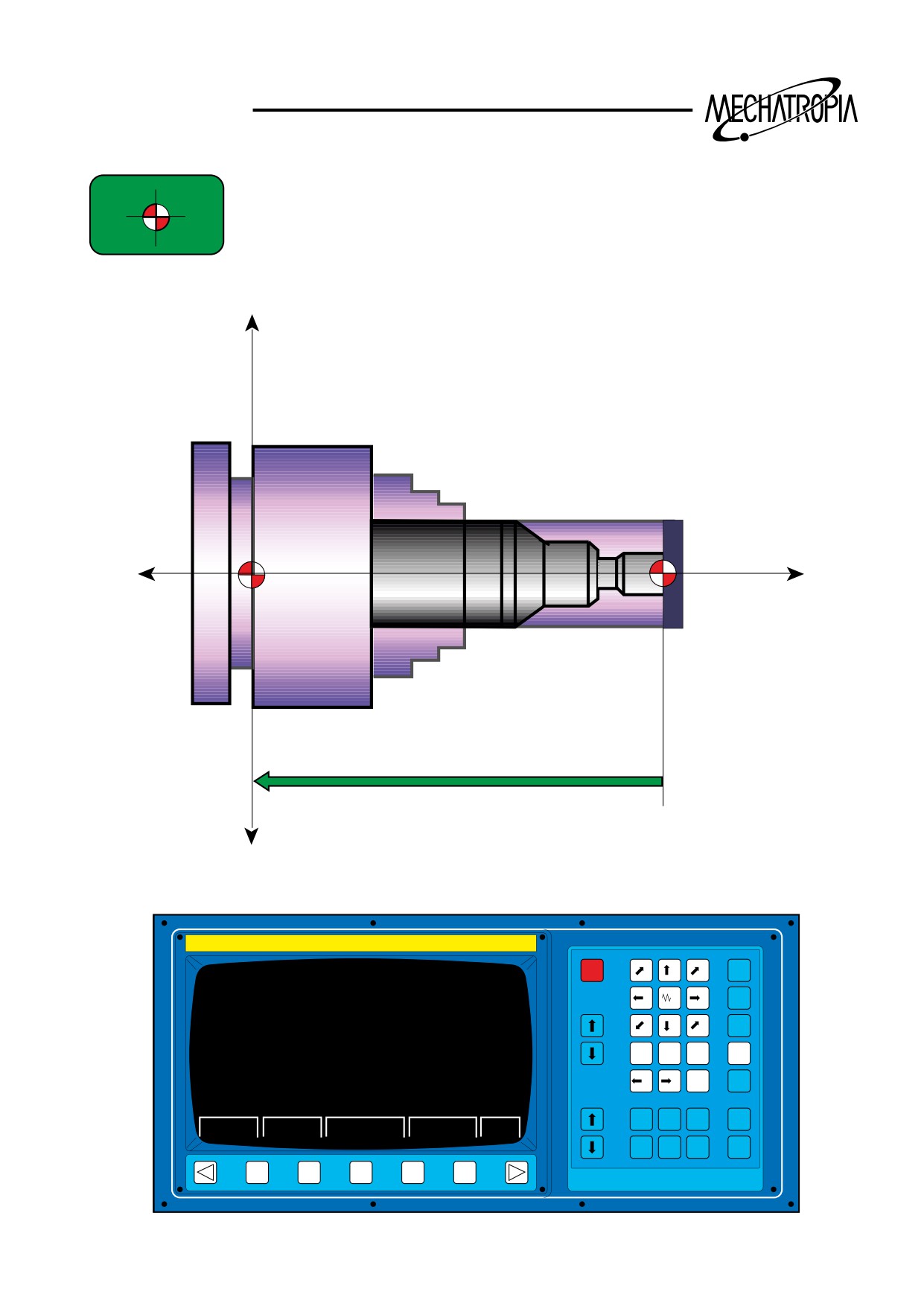
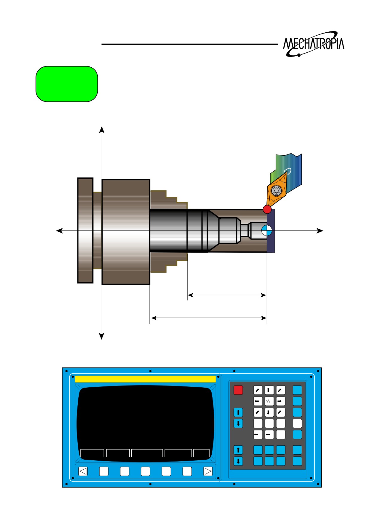
Work shift method using the tool measure
1.Return to the reference manually.
2. Install the work piece to the JAW and move the TURRET to appropriate position, and then pre-
pare the basic tools to work.
3. On the section of material, TOUCH of process in facing the basic tool
∴At this, it is absolutely not allowed to move the Z spindle.
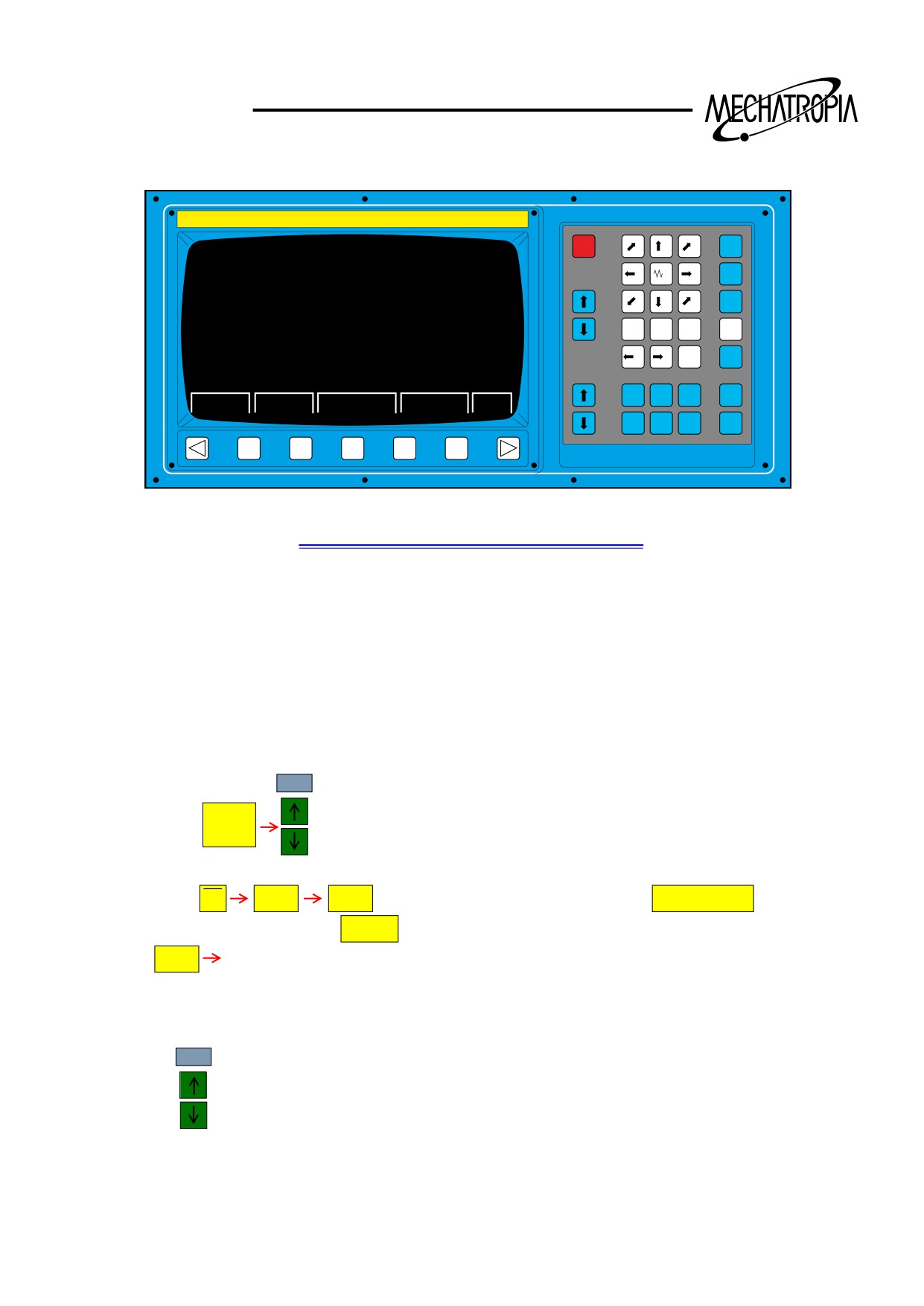
4. Select WORK/SHIFT screen.
PAGE
Method)
MENU
Push the bottun to select the WORK/SHIFT
OFSET
5. Inpit the DATA.
5
Method) M
W
DATA
push bottuns one by one, and push
MEASURE
on the
Z
console, and push INPUT
, then identify the input.
∗ DATA
Z coordinate value in the program (Touched position)
∗ After input, Z value on the screen of WORK/SHIFT is automatically calculated and input.
6. As the input is completed,
PAGE
Push
to select the OFFSET screen.
92
TRAINING
Offs.
+X
-Z
+Z
60
80
-X
7
8
9
RESET
ALTER
OFFSET / GEOMETRY
O1000
N0000
O
N
G
NO.
X
Z
T
R
G 01
10.000
1.000
0.000
0
4
5
6
X
Y
Z
INSRT
G 02
1.486
-49.561
0.000
0
CURSOR
G 03
1.486
-49.561
0.000
0
1
2
3
G 04
0.000
0.000
0.000
0
H
F
R
DELET
G 05
1.486
-49.561
0.000
0
G 06
1.486
-49.561
0.000
0
-
0
/
#
M
S
T
EOB
G 07
1.486
-49.561
0.000
0
G 08
1.486
-49.561
K
4t h
Q
J
NO.
CAN
ACT. POSITION(RELATIVE)
B
I
P
U
0.000
W
0.000
PAGE
NUM.
MZ
120.
S
MDI
0T
MENU
POS
PRGRM
INPUT
OFSET
WEAR
GEOM
W.SHIFT
MRCRO
DGNOS
OPR
AUX
OUTPT
PARAM
ALARM
GRAPH
START
93
TRAINING
7
8
9
RESET
ALTER
OFFSET / GEOMETRY
O1000
N0000
O
N
G
NO.
X
Z
T
R
4
5
6
G 01
0.000
0.000
0.000
0
INSRT
X
Y
Z
G 02
0.000
0.000
0.000
0
CURSOR
G 03
0.000
0.000
0.000
0
1
2
3
DELET
G 04
0.000
0.000
0.000
0
H
F
R
G 05
0.000
0.000
0.000
0
G 06
0.000
0.000
0.000
0
-
0
/
#
M
S
T
EOB
G 07
0.000
0.000
0.000
0
4t h
K
Q
J
NO.
CAN
ACT. POSITION(RELATIVE)
B
I
P
U
0.000
W
0.000
PAGE
NUM.
MZ
120.
S
MDI
0T
MENU
POS
PRGRM
INPUT
OFSET
WEAR
GEOM
W.SHIFT
MRCRO
DGNOS
OPR
AUX
OUTPT
PARAM
ALARM
GRAPH
START
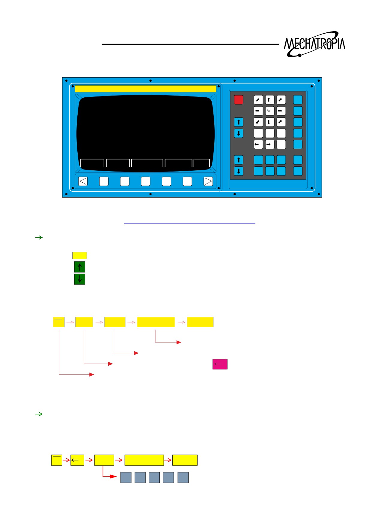
OFFSET method using Tool measure
Z axis OFFSET
1. After selecting OFFSET screen
CURSOR
push
to move the OFFSET No. of the basic tool .
∗ In gereral, tool no. and OFFSET No. shall be the same
2. After selecting numbers, input the coordinate value of Z in the current position which is touched.
The method shall be the same as work shift. For summary,
5
M
W
Z
DATA
MEASURE
INPUT
Located in the console
Touched currend position is the Z coordinate value in the program.
4
Select Z axis. In case of X axis,
should be pushed.
X
Indicates the initial “M” of measure.
After input as above, Z value of OFFSET selected by the cursor is automatically input, but the
basic tool becomes “ 0 ”(zero). If another value is given, start from the begining again.(Work shift
end)
X axis OFFSET
3. Continuously, process the outside diameter with the basic tool, and retreat the Z spindle to +
direction(right hand), stop rotating, then measure the processed outside diameter(Xvalue). If the
measured value is ø52.34, the position of tool is X52.34 therefor, input the X value.
5
DATA
MEASURE
INPUT
M
Z
5
2
¡⁄
3
4
94
TRAINING
∗ As you input with above method, X value on OFFSET screen is automatically input.
4. prepare another tool which you want to OFFSET to the work position.
5. Touch slightly on the section of the material.
6. If you input with the same method as finding the OFFSET value of Z spindle written previously, Z
OFFSET value of this tool is autonatically input. (Difference of length compared with the basic
tool)
7. Find the X OFFSET value with the same method as 3.
8. For all other tools, OFFSET with repeating above method(1~3).
(Attention)
1. On WORK/SHIFT screen, input only Z value, not X value.
(∗ Except the GANG TYPE)
2. For the drill and a kind of center drill, input only the OFFSET of Z spindle, leave the X value as
“ 0 ”.
3. Above explanation to find the value of OFFSET is the method when input only the Z value on
WORK/SHIFT screen.
If you input the X axis with the Z axis on WORK/SHIFT screen, you should input the OFFSET
value of X spindle for all tools which are processed in the center of main spindle like the drill
and the center drill.
5. If you OFFSET with above method with using the function of tool measure, you don,t have to
designate the coordinate as G50 during the programming.
Example)
(When using TOOL MEASURE)
O 3333 :
N1 G50 T0100 S1800 M42 :
G96 S100 M03 :
(When not using TOOL MEASURE)
O 3334 :
N1 G50 T100. Z100. T0100 S1800 M42 :
G96 S170 M03 :
95
TRAINING
M-FUNCTION
M00 : PROGRAM STOP
When M00 is commanded in automatic operation mode(MDI or MEM mode), the automatic oper-
ation will stop after completion of the command in the block containing M00.
When the machine is stopped by M00 code. Manual operation can be done if the mode selector
switch is turned to JOG position.
To restart cycle, select the mode selector switch to previous automatic operation mode and then
depress the CYCLE START button.
NOTE1)
Spindle stops after completion of M00, then chuck open-close can be done by manual without
changing the MODE.
M01 : OPTIONAL STOP
This command is used to stop the machine temporarily by slash(/) and check workpiece at the
end of each tool operations. OPTIONAL STOP switch(toggle switch) is used to selection this
code.
M02 : END OF PROGRAM
This code is used in the last block of chucking work part program to end the program.
When this code occurs during the automatic operation of the machine, the program returns to
the head after performing the other command in the block, the control is reset, this automatic
mode ends and the machine stop.
M03 : MAIN-SPINDLE FORWARD DIRECTION
Specifies to start the main spindle rotation in counterclockwise direction. S code should be spec-
ified in the same block or previous.
If M03 code is specified when the chuck is open, the sequence error will occur.
M04 : MAIN-SPINDLE REVERSE DIRECTION
Specifies to start the main spindle rotation in clockwise direction. S code should be specified in
the same block or previous.
If M04 code is specified when the chuck is open, the sequence error will occur.
M05 : MAIN-SPINDLE STOP
Specifies to stop the main spindle rotation. Even M05 is specified, the command spindle speed
remains effective. Therefore, if M03 or M04 is specified again, the spindle will rotate by the same
speed as the previous speed.
M07 : HIGH PRESSURE COOLANT ON (optional)
Specifies to start the high pressure coolant pump.
M08 : COOLANT ON
Specifies to start the coolant pump. The coolant pump will start when the COOLANT switch on
the operating panel is set to ON position.
M09 : COOLANT OFF
Specifies to stop the high pressure coolant pump and coolant pump.
M10: PART CATCHER1 ADVANCE (optional)
This command moves the part catcher1 advance.
96
TRAINING
M11 : PART CATCHER1 RETRACT (optional)
This command moves the part catcher1 retract.
M13 : AIR BLOW FOR TURRET (optional)
Air blow for turret when M13 is commanded.
M14 : AIR BLOW FOR MAIN SPINDLE (optional)
Air blow for main spindle when M14 is commanded.
M15 : AIR BLOW OFF (optional)
Air blowing stops.
This command is available on M13, M14.
M17 : MACHINE LOCK ON
Specifies to machine lock on. This command is specified only MDI mode.
M18 : MACHINE LOCK OFF
Specifies to machine lock off. This command is specified only MDI mode.
M19 : MAIN- SPINDLE ORIENTATION (optional)
This code stops main-spindle at fixed angle.
M19 Sxxx : Main-spindle multi orientation (ORIENTATION “B”)
When M19 code and S code should be specified in the same block, the spindle stops position is
determined by S code.
M24 : CHIP CONVEYOR RUN (optional)
Specifies to run the chip conveyor.
M25 : CHIP CONVEYOR STOP (optional)
Specifies to stop the chip conveyor.
M30 : PROGRAM END & REWIND (continuous running)
Return to head of the memory by M30 command, reset and stop.
The program is restarted by cycle start and specifies at last block.
M31: INTERLOCK BY-PASS (MAIN-SPINDLE & TAILSTOCK)
This code is used when cycle start is available the spindle unclamp and the tail stock quill opera-
tion during spindle rotating
M32 : STEADY REST CLAMP/UNCLAMP DURING SPINDLE ROTATION
This code is interlock by-pass of spindle rotating when STEADY REST is used.
STEASY REST clamp(M38 or M58) and unclamp(M39 & M59) is valid during spindle rotating
with M66.
M33 : REVOLVING TOOL-SPINDLE FORWARD DIRECTION
Revolving tool-spindle starts forward rotation.
M34 : REVOLVING TOOL-SPINDLE REVERSE DIRECTION
Revolving tool-spindle starts reverse rotation.
M35 : REVOLVING TOOL STOP
Revolving tool-spindle stops.
97
TRAINING
M38 : STEADY REST CLAMP(optional-right side), M58 : STEADY REST CLAMP(optional-left side)
Specifies to clamp the steady rest.
M39 : STEADY REST CLAMP(optional-right side), M59 : STEADY REST CLAMP(optional-left side)
Specifies to unclamp the steady rest.
M40 : GEAR CHANGE NEUTRAL
M41 : GEAR CHANGE LOW
M42 : GEAR CHANGE MIDDLE
M43 : GEAR CHANGE HIGH
Specifies to change the each gear range.
M46 : Prog. TAIL STOCK BODY UNCLAMP & TRACTION BAR ADVANCE (optional)
Simultaneous start of prog. Tail stock body unclamp and traction bar retract with this
command.
M47 : Prog. TAILSTOCK BODY CLAMP & TRACTION BAR RETRACT (optional)
Simultaneous start of prog. Tail stock body clamp and traction bar advance with this
command.
M50 : BAR FEEDING (optional)
When automatic bar feeder is attached, feed of material is performed.
M52 : SPLASH GUARD DOOR OPEN (optional)
The splash guard is opened with this command.
M53: SPLASH GUARD DOOR CLOSE (optional)
The splash guard is closed with this command.
M54 : PARTS COUNT (optional)
When M54 is commanded, pieces counter.
M61 : SWITCHING LOW SPEED (only aP60)
When the aP60 spindle motor is use, output torque and speed range of spindle is differ-
ence by power line switching. M61 is used to low speed rpm(Y-CONNECTION). 400 ˜
500 rpm(18.5kw)
M62 : SWITCHING HIGH SPEED (only aP60)
M62 is used to high speed rpm(
-CONNECTION). 750 ˜ 4500 rpm(22kw)
M63 : MAIN-SPINDLE CW & COOLANT ON
Simultaneous start of main-spindle forward rotation and coolant.
Spindle forward and coolant are preformed by one(M63) command. Coolant comes out
only when operation panel switch is “on”.
M64 : MAIN-SPINDLE CCW & COOLANT ON
Simultaneous start of main-spindle reverse rotation and coolant.
Spindle reverse and coolant are preformed by one(M64) command. Coolant comes out
only when operation panel switch is “on”.
98
TRAINING
M65 : MAIN-SPINDLE & COOLANT STOP
Stop of main-spindle rotation, coolant is stopped by one command.
M66 : DUAL CHUCKING LOW CLAMP (optional)
Main-chuck is closed by low pressure.
M67 : DUAL CHUCKING HIGH CLAMP (optional)
Main-chuck is closed by high pressure.
M68 : MAIN-SPINDLE CLAMP
Specified to open the main-chuck automatically such as bar work.
M69 : MAIN-SPINDLE UNCLAMP
Specified to close the main-chuck automatically such as bar work.
M70 : DUAL TAILSTOCK LOW ADVANCE (optional)
Tailstock bar is advanced by low pressure.
M74 : ERROR DETECT ON
When M74 is in effect, the control proceed to the next block regardless of the pulse lag of
servo between block for liner and circular interpolation except positioning (G00).
The permits the machine to move smoothly between blocks.
However, the corner of the workpiece may not be quite sharp.
M74 command is modal, and it will remain effective until M75 is command.
M75 : ERROR DETECT OFF
Specifies to release the state of error detection ON. When the power is turned on, M75
will be in effect, and it will remain effective until M74 is command.
M76 : CHAMFERING ON
When M76 is specified before the command of thread cutting cycle G76 or G92, the
threading tool will pull out at the terminating thread portion.
M77 : CHAMFERING OFF
Cancel the command of pull out threading function which as specified by M77 code.
M77 code is the modal code.
M78 : TAIL STOCK QUILL ADVANCE
The tail stock quill is advanced with this command.
M79 : TAIL STOCK QUILL RETRACT
The tail stock quill is retracted with this command.
M80 : QUICK-SETTER SWING ARM DOWN (optional)
Specifies to up the quick-setter swing arm.
M81 : QUICK-SETTER SWING ARM UP (optional)
Specifies to up the quick-setter swing arm.
99
TRAINING
M82 : MIRROR IMAGE ON
Specifies to mirror image on.
M83 : MIRROR IMAGE OFF
Specifies to mirror image off.
M84 : TURRET CW ROTATION
This code is used to switch the direction of turret indexing to CW when it is set in the
automatic selection mode.
As this code is as non-modal code, it should be used in the same block the T-code.
M85 : TURRET CCW ROTATION
The turret indexes in clockwise by specifying M85 in the same block of T-code.
This M85 is a non-modal code.
M86 : TORQUE SKIP ACT
This code is used to skip the torque of moving axis.
As this code is a modal code until M87 command, only valid the sub-spindle with B-axis.
EX) G00 B-500.0 ;
M86 ;
G98 G31 P99 V-20.0 F100.0 ;
G01 B-500.0 ;
M87 ;
M87 : TORQUE SKIP CANCEL
This code is used to cancel torque skip function of M86.
M88 : C-AXIS LOW CLAMP
Specified to clamp the C-axis by low pressure.
Only valid the C-axis control.
M89 : C-AXIS HIGH CLAMP
Specified to clamp the C-axis by high pressure.
Only valid the C-axis control.
M90 : C-AXIS UNCLAMP
Specified to unclamp the C-axis.
Only valid the C-axis control.
M91,M92,M93,M94 : EXTERNAL M-CODE COMMAND (optional)
There code spare M code.
M98 : SUB-Prog. CALL
This code is used to enter a sub-program.
M99 : END OF SUB-PROGRAM
This code shows the end of a sub-program.
Executing M99 take the control back to the main program.
100
TRAINING
M103 : SUB-SPINDLE FORWARD DIRECTION
Specifies to start the sub spindle rotation in counterclockwise direction. S code should
be specified in the same block or previous.
If M103 code is specified when the sub-chuck is open, the sequence error will occur.
M104 : SUB-SPINDLE REVERSE DIRECTION
Specifies to start the sub spindle rotation in clockwise direction. S code should be speci-
fied in the same block or previous.
If M04 code is specified when the sub-chuck is open, the sequence error will occur.
M105 : SUB-SPINDLE STOP
Specifies to stop the sub spindle rotation. Even M05 is specified, the command spindle
speed remains effective. Therefore, if M103 or M104 is specified again, the spindle will
rotate by the same speed as the previous speed.
M110 : PART CATCHER2 ADVANCE (optional)
This command moves the part catcher2 advance.
M111 : PART CATCHER2 RETRACT (optional)
This command moves the part catcher2 retract.
M114 : AIR BLOW FOR SUB SPINDLE (optional)
Air blow for sub spindle when M114 is commanded.
M119 : SUB-SPINDLE ORIENTATION (optional)
This code stops sub-spindle at fixed angle.
M119 Sxxx : sub-spindle multi orientation (ORIENTATION “B”)
When M19 code and S code should be specified in the same block, the spindle tops
position is determined by S code.
M131 : INTERLOCK BY-PASS (SUB-SPINDLE)
This code is used when cycle start valid on sub spindle unclamp.
M163 : SUB-SPINDLE CW & COOLANT ON
Simultaneous start of sub spindle forward rotation and coolant.
Spindle forward and coolant are preformed by one(M163) command. Coolant comes out
only when operation panel switch is “on”.
M164 : SUB-SPINDLE CW & COOLANT ON
Simultaneous start of sub spindle forward rotation and coolant.
Spindle forward and coolant are preformed by one(M164) command. Coolant comes out
only when operation panel switch is “on”.
M165 : SUB-SPINDLE & COOLANT STOP
The sub spindle rotation & coolant is stopped by one command.
M168 : SUB-SPINDLE CLAMP
Specifies to open the sub-chuck automatically such as bar work.
101
TRAINING
M169 : SUB-SPINDLE UNCLAMP
Specified to close the sub-chuck automatically such as bar work.
M203 : FORWARD SYNCHRONOUS COMMAND
Main and sub spindle start simultaneously for forward rotation.
It is synchronized with forward rotation of main and sub spindle.
M204 : REVERSE SYNCHRONOUS COMMAND
Main and sub spindle start simultaneously for reverse rotation.
It is synchronized with reverse rotation of main and sub spindle.
M205 : SYNCHRONOUS STOP
The synchronous rotation of main and sub spindle is stop.
M206 : SPINDLE ROTATION RELEASE
Specified to release the speed control of main and sub spindle.
If you want to the main and sub spindle is rotate by difference rpm, M206 is commanded before
S-code. Spindle override on operating panel valid last selected spindle.
EX) M03 S1000 ;
M206 ;
M103 S500 ;
102