FANUC DAEWOO CNC PROGRAM MANUAL - page 2
TRAINING
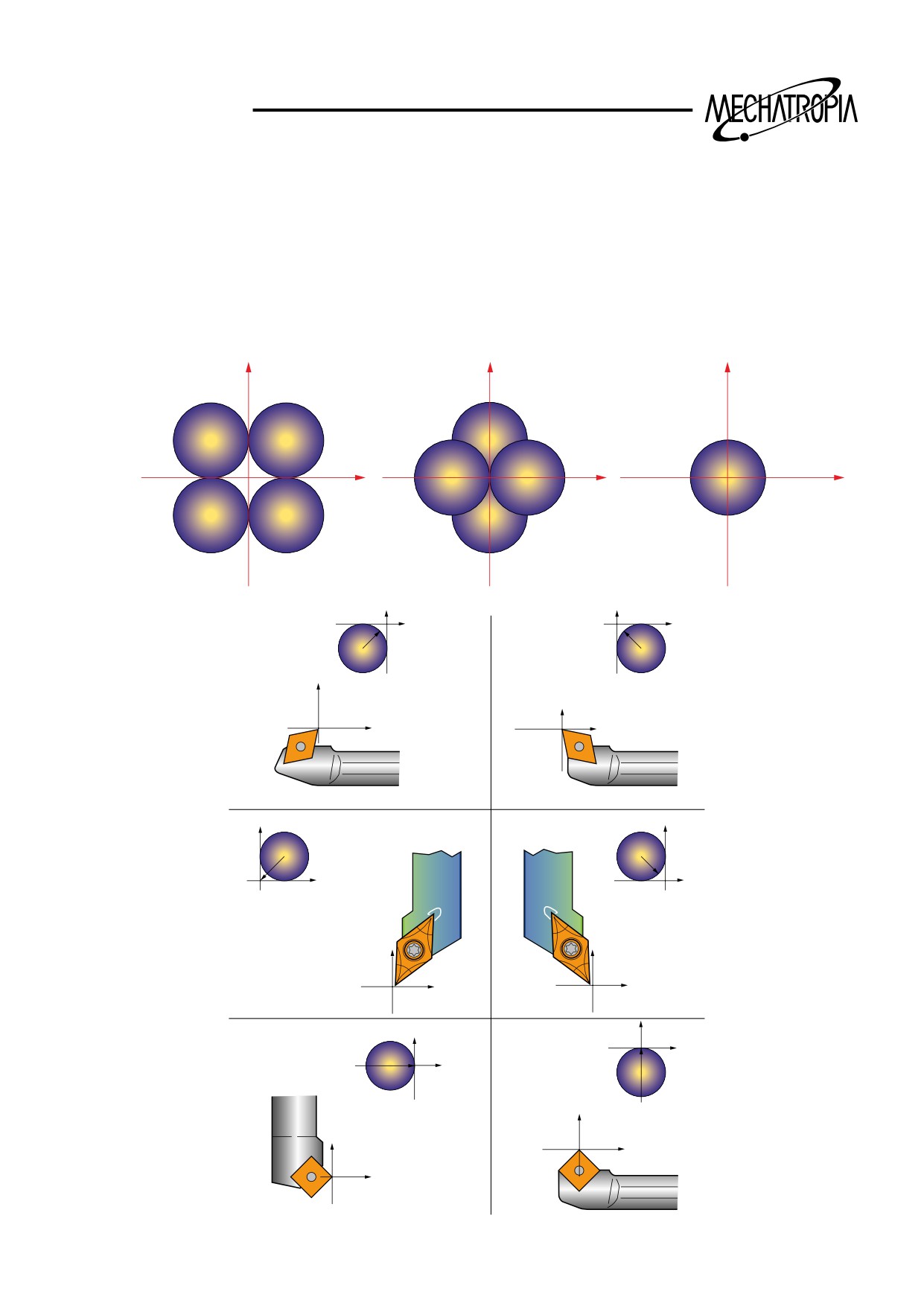
1) Direction of imaginary (In case of right hand coordinate)
Direction of imaginary seen from the center of radius is decided by the cutting direction of tool
during the cutting. Therefor, it should be set as much as compensation volume.
Direction and number of imaginary are decided among the following eight
types.
X
X
X
4
3
8
Z
Z
Z
5
7
9
1
2
6
<Selecting example of imaginary number>
1
2
3
4
5
6
29
TRAINING
8
7
9
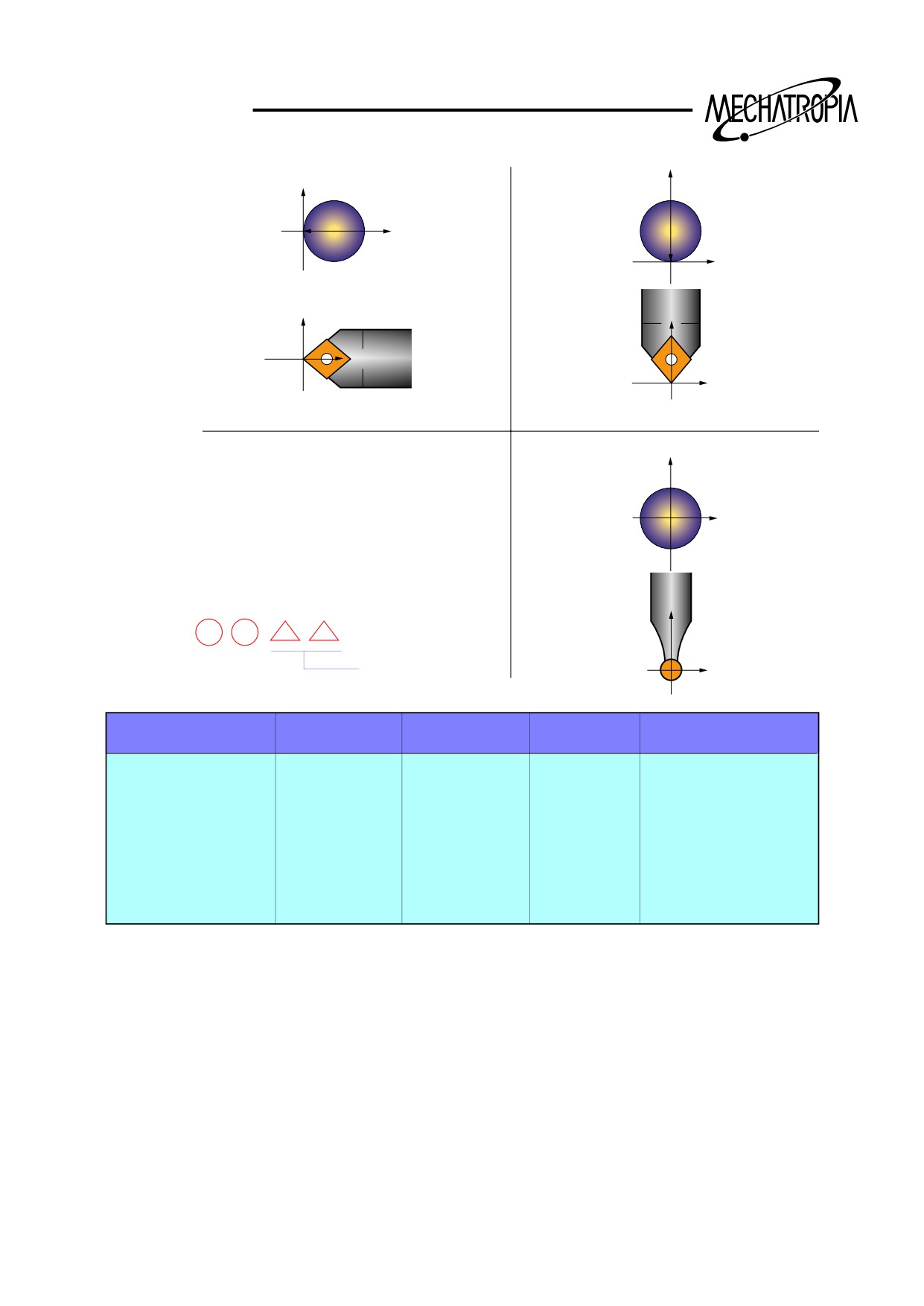
2) Compensation setting of
X
T
OFFSET No.
Z
OFFSETNO.
X
Z
TOOL DIRECTION
01
0.75
-0.93
0.4
3
0.2
-1.234
10.987
0.8
2
16
Command scope of OFFSET volume0- + 999.999mm
30
TRAINING
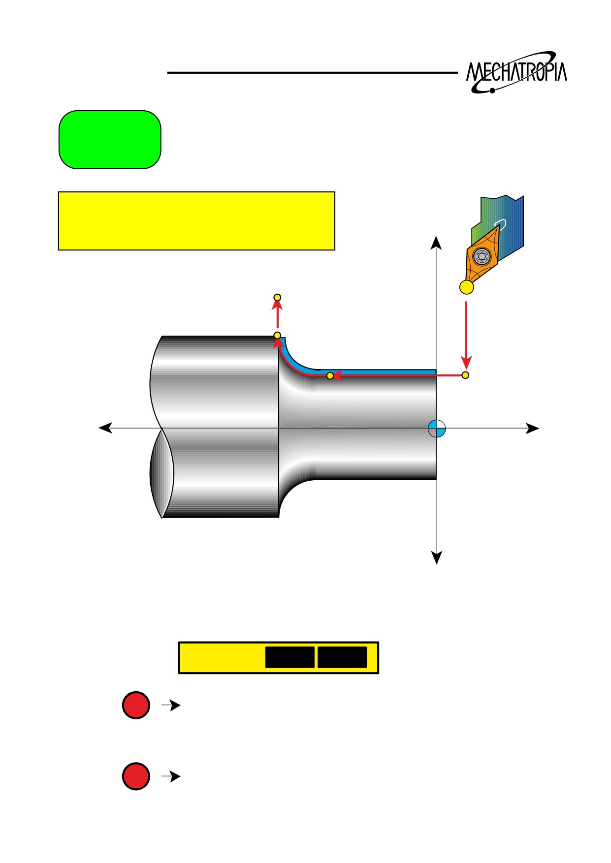
G70
FINISHING CYCLE
G70 P Q
:
+X
N70
N55
N60
N60
-Z
+Z
-X
N..
N50 G70
P55
Q70
P
N55 G0 G42 X..
N60 G1 Z-..
N65 G2 X.. Z.. R..
Q
N70 G1 G40 X..
N..
31
TRAINING
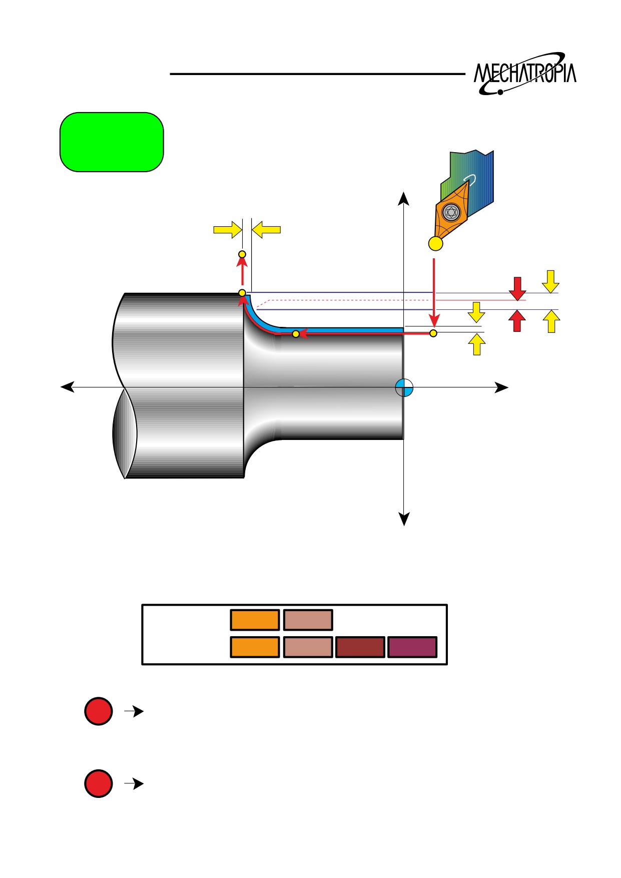
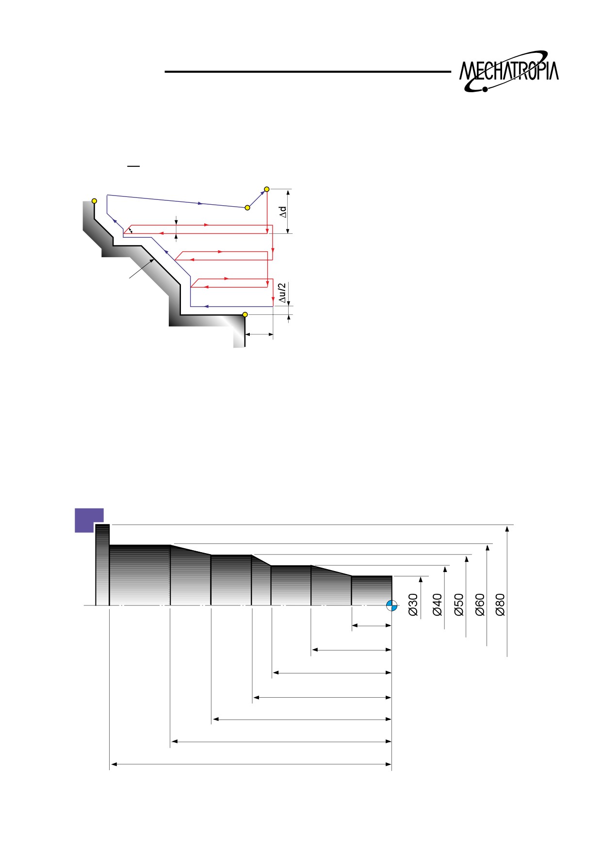
G71
+X
W+
N75
N60
R U
U+
N70
N65
-Z
+Z
-X
N..
N50 G71
U..
R..
N55 G71
P60
Q75
U+..
W+..
P
N60 G0 G42 X..
N65 G1 Z-..
N70 G2 X.. Z-.. R..
Q
N75 G1 G40 X..
N..
32
TRAINING
G71(STOCK REMOVAL IN TURNING)
G71 U( ¡ d) R(e) :
G71 P Q U( ¡ u) W( ¡ w) F :
P : Start sequence no.
C
B
Q : Final sequence no.
(R)
A
(R)
U( ¡ d) : Cut volume of one time(Designate
(F)
e
45°
(F)
the radius.
R(e) : Escape volume(Always 45) escape
Program command
U( ¡ u) : Finishing tolerance in X axis
W( ¡ w) : Finishing tolerance in Z axis
(F) : Cutting feed
(R) : Rapid traverse
A`
F(f) : Cutting feedrate
Δw
Example of program
20
40
60
70
90
110
140
33
TRAINING
(G70, G71)
N10 G50 S1500 T0101 :
G96 S180 M03 :
G00 X85.0 Z5.0 M08 :
Z0 :
G01 X-1.6 F0.25 :
G00 X83.0 Z2.0 :
G71 U3.0 R1.0 :
G71 P20 Q30 U0.5 W0.1 F0.27 :
N20 G42 G00 X30.0 :
G71 CYCLE CUTTING FEED
G01 Z-20.0 F0.17 :
G70 CYCLE CUTTING FEED
X40.0 Z-40.0 :
Z-60.0 :
X50.0 Z-70.0 :
Z-90.0 :
X60.0 Z-110.0 :
Z-140.0 :
X80.0 :
N30 G40 :
G70 P20 Q30 : (When using the same bite)
G00 X200.0 Z200.0 T0100 :
M30 :
¡¯ When finishing, if a different bite is used
G00 X200.0 Z200.0 T0100 :
M01 :
N40 G50 S2000 T0303 :
G96 S200 M03 :
G00 X83.0 Z2.0 M08 :
G70 P20 Q30 :
G00 X200.0 Z200.0 T0300 :
M30 :
34
TRAINING
Examples of program
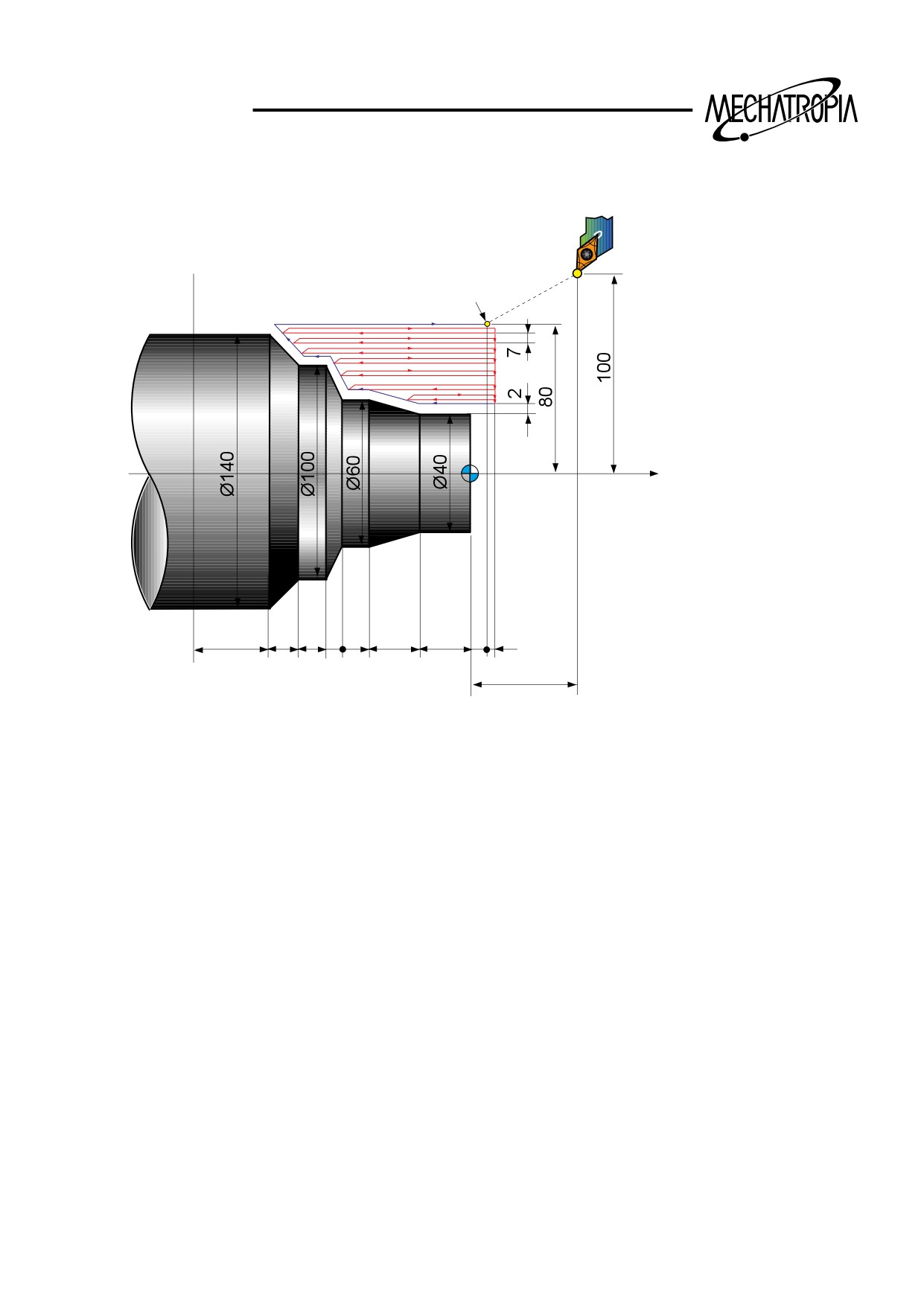
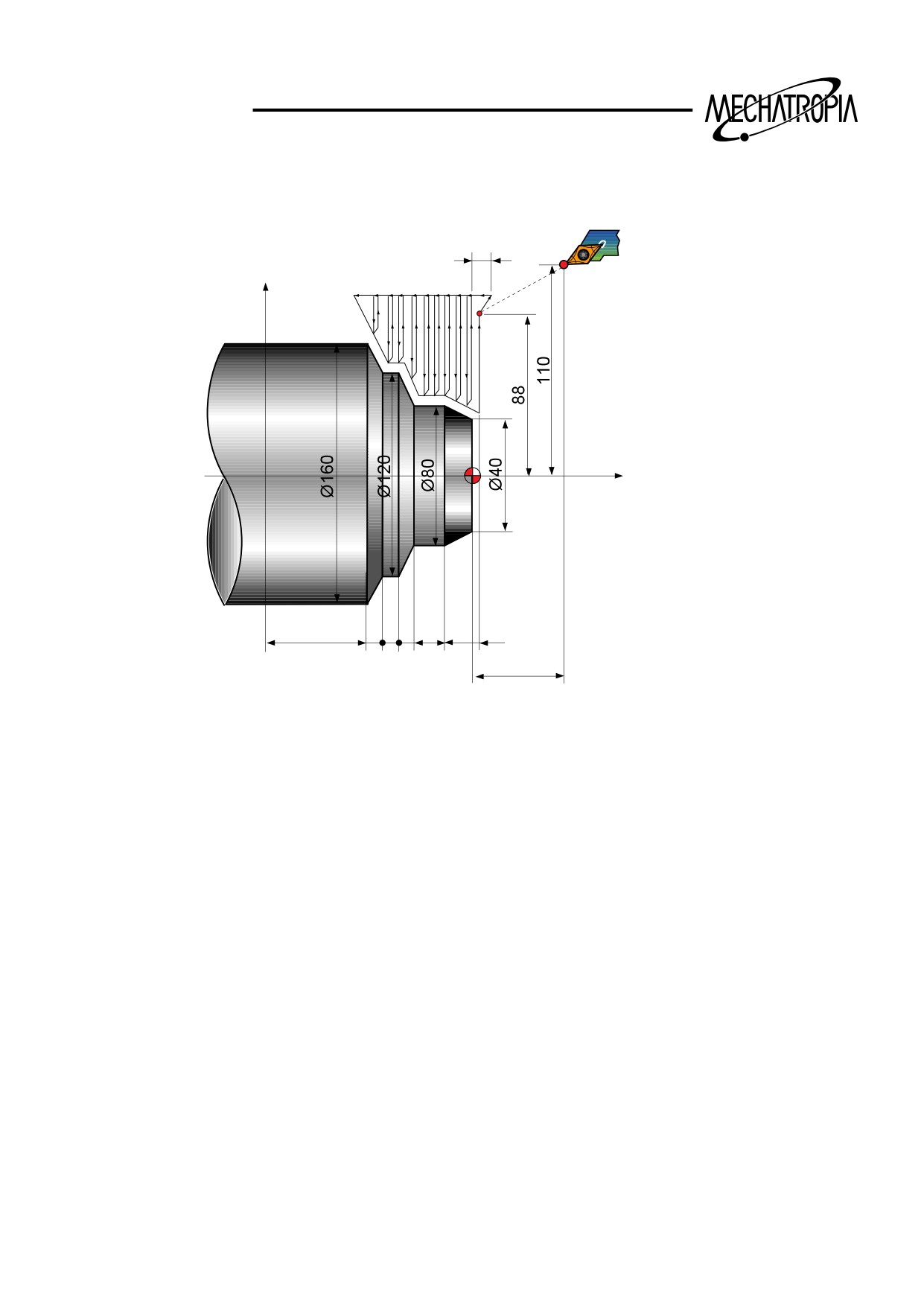
Stock Removal in Turning(G71) (Type I)
X
Start point
End point
Z
40
20
2010
20
30
30
10
2
100
(Diameter designation, metric input)
N010 G00 X200.0 Z100.0 :
N011 G00 X160.0 Z10.0 :
N012 G71 U7.0 R1.0 :
N013 G71 P014 Q021 U4.0 W2.0 F0.3 S550 :
N014 G00 G42 X40.0 S700 :
N015 G01 W-40.0 F0.15 :
N016
X60.0 W-30.0 :
N017
W-20.0 :
N018
X100.0 W-10.0 :
N019
W-20.0 :
N020
X140.0 W-20.0 :
N021
G40 U2.0 :
N022 G70 P014 Q021 :
N023 G00 X200.0 Z100.0 :
M30 :
35
TRAINING
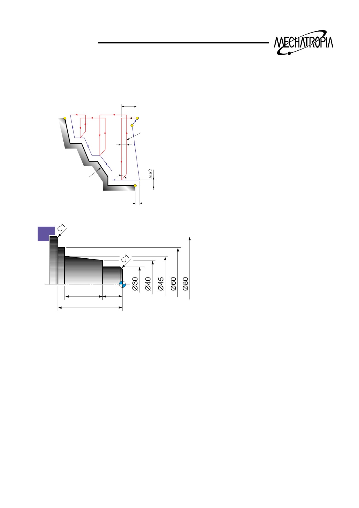
G72(STOCK REMOVAL IN FACING)
G72 W( ¡ d) R(e) :
G72 P_ Q_ U( ¡ u) W( ¡ w) F :
Δd
U( ¡ d) : Cut volume of one time
A`
R(e) : Escape volume
C
A
P : Start sequence No.
Tool path
(F)
Q : Final sequence No.
e
(R)
(R)
U( ¡ u) : Finishing in clearance X axis(Diameter
command)
45°
(F)
W( ¡ w) : Finishing in clearance Z axis
Program command
B
F(f) : Cutting feedrate
Δw
Example of program
X40.0 Z-15.0 :
X30.0 :
Z-1.0 :
X26.0 Z1.0 :
N14 G40 :
30
15
G70 P12 Q14 :
50
G00 X200.0 Z200.0 T0100 :
M30 :
N10 G50 S2000 T0100 :
G96 S180 M03 :
¡¯(When finishing with a different tool)
G00 X200.0 Z200.0 T0100 :
G00 X85.0 Z5.0 T0101 :
Z0 :
M01 :
G01 X-1.6 F0.2 :
N16 G50 S2500 T0300 :
G00 X85.0 Z1.0 :
G96 S200 M03 :
G72 W2.0 R1.0 :
G00 X85.0 Z5.0 T0303 :
G72 P12 Q14 U0.5 W0.2 F0.25 :
G70 P12 Q14 :
N12 G00 G41 Z-51.0 :
G00 X200.0 Z200.0 T0300 :
G01 X80.0 F0.2 :
M30 :
X78.0 W1.0 :
X60.0 :
Z-45.0 :
36
TRAINING
Examples of program
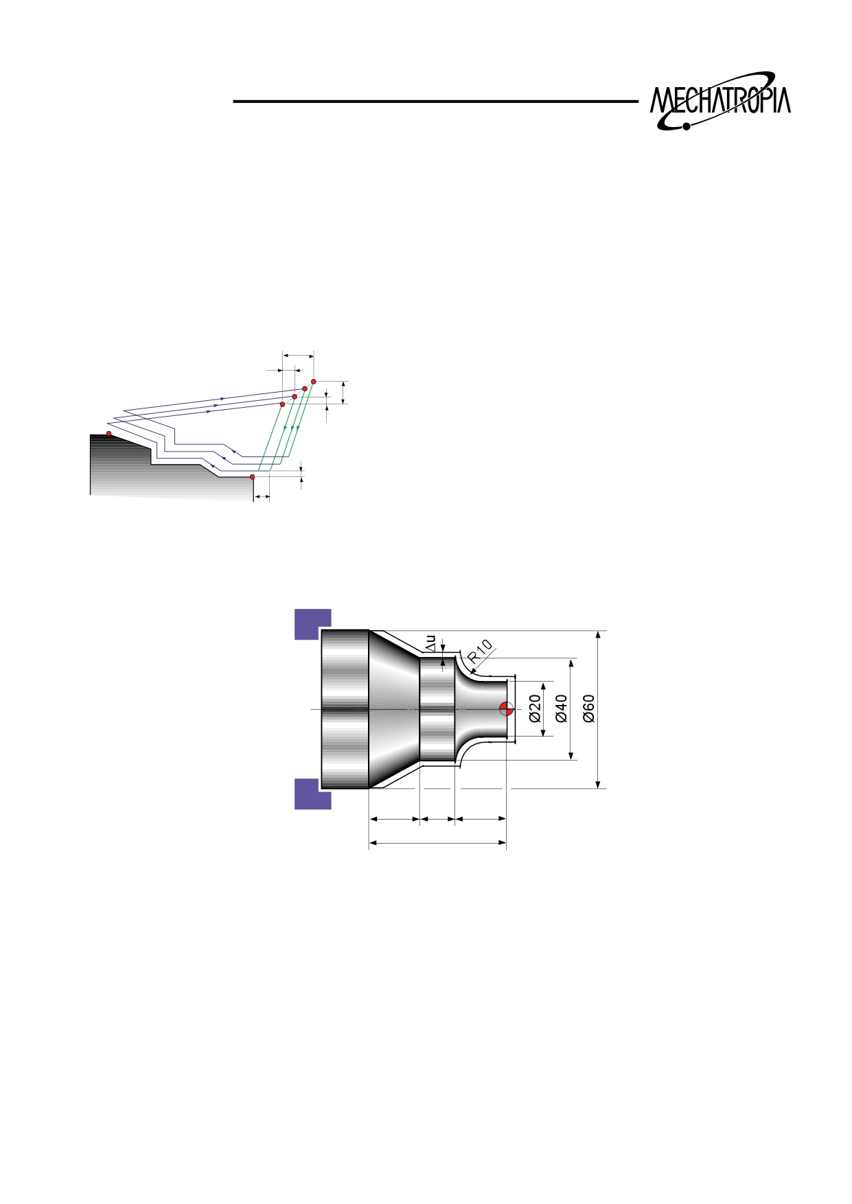
Stock Removal in Pacing(G72)
7
X
Start point
Z
60
101010
20
20
2
60
(Diameter designation, metric input)
N010 G00 X220.0 Z60.0 :
N011 G00 X176.0 Z2.0 :
N012 G72 W7.0 R1.0 :
N013 G72 P014 Q021 U4.0 W2.0 F0.3 S550 :
N014 G00 G41 Z-70.0 S700 :
N015 X160.0 :
N016 G01 X120.0 Z-60.0 F0.15 :
N017
W10.0 :
N018
X80.0 W10.0 :
N019
W20.0 :
N020
X36.0 W22.0 :
N021
G40 :
N022 G70 P014 Q021 :
N023 G00 X220.0 Z60.0 :
N024 M30 :
37
TRAINING
G73(PATTEN REPEATING)
G73 U( ¡ i) R(d) W( ¡ k) :
G73 P Q U( ¡ u) W( ¡ w) F :
U( ¡ i) : Excape distance and direction in X axis
(Designated the radius)
W( ¡ k) : Escape distance and direction in Z axis
Δk+Δw
Δw
D
R(d) : Repeating time
C
Δi+Δu/2
(It is conneeted with the cut volume of each time)
A
Δu/2
(R)
B
P : Start sequence No.
Q : Final sequence No.
Δu/2
A`
Δw
U( ¡ u) : Finishing in clearance X axis(Radius des-
ignated)
W( ¡ w) : Finishing in clearance Z axis
F(f) : Cutting feedrate
Example of program
20
10
20
50
N10 G50 S2000 T0300 :
N12 G00 G42 X20.0 Z2.0 :
G96 S200 M03 :
G01 Z-10.0 F0.15 :
G00 X35.0 Z5.0 T0303 :
G02 X40.0 Z-20.0 R10.0 :
Z0 :
G01 Z-30.0 :
G01 X-1.6 F0.2 :
X60.0 Z-50.0 :
G00 X70.0 Z10.0 :
N16 G40 U1.0 :
G73 U3.0 W2.0 R2 :
G70 P12 Q16 :
G73 P12 Q16 U0.5 W0.1 F0.25 :
G00 X200.0 Z200.0 T0300 :
M30 :
38
TRAINING
Examples of program
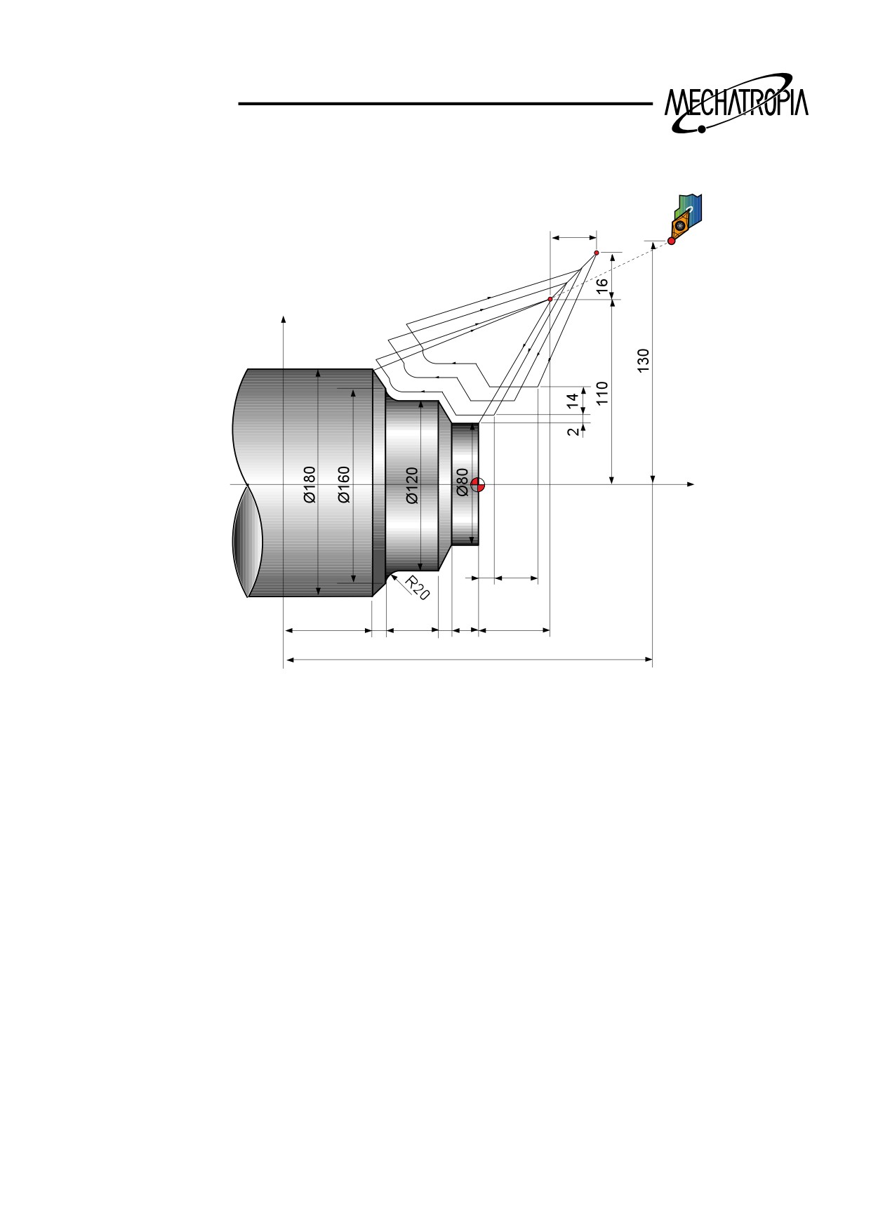
Pattern Repeating(G73)
16
Start point
X
Z
2
14
60
10
40
10
20
40
220
(Diameter designation, metric input)
N010 G00 X260.0 Z80.0 :
N011 G00 X220.0 Z40.0 :
N012 G73 U14.0 W14.0 R3 :
N013 G73 P014 Q020 U4.0 W2.0 F0.3 S0180 :
N014 G00 G42 X80.0 Z2.0 :
N015 G01 W-20.0 F0.15 S0600 :
N016 X120.0 W-10.0 :
N017 W-20.0 S0400 :
N018 G02 X160.0 W-20.0 R20.0 :
N019 G01 X180.0 W-10.0 S0280 :
N020 G40 :
N021 G70 P014 Q020 :
N022 G00 X260.0 Z80.0 :
N023 M30 :
39
TRAINING
G74
+X
-Z
+Z
Q
-Z
-X
N40
G74
R..
N50
G74
Z-..
Q..
F..
40
TRAINING
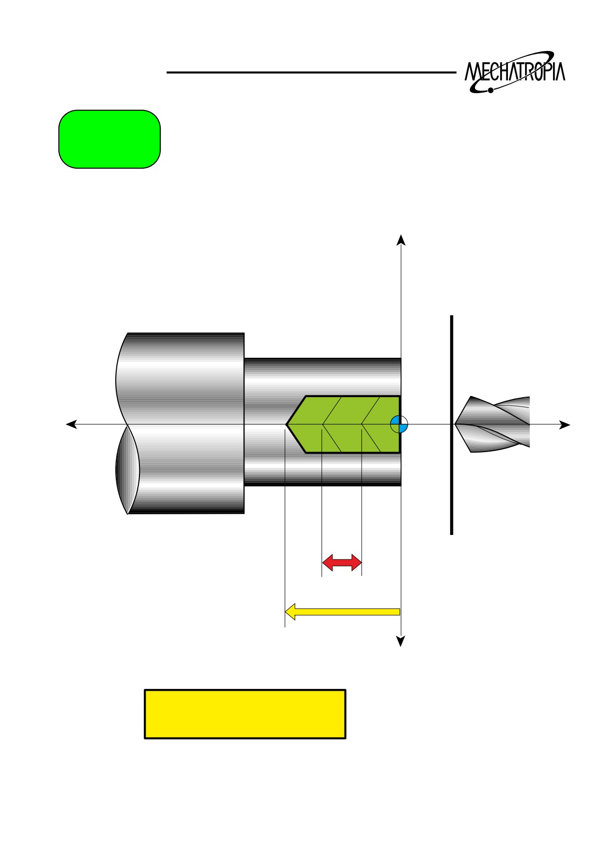
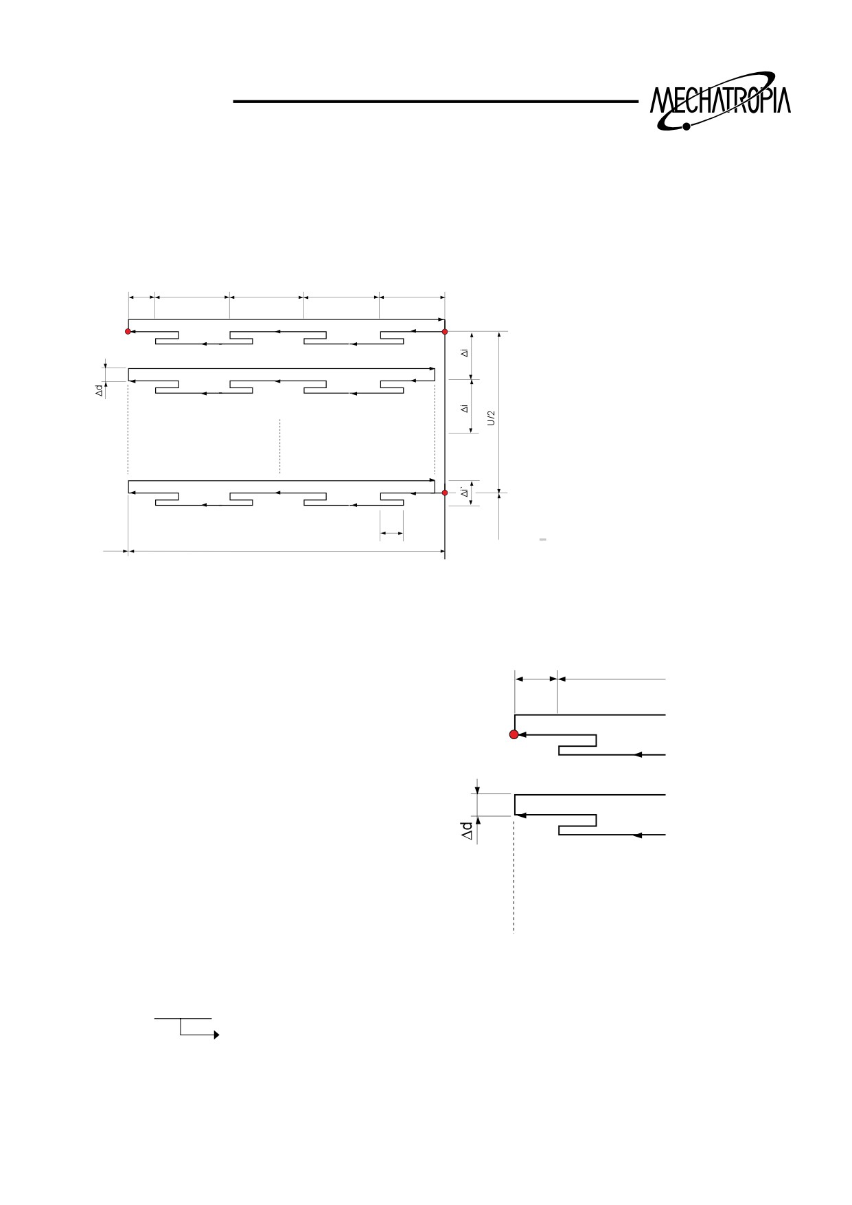
G74(Peck drilling in Z axis divection)
1) Drill cutting cycle
G74 R(e) :
G74 Z(w) Q( ¡ k) F :
Δk`
Δk
Δk
Δk
Δk
R(e) : Retreat volume
C
A
Z(w) : Final cutting depth
Q( ¡ k) : One time cutting depth
(R)
(R)
(R)
(R)
(F)
(1000=1mm)
(F)
(F)
(F)
(F)
F : Cutting feedrate
B
X
e
[0 < Δi` < Δi ]
W
Z
(R) : Radius traverse
(F) : Cutting feed
Examples of program
Δk`
Δk
C
(R)
(F)
(F)
N10 G50 S500 T0200 :
G74 R1.0 :
G97 S280 M03 :
G74 Z-90.0 Q5000 F0.23 :
G00 X0 Z5.0 T0202 M08 :
G00 X200.0 Z150.0 T0200 :
Start point of drilling
M01 :
41
TRAINING
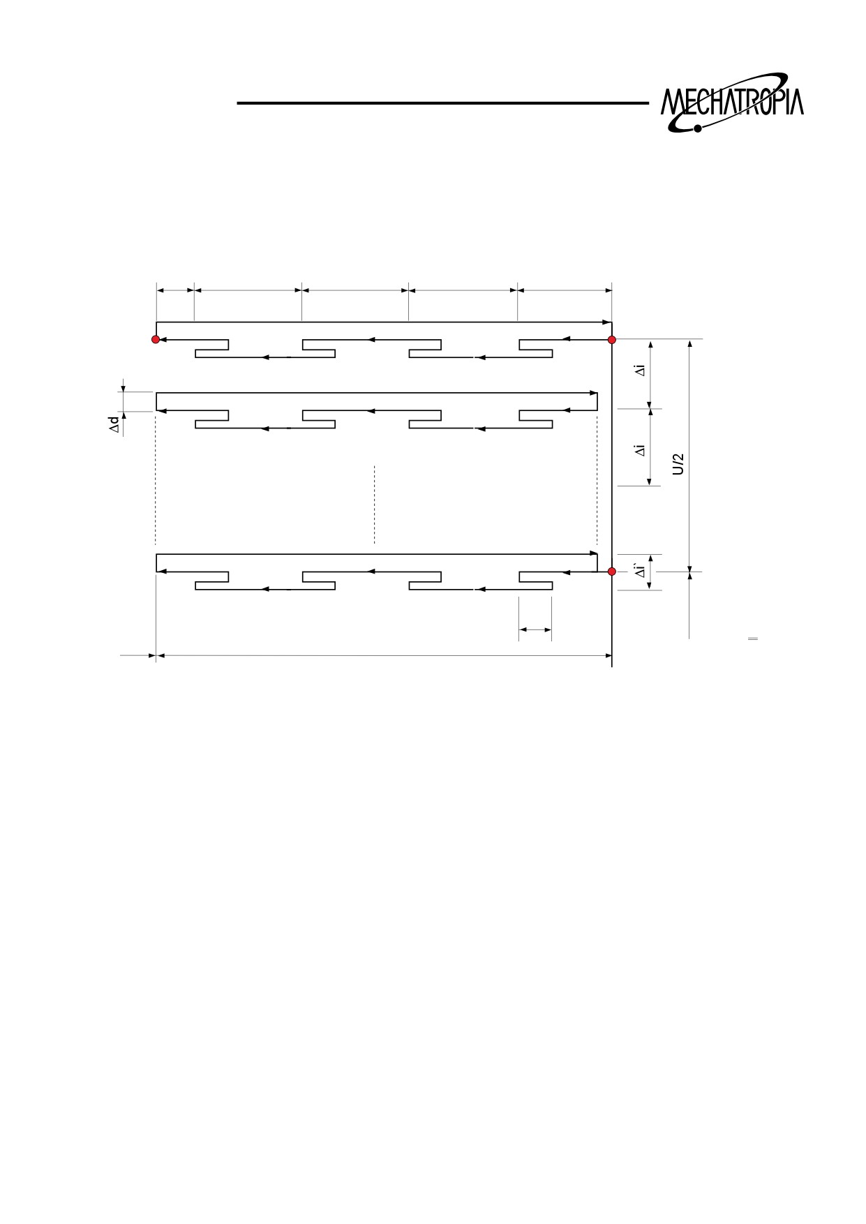
2) Stock removal cycle in side
G74 R(e) :
G74 X(u) Z(w) P( ¡ i) Q( ¡ k) R( ¡ d) F :
Δk`
Δk
Δk
Δk
Δk
C
A
(R)
(R)
(R)
(R)
(F)
(F)
(F)
(F)
(F)
B
X
e
[0 < Δi` < Δi ]
W
(R) : Radius traverse
Z
(F) : Cutting feed
R(e) : Retreat volume(Modal command)
P( ¡ i) : Moving volume of X axis
Q( ¡ k) : Cut volume in Z axis(Q5000=5mm)
X(u) : Composition of X axis
Z(w) : Final cutting depth
R( ¡ d) : Escape wlume at the end point of Z axis proess(Designate the symbol and
radius according to the direction of escape)
F : Cutting feedrate
42
TRAINING
10
10
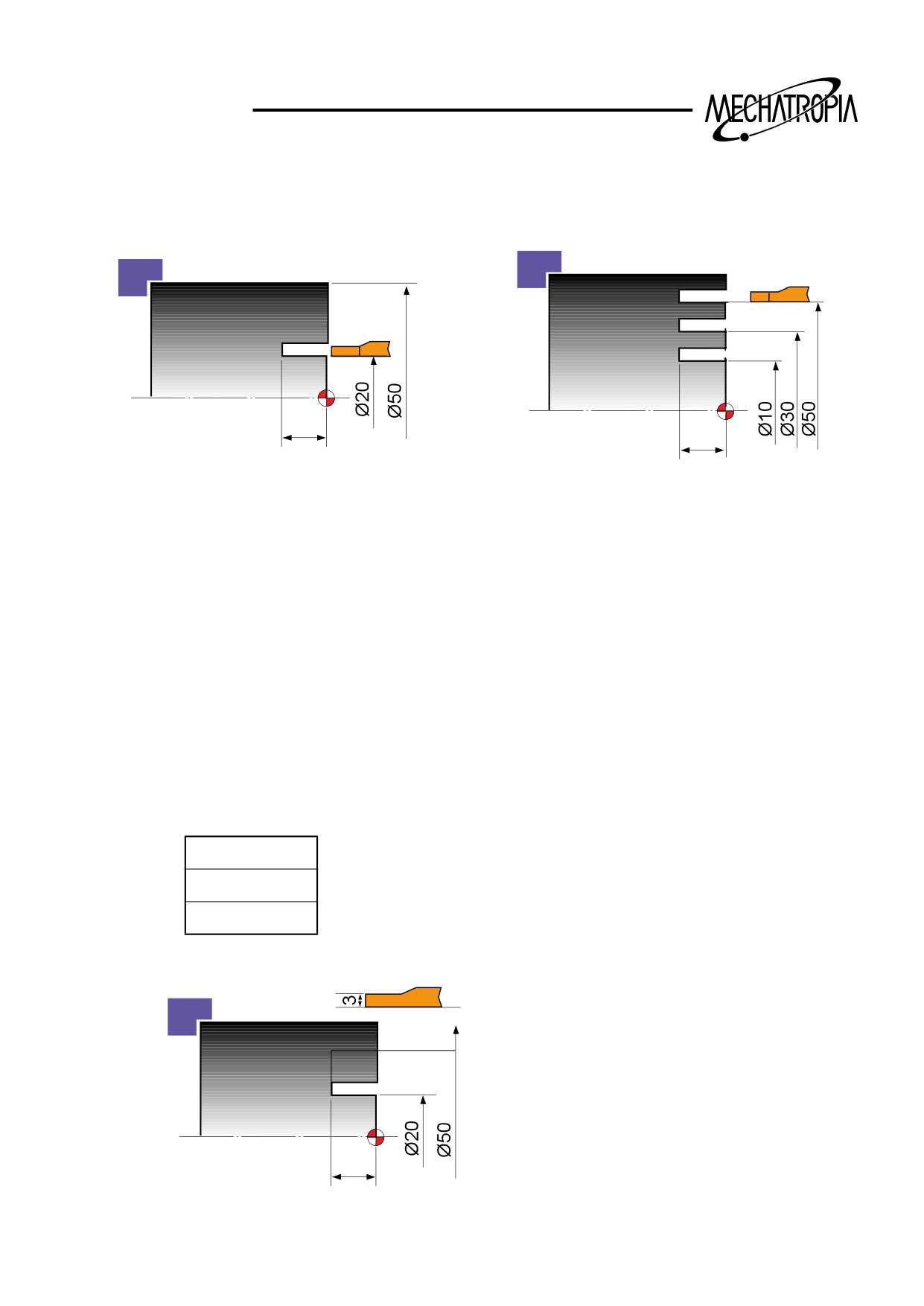
¡¯ If there is one groove, X(u), P( ¡ i) can be omitted.
(In case of omitting, it shall be done at the same time)
N10
N10 G50 S2000 T0100 :
G00 X20.0 Z1.0 :
G96 S80 M03 :
G74 R1.0 :
G00 X50.0 Z1.0 T0101 :
G74 R1.0 :
G74 Z-10.0 Q3000 F0.1 :
G74 X10.0 Z-10.0 P10000 Q3000 F0.1 :
G00 X200.0 Z200.0 :
G00 X200.0 Z200.0 T0100 :
M30 :
M30 :
Attention
FANUC 0TC
N1 G50 S2000 T0100 :
Q3000=3mm
G96 S80 M3 :
P10000=10MM
G0 X47.0 Z1.0 T0101M8 :
G74 R1.0 :
G74 Z-10.0 Q3000 F0.1 :
G0 U-5.0 :
Ø50
G74 X20.0 Z-10.0 P2500 Q3000 F0.1 :
G0 X200.0 Z200.0 T0100 :
M30 :
10
43
TRAINING
G75
Q<T!
Z = I - T!
+X
t
P
R
-Z
Q
+Z
X
Z
I
P... ( ¥ M )
-X
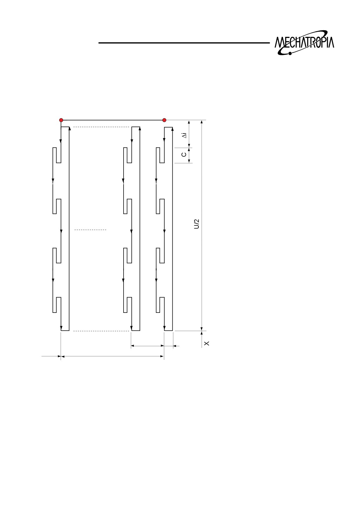
N50 G75 R
N55 G75 X... Z-... P... Q...
44
TRAINING
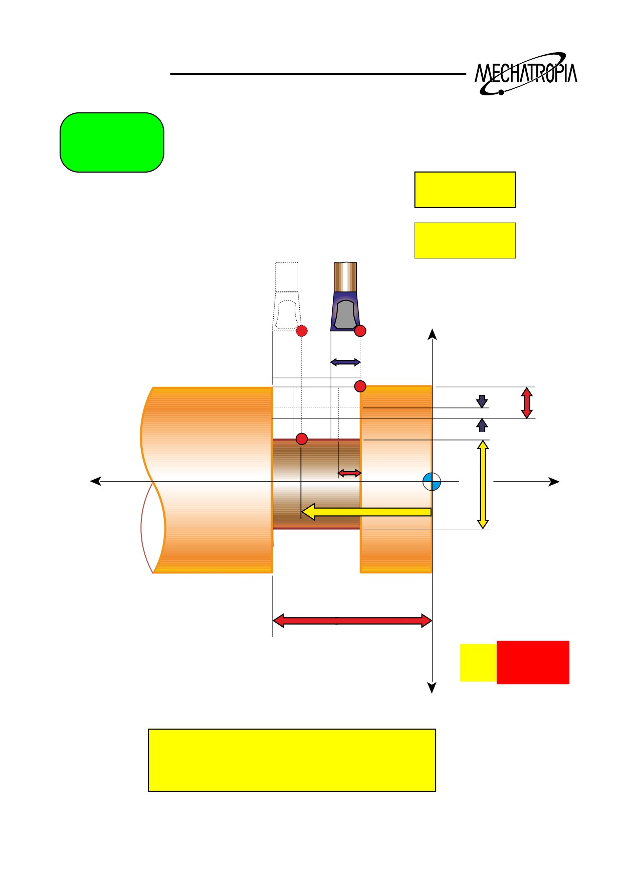
G75(X directiion grooving : Peck drill cycle in turining)
G75 R(e) :
G75 X(u) Z(w) P( ¡ i) Q( ¡ k) R( ¡ d) F :
(R)
A
(F)
(R)
(F)
(R)
(F)
(R)
(F)
(R)
(F)
ΔΚ
Δd
W
Z
(R) : Radius traverse
(F) : Cutting feed
R(e) : Retreat volume(Modal command)
X(u) : Compostion of X axis
Z(w) : Composition of Z axis
Q(k) : Moving volume in Z axis(Designate with out symblo)
P(i) : Cut volume or X axis(Designate the radius)
R(d) : Escape volume at the end point of X axis process
(Designate the symble according to escape dinetion)
F : Cutting feedrate
45
TRAINING
10
60
40
20
10
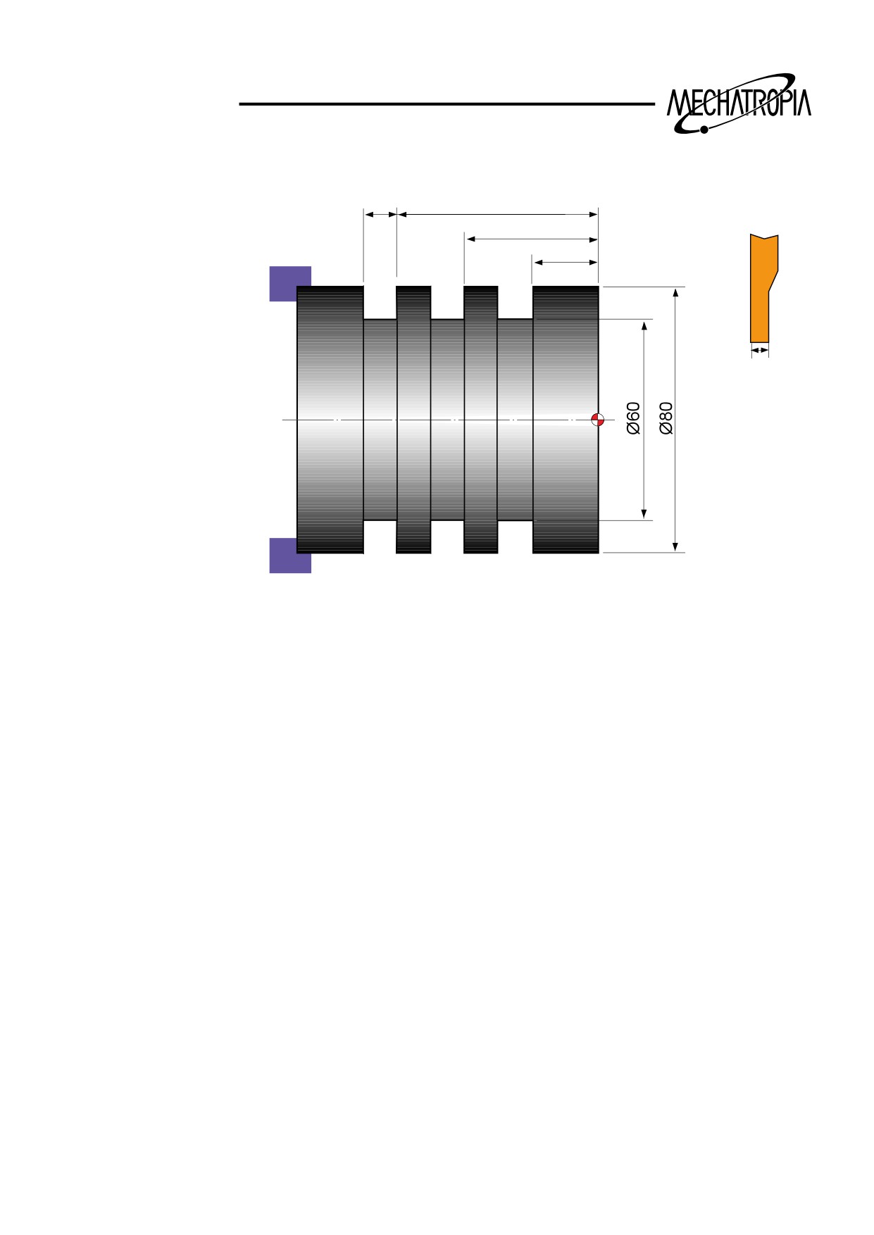
N10 G50 S500 T0100 :
G97 S_ M03 :
G00 X90.0 Z1.0 T0101 :
X82.0 Z-60.0 :
G75 R1.0 :
G75 X60.0 Z-20.0 P3000 Q20000 F0.1 : ¡¸¡£
G00 X90.0
X200.0 Z200.0 T0100 :
M30 :
¡¯While it has the same function with G74, X and Z are exchanged.
If there is one groove, volues of Z and P can be omitted at the same time.
46
TRAINING
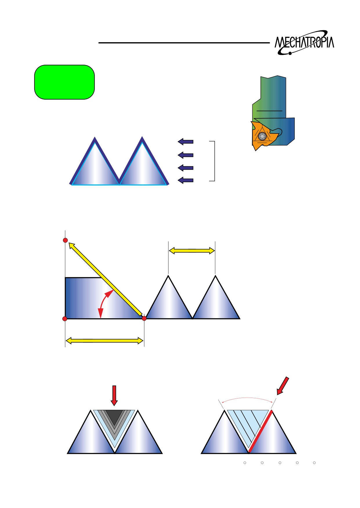
G76
N50
G76
Pxx xx xx
Q...
R...
N55
G76
X...
Z... R0
P...
Q...
F...
1
1
Pxx
(0 - 99)
n
N50
G76
Pxx xx xx
Q...
R...
N55
G76
X...
Z... R0
P...
Q...
F...
F
Pxx
a = F*(
)
10
45Ο
Pxx
(0 - 99)
a
N50
G76
Pxx xx xx
Q...
R...
N55
G76
X...
Z... R0
P...
Q...
F...
α
Pxx = 0
Pxx = α ( 80 , 60 , 55 , 30 , 29 )
47
TRAINING
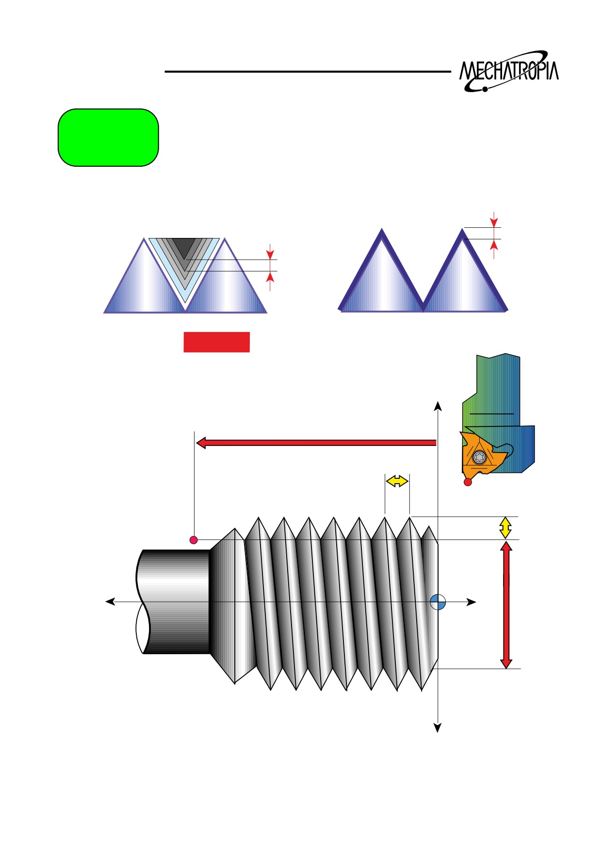
G76
N50
G76
Pxx xx xx
Q...
R...
N55
G76
X...
Z... R0
P...
Q...
F...
R
Q(Xmin)
Q ..
( µm )
+X
Z
F
P
-Z
+Z
X
N50
G76
Pxx xx xx
Q...
R...
N55
G76
X...
Z... R0
P...
Q-X.
F...
48
TRAINING
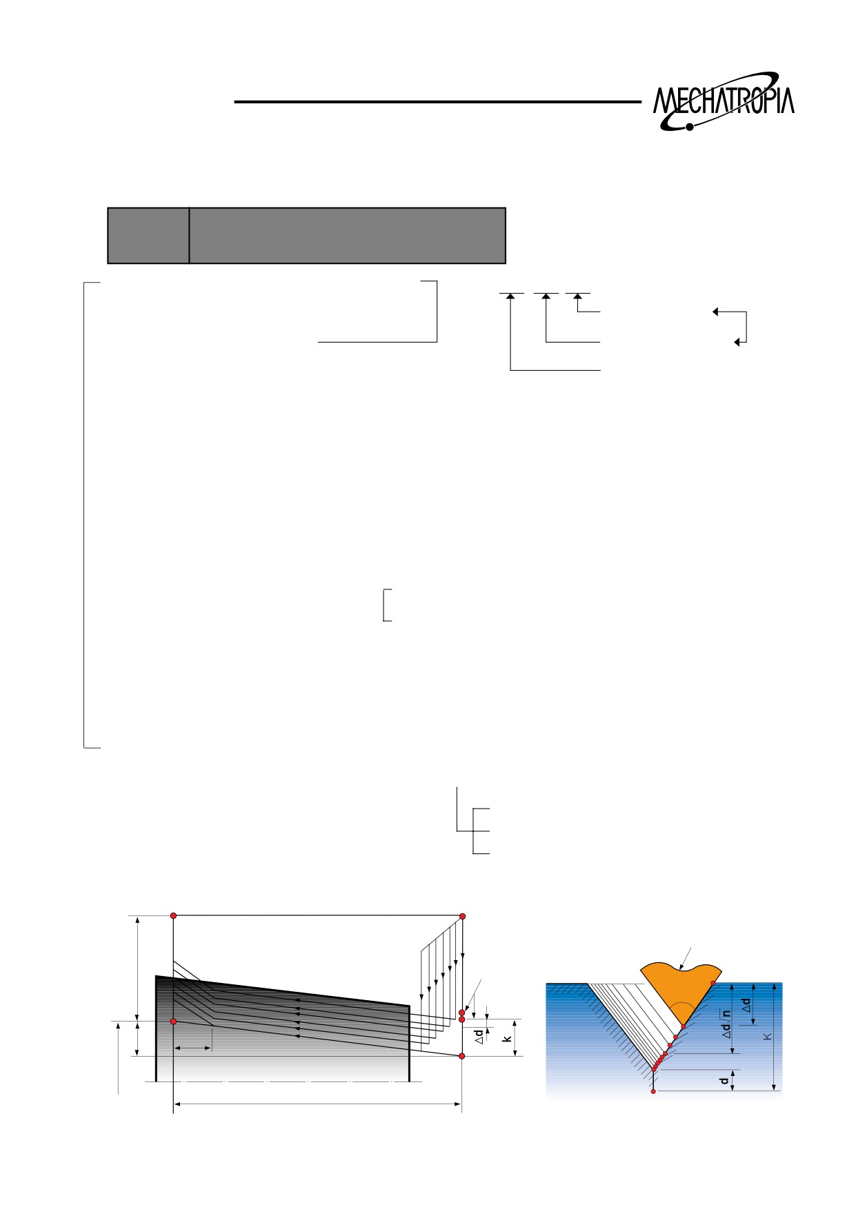
G73(Compound type thread cutting cycle)
By G76 command, thread cutting cycle is possible.
FORMAT
G76 P(m) (r) (a) Q(Δdmin) R(d)
G76 X(u) Z(w) R(i) P(k) Q(Δd) F(f)
P(m) : Repeating time before the final thread
ex) P 0 2 1 0 6 0
(r)
: Chamfering at the end part of thread
Angle of thread face
(a)
: Angle between threads
Chanfering volume 1.0 lead
omissible
Repeating time
Q( §Edmin) : Min. cut volume(Example : Calculate as Q100=NC and process at least more
than 0.1 for processing of one time)-0.1(Decimal point is vot allowed)
R( §Ed) : Finishing clearance(Final finishing clearance)
X(u)
: Core diameter of thread
(Command the value of Outer diameter of thread-<height of threadx2>)
Z(w)
: Z spindle coordinate at the end point of thread process
R(i)
: For omitting, straight thread and R- : X+ and Taper thread
R+ : X- and Taper thread
P(k) : Height of thread(Omit the decimal point <Example>P900=0.9mm)
Q(d) : Initial cut volume (Omit the decimal point <Example>Q500=Designate) the radius
value
F(f)
: Cutting feedrate(Lead)
*P(k) : 0.6 x Pitch = Core diameter of thread
Hikgh value
Midium value = 0.6
Low value
(Exampal1) G76 Compound type thread cycle
E
(R)
A
Tool tip
U/2
B
B
(F)
(R)
a
1st
D
i
r
2nd
3rd
nth
C
Z
w
X
49
TRAINING
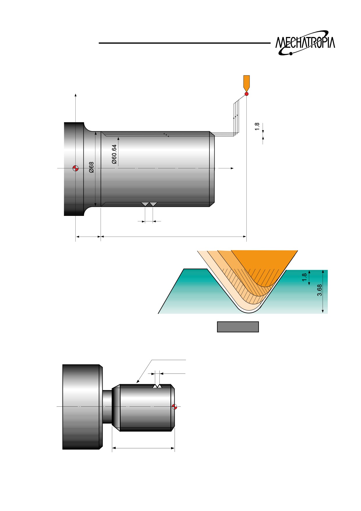
(Exampal1) G76 Compound type thread cycle
X
Z
6
25
105
G00 X80.0 Z130.0 :
G76 P011060 Q100 R200 :
G76 X60.64 Z25.0 P3680 Q1800 F6.0 ;
PROGRAM
N10 G97 S1000 M03
M30x2.0
T0100
G00 X50.0 Z5.0 T0101
P=1.5
G76 P021060 Q100 R100
G76 X28.2 Z-32.0 P900 Q500 F1.5
G00 X200.0 Z200.0 T0100
M30
*
30
50
TRAINING
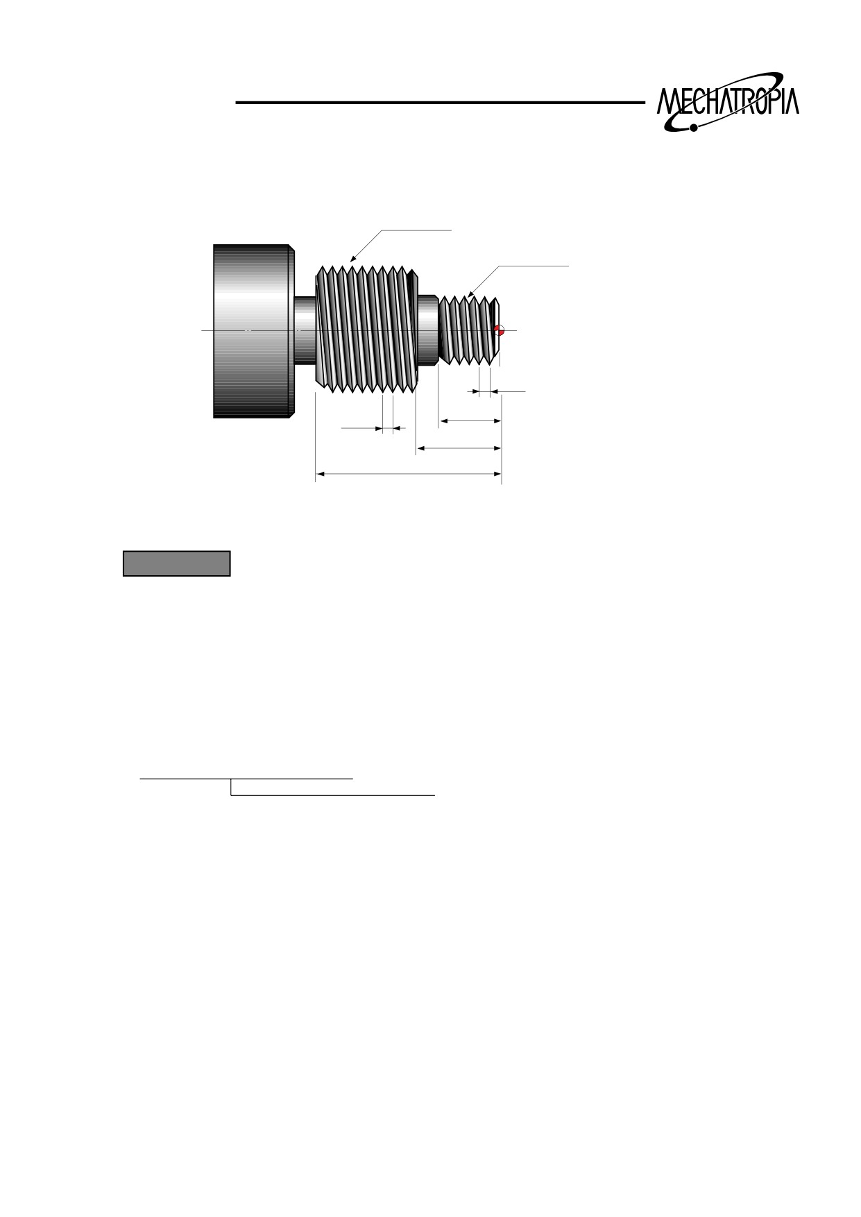
(Exampal1) G76 Compound type thread cycle
M40x1.5
M20x1.5
P=1.5
20
P=1.5
25
50
PROGRAM
N10 G97 S800 M03
T0300
G00 X30.0 Z5.0 T0303
G76 P021060 Q100 R100
G76 X18.2 Z-20.0 P900 Q500 F1.5
G00 X50.0 Z-20.0
G76 P021060 Q100 R100
Omissible
G76 X38.2 Z-52.0 P900 Q500 F1.5
G00 X200.0 Z200.0 T0300
M30
*
51
TRAINING
G90
G00
G01
+X
-Z
+Z
50
-X
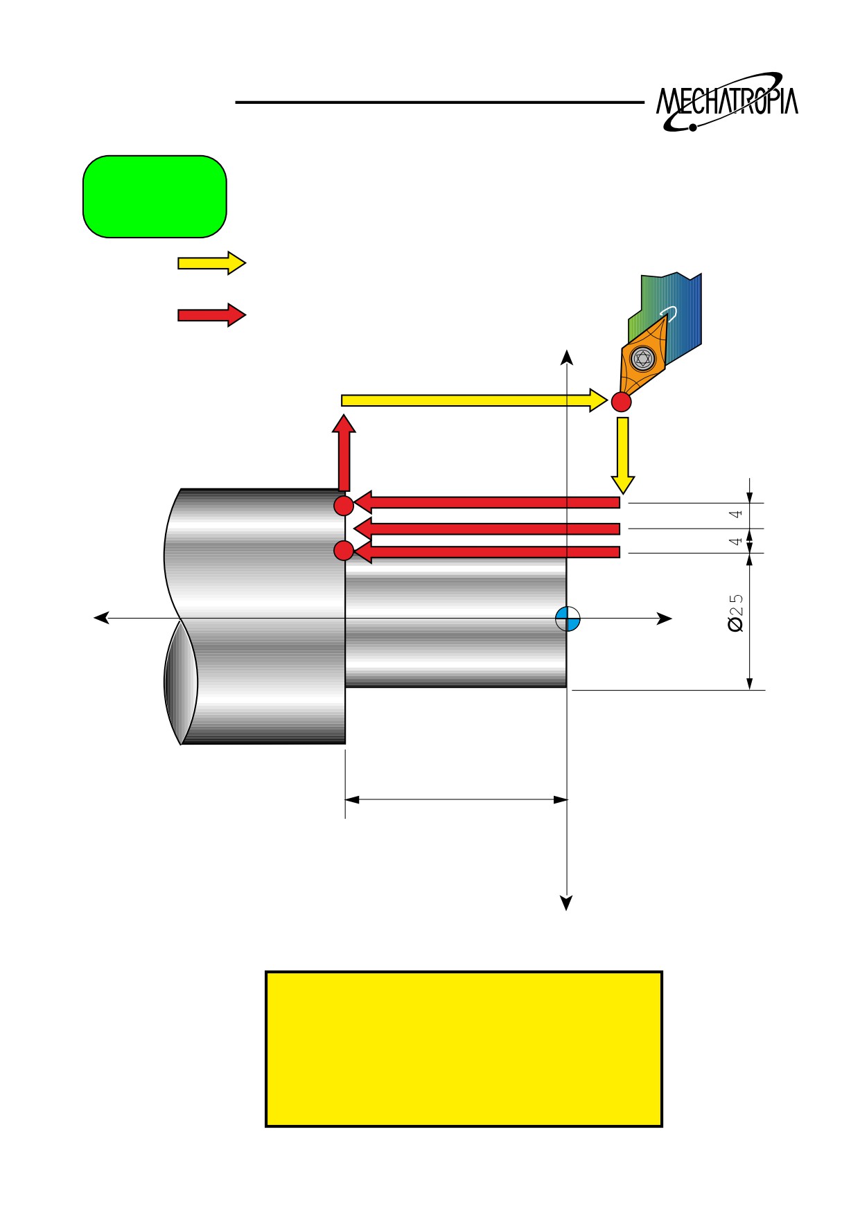
N1234 G90
N1235 G90 X41 Z-50
N1236 U-8
N1237 U-8
52
TRAINING
G90 Fixed cycle
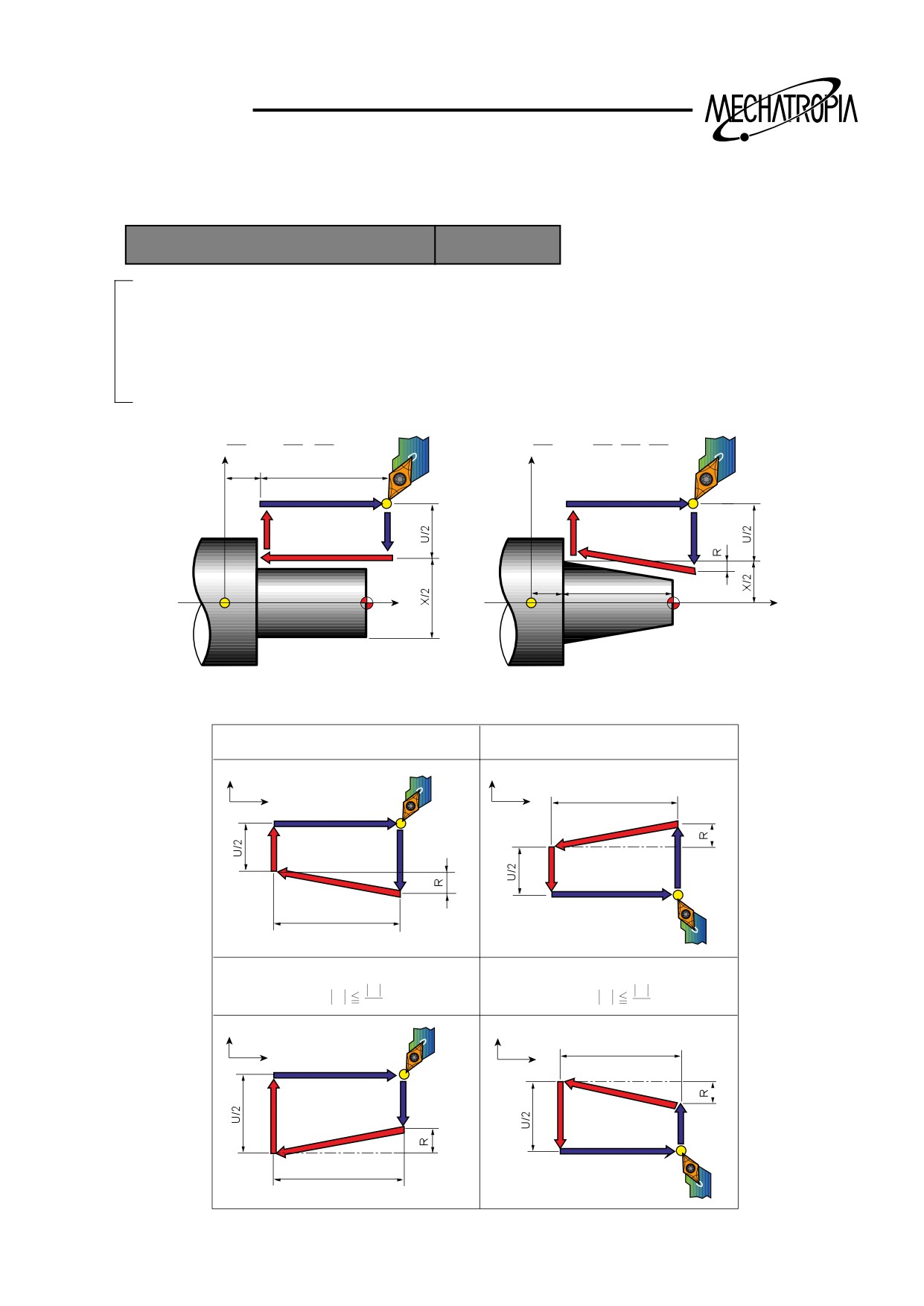
1) Single fixed cycle for cutting
FORMAT G90 X(U) Z(W) _R _F_
Taper cutting
X(U)
: X coordinate at the tnd point of Z
Z(W)
: End point
R-
: When cutting from the start point to X+ direction
R+
: When cutting from the start point to X- direction
I/R
: Inclination(Designate the radius value)
G90X(U)
Z(W)
F
;
G90X(U)
Z(W)
R
F
;
X
X
Z
W
4(R)
3(F)
1(R)
2(F)
Z
Z
W
Z
R... Rapid traverse
F... Cutting traverse specified by F code
1. U<0, W<0, R<0
2. U>0, W<0, R>0
X
X
W
Z
Z
2(F)
4(R)
3(F)
1(R)
3(F)
1(R)
4(R)
2(F)
W
3. U<0, W<0, R>0
4. U>0, W<0, R<0
U
U
at
R
at
R
2
2
X
X
W
Z
Z
4(R)
1(R)
2(F)
3(F)
3(F)
2(F)
1(R)
4(R)
W
53
TRAINING
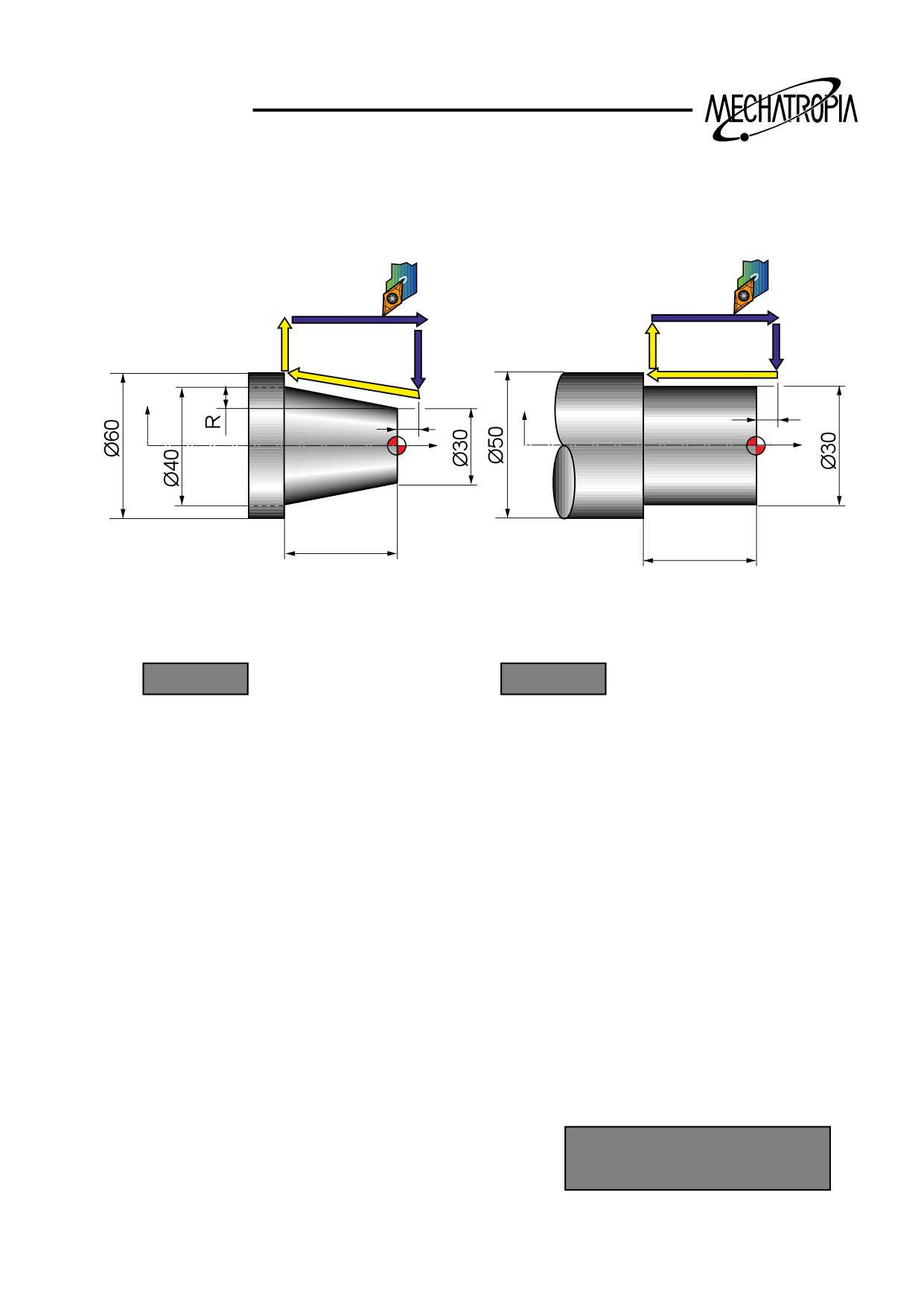
Exampal1) When the taper is R
Example)
X
X
2
2
Z
Z
40
30
PROGRAM
PROGRAM
G30 U0 W0 :
G30 U0 W0 :
G50 S2000 T0100 :
G50 S2000 T0100 :
G96 S200 M03 :
G96 S200 M03 :
G00 X61.0 Z2.0 T0101 M8 :
G00 X56.0 Z2.0 T0101 M08 :
G90 X55.0 W-42.0 F0.25 :
X50.0 :
G90 X51.0 W-32.0 F0.25 :
X45.0 :
X46.0 :
X40.0 :
X41.0 :
Z-12.0 R-1.75 :
X36.0 :
Z-26.0 R-3.5 :
X31.0 :
Z-40 R-5.25 :
X30.0 :
G30 U0 W0 :
G30 U0 W0 :
M30 :
M30 :
ƒT
When cutting of inside diame-
ter,above format can be used.
54
TRAINING
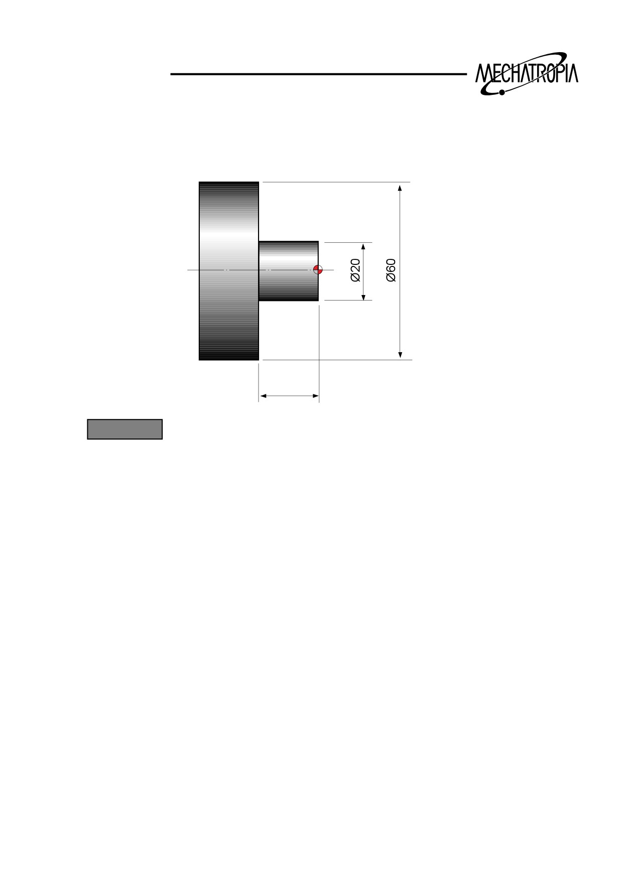
(Exampal1) G90 Fixed cycle
20
PROGRAM
N10 G50 S2000
G96 S180 M03
T0100
G00 X65.0 Z3.0 T0101
G90 X55.0 Z-20.0 F0.25
X50.0
X45.0
X40.0
X35.0
X30.0
X25.0
X20.5
X20.0
G00 X200.0 Z200.0 T0100
M30
ƒT
55
TRAINING
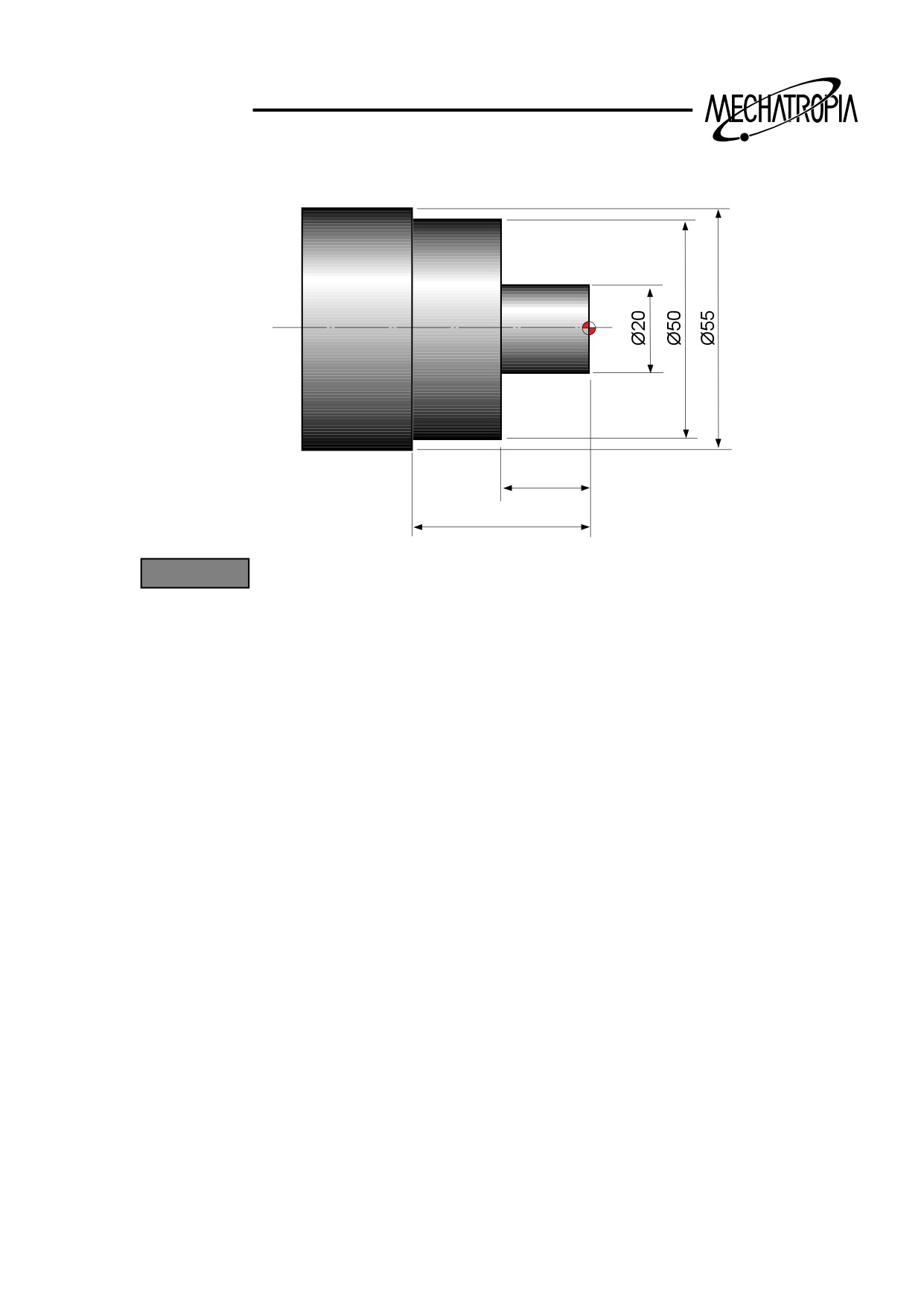
(Exampal2) G90 Fixed cycle
20
40
PROGRAM
ex1)
ex2)
N10 G50 S2000
N10 G50 S2000
G96 S180 M3
G96 S180 M03
T0100
T0100
G0 X60.0 Z5.0 T0101 M8
G00 X60.0 Z0 T0101
G90 X50.0 Z-40.0 F0.25
G01 X-1.6 F0.2
X45.0 Z-20.0
G00 X50.0 Z1.0
X40.0
G01 Z-40.0 F0.25
X35.0
G00 U1.0 Z1.0
X30.0
G90 X45.0 Z-20.0 F0.25
X25.0
X40.0
X20.0
X35.0
G00 X200.0 Z200.0 T0100
X30.0
M30
X25.0
X20.5
X20.0
G00 X200.0 Z200.0 T0100
M30
ƒT
56
TRAINING
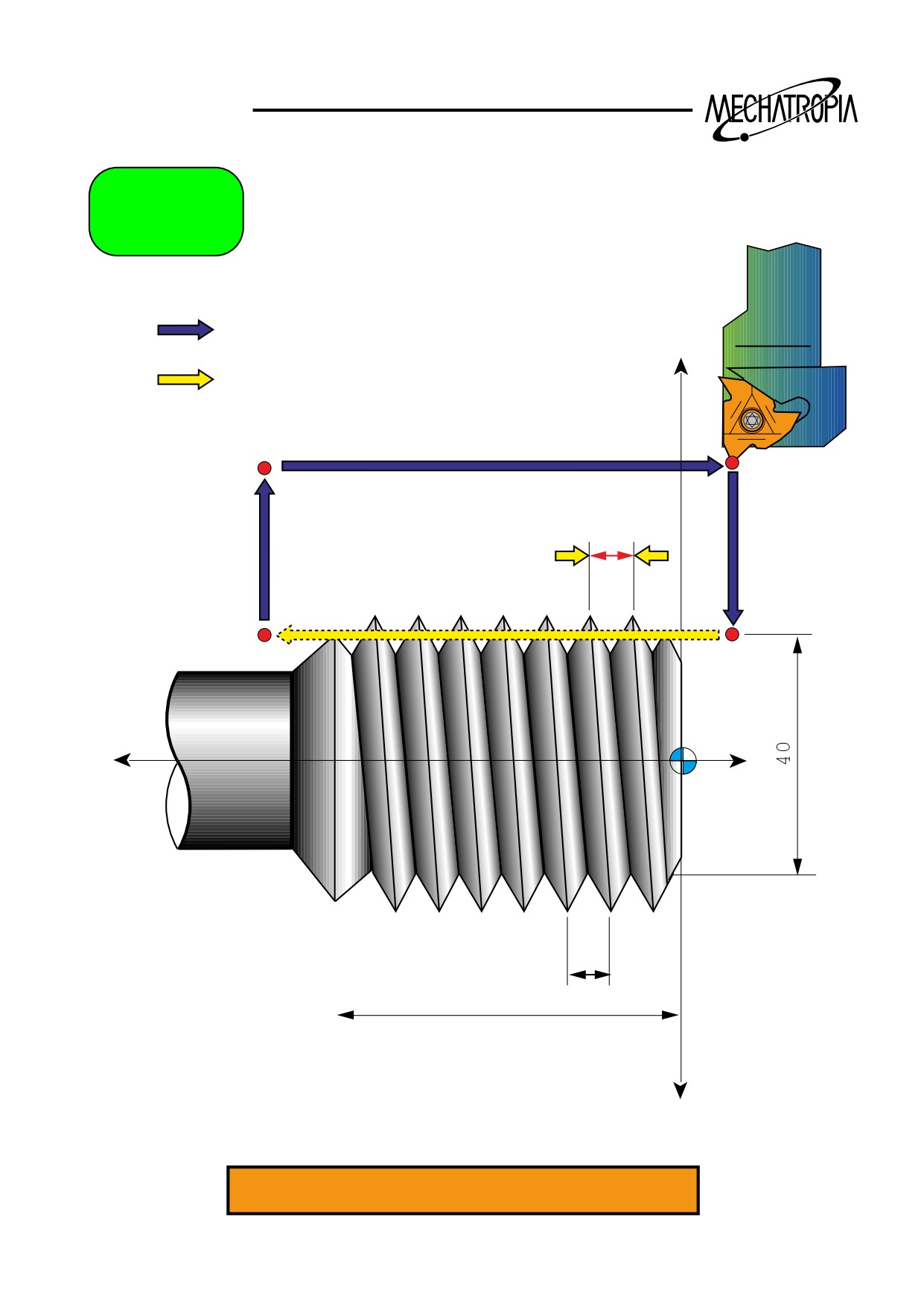
G92
G00
+X
G01
P3
P0
F
P1
P2
-Z
+Z
5
50
-X
N1234 G92 X40. Z-55. F5.
57
TRAINING
G92 Fixed cycle
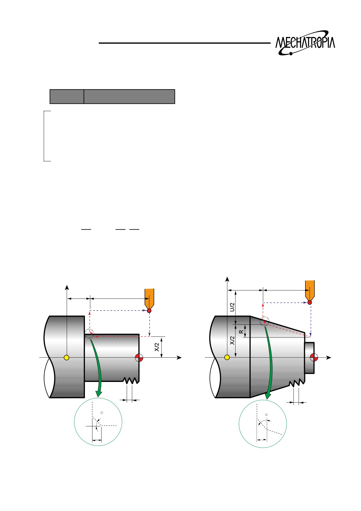
1) Single fixed cycle for cutting
FORMAT
G92 X(U) Z(W) _R_F_
X(U)
: X axis coordinate of thread process position of each time
Z(W)
: End point
R-
: When cutting form the start point to X+ direction.
R+
: When cutting from the start point to X- direction.
I/R
: Lead(pitch)
Note) Spindle override and feedrate override of cycle distance are disregarded.
G92x(U)
Z(W)
F
; Lead(L) is specified
G92x(U) _ Z(W)_ F_
;
X
X
Z
W
Z
W
4(R)
3(R)
4(R)
1(R)
3(R)
1(R)
2(F)
2(F)
Z
Z
L
L
45
R... Rapid traverse
45
F... Thread cutting specified
by F code
r
r
58