FANUC I/O Unit–MODEL A CONNECTION AND MAINTENANCE MANUAL MARMGIOMA12801E REV. F (B-61813EN/06) - page 8
B-61813E/06
MAINTENANCE
1.OVERVIEW
1 OVERVIEW
1.1
SYSTEM CONFIGURATION
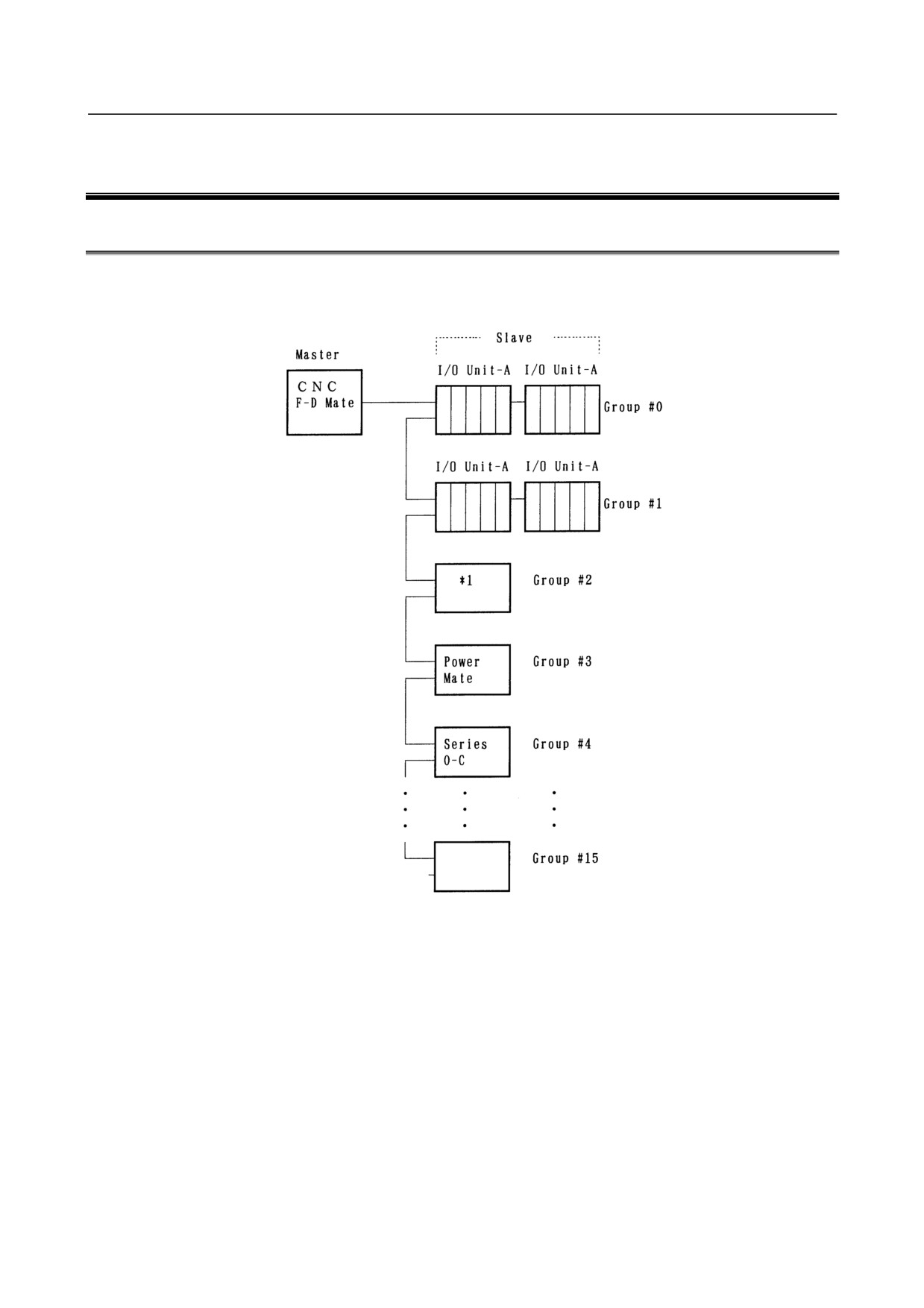
I/O Unit-A is connected to a CNC and cell controller through a high-speed serial interface, I/O Link i or I/O
Link.
(*1) Operator’s panel connection unit
(1) The I/O Link i or I/O Link consists of a master and slaves.
Master: Series0-C, Series15/16/18/20/21, Series15i/16i/18i/20i/21i/30i/31i/32i/35i/0i, Power
Mate-D/H, Power Mate i-D/H, F-D Mate
Slave: I/O Unit-A, I/O Unit-B, Power Mate, operator's panel connection unit, and Series 0-C, and so
on
(2) One I/O Link can connect to up 16 groups of slaves. If the master is not a CNC, one slave group can
contain up to 2 of I/O Unit A (2 base units). If the master is the F-D Mate, however, one group can
contain up to 4 I/O Units.
(3) One I/O Link i can connect to up to 24 slave groups.
Only one I/O Unit-A (one base) can connect to one group.
(4) I/O Link i allows no base expansion.
- 187 -
1.OVERVIEW
MAINTENANCE
B-61813E/06
1.2
I/O Unit-A CONFIGURATION
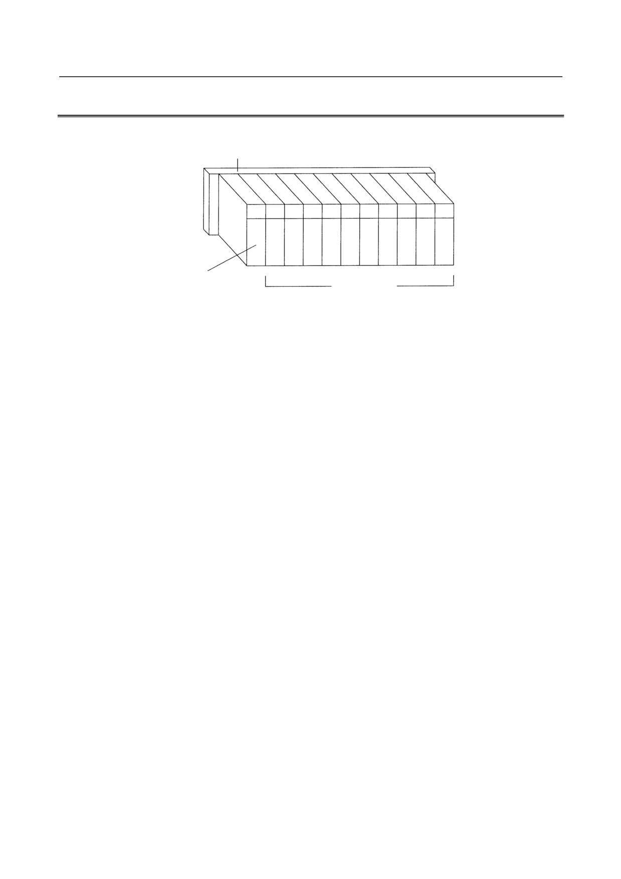
An I/O Unit-A consists of a base unit, interface module, and I/O modules.
Base unit (ABU05A, ABU10A, ABU05B, or ABU10A)
Interface module
I/O modules
(AIF01A, AIF01A2, AIF01B,
AIF02C, or AIF01D)
Interface module
(AIF01A, AIF01B, or AIF02C)
- 188 -
B-61813E/06
MAINTENANCE
1.OVERVIEW
1.3
BLOCK DIAGRAM
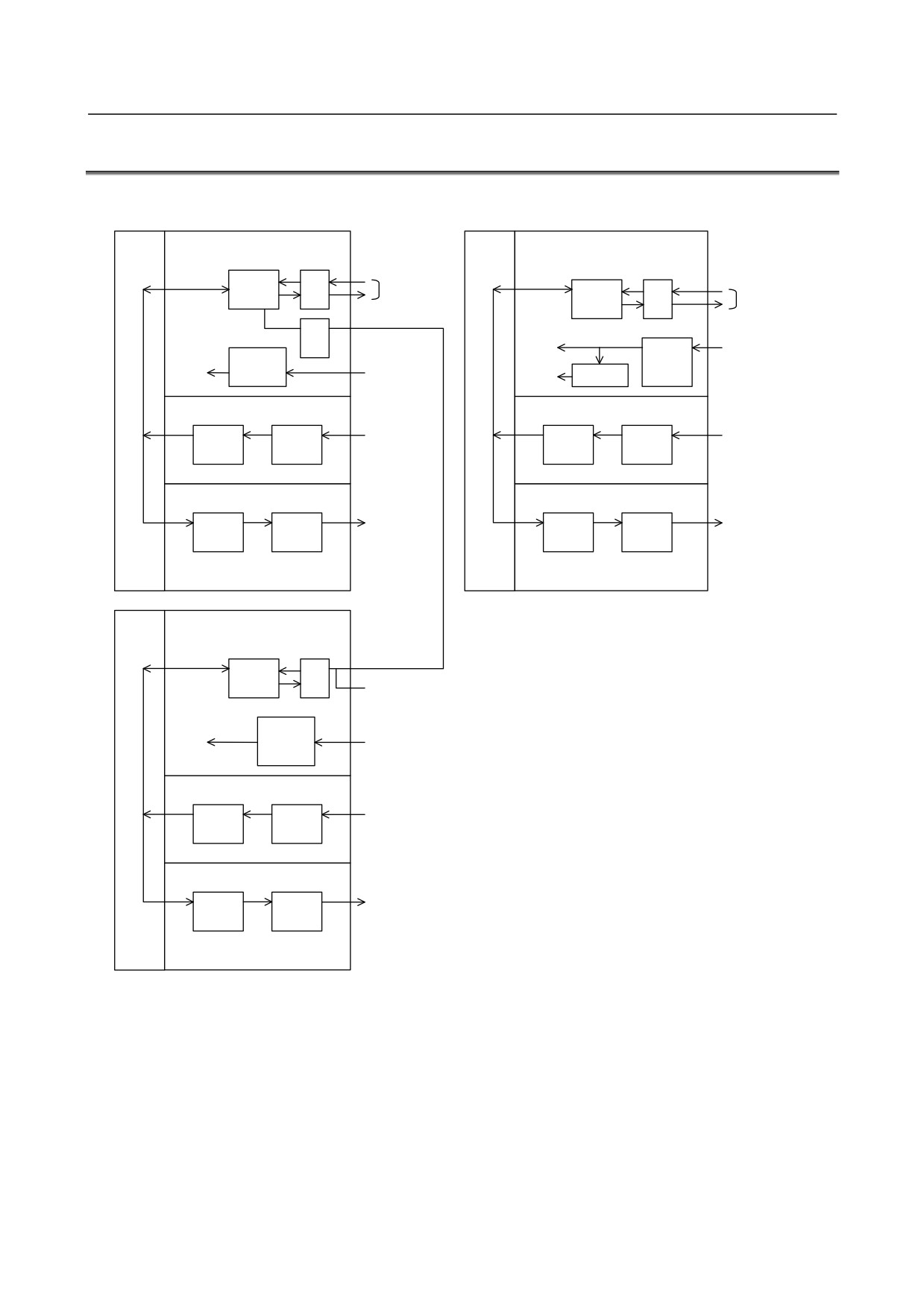
Block diagram for I/O Link
Block diagram for I/O Link i
Base
Interface module
Base
Interface module (AIF01D)
unit
(AIF01A,AIF01A2)
unit
LSI
Connection to
RV
SLIO
I/O Link
LSI
RV
Connection to
SILC
DV
I/O Link i
RV
+5V
+24VDC
DC-DC
DC-DC
converter
+5V
+24VDC
+3.3V
Regulator
Input module
Input module
Switches,
Switches,
LSI
Input
etc.
LSI
Input
etc.
ICS
circuit
ICS
circuit
Output module
Output module
Solenoids,
Solenoids,
LSI
Output
LSI
Output
ABU05A
lamps, etc.
ABU05A
lamps, etc.
OCS
circuit
OCS
circuit
ABU10A
ABU10A
ABU05B
ABU05B
ABU10B
ABU10B
Base
Interface module
unit
(AIF01B)
LSI
RV
IOCM
DV
To interface module (AIF01B)
DC-DC
+5V
+24VDC
converter
Input module
Switches,
LSI
Input
etc.
ICS
circuit
Output module
Solenoids,
LSI
Output
ABU05A
lamps, etc.
OCS
circuit
ABU10A
ABU05B
ABU10B
- 189 -
1.OVERVIEW
MAINTENANCE
B-61813E/06
1.4
I/O Unit-MODEL A CONFORMING TO UL/C-UL
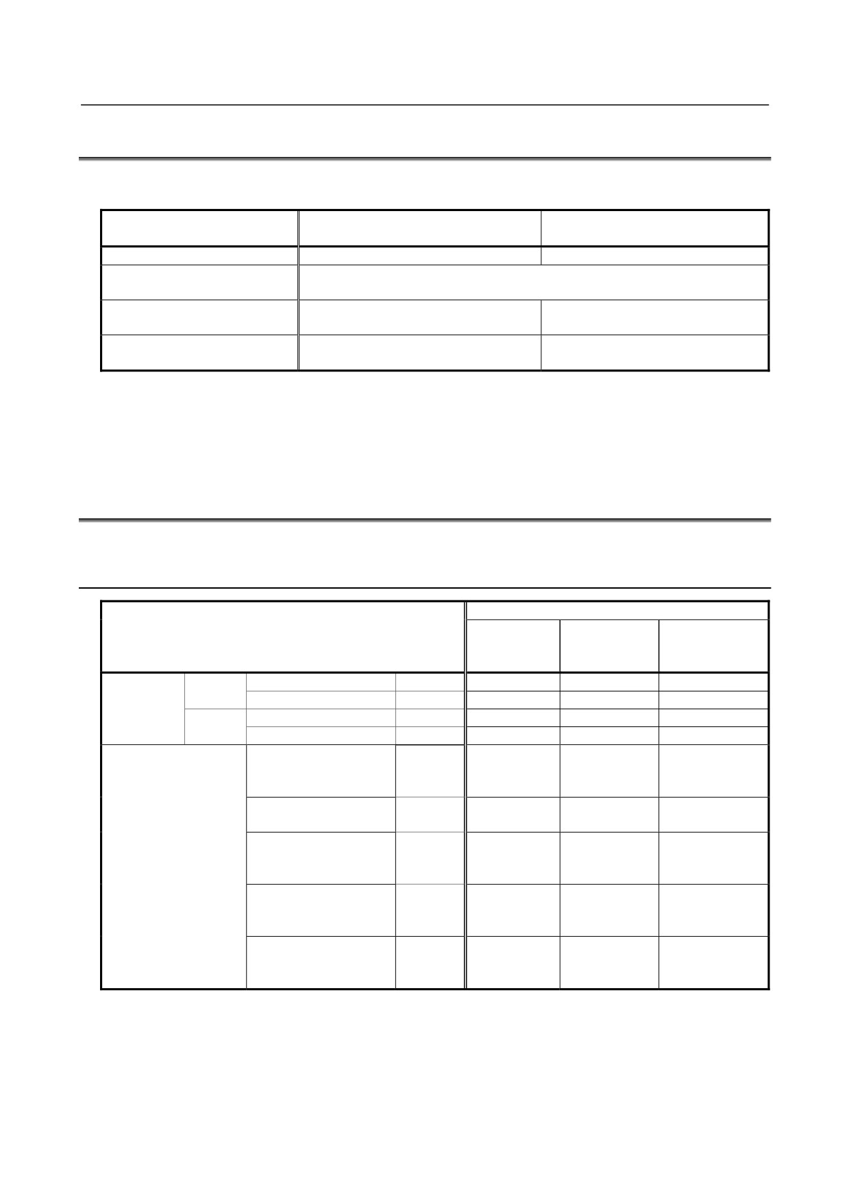
The units conforming to the UL/C-UL standard have different drawing numbers.
The following table lists the units conforming to the UL/C-UL standard and those not.
I/O Unit-MODEL A conforming to the
I/O Unit-MODEL A not conforming
UL/C-UL standard
to the UL/C-UL standard
Unit drawing number
A03B-0819-Jxxx
A03B-0807-Jxxx
Unit specification (interface,
Same specification
dimensions, and weight)
Fire retardancy: 94V-0
Plastic case
Fire retardancy: 94HB
(material less likely to burn)
The nameplates for the base unit and
Unit nameplate
The nameplates have no UL mark.
interface module bear a UL mark.
• Refer to Section 1.5, "LIST OF UNITS", in Part II for individual unit drawings.
• It is possible to use units conforming to the UL/C-UL standard and those not conforming together.
UL File No. E193565
1.5
LIST OF UNITS
1.5.1
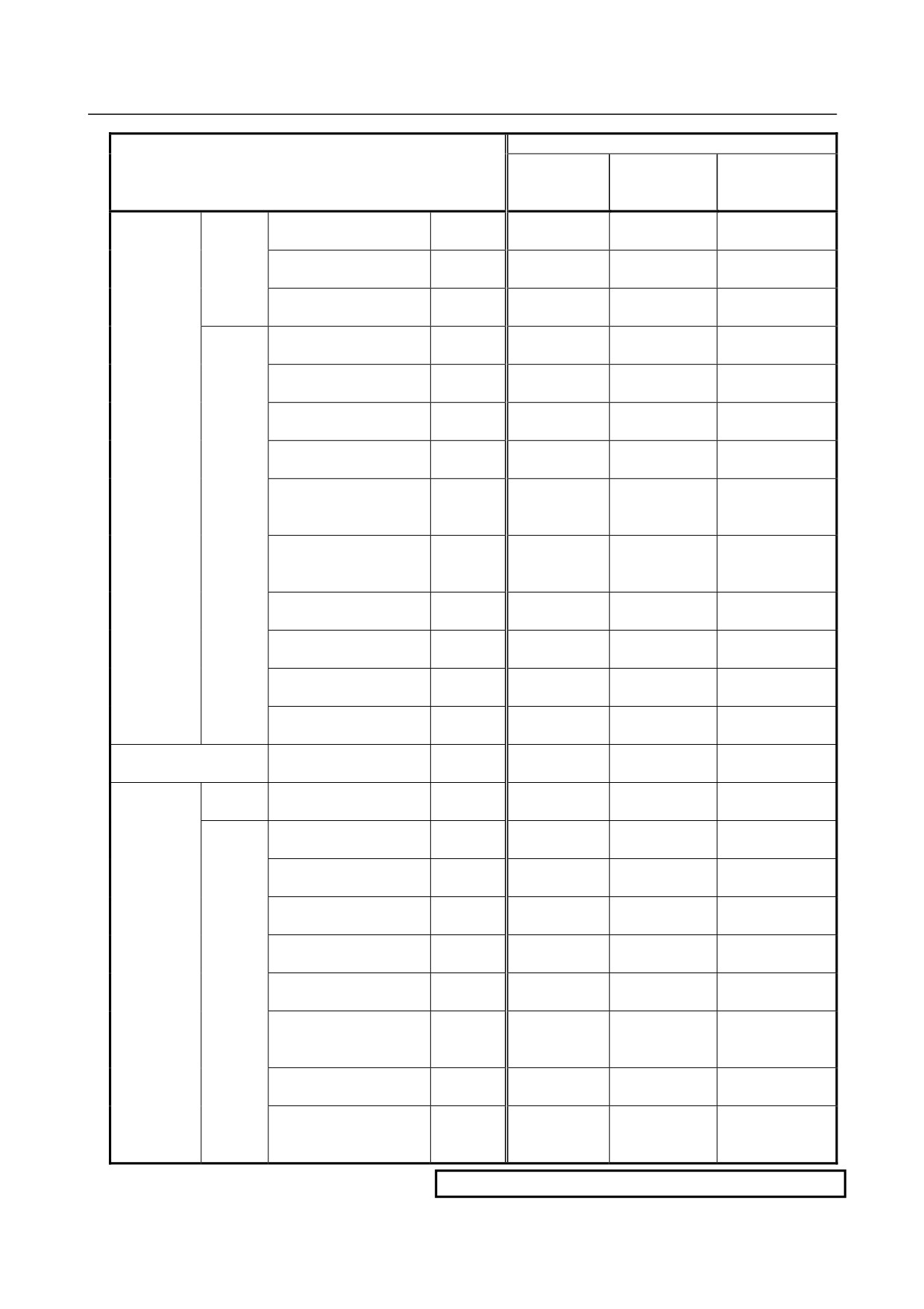
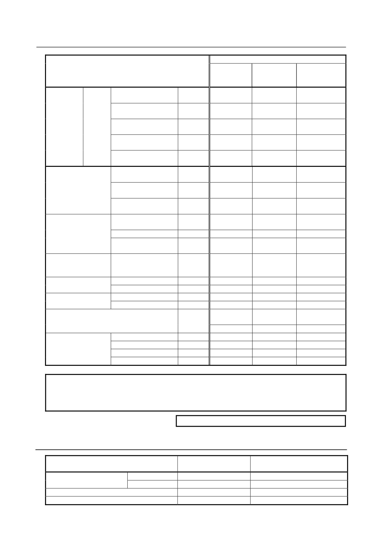
Units Conforming to UL/C-UL Standard: Ordering Information
A03B-0819-Jxxx
Unit conforming to UL/C-UL standard
Drawing number
Name
Ordering
Unit drawing
for printed circuit
information
number
board in unit
Base unit
10 slots
Horizontal type
ABU10A
A03B-0819-J001
A03B-0819-C001
A20B-9001-0040
Vertical type
ABU10B
A03B-0819-J004
A03B-0819-C004
A20B-2003-0100
5 slots
Horizontal type
ABU05A
A03B-0819-J002
A03B-0819-C002
A20B-9001-0020
Vertical type
ABU05B
A03B-0819-J003
A03B-0819-C003
A20B-2000-0510
Interface module
Power supply connector:
AIF01A
A03B-0819-J011
A03B-0819-C011
A20B-8000-0410
SORIAU JAPAN 3-pin
(former Burndy)
Power supply connector:
AIF01A2
A03B-0819-J014
A03B-0819-C014
A20B-8000-0411
Tyco Electronics 3-pin
Power supply connector:
AIF01B
A03B-0819-J012
A03B-0819-C012
A20B-8000-0420
SORIAU JAPAN 3-pin
(former Burndy)
Power supply connector:
AIF02C
A03B-0819-J013
A03B-0819-C013
A20B-8000-0710
SORIAU JAPAN 3-pin
(former Burndy)
Power supply connector:
AIF01D
A03B-0819-J015
A03B-0819-C015
A20B-8002-0780
Tyco Electronics
4 (2+2)-pin, gold-coated
- 190 -
B-61813E/06
MAINTENANCE
1.OVERVIEW
Unit conforming to UL/C-UL standard
Drawing number
Name
Ordering
Unit drawing
for printed circuit
information
number
board in unit
DC input
Non-insula
32 points, 20ms, HONDA
AID32A1
A03B-0819-J101
A03B-0819-C101
A20B-8002-0450
module
tions
50-pin
or -9000-0970
32 points, 2ms, HONDA
AID32B1
A03B-0819-J102
A03B-0819-C102
A20B-8002-0451
50-pin
or -9000-0971
32 points, 20 ms and 2 ms
AID32H1
A03B-0819-J111
A03B-0819-C111
A20B-8002-0452
intermixed, HONDA 50-pin
or -9000-0972
Insulations
16 points, NEG, 20ms,
AID16C
A03B-0819-J103
A03B-0819-C103
A20B-8002-0380
terminal block
CE:X
or -9000-0931
16 points, NEG, 2ms,
AID16K
A03B-0819-J113
A03B-0819-C113
A20B-8002-0381
terminal block
CE:X
or -9000-0932
16 points, POS, 20ms,
AID16D
A03B-0819-J104
A03B-0819-C104
A20B-8002-0370
terminal block
or -9000-0901
16 points, POS, 2ms,
AID16L
A03B-0819-J114
A03B-0819-C114
A20B-8002-0371
terminal block
or -9000-0902
16 points, POS, 20ms,
AID16DM
A03B-0819-J116
A03B-0819-C116
A20B-8002-0790
terminal block
with diagnosis functions
16 points, POS, 2ms,
AID16LM
A03B-0819-J117
A03B-0819-C117
A20B-8002-0791
terminal block
with diagnosis functions
32 points, 20ms, HONDA
AID32E1
A03B-0819-J105
A03B-0819-C105
A20B-8002-0150
50-pin
32 points, 20ms, HIROSE
AID32E2
A03B-0819-J110
A03B-0819-C110
A20B-8002-0160
50-pin
32 points, 2ms, HONDA
AID32F1
A03B-0819-J106
A03B-0819-C106
A20B-8002-0151
50-pin
32 points, 2ms, HIROSE
AID32F2
A03B-0819-J109
A03B-0819-C109
A20B-8002-0161
50-pin
AC input module
16 points, 100 to 115VAC
AIA16G
A03B-0819-J107
A03B-0819-C107
A20B-8000-0341
terminal block
DC output
Non-insula
32 points, NEG, 0.3A
AOD32A1
A03B-0819-J162
A03B-0819-C162
A20B-8002-0460
module
tions
HONDA 50-pin
CE:X
or -9001-0110
Insulations
8 points, NEG, 2A, terminal
AOD08C
A03B-0819-J151
A03B-0819-C151
A20B-8002-0420
block
CE:X
or -9001-0210
8 points, POS, 2A, terminal
AOD08D
A03B-0819-J152
A03B-0819-C152
A20B-8002-0410
block
or -9001-0220
8 points, POS, 2A, output
AOD08DP
A03B-0819-J183
A03B-0819-C183
A20B-8002-0060
protection, terminal block
16 points, NEG, 0.5A,
AOD16C
A03B-0819-J153
A03B-0819-C153
A20B-8002-0400
terminal block
CE:X
or -9000-0941
16 points, POS, 0.5A,
AOD16D
A03B-0819-J154
A03B-0819-C154
A20B-8002-0390
terminal block
or -9000-0921
16 points, POS, 0.5A,
AOD16DM
A03B-0819-J186
A03B-0819-C186
A20B-8002-0800
terminal block
with diagnosis functions
16 points, POS, 2A HONDA
AOD16D2
A03B-0819-J171
A03B-0819-C171
A20B-8002-0570
40-pin
16 points, POS, 2A
AOD16D3
A03B-0819-J185
A03B-0819-C185
A20B-8002-0520
Weidmüller 24-pin
connector
CE:X
CE marking is not supported.
- 191 -
1.OVERVIEW
MAINTENANCE
B-61813E/06
Unit conforming to UL/C-UL standard
Drawing number
Name
Ordering
Unit drawing
for printed circuit
information
number
board in unit
DC output
Insulations
16 points, POS, 0.3A, output
AOD16DP
A03B-0819-J182
A03B-0819-C182
A20B-8002-0070
module
protection, terminal block
32 points, NEG, 0.3A
AOD32C1
A03B-0819-J155
A03B-0819-C155
A20B-8002-0430
HONDA 50-pin connector
CE:X
or -9001-0070
32 points, NEG, 0.3A
AOD32C2
A03B-0819-J172
A03B-0819-C172
A20B-8002-0440
HIROSE 50-pin connector
CE:X
or -9001-0530
32 points, POS, 0.3A
AOD32D1
A03B-0819-J156
A03B-0819-C156
A20B-8000-0440
HONDA 50-pin connector
32 points, POS, 0.3A
AOD32D2
A03B-0819-J167
A03B-0819-C167
A20B-8000-0510
HIROSE 50-pin connector
AC output module
5 points, 2A, 100 to 230VAC
AOA05E
A03B-0819-J157
A03B-0819-C157
A20B-8000-0470
terminal block
8 points, 1A, 100 to 230VAC
AOA08E
A03B-0819-J158
A03B-0819-C158
A20B-8000-0480
terminal block
12 points, 0.5A, 100 to
AOA12F
A03B-0819-J159
A03B-0819-C159
A20B-8000-0321
115VAC, terminal block
Relay output module
8 points, 4A, terminal block
AOR08G
A03B-0819-J160
A03B-0819-C160
A20B-8002-0470
or -9001-0200
16 points, 2A, terminal block
AOR16G
A03B-0819-J161
A03B-0819-C161
A20B-8000-0101
16 points, 2A, HIROSE
AOR16H2
A03B-0819-J165
A03B-0819-C165
A20B-8000-0500
50-pin
DC input/output hybrid
DI: 24 points
AIO40A
A03B-0819-J200
A03B-0819-C200
A20B-9001-0240
module
DO: 16 points, NEG
CE:X
or -8002-0540
HONDA 50-pin
Analog input module
12bit, terminal block
AAD04A
A03B-0819-J051
A03B-0819-C051
A20B-8000-0450
16bit, terminal block
AAD04B
A03B-0819-J063
A03B-0819-C063
A20B-8002-0590
Analog output module
12bit, terminal block
ADA02A
A03B-0819-J052
A03B-0819-C052
A20B-8000-0460
14bit, terminal block
ADA02B
A03B-0819-J060
A03B-0819-C060
A20B-8001-0980
High-speed counter module (Note)
ACT01A
A03B-0819-J053
A03B-0819-C053
A20B-8000-0540
or -8000-0541
A03B-0819-J064
A03B-0819-C064
A20B-8000-0541
Temperature input module
Pt/JPt
ATI04A
A03B-0819-J056
A03B-0819-C056
A74L-0001-0083#PT
J/K
ATI04B
A03B-0819-J057
A03B-0819-C057
A74L-0001-0083#JK
Terminal unit for ATI04A
ATB01A
A03B-0819-J350
A03B-0819-C350
A20B-1005-0920
Terminal unit for ATI04B
ATB01B
A03B-0819-J351
A03B-0819-C351
A20B-1005-0930
NOTE
The high-speed counter module whose ordering information and unit drawing
number are, respectively, A03B-0819-J053 and A03B-0819-C053 is dedicated to
I/O Link. (See Chapter 8 of Part I, “CONNECTION”.)
CE:X
CE marking is not supported.
1.5.2
Other Units
Drawing number for printed
Name
Ordering information
circuit board in unit
Standard type
A13B-0154-B001
A20B-1004-0240
Optical adapter for I/O Link
High-speed type
A13B-0154-B004
A20B-1004-0242
Optical adapter for I/O Link i
A13B-0154-B101
A20B-2004-0600
Optical fiber junction adapter
A02B-0094-K841
-
- 192 -
B-61813E/06
MAINTENANCE
1.OVERVIEW
Drawing number for printed
Name
Ordering information
circuit board in unit
I/O Link dummy unit
A13B-0167-B001
A20B-8000-0940
2-channel I/O Link connector adapter
A20B-1007-0680
A20B-1007-0680
3-channel I/O Link connector adapter
A20B-1008-0360
A20B-1008-0360
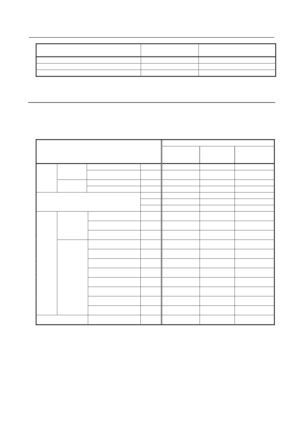
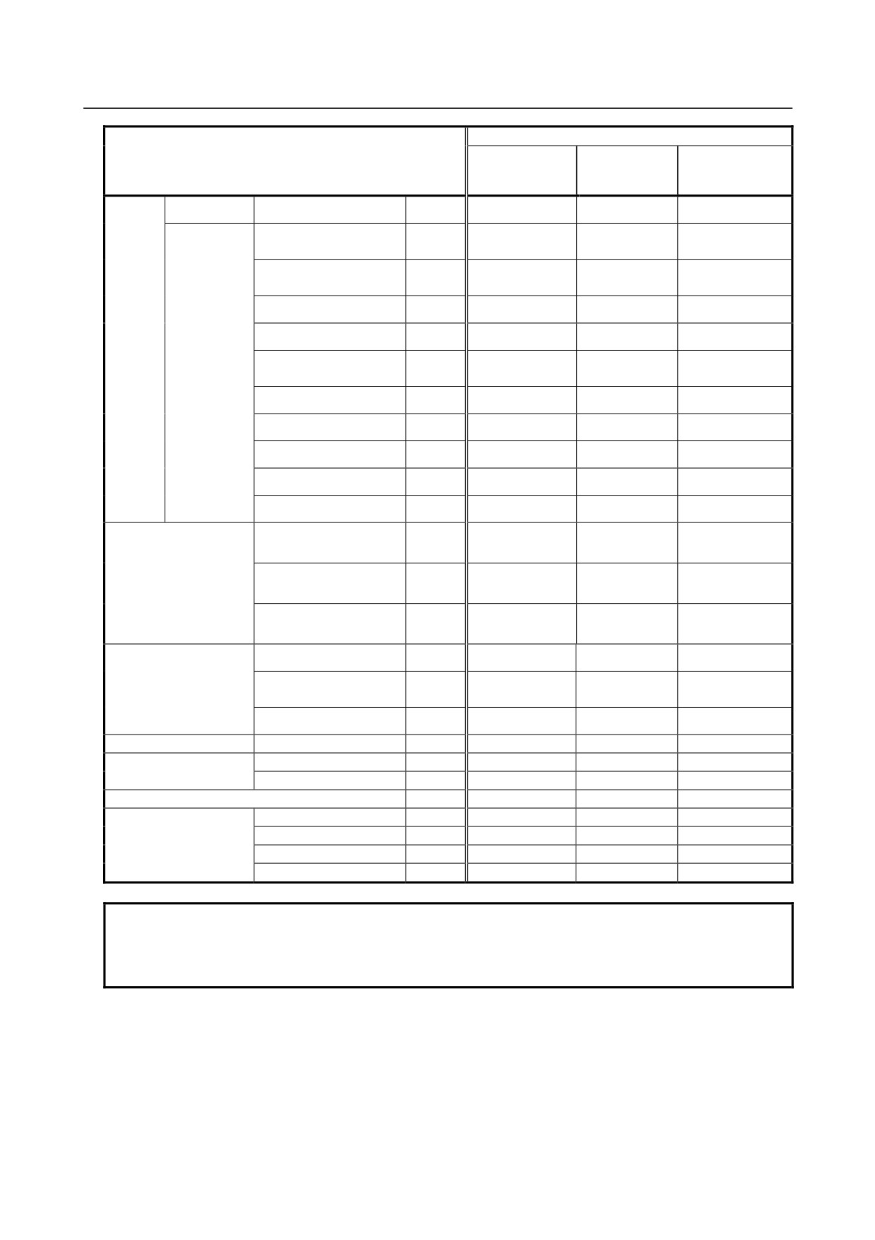
1.5.3
Early Units (Units not Conforming to UL/C-UL: Ordering
Information A03B-0807-Jxxx)
The modules listed below are those produced before the factory was UL-approved.
The module's basic performance does not differ between A03B-0807-Jxxx and A03B-0819-Jxxx.
The units with the new ordering information A03B-0819-Jxxx are housed in cases made of material less
likely to burn.
Early unit
Drawing number
Name
Early ordering
Early-unit
for printed circuit
information
drawing number
board in early unit
Base unit
10 slots
Horizontal type
ABU10A
A03B-0807-J001
A03B-0807-C001
A20B-9001-0040
A20B-2003-0100
Vertical type
ABU10B
A03B-0807-J004
A03B-0807-C004
or -2000-0550
5 slots
Horizontal type
ABU05A
A03B-0807-J002
A03B-0807-C002
A20B-9001-0020
Vertical type
ABU05B
A03B-0807-J003
A03B-0807-C003
A20B-2000-0510
Interface module
AIF01A
A03B-0807-J011
A03B-0807-C011
A20B-8000-0410
AIF01B
A03B-0807-J012
A03B-0807-C012
A20B-8000-0420
AIF02C
A03B-0807-J013
A03B-0807-C013
A20B-8000-0710
32 points, 20ms, HONDA
DC input
Non-insulations
AID32A1
A03B-0807-J101
A03B-0807-C101
A20B-9000-0970
50-pin
module
32 points, 2ms, HONDA
AID32B1
A03B-0807-J102
A03B-0807-C102
A20B-9000-0971
50-pin
32 points, 20 ms and 2 ms
AID32H1
A03B-0807-J111
A03B-0807-C111
A20B-9000-0972
intermixed, HONDA 50-pin
16 points, NEG, 20ms,
Insulations
AID16C
A03B-0807-J103
A03B-0807-C103
A20B-9000-0931
terminal block
16 points, NEG, 2ms,
AID16K
A03B-0807-J113
A03B-0807-C113
A20B-9000-0932
terminal block
16 points, POS, 20ms,
AID16D
A03B-0807-J104
A03B-0807-C104
A20B-9000-0901
terminal block
16 points, POS, 2ms,
AID16L
A03B-0807-J114
A03B-0807-C114
A20B-9000-0902
terminal block
32 points, 20ms, HONDA
A20B-8002-0150
AID32E1
A03B-0807-J105
A03B-0807-C105
50-pin
or -9001-0010
32 points, 20ms, HIROSE
A20B-8002-0160
AID32E2
A03B-0807-J110
A03B-0807-C110
50-pin
or -9001-0280
32 points, 2ms, HONDA
A20B-8002-0151
AID32F1
A03B-0807-J106
A03B-0807-C106
50-pin
or -9001-0011
32 points, 2ms, HIROSE
A20B-8002-0161
AID32F2
A03B-0807-J109
A03B-0807-C109
50-pin
or -9001-0281
16 points, 100 to 115VAC
AC input module
AIA16G
A03B-0807-J107
A03B-0807-C107
A20B-8000-0341
terminal block
- 193 -
1.OVERVIEW
MAINTENANCE
B-61813E/06
Early unit
Drawing number
Name
Early ordering
Early-unit
for printed circuit
information
drawing number
board in early unit
32 points, NEG, 0.3A,
DC output
Non-insulations
AOD32A1
A03B-0807-J162
A03B-0807-C162
A20B-9001-0110
HONDA 50-pin
module
8 points, NEG, 2A, terminal
Insulations
AOD08C
A03B-0807-J151
A03B-0807-C151
A20B-9001-0210
block
or -9000-0951
8 points, POS, 2A, terminal
AOD08D
A03B-0807-J152
A03B-0807-C152
A20B-9001-0220
block
or -9000-0911
16 points, NEG, 0.5A,
AOD16C
A03B-0807-J153
A03B-0807-C153
A20B-9000-0941
terminal block
16 points, POS, 0.5A,
AOD16D
A03B-0807-J154
A03B-0807-C154
A20B-9000-0921
terminal block
16 points, POS, 2A,
AOD16D2
A03B-0807-J171
A03B-0807-C171
A20B-8002-0570
HIROSE 40-pin
or -9001-0490
16 points, POS, 0.3A, output
AOD16DP
A03B-0807-J182
A03B-0807-C182
A20B-8002-0070
protection, terminal block
32 points, NEG, 0.3A,
AOD32C1
A03B-0807-J155
A03B-0807-C155
A20B-9001-0070
HONDA 50-pin
32 points, NEG, 0.3A,
AOD32C2
A03B-0807-J172
A03B-0807-C172
A20B-9001-0530
HIROSE 50-pin
32 points, POS, 0.3A,
AOD32D1
A03B-0807-J156
A03B-0807-C156
A20B-8000-0440
HONDA 50-pin
32 points, POS, 0.3A,
AOD32D2
A03B-0807-J167
A03B-0807-C167
A20B-8000-0510
HIROSE 50-pin
5 points, 2A, 100 to
A20B-8000-0470
AC output module
AOA05E
A03B-0807-J157
A03B-0807-C157
230VAC
or -8000-0251
terminal block
8 points, 1A, 100 to
A20B-8000-0480
AOA08E
A03B-0807-J158
A03B-0807-C158
230VAC
or -8000-0381
terminal block
12 points, 0.5A, 100 to
AOA12F
A03B-0807-J159
A03B-0807-C159
A20B-8000-0321
115VAC
terminal block
Relay output module
8 points, 4A, terminal block
AOR08G
A03B-0807-J160
A03B-0807-C160
A20B-9001-0200
or -9000-0961
16 points, 2A, terminal
AOR16G
A03B-0807-J161
A03B-0807-C161
A20B-8000-0101
block
16 points, 2A, HIROSE
AOR16H2
A03B-0807-J165
A03B-0807-C165
A20B-8000-0500
50-pin
Analog input module
12bit, terminal block
AAD04A
A03B-0807-J051
A03B-0807-C051
A20B-8000-0450
Analog output module
12bit, terminal block
ADA02A
A03B-0807-J052
A03B-0807-C052
A20B-8000-0460
14bit, terminal block
ADA02B
A03B-0807-J060
A03B-0807-C060
A20B-8001-0980
High-speed counter module (Note)
ACT01A
A03B-0807-J053
A03B-0807-C053
A20B-8000-0540
Temperature input module
Pt/JPt
ATI04A
A03B-0807-J056
A03B-0807-C056
A74L-0001-0083#PT
J/K
ATI04B
A03B-0807-J057
A03B-0807-C057
A74L-0001-0083#JK
Terminal unit for ATI04A
ATB01A
A03B-0807-J350
A03B-0807-C350
A20B-1005-0920
Terminal unit for ATI04B
ATB01B
A03B-0807-J351
A03B-0807-C351
A20B-1005-0930
NOTE
The high-speed counter module whose ordering information and unit drawing
number are, respectively, A03B-0819-J053 and A03B-0819-C053 is dedicated to
I/O Link. (See Chapter 8 of Part I, “CONNECTION”.)
- 194 -
B-61813E/06
MAINTENANCE
2.INDICATION
2 INDICATION
The interface modules and the I/O modules with up to 16 input/output points have LEDs to indicate their
states.
2.1
INTERFACE MODULE (AIF01A, AIF01A2) LED
INDICATORS
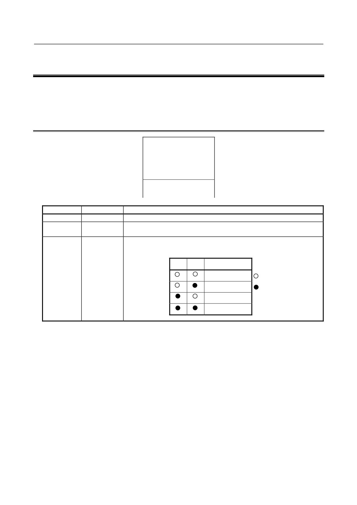
{ PWR
{ LINK
{ BA1
{ BA0
A I F 0 1 A
Marking
Name
Description
PWR
Power-on
On: The interface module is supplied with power of 24 VDC.
LINK
Link
On: The I/O Link is operating properly.
Normally, this LED lights several to ten-odd seconds after the master is turned on.
BA1
Base address
These LEDs indicate which base unit the inter-face module is transferring data with.
BA0
If a failure occurs (the LINK LED is turned on, then off), BA0 or BA1, whichever is
operating, is turned on.
BA1
BA0
Base number
Base #0
: Off
Base #1
: On
Base #2
Base #3
Failures, their causes, and required actions
(1) PWR is off.
c
Power (24 VDC) is not supplied or the supply voltage is abnormal.
⇒ Supply power of 24 VDC ± 10%.
d A The fuse in the interface module has blown.
⇒ Eliminate the cause that made the fuse to blow, then replace the fuse with a spare. (See
Chapter 3.) The following may cause the fuse to blow:
• A sum of power requirements for all input modules exceeds the rating. (Refer to Section 4.4
in Part I.)
• A voltage of +24 VDC, supplied from input module AID32A1, AID32B1 or AID32H1 to
the outside, is short-circuited to the cabinet or the like.
• The interface module or any of the I/O modules is defective.
e
An I/O module is defective.
⇒ Remove the I/O modules sequentially to pinpoint the defective one. Then, replace it with a
spare.
f
An interface module is defective.
⇒ Replace it with a spare.
- 195 -
2.INDICATION
MAINTENANCE
B-61813E/06
(2) LINK has never been turned on since power is supplied.
c
If PWR is off, go to item 1).
d
The attempted power turn-on sequence was incorrect.
⇒ The slaves (I/O Unit-A, Power Mate, Series 0, etc.) must be supplied with power at the same
time or before the master (CNC or F-D Mate) is supplied with power. (Refer to Section 4.2
in Part I.)
If an attempt is made to supply power to a slave on an interface module after the master is
turned on, LINK on the interface module is not turned on provided that the interface module
corresponds to that slave or to any slave ahead of that slave (one on the far side with respect
to the master).
e
I/O Link cables are broken or short-circuited.
⇒ With reference to Note below, check the cables, and take an appropriate action.
f
Any device on the I/O Link is defective.
⇒ With reference to Note below, find a defective device, and take an appropriate action. If an
I/O Unit seems to be defective, replace interface module with a spare.
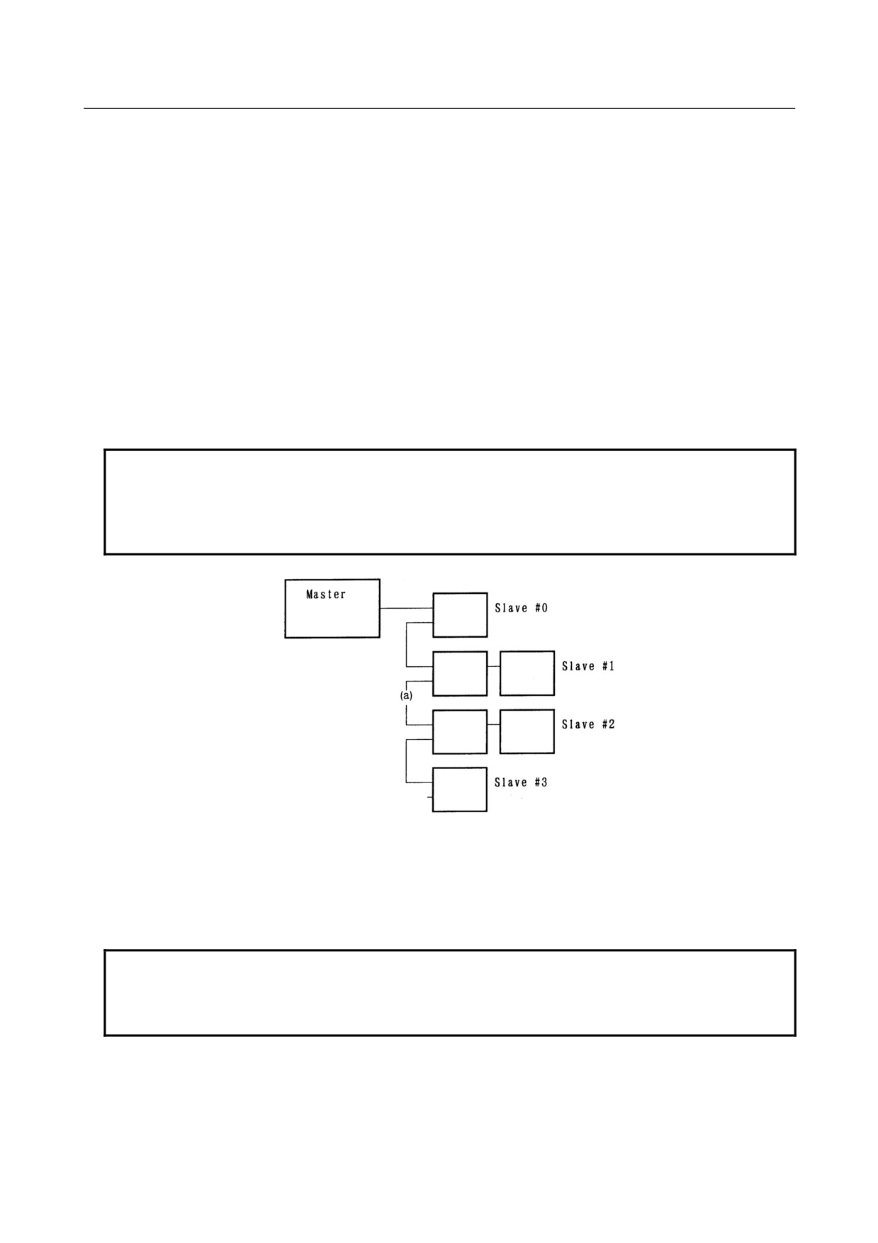
NOTE
How to pinpoint a failure in the I/O Link in event of items d to f .
Check the LEDs on the master to find out which group contains slaves whose I/O
Link is established with the master. (Refer to the maintenance manual for the
master.)
For example, if the master is linked to slaves (slave #0 and #1) that belong to separate
groups, the timing of turning on slave #2 is bad, the cable is broken or short-circuited at
point (a), slave #2 is defective.
If the master is not linked to any slave, the master may be defective.
NOTE
Some i series CNC models check the number of I/O Link slaves. If there is a group
that is not recognized, I/O Link is not established with all groups.
Recognized groups can be checked on the PMC diagnosis screen of each CNC.
(3) LINK is turned on once, then off.
c
One of the devices on the I/O Link is turned off.
⇒ Turn off all devices, then turn them on.
- 196 -
B-61813E/06
MAINTENANCE
2.INDICATION
d The DI/DO assignment for the master is invalid.
⇒ When I/O Unit bases 1 to 3 (units under control of interface module AIF01B) are not
connected, if DI/DO units are assigned to these bases, LINK is turned on, but turned off
immediately.
Correct the DI/DO assignment.
e
The I/O Link cable is broken or short-circuited.
⇒ Check the cable, and take an appropriate action.
f
Any device on the I/O Link is defective.
⇒ With reference to the maintenance manual for the master, find a defective device, and take
an appropriate action. If an I/O Unit seems defective, replace the interface module (AIF01A,
AIF01A2, or AIF01B) installed in the base unit indicated by BA1 or BA0.
2.2
INTERFACE MODULE (AIF01B) LED INDICATORS
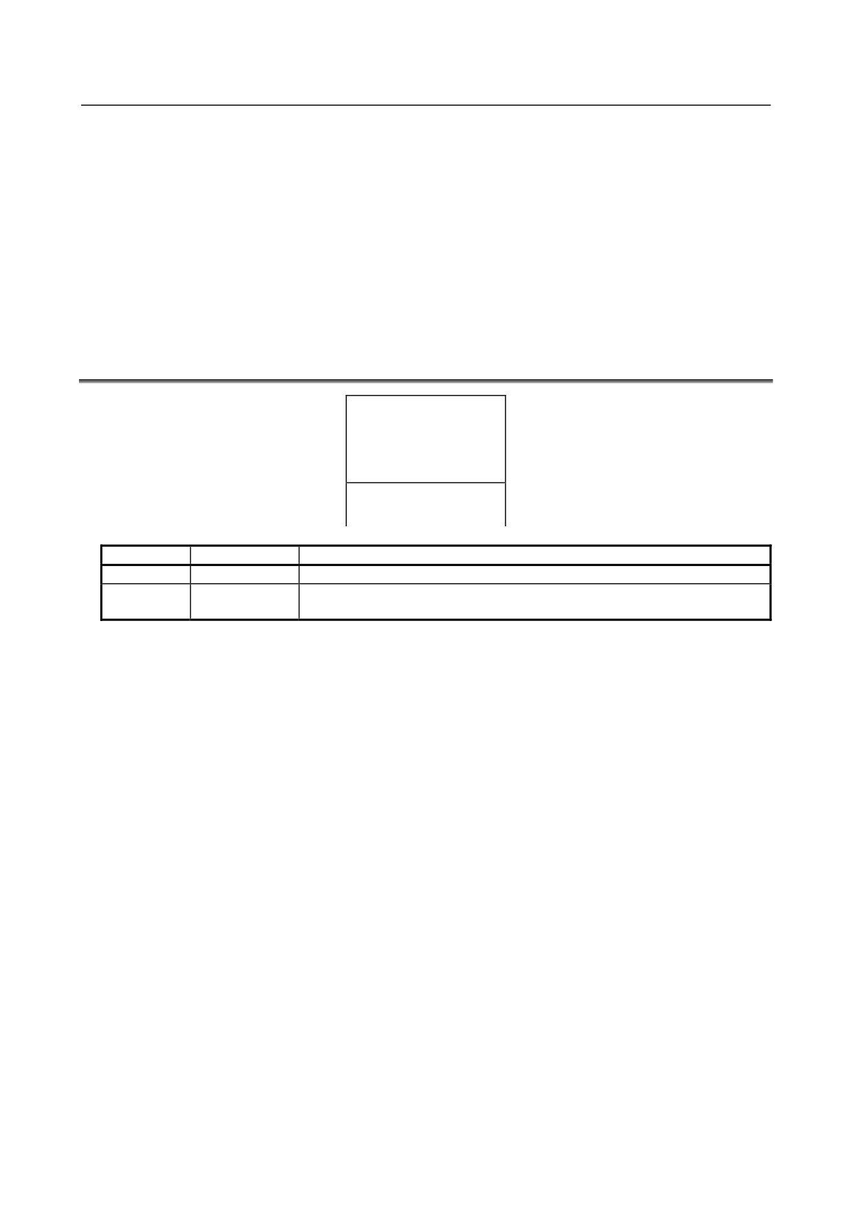
{ PWR
{ LINK
A I F 0 1 B
Marking
Name
Description
PWR
Power-on
On: The interface module is supplied with power of 24 VDC.
LINK
Link
On: The I/O Link is operating properly.
Normally, this LED lights several to ten-odd seconds after the master is turned on.
Failures, their causes, and required actions
(1) PWR is off.
c
Power (24 VDC) is not supplied or the supply voltage is abnormal.
⇒ Supply power of 24 VDC ±10%.
d The fuse in the interface module has blown.
⇒ Eliminate the cause that made the fuse to blow, then replace the fuse with a spare. (See
Chapter 3.) The following may cause the fuse to blow:
• A sum of power requirements for all input modules exceeds the rating. (Refer to Section 4.4
in Part I.)
• A voltage of +24 VDC, supplied from input module AID32A1, AID32B1 or AID32H1 to
the outside, is short-circuited to the cabinet or the like.
• The interface module or any of the I/O modules is defective.
e
An I/O module is defective.
⇒ Remove the I/O modules sequentially to pinpoint the defective one. Then, replace it with a
spare.
f
An interface module is defective.
⇒ Replace it with a spare.
(2) LINK has never been turned on since power is supplied.
c
If PWR is off, go to item 1).
d
If LINK on the AIF01A or AIF01A2 in the same group is off, go to Section 2.1.
e
The signal cable between I/O Units in the same group is broken or short-circuited.
⇒ Check the cable, and take an appropriate action.
f
An interface module is defective.
⇒ Replace it with a spare.
- 197 -
2.INDICATION
MAINTENANCE
B-61813E/06
(3) LINK is turned on once, then turned off.
c
See section 2.1.
2.3
INTERFACE MODULE (AIF02C) LED INDICATORS
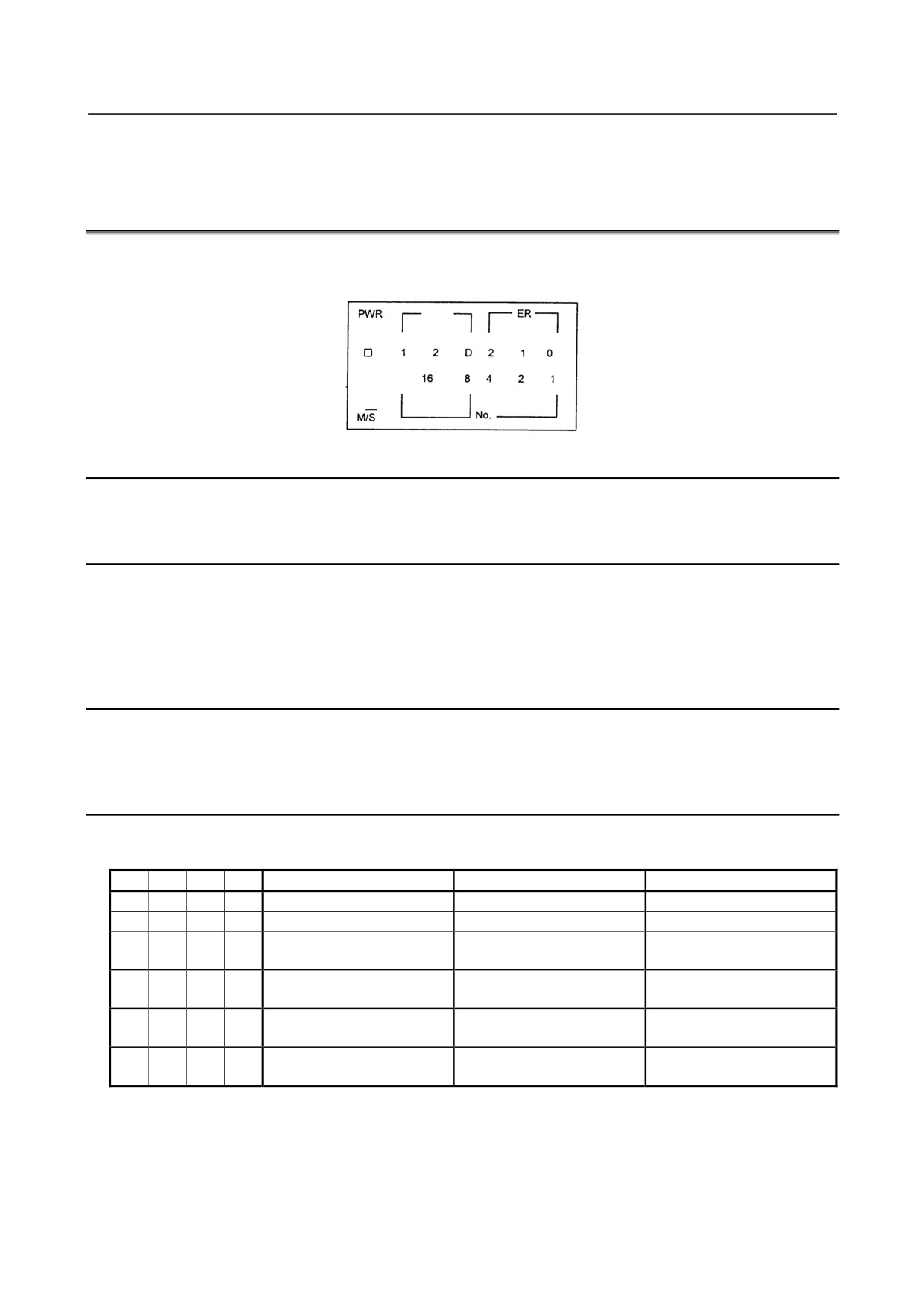
The LED indicator panel of the AIF02C is shown below. Each of its components are described in the
following paragraphs.
LNK
M
2.3.1
PWR Indicator
This LED lights when the power is switched on.
2.3.2
LNK Indicators
(1) LNK-1
: Lights when the I/O Link for the I/O Unit-A is operating normally.
(2) LNK-2
: Lights when the I/O Link for the I/O Unit-B is operating normally.
(3) LNK-D
: Lights when the distributed link with the I/O Unit-B is operating normally. (The indicator
dims if only a few base units are connected.)
2.3.3
ER Indicators
An ER indicator lights if an error occurs on the distributed link.
See the tables on the next subsection for details.
2.3.4
LED Indicators
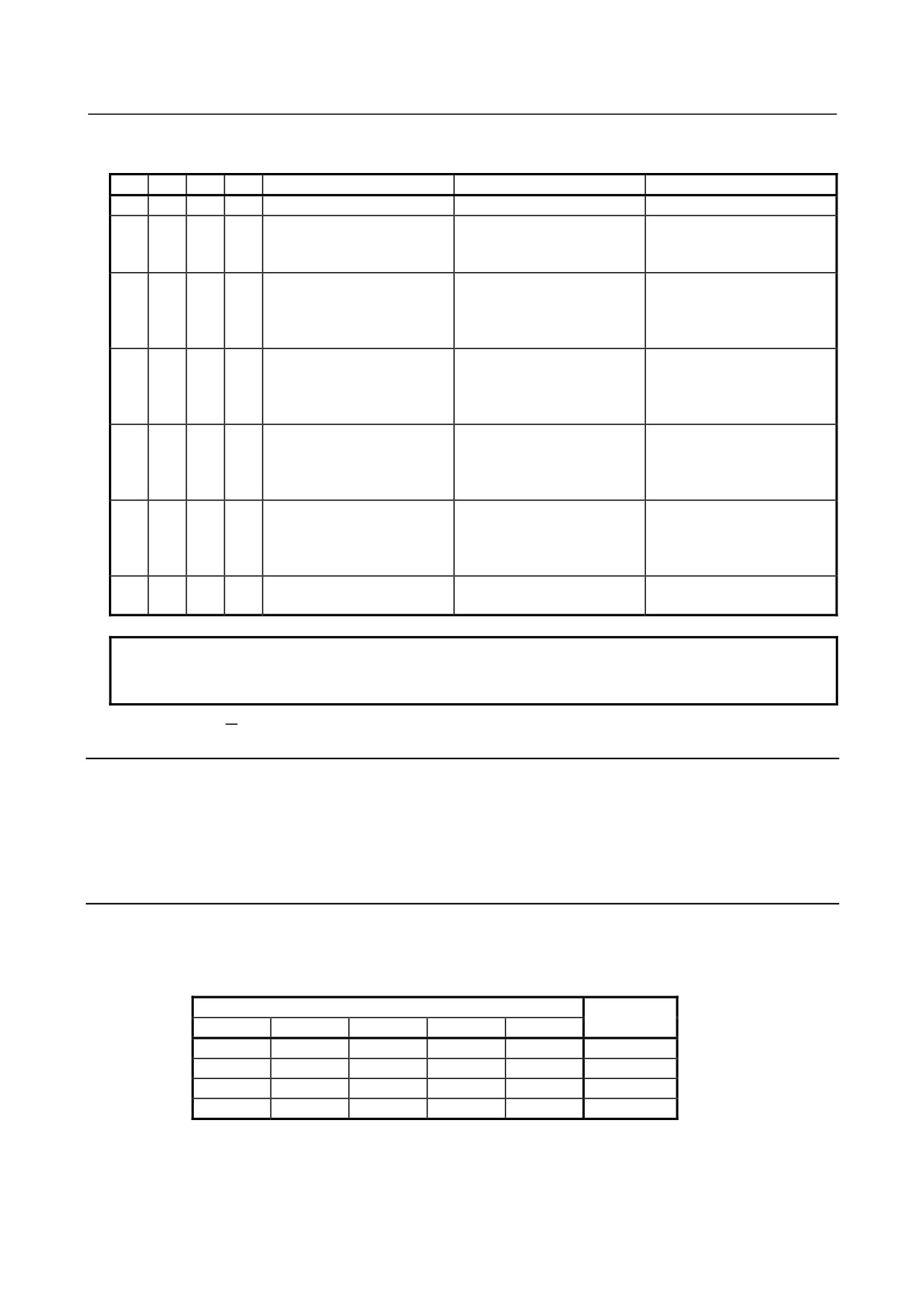
(1) When the unit No. (1 to 16) is off (o-on and ×-off)
M/S
ER2
ER1
ER0
Error
Description
Major cause of error
{
×
×
{
Interface unit peripheral error
The interface unit is abnormal.
Interface unit failure
{
×
{
×
Interface unit RAM parity error
The interface unit is abnormal.
Interface unit failure
{
{
×
×
I/O Link error reception
An error has occurred in a unit
Failure in a unit connected to
connected to the I/O Link.
the I/O Link
{
{
×
{
I/O Link framing error
The I/O Link communication
-
end signal is abnormal.
{
{
{
×
I/O Link CRC error
I/O Link communication data
-
is abnormal.
{
{
{
{
Interface unit watchdog timer
Communication from the I/O
-
error
Link host has stopped.
- 198 -
B-61813E/06
MAINTENANCE
2.INDICATION
(2) When the unit No. (1 to 16) is on (o-on and ×-off)
M/S
ER2
ER1
ER0
Error
Description
Major cause of error
×
×
×
{
Basic unit peripheral error
The basic unit is abnormal.
Basic unit failure
{
×
{
×
Basic unit number error
A unit with an invalid unit
-
number has responded to the
interface unit.
×
×
{
{
Basic unit reception data
The number of communication
Two or more units have the
count error
bytes has exceeded four.
same unit number, or the unit
of interest is not provided with
a terminating resistor.
×{
{
×
×
Basic unit framing error
The communication end signal
Two or more units have the
(*1)
is abnormal.
same unit number, or the unit
of interest is not provided with
a terminating resistor.
×{
{
×
{
Basic unit DMI error
The communication waveform
Two or more units have the
(*1)
has been distorted.
same unit number, or the unit
of interest is not provided with
a terminating resistor.
×{
{
{
×
Basic unit CRC error
The communication data is
Two or more units have the
(*1)
abnormal.
same unit number, or the unit
of interest is not provided with
a terminating resistor.
×
{
{
{
Basic unit watchdog timer
Communication with the
-
error
interface unit has stopped.
NOTE (*1)
If M/S lights, it means that the interface module (AIF02C) detected the error.
If it does not light, it means that the basic unit of the I/O Unit-B detected the error.
2.3.5
M/S Indicator
If an error occurs on a distributed link, the M/S indicator indicates whether the error was detected in the
interface module or basic error side.
On: The error has been detected on the interface module side.
Off: The error has been detected on the basic unit side.
2.3.6
No. Indicators
If an error occurs on a distributed link, the No. indicators indicate the basic unit No. where the error is
detected. The sum of the values for which a lamp lights corresponds to the basic unit No.
Example)
No.
Unit No.
16
8
4
2
1
×
×
×
×
{
1
{ -On
×
×
{
×
{
5
×-Off
×
{
×
{
×
10
{
×
{
×
×
20
- 199 -
2.INDICATION
MAINTENANCE
B-61813E/06
2.4
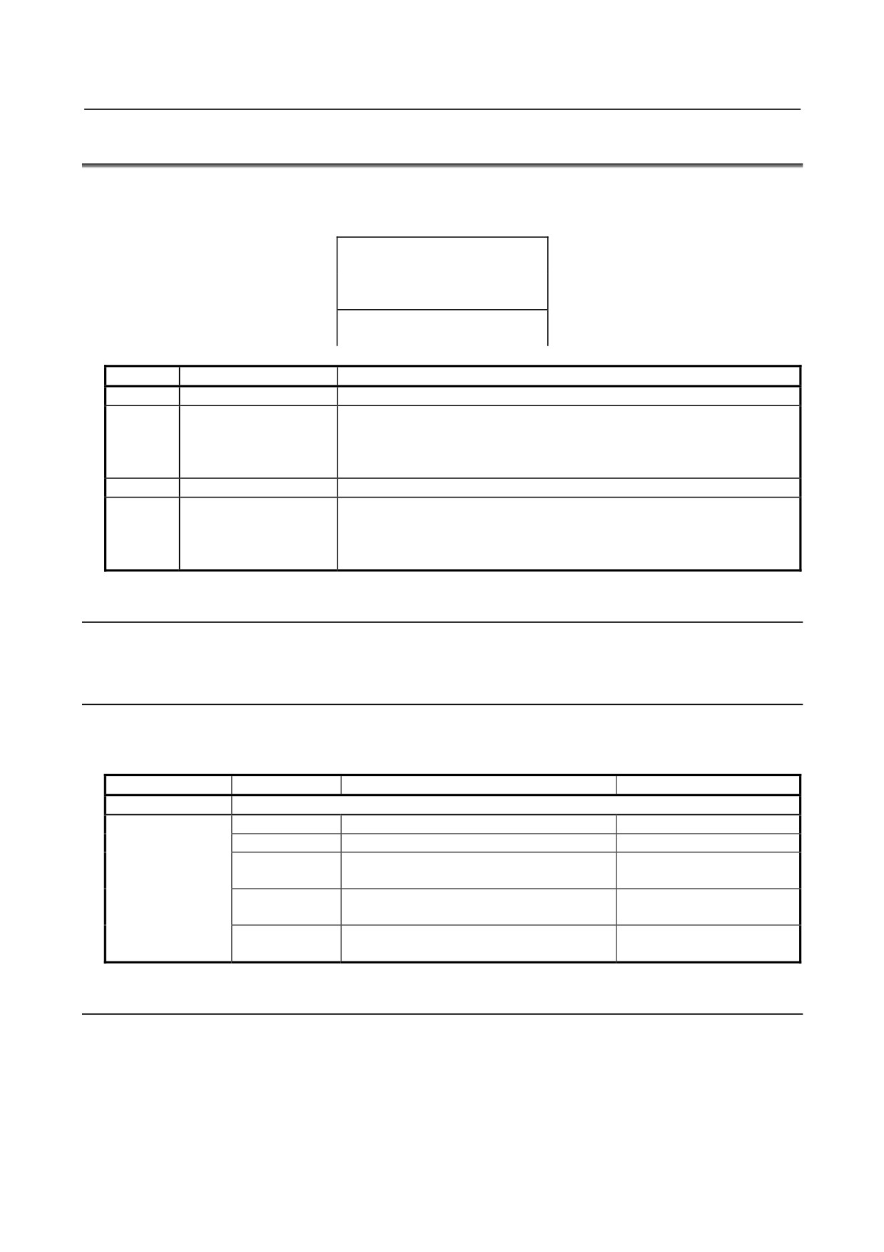
INTERFACE MODULE (AIF01D) LED INDICATORS
The LED indicator panel of the AIF01D is shown below. Each of its components are described in the
following paragraphs.
FUSE○
○PWR
ALM○
○LINK
AIF01D
Marking
Name
Description
PWR
Power-on
On: The interface module is supplied with power of 24 VDC.
LINK
The states of the LED (whether the LED stays on, blinks, or stays off) indicate
the communication states of the group.
Link
See Subsection 2.4.2, “LINK Indicator” for details of the indication by the
LED.
FUSE
Fuse
On : The fuse of the group has blown.
ALM
The states of the LED (whether the LED stays on, blinks, or stays off) indicate
the types of alarms that have occurred in the group.
Alarm
See Subsection 2.4.4, “ALM Indicator” for details of the alarms indicated by
the LED.
2.4.1
PWR Indicator
The PWR indicator lights when the power is on.
2.4.2
LINK Indicator
The indications of the LINK LED indicator vary depending on what the present operation mode is and
whether communication is in progress, as listed below.
Operation mode
LED indication
Meaning
Remarks
I/O Link
The indicator is unusable because it is dedicated to I/O Link i.
I/O Link i
Off
Power-off
On
Power-on
Blinks (1:1)
Communication in progress
On = Approx. 0.5 sec
Standard
Off = Approx. 0.5 sec
Blinks (3:1)
Communication in progress
On = Approx. 1.5 sec
Dual check safety in use
Off = Approx. 0.5 sec
Blinks
Communication not in progress
On = Approx. 0.25 sec
(high-speed1:1)
Watchdog alarm occurrence
Off = Approx. 0.25 sec
2.4.3
FUSE Indicator
The FUSE indicator lights when a fuse has blown.
After removing the cause of the blown fuse, replace the fuse. (See Chapter 3.)
- 200 -
B-61813E/06
MAINTENANCE
2.INDICATION
2.4.4
ALM Indicator
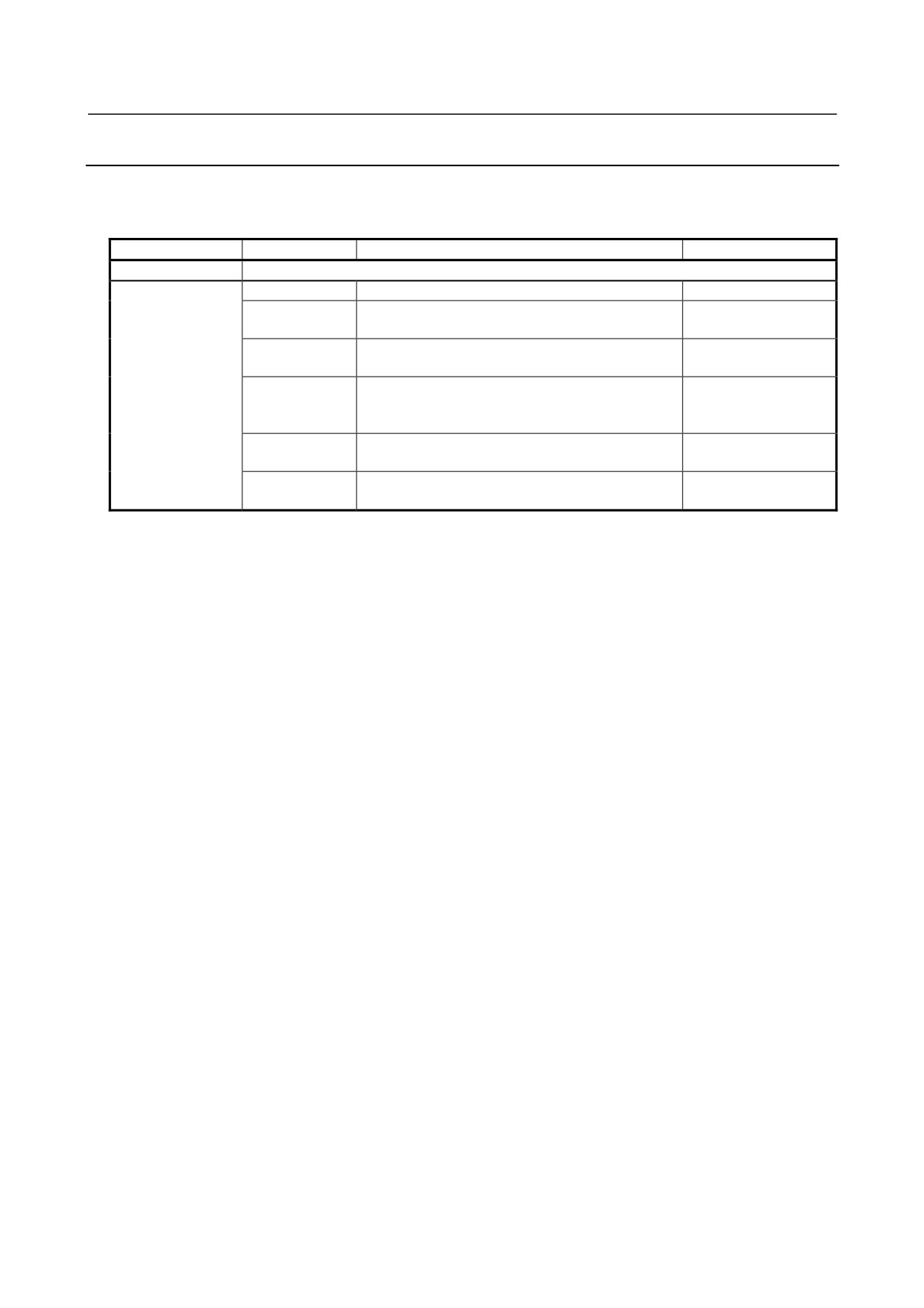
The indications of the ALM LED indicator vary depending on what the present operation mode is and the
types of alarms that have occurred, as listed below.
Operation mode
LED indication
Meaning
Remarks
I/O Link
The indicator is unusable because it is dedicated to I/O Link i.
I/O Link i
Off
Normal state or power is OFF.
On
The parity alarm, external input alarm, or dual
check safety alarm has occurred.
Blinks (1:1)
A broken wire has occurred between the group of
On = Approx. 0.5 sec
interest and the subsequent group.
Off = Approx. 0.5 sec
Blinks (3:1)
A power failure (such as a power moment drop)
On = Approx. 1.5 sec
has occurred in the group subsequent to the group
Off = Approx. 0.5 sec
of interest.
Blinks (1:3)
The status alarm has occurred.
On = Approx. 0.5 sec
Off = Approx. 1.5 sec
Blinks
An alarm has occurred due to a command from the
On = Approx. 0.25 sec
(high-speed1:1)
master.
Off = Approx. 0.25 sec
- 201 -
2.INDICATION
MAINTENANCE
B-61813E/06
2.5
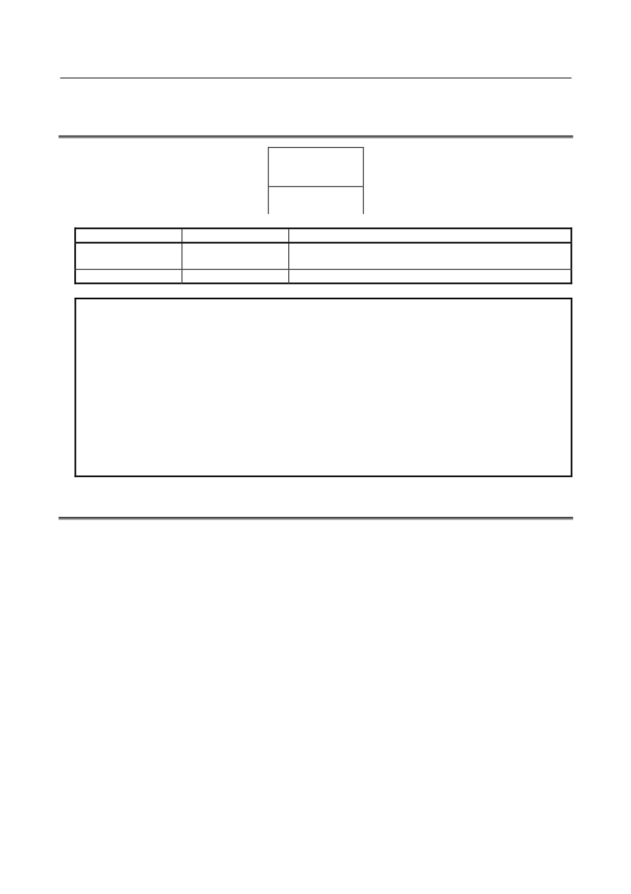
LED INDICATORS ON THE INPUT/OUTPUT MODULES
(HAVING 16 OR FEWER INPUT/OUTPUT POINTS)
A01234567
F
B01234567
Label
Name
Description
A0 to 7
Input/output indicator
On : The corresponding input or output is on.
B0 to 7
F
Fuse alarm
On : A fuse incorporated in the output module has blown.
NOTE
1 For the output protection module (AOD08DP or AOD16DP), the LED lights when
the protection function is operating.
For details, see the page on which the specifications of the each module are
described.
2 For the output module with a diagnosis function (AOD16DM), the LED lights when
the protection function is operating.
For details, see the page on which the specifications of this module are described.
3 For the input modules with a diagnosis function (AID16DM and AID16LM), the
LED lights if a common voltage moment drop occurs.
For details, see the page on which the specifications of each module are
described.
2.6
LED DISPLAY OF THE HIGH-SPEED COUNTER MODULE
Refer to Subsection 8.2.7 in the Part I, “Connection.”
- 202 -
B-61813E/06
MAINTENANCE
3.FUSES
3 FUSES
The modules listed below have built-in fuses. If a fuse blows, remove the cause, then replace the fuse with
a spare.
Module
Indication
Rating
Fuse specification
Interface module AIF01A
PWR is off.
3.2A
A60L-0001-0290#LM32
Interface module AIF01A2
PWR is off.
3.2A
A60L-0001-0290#LM32
Interface module AIF01B
PWR is off.
3.2A
A60L-0001-0290#LM32
Interface module AIF02C
PWR is off.
3.2A
A60L-0001-0290#LM32
Interface module AIF01D
PWR is off.
3.2A
A60L-0001-0290#LM32
FUSE is on.
Output module with 8 DC points AOD08C
F is on.
5A
A60L-0001-0260#5R00
Output module with 8 DC points AOD08D
F is on.
5A
A60L-0001-0260#5R00
Output module with 16 DC points AOD08D3
F is on.
5A
A60L-0001-0046#5.0
Output module with 5 AC points AOA05E
F is on.
3.15A
A60L-0001-0276#3.15
Output module with 8 AC points AOA08E
F is on.
3.15A
A60L-0001-0276#3.15
Output module with 12 AC points AOA12F
F is on.
3.15A
A60L-0001-0276#3.15
The fuses are on the PC boards in the modules.
- 203 -
4.REMOVING PC BOARDS
MAINTENANCE
B-61813E/06
4 REMOVING PC BOARDS
4.1
HOW TO REMOVE TERMINAL BOARD-TYPE I/O MODULE
PC BOARDS
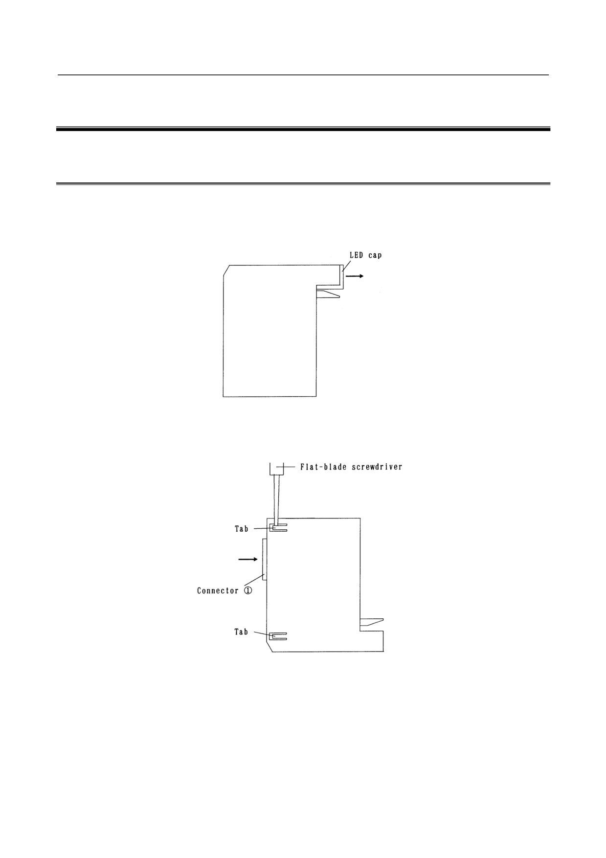
c
Remove the terminal board. (Refer to 4.5 in Part I.)
d Pull the LED cap in the direction of the arrow to remove it.
e
While pressing connector c in the direction of the arrow, raise the tabs (two) on the module case with
a flat-blade screwdriver.
- 204 -
B-61813E/06
MAINTENANCE
4.REMOVING PC BOARDS
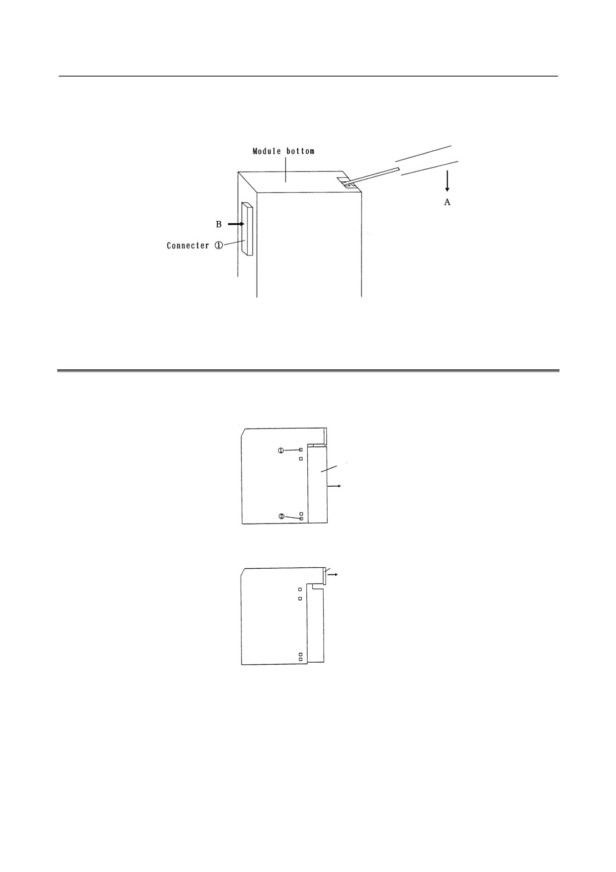
f
Put the tip of a flat-blade screwdriver into the gap between the module case and terminal board
connector, as shown below. While pressing the screwdriver in the direction of arrow A, push
connector c in the direction of arrow B, and the PC board will come out.
4.2
HOW TO REMOVE INTERFACE AND CONNECTOR-TYPE
I/O MODULE PC BOARDS
c
While pulling the cover in the direction of the arrow, press points c and d
(on each side) with a
flat-blade screwdriver to remove the cover.
Cover
d Pull the LED cap in the direction of the arrow to remove it.
LED Cap
- 205 -
4.REMOVING PC BOARDS
MAINTENANCE
B-61813E/06
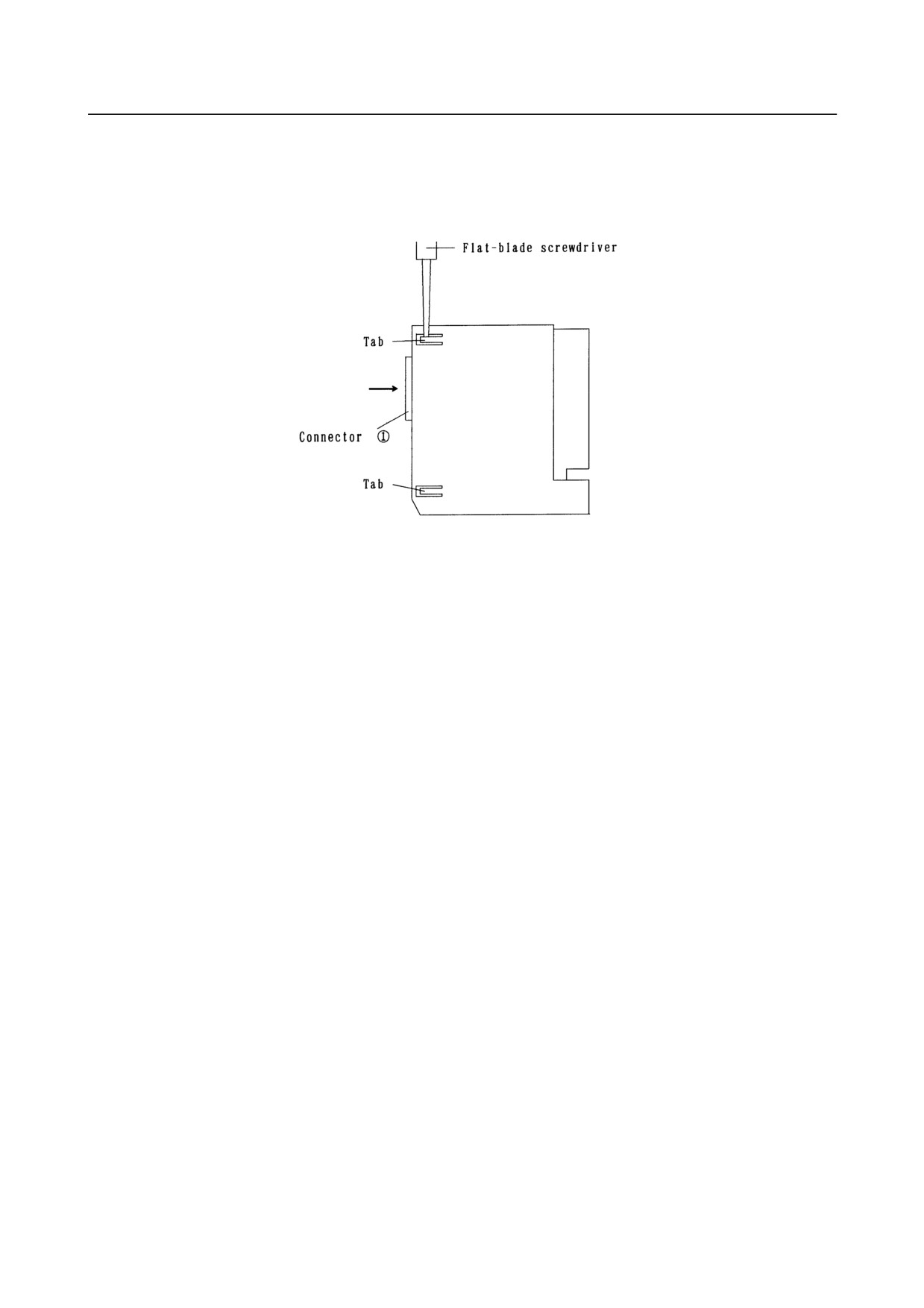
e
While pressing connector c in the direction of the arrow, raise the tabs (2 places for connector-type
input/output modules and the AIF01D and 4 places for interface modules other than the AIF01D (both
sides)) with a flat-screwdriver, then push connector c in the direction of the arrow, and e PC board
will come out.
- 206 -