FANUC I/O Unit–MODEL A CONNECTION AND MAINTENANCE MANUAL MARMGIOMA12801E REV. F (B-61813EN/06) - page 7
B-61813E/06
CONNECTION
9.TEMPERATURE INPUT MODULE
(3)
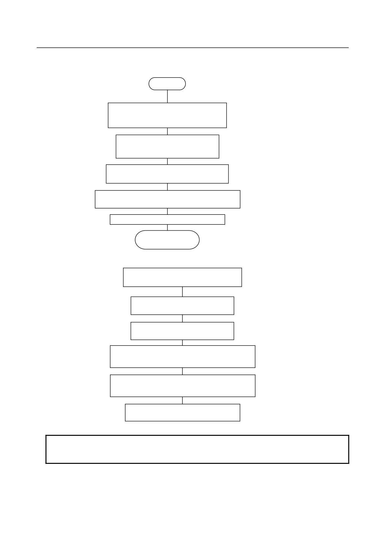
4-channel manual measurement mode
(a) Flowchart
START
* Check that NC READY
(DO16) and DO19 are "0".
Specify the module type (DO17).
0 : Thermocouple module
1 : Thermoresistance module
Specify the sensor type (DO18).
0 : Pt/K
1 : JPt/J
Set the number of channels bit (DO24) to
"1".
Set the 4-channel mode specification bit (DO25)
to "1".
Set NC READY (DO16) to "1".
Now ready to
measure.
* Reading CH1 and CH2 data
Ensure that the READ request bit
(DO22) is set to "0".
Reset the channel select bit
(DO26) to "0".
Set the READ request bit (DO22)
(Note)
to "1".
When CH1 data READY (DI14 of input signal) is
set to "1", input signals DI00 to DI12 represent
CH1 data.
When CH2 data READY (DI30 of input signal)
becomes "1", input signals DI16 to DI28
represent CH2 data.
Reset the READ request bit (DO22) to
"0".
NOTE
After setting NC READY to "1", wait for one second, and then set the READ
request to "1".
- 155 -
9.TEMPERATURE INPUT MODULE CONNECTION
B-61813E/06
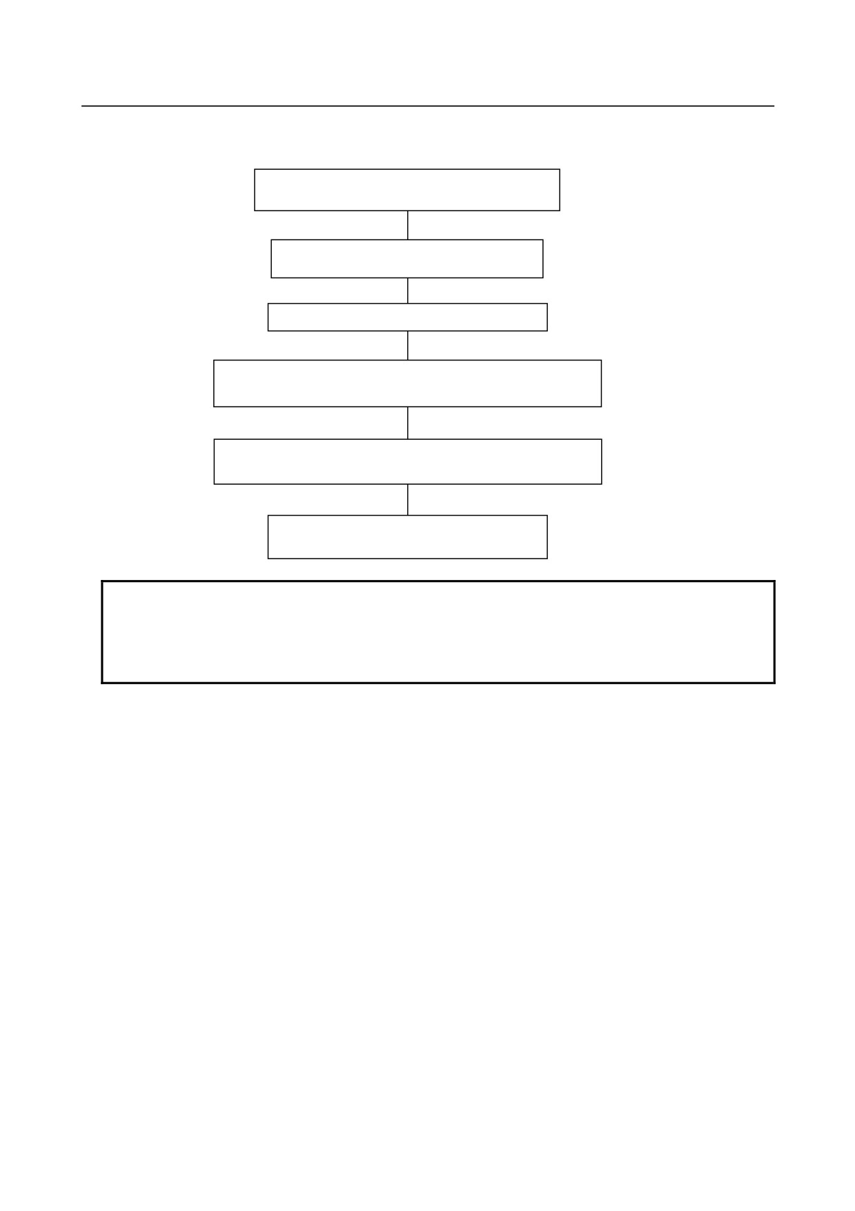
* Reading CH3 and CH4 data
Ensure that the READ request bit (DO22) is set
to "0".
Reset the channel select bit (DO26) to
"0".
(Note)
Set the READ request bit (DO22) to "1".
When CH3 data READY (DI15 of input signal) is set to "1",
input signals DI00 to DI12 represent CH3 data.
When CH4 data READY (DI31 of input signal) is set to "1",
input signals DI16 to DI28 represent CH4 data.
Reset the READ request bit (DO22) to "0".
NOTE
1 After setting the NC READY bit to "1", wait for one second, and then set the READ
request bit to "1".
2 To create the ladder for 4-channel manual measurement, refer to the above
flowchart or timing chart.
- 156 -
B-61813E/06
CONNECTION
9.TEMPERATURE INPUT MODULE
9.7
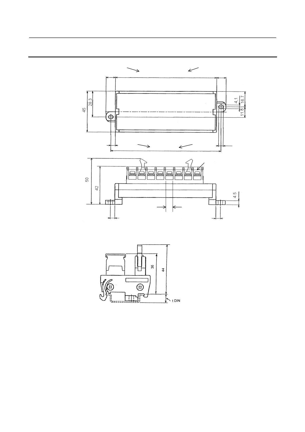
TERMINAL UNIT DIMENSIONS
ATB01B
ATB01A
113
10.5
(153)
10.5
(For thermocouple module)
(For thermoresistance module)
5
5.1
ATB01B
ATB01A
123
(163)
Wire screw: M4
8.2
5
5
Unit: mm
To use a DIN rail, add its height (tDIN) to the dimension shown below.
Unit: mm
- 157 -
10.OPTICAL ADAPTER
CONNECTION
B-61813E/06
10 OPTICAL ADAPTER
The signal cable K1X shown in the general connection diagram (in section 4.1) can be extended to the
maximum length of 200 m with optical fiber cables using an optical adapter for I/O Link i or optical adapter
for I/O Link.
Note that the optical adapter types differ between I/O Link i and I/O Link.
NOTE
1 For the cable K2X, the optical adapter for I/O Link i or optical adapter for I/O Link.
cannot be applied to.
2 In the following cases, make sure to use an optical fiber cable for K1X. For cabling
within the same cabinet, however, this applies only when the cable is 15 m or
longer.
• When the cable is more than 10 meters long.
• When the cable K1X runs between different cabinets and it is impossible to
connect the cabinets with a wire of 5.5 mm2 or thicker.
• When there is concern that the cable K1X is influenced by strong noise.
For example;
When there is a strong electromagnetic noise source beside the cable K1X
such as a welding machine and the like.
When a noise generating cable such as a power cable and the like runs for a
long distance in parallel with the cable K1X.
10.1 SPECIFICATIONS OF THE OPTICAL ADAPTER FOR I/O
Link
The optical adapters for I/O Link include a standard type (A13B-0154-B001) and a high-speed type
(A13B-0154-B004).
If one channel of I/O Link consists of 6 or more optical connection stages, use the high-speed type for it.
Maximum
Maximum number
Relay by optical
Specification
Type
transmission
of connectable
fiber junction
Mass
distance
stages
adapters
200m
5
None
A13B-0154-B001
Standard type
Approx.
100m
5
Up to one point
100g
A13B-0154-B004
High-speed type
100m
16
Impossible
NOTE
1 The optical adapter (A13B-0154-B001 to A13B-0154-B004) for I/O Link is
dedicated to I/O Link. It cannot be used with I/O Link i.
2 It is impossible to use high-speed and standard types together on one I/O Link
line.
3 When the high-speed type optical adapter for I/O Link is used, it is impossible to
use optical fiber junction adapters.
- 158 -
B-61813E/06
CONNECTION
10.OPTICAL ADAPTER
10.2 SPECIFICATIONS OF THE OPTICAL ADAPTER FOR I/O
Link i
Maximum
Maximum number
Relay by optical
Specification
Transfer mode
transmission
of connectable
fiber junction
Mass
distance
stages
adapters
200m
5
None
Standard mode
Approx.
A13B-0154-B101
100m
16
Up to one point
100g
High-speed mode
100m
10
Up to one point
Only one optical adapter type (A13B-0154-B101) is available for I/O Link i. It can be used for both
standard and high-speed transfer modes.
NOTE
1 The optical adapter (A13B-0154-B101) for I/O Link is dedicated to I/O Link i. It
cannot be used with I/O Link.
2 The I/O Unit-A supports no high-speed mode.
Same specification
Optical I/O
Optical I/O
Link adapter
Link adapter
(Master side)
(Slave side)
Recommended optical cable: A66L-6001-0026
10.3 EXTERNAL DIMENSION OF OPTICAL ADAPTER
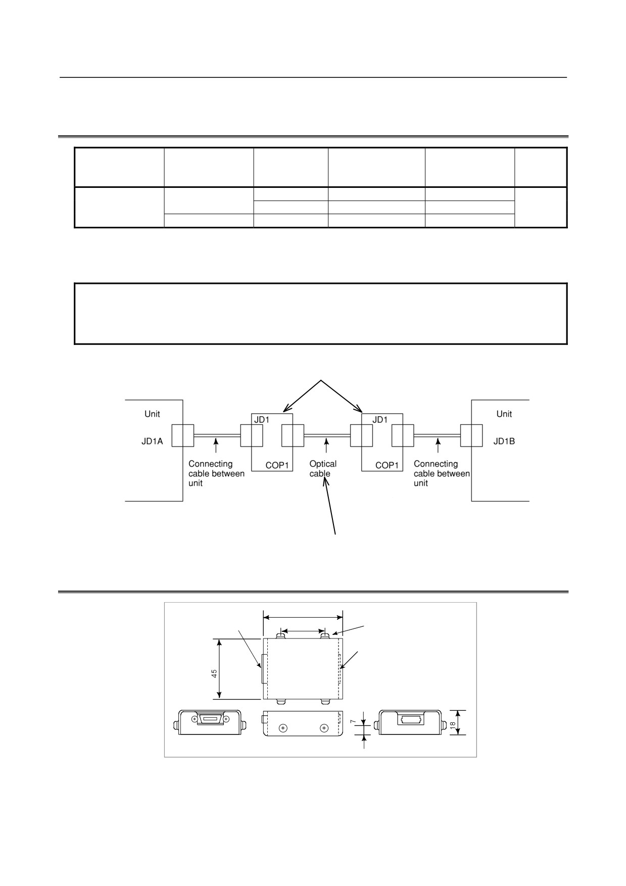
66
Connector for connection to
the unitJD1
4-M3
40
Optical connector
COP23 (for I/O Link i)
FANUC
COP1 (for I/O Link)
Unit: mm
- 159 -
10.OPTICAL ADAPTER
CONNECTION
B-61813E/06
10.4 CONNECTION OF OPTICAL ADAPTER
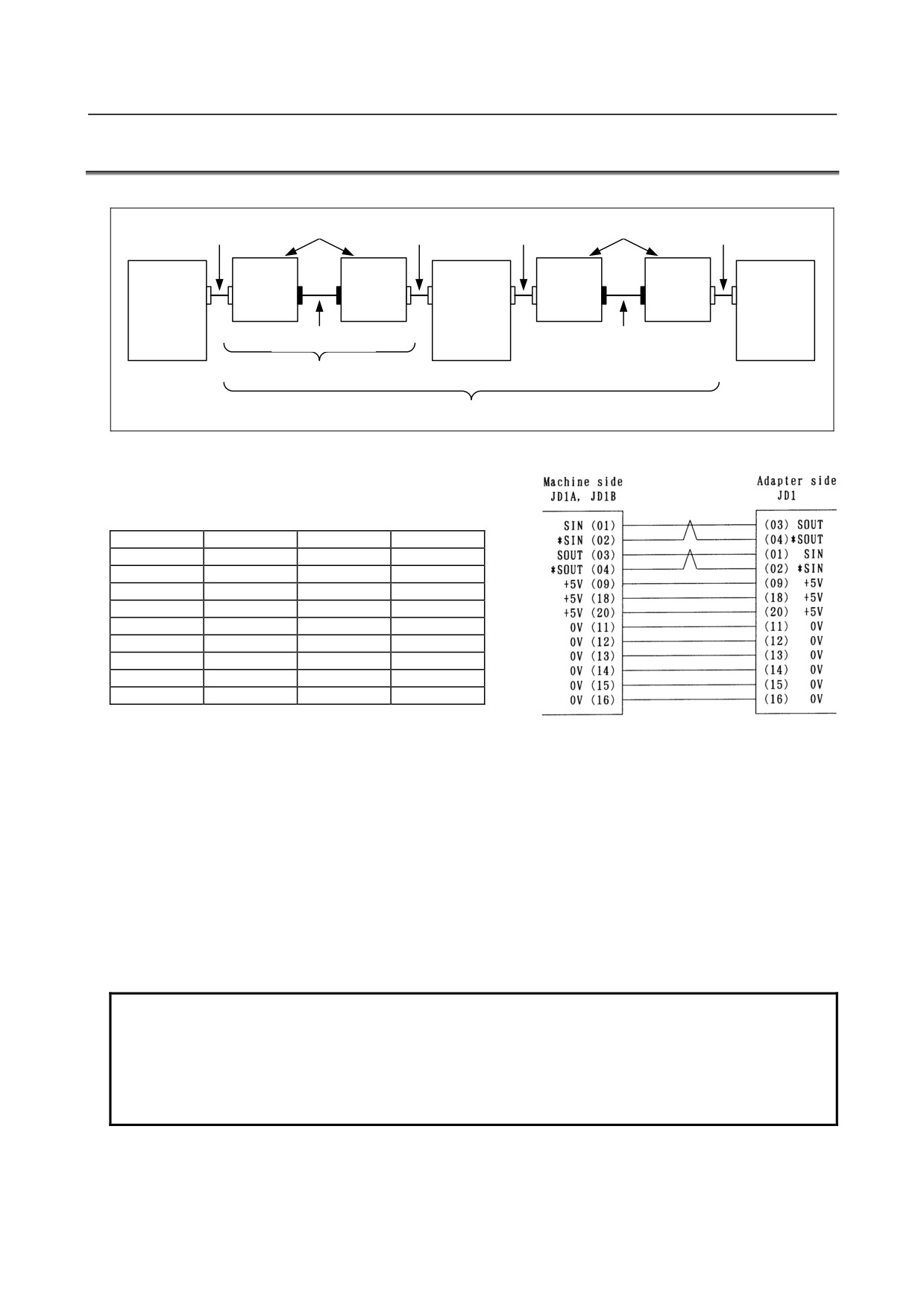
(1) Connection diagram
Same
Same
Connecting cable
Connecting cable
Connecting cable
Connecting cable
specification
specification
between units
between units
between units
between units
Unit
Optical
Optical
Unit
Optical
Optical
Unit
adapter
adapter
adapter
adapter
JD51A/JD1A
JD1 COPx
COPx JD1
JD1B JD1A
JD1 COPx
COPx JD1
JD1B JD1A
Optical fiber cable
Optical fiber cable
One optical fiber cable connection stage
Two optical fiber cable connection stages
(2) Interunit connecting cables K3X
01
SIN
11
0V
02
*SIN
12
0V
03
SOUT
13
0V
04
*SOUT
14
0V
05
15
0V
06
16
0V
07
17
08
18
+5V
09
+5V
19
10
20
+5V
(a) Recommended connector for cable side:
PCR-E20FA (manufactured by HONDA TSUSHIN)
FI30-20S (manufactured by HIROSE ELECTRIC)
FCN-247J020-G/E (manufactured by Fujitsu)
52622-2011 (manufactured by Molex)
(b) Recommended cable (with material): A66L-0001-0284#10P
(c) Cable length: Max.2m (when the recommended cable is used)
(3) Optical cable
<1> Specification (Be sure to use the optical cable conforming to this specification.):
• A66L-6001-0026
<2> Cable length:
See Sections 10.1 and 10.2 for the descriptions of the specifications of each optical adapter.
NOTE
1 The maximum permissible length of the interunit connection cable is 2 m (when a
recommended cable is used). Make the cable as short as possible.
2 The pins enclosed in [ ] are used by the JD44A or JD51A for channel 2 or 3
connection. Do not connect anything to them.
3 Do not connect anything to pins to which no signal is assigned.
- 160 -
B-61813E/06
CONNECTION
10.OPTICAL ADAPTER
10.5 POWER SOURCE OF OPTICAL ADAPTER
Power is supplied to the optical adapter from the CNC or I/O Unit through the cable K3X of I/O Link or I/O
Link i. Use a cable having wires for power supply.
When you use the optical adapter for I/O Link i, please add 50mA per an adapter to required current.
10.6 INSTALLATION CONDITIONS OF OPTICAL ADAPTER
(1) As this adapter is not a closed type, install it in the same closed type cabinet as used for the NC control
unit.
(2) Make sure to ground the case using the case fixing screw of the adapter.
(3) As the adapter is light, it is not necessary to fix it with screws. However, keep it from getting contact
with other circuits lest it should be short-circuited. In addition, when fixing the adapter in a cabinet and
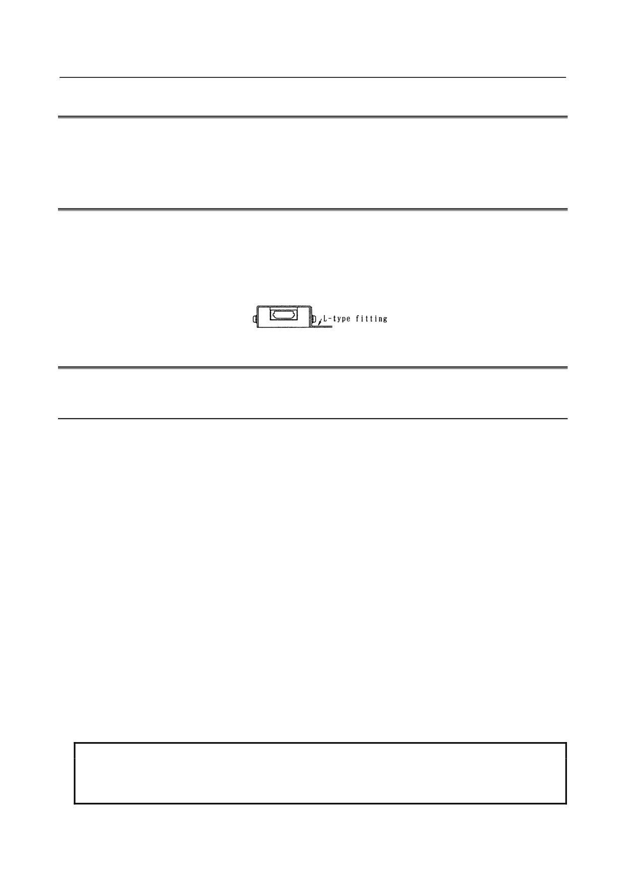
the like, fix it with a L-type fitting using the case fixing screws (M3) of the adapter.
10.7 CAUTIONS FOR USING OPTICAL ADAPTERS
10.7.1 When Using Optical Adapters in Configuring I/O Link i or I/O
Link
The following restrictions are applied when optical adapters are used in configuring I/O Link i or I/O Link.
(CNC)
(I/O-A or the like)
(I/O-A or the like)
(I/O-A or the like)
Master - - - - - Group#0 - - - - - - - - - - - - Group#1 - - - - - - - - • • • • • • -- - - - - - Group#15
↑
↑
↑
↑
Partition #1
Partition #2
Partition #3
Partition #4
Restriction on the number of optical adapters used per I/O Link channel
• When using the standard-type optical adapter for I/O Link:
Up to 5 partitions (I/O Link master -- group #0 -- group #1 -- ... -- group #15) can be configured with
optical adapter.
Use electrical cables for the K1X in the other partitions.
• When using the high-speed type optical adapter for I/O Link:
The high-speed type performs optical-electrical conversion faster than the standard-type.
All (16) partitions (master -- group #0 -- group #1 -- ... -- group #15) can be configured with optical
adapter.
Restriction on the number of optical adapters used per I/O Link i channel
• When using optical adapters for I/O Link i in the normal communication mode:
Up to 16 (for the high-speed mode, up to 10) I/O Link i partitions can be configured using optical
adapters.
Use electrical cables for the K1X in the other partitions.
NOTE
1 If an optical fiber cable is used with /O Link i or I/O Link, the optical adapters
connected to each end of the optical fiber cable must be those designed to the
same specifications.
- 161 -
10.OPTICAL ADAPTER
CONNECTION
B-61813E/06
NOTE
2 When 6 or more I/O Link partitions are configured using optical adapters, I/O Link
cannot operate normally if a standard-type optical adapter is used even in one
partition.
When using optical adapters in 6 or more partitions, do not use the standard-type
optical adapter; use only the high-speed type optical adapter.
Parts required in configuring one partition using an optical adapter
(1) When configuring 5 or fewer partitions with optical adapter for I/O Link
Two standard-type optical adapters for I/O Link
Two unit-to-unit connecting cables (K3X)
One optical fiber cable
(2) When configuring six or more partitions with optical fibers
Two high-speed type optical adapters for I/O Link
Two unit-to-unit connecting cables (K3X)
One optical fiber cable
(3) When configuring 16 or fewer partitions with optical adapter for I/O Link i
Two optical adapters for I/O Link i
Two unit-to-unit connecting cables (K3X)
One optical fiber cable
3 The I/O Unit-A does not support the high-speed mode of I/O Link i.
10.7.2 When Using Two I/O Link i or I/O Link Channels
Using two I/O Link i or I/O Link channels requires using the I/O Link connector adapter.
When optical adapters are used, optical fiber cables can be used in all partitions (all partitions of channels 1
and 2) ahead of the I/O Link connector adapter. No optical fiber cable can be used between the CNC
(JD44A or JD51A) and I/O Link connector adapter
(JD44B). Use a
1-meter electrical cable
(A02B-0236-K848).
NOTE
Do not have the cable length from the CNC (JD44A or JD51A) to the I/O Link
connector adapter and then to the optical adapter exceed 2 meters in total.
(Example) Using optical adapters in partition 1 of channel 2
Electrical cable K1X
Group#0
CNC
I/O Link connector adapter
See (1) of Section 4.5.
I/O Unit, etc
Channel 1
JD44A
JD1B
JD44B
JD51A
JD1A-1
Optical adapter
Group#0
JD1A-2
I/O Unit, etc
A02B-0236-K848
JD1B
(1m)
Channel 2
Optical fiber cable
Keep the total cable length within 2 meters.
Electrical cable
See descriptions about unit-to-unit connecting cables K3X in Section 10.4.
- 162 -
B-61813E/06
CONNECTION
10.OPTICAL ADAPTER
10.7.3 When Using Three I/O Link i or I/O Link Channels
Using three I/O Link i or I/O Link channels requires using the 3-channel I/O Link connector adapter.
When optical adapters are used, optical fiber cables can be used in all partitions (all partitions of channels 1,
2, and 3) ahead of the I/O Link connector adapter. No optical fiber cable can be used between the CNC
(JD51A) and I/O Link connector adapter (JD51B). Use a 1-meter electrical cable (A02B-0303-K849).
NOTE
Do not have the cable length from the CNC (JD51A) to the I/O Link connector
adapter and then to the optical adapter exceed 2 meters in total.
(Example)
Using optical adapters in partition 1 of each of channels 1 and 2
Keep the total cable length within 2 meters.
Electrical cable
See descriptions about unit-to-unit
connecting cables K3X in Section 10.4.
CNC
Optical fiber cable
Group#0
(30i/31i/32i)
I/O Unit, etc
Channel 1
JD1B
JD51A
JD51B
JD44A-1
Optical adapter
Group#0
JD44A-2
I/O Unit, etc
A02B-0303-K849
Channel 2
(1m)
JD1B
JD1A
Optical fiber cable
3-channel I/O Link
connector adapter
Electrical cable
Group#0
See descriptions about unit-to-unit
I/O Unit, etc
connecting cables K3X in Section
10.4.
JD1B
Electrical cable K1X
See (1) of Section 4.5.
Channel 3
10.8 OPTICAL FIBER CABLE
An optical fiber cable is used to connect between the optical connector of an optical adapter and that of
another optical adapter. Unlike the conventional power cables, optical fiber cables need special care in
installation and handling. No optical fiber cable can be used on movable parts.
- 163 -
10.OPTICAL ADAPTER
CONNECTION
B-61813E/06
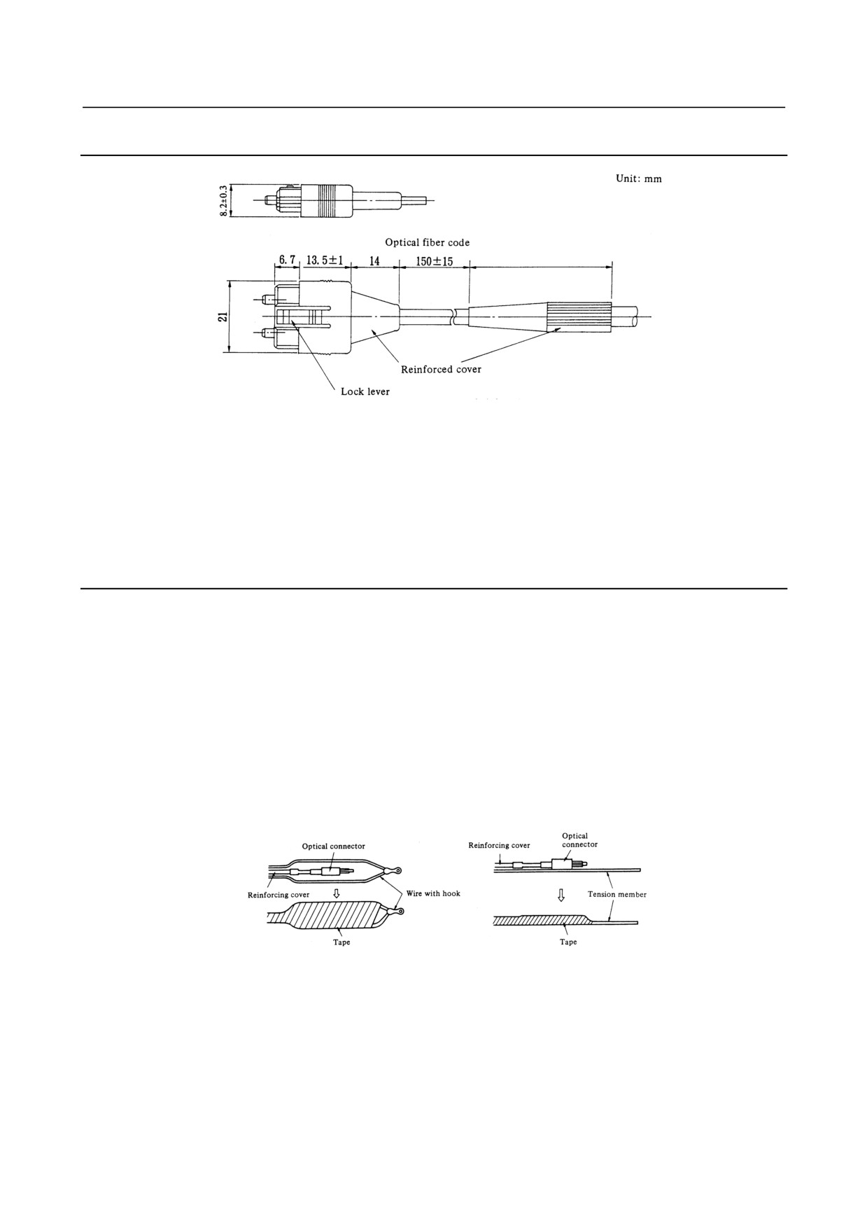
10.8.1 External View of Optical Fiber Cable
Reinforced optical fiber code diameter: 8.4mm
Tensile strength: Optical fiber code: 25kg
Optical fiber code-connector: 2kg
Reinforcing cover: 150kg
Bending radious of optical fiber code with reinforcing cover: 50mm
(1) Standard length of an optical fiber cable is 10, 15, 20, 30, 50, 100, and 200 meters.
(2) No machine tool builder is allowed to cut or joint optical fiber cables.
(3) If it needs to relay on cabling, use optical fiber junction adapter. Up to the relay points are allowed on
a transmission line.
10.8.2 Notice of Optical Fiber Cable Handling
(1) Even though reinforcing cover used on the optical fiber code has enough mechanical strength, be sure
not to be damaged by heavy materials drop.
(2) Detaching and attaching of optical connector should always be made by touching connector. Optical
fiber code should not be touched when replacement.
(3) Optical connector is automatically locked with upper side lock levels after being connected. It is
impossible to pull out the connector without releasing the lock levers.
(4) Optical connector cannot be connected oppositely. Be sure the connector direction when connection is
done.
(5) Optical connector should be processed as follows before laying of optical fiber cable.
Fix a reinforcing cover to a wire with hook or tension member by a tape.
At laying hook the wire or pull the tension member taking enough care that optical connector does not
receive pulling strength.
(6) Reinforcing cover is fixed to cable lamp so that optical fiber cable could not weigh directly the
connecting part of connector.
(7) Notice that optical connector's chip is clear.
The attached protect cap must be always put on when optical connector is not used.
Remove dirty with a clear tissue or absorbent cotton (cotton with ethyl alcohol is applicable). No other
organic solvent than ethyl alcohol cannot be used.
- 164 -
B-61813E/06
CONNECTION
10.OPTICAL ADAPTER
10.8.3 Optical Fiber Cable Clamping Method
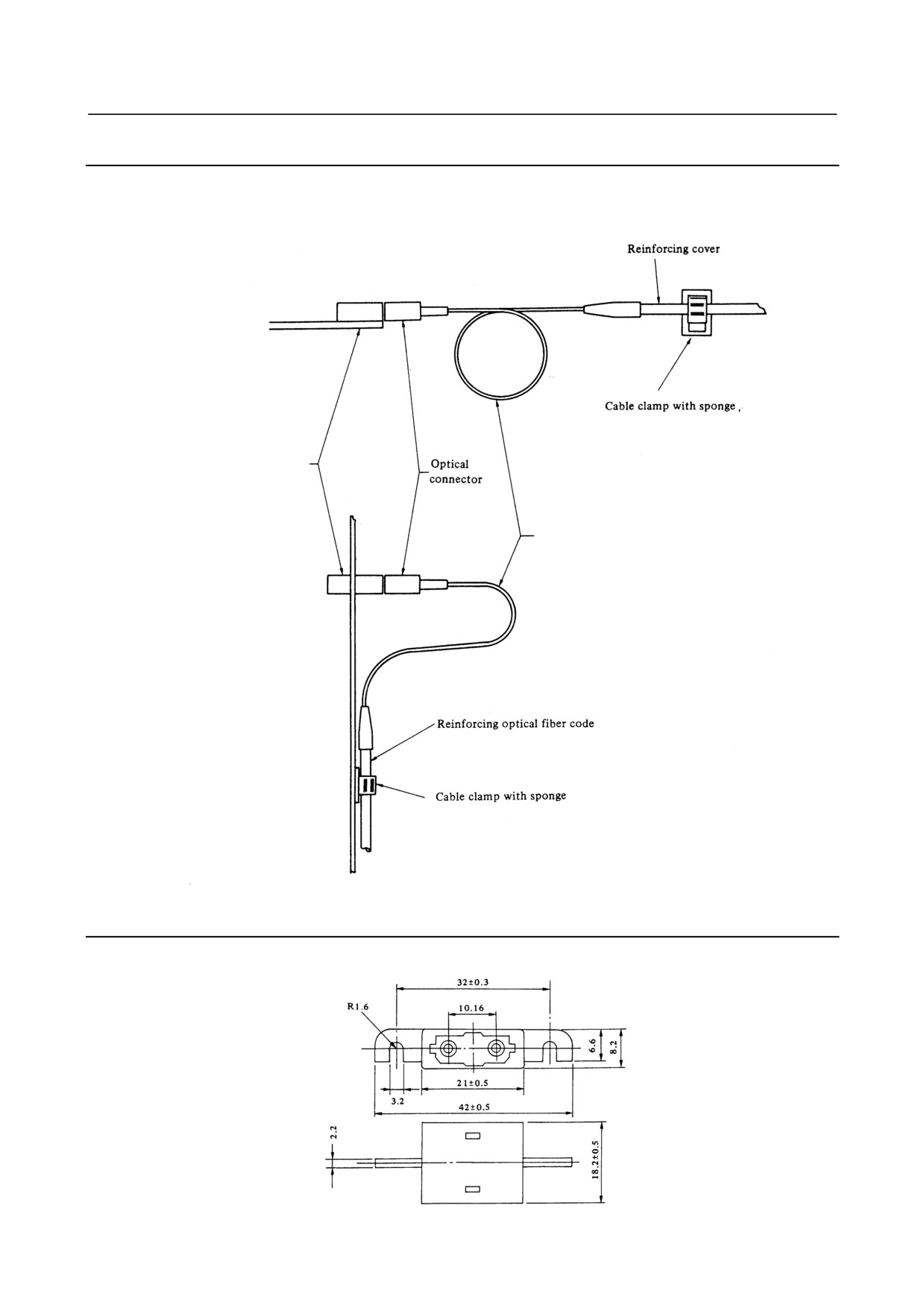
When reinforcing cover is fixed at cable clamp with sponge, enough sag at optical fiber code as shown
below is necessary so that connecting part of optical should not be weighed directly by optical fiber cable.
Optical fiber junction
adapter or optical data
link module
Optical fiber cable
(Bending radius should be more
than 25mm, and the reinforcing
sheath portion is 50 mm or longer.)
10.8.4 Relay Using an Optical Fiber Junction Adapter
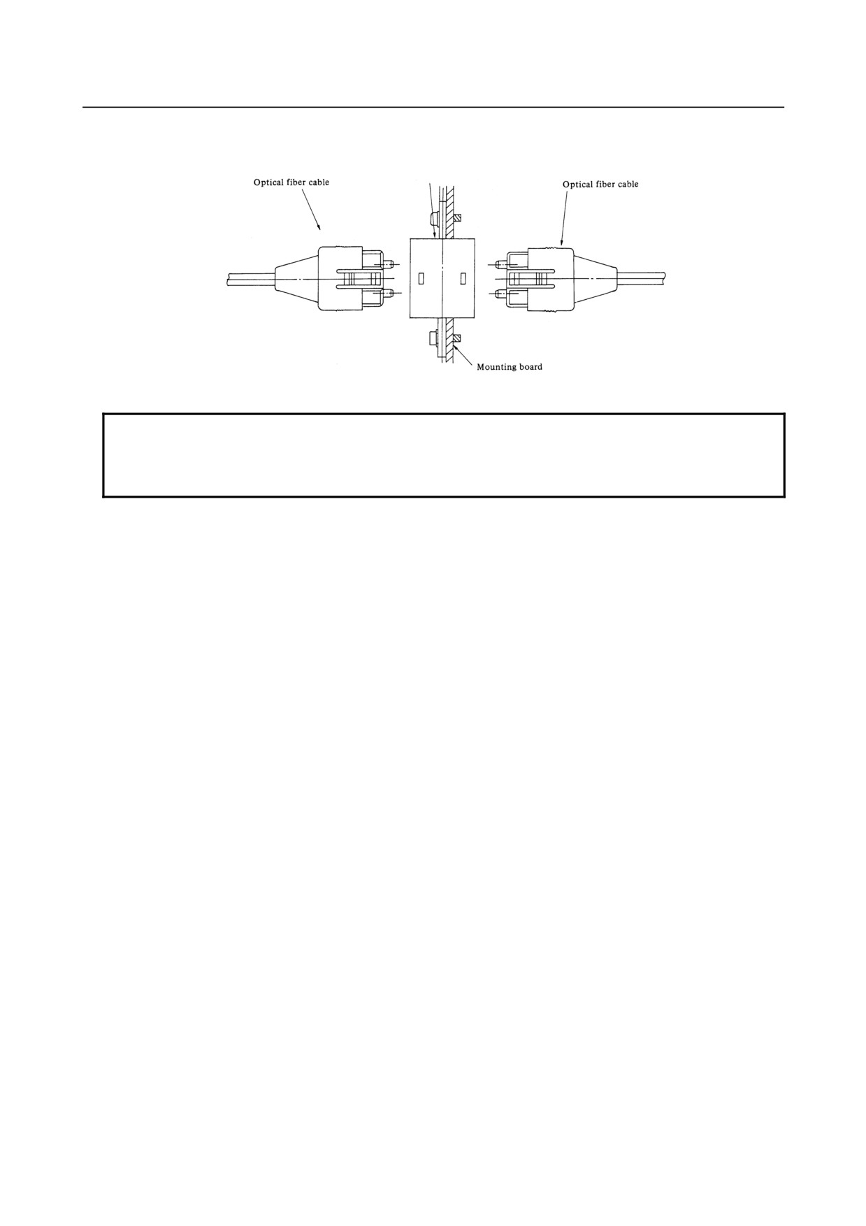
(1) External view of an optical fiber junction adapter
- 165 -
10.OPTICAL ADAPTER
CONNECTION
B-61813E/06
(2) Example of the use of an optical fiber junction adapter
Optical fiber junction adapter
Specification: A02B-0094-K841
NOTE
1 Up to one relay points are permitted.
2 No optical fiber junction adapter can be used with the high-speed optical adapter
for I/O Link.
(3) Installing the optical fiber junction adapter
The optical fiber junction adapter should be installed within a cabinet, as a rule. If it is impossible to avoid
installing it within a cabinet, protect the adapter and the optical fiber cable portions (such as connectors and
cords) not covered with reinforcement coating from the outside air by, for example, covering them with
packing.
(4) Environmental resistance of the optical fiber junction adapter
• The optical fiber junction adapter is not waterproof. Even when optical fiber cables are attached to
both ends of the adapter, there are very small gaps in the linked portions, so water resistance cannot be
expected.
• When optical fiber cables are attached to both ends of the junction adapter installed in a normal
environment (such as within a cabinet), it is unlikely that dust will penetrate between the adapter and
optical fiber cable to the degree that it may hamper normal optical linkage. If one or both ends of the
adapter are left open, dust and dirt may accumulate even when the adapter is in a normal environment
(such as within a cabinet). The dust and dirt on the adapter ends is likely to hamper normal optical
linkage when the optical fiber cables are attached. In such a case, clean the junction adapter and the
optical connector using the optical fiber junction adapter cleaning method described below.
• Do not allow cutting fluid to splash over the adapter or those optical cable portions (such as connectors
and cords) that are not covered with reinforcement coating. If the inside of the adapter and fiber end
surfaces are contaminated with cutting fluid, a malfunction may occur.
(5) Cleaning
If the optical fiber junction adapter, optical adapter, and optical fiber cable are soiled, clean them according
to the following procedures.
• Cleaning the optical fiber junction adapter and optical adapter
First, clean the entire housing by wiping it with a cloth moistened with, or by washing it in ethyl
alcohol. Similarly, wash the two sleeves in the adapter or wipe them with a cotton swab or the like.
• Cleaning optical fiber cables
For the optical fiber cables, it is important to clean the connectors at their ends. Any soiling on the
optical fiber cable end surfaces will hamper optical transmission, resulting in a malfunction. Wipe the
optical fiber cable end surfaces (that is, the ferrule end surfaces) thoroughly with a soft, clean cloth
(like gauze) moistened with ethyl alcohol, in the same way as described above.
- 166 -
B-61813E/06
CONNECTION
10.OPTICAL ADAPTER
The use of cotton swabs may prove convenient. The fiber end surfaces of low-loss optical fiber cables
are lower than the ferrules. To remove any soiling from the fiber end surfaces completely, push the
cotton swab or gauze into the depressions all the way through while rotating the ferrule. If the ferrules
and optical connectors are contaminated with oily substances, and they may extend over a cleaned
fiber end surface when it is attached to the optical-to-electrical conversion module, it is a good idea to
wash them before wiping the optical fiber cable end surfaces, using the procedure stated above.
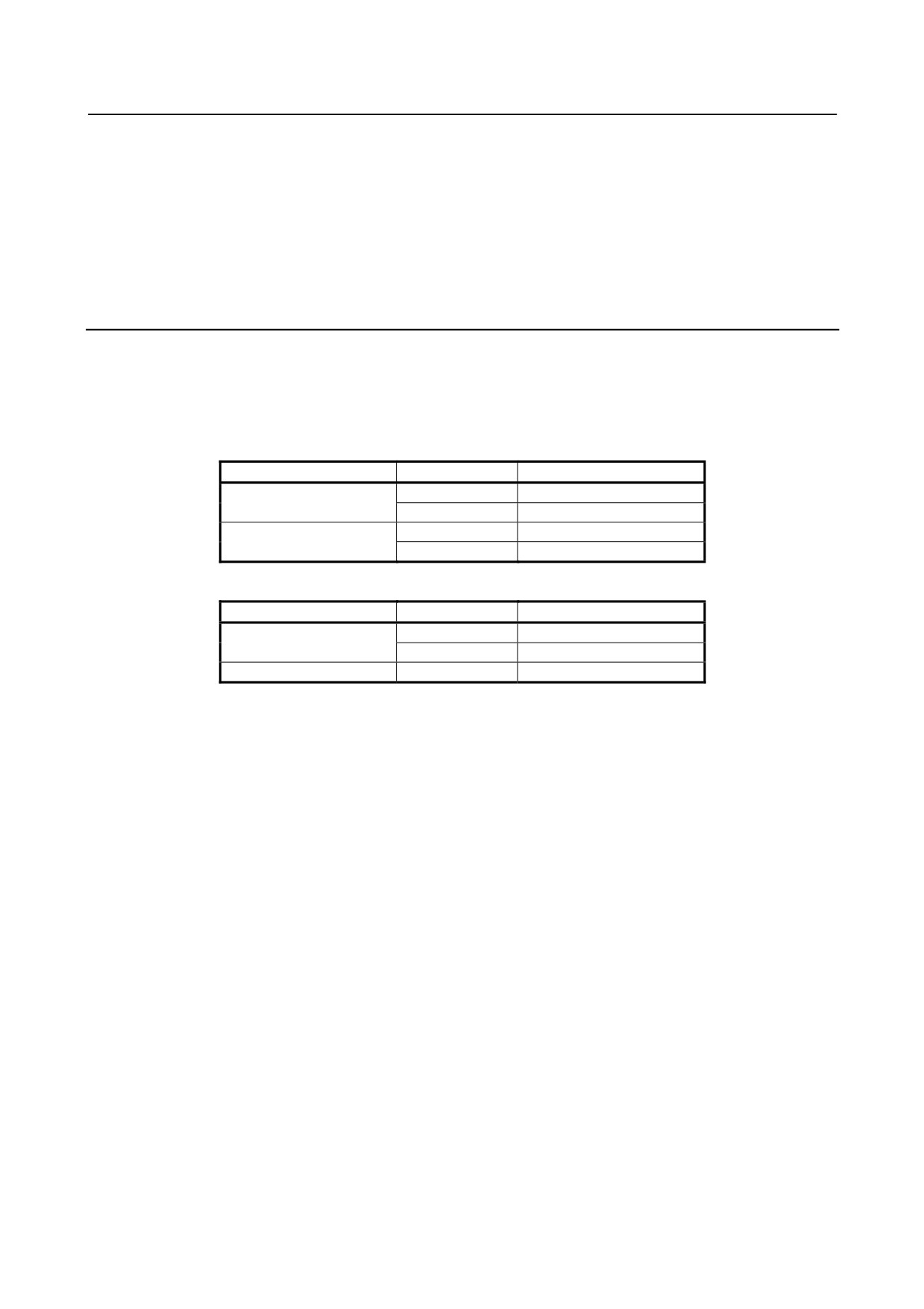
10.8.5 Maximum Transmission Distance by Optical Fiber Junction
Cable
Maximum transmission distance by optical fiber junction cable is shown below:
The maximum transmission distance varies depending on the number of relay points supported by optical
fiber junction adapters. When the high-speed type optical adapter for I/O Link is in use, no optical fiber
junction adapter can be used.
I/O Link
Optical adapter
Relay points
Max. trans. distance
0
200m
Standard type
1
100m (total)
0
100m
High-speed type
1
Not applicable
I/O Link i
Communication method
Relay points
Max. trans. distance
0
200m
Normal mode
1
100m
High-speed mode
1
100m
- 167 -
11.I/O Link DUMMY UNIT
CONNECTION
B-61813E/06
11 I/O Link DUMMY UNIT
11.1 OVERVIEW
If a slave unit (such as the FS0, Power Mate, I/O Unit-MODEL A, or connection unit) is removed from the
FANUC I/O Link (Note), the group number for those that followed the removed slave unit changes. So, it
becomes necessary to change the PMC assignment. However, connecting a FANUC I/O Link dummy unit
in place of the removed slave unit makes it unnecessary to change PMC assignment.
This chapter describes the electrical and structural specifications that apply to the FANUC I/O Link dummy
unit when it is connected to the FANUC I/O Link.
NOTE
1 The I/O Link dummy unit is dedicated to I/O Link. It cannot be used with I/O Link i.
2 Some i series CNC models can manage the group numbers of I/O Link slaves by
parameter setting. For details, refer to the PMC Programming Manual "Selectable
I/O Link Assignment Function".
11.2 SPECIFICATION: A13B-0167-B001
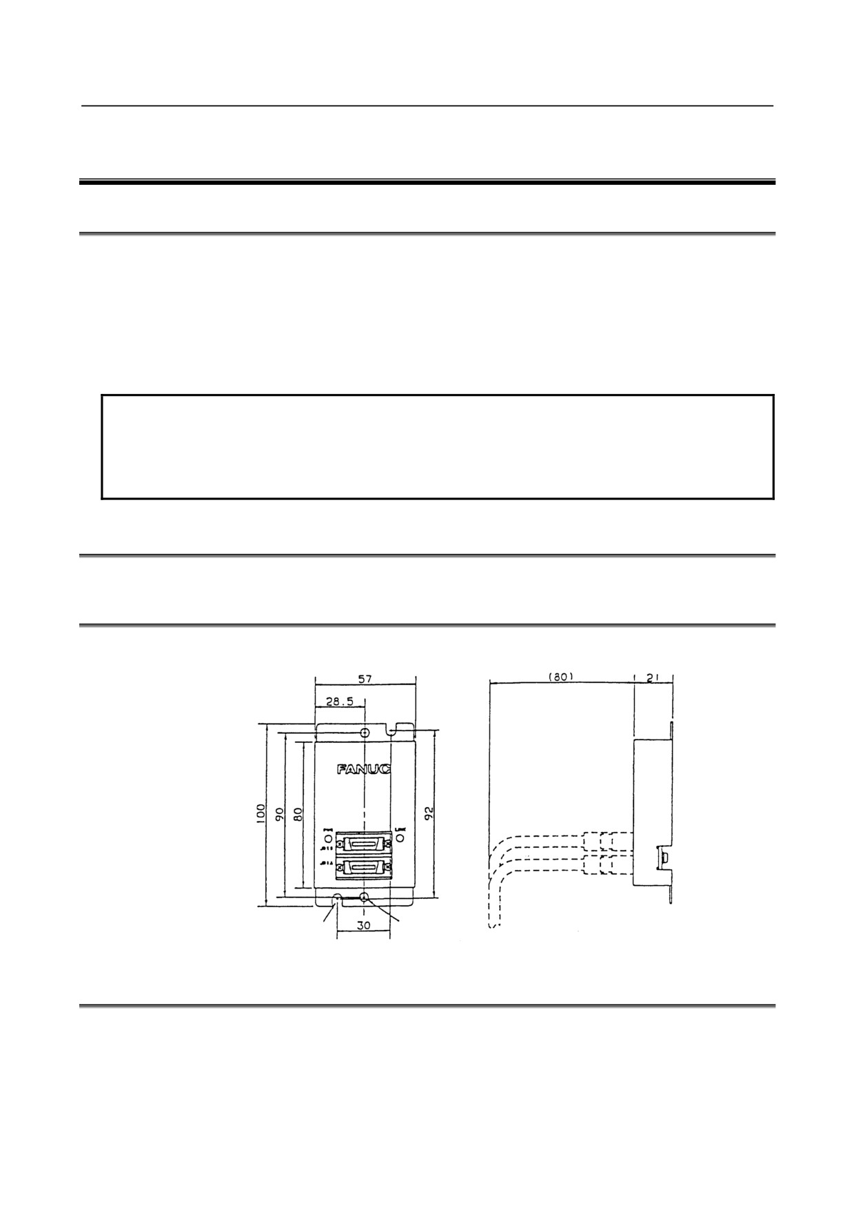
11.3 EXTERNAL DIMENSIONS
Units: mm
Mounting hole for 2-M5
Mounting hole for 2-M4
11.4 LED INDICATORS
(1) PWR:
Lights when the FANUC I/O Link dummy unit is supplied with power.
(2) LINK:
Lights when the FANUC I/O Link is performing communication.
- 168 -
B-61813E/06
CONNECTION
11.I/O Link DUMMY UNIT
11.5 WEIGHT
(1) Main unit: Approximately 120 g
11.6 POWER REQUIREMENTS
Power is supplied to the I/O Link dummy unit from the CNC or I/O Unit through the cable K3X of I/O Link.
Use a cable having wires for power supply.
Required current: 180 mA (maximum)
11.7 INSTALLATION CONDITIONS
This unit is not hermetically sealed. So, it must be installed in a cabinet that is hermetically sealed to the
same level as a cabinet for the NC. The cabinet must be installed in a location where the following
environmental requirements are satisfied.
(1) Ambient temperature
Operating: 0 to 55°C
Storage and transportation: -20 to 60°C
(2) Humidity
Normal:
75% or less (relative)
Short-period (within one month): 95% (maximum)
(3) Vibration
Operating: 0.5 G or less
11.8 CONNECTION DIAGRAMS
11.8.1 When not Connecting FANUC I/O Link Dummy Units in Series
CNC
CNC
Cell controller
Cell controller
JD1A
JD1A
FANUC I/O Link
dummy unit
Operator's panel
Operator's panel
connection unit
connection unit
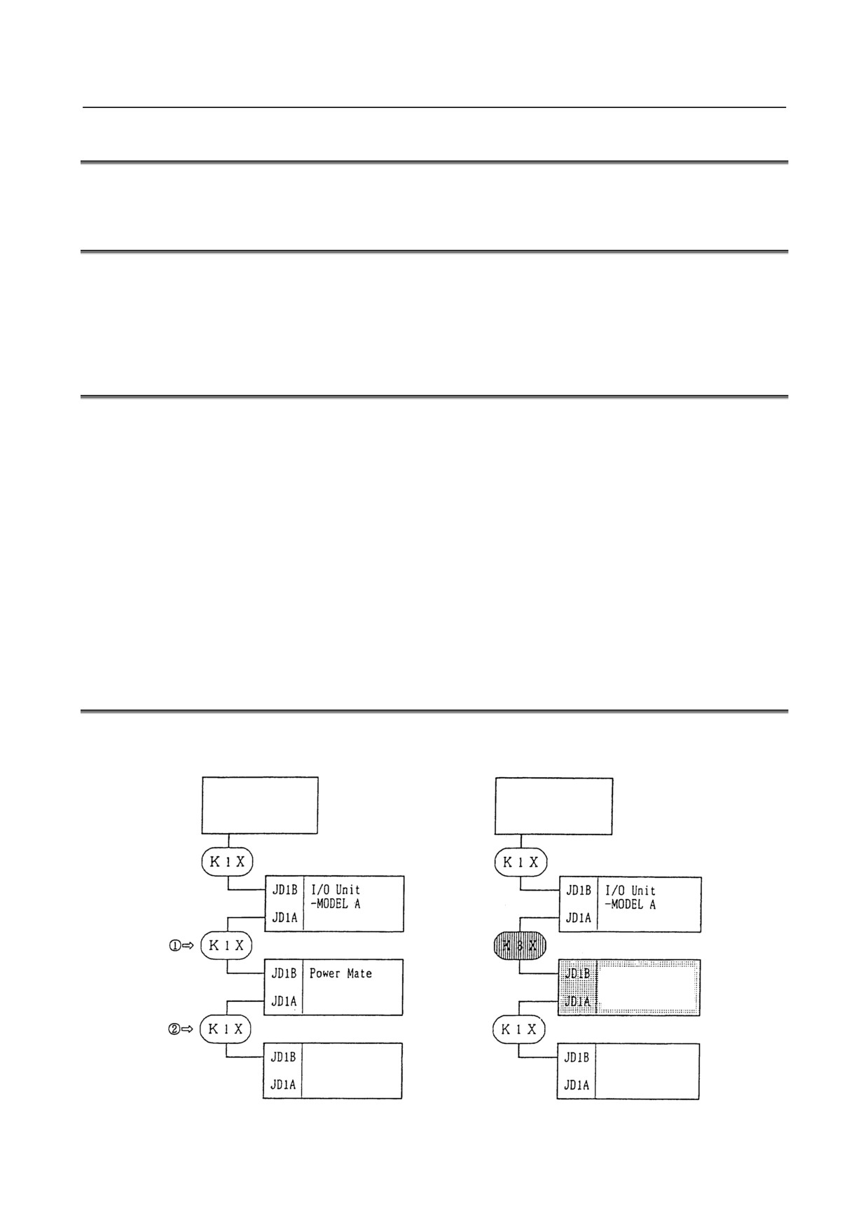
Fig. 11.8.1 Example of Using the FANUC I/O Link Dummy Unit (in Place of the Power Mate)
- 169 -
11.I/O Link DUMMY UNIT
CONNECTION
B-61813E/06
(1) Replacing a cable
The FANUC I/O Link dummy unit is supplied with power from the preceding or following group via
a K3X cable. So, the K1X cable at either JD1A or JD1B of the dummy unit must be replaced with the
K3X cable (c or d in Fig. 11.8.1).
CAUTION
Do not attach a K3X cable to JD1A and JD1B simultaneously.
(2) Cable length
K1X cable:
10 m (maximum) (for cabling within the same cabinet, up to 15 m)
K3X cable:
2 m (maximum)
11.8.2 Connecting FANUC I/O Link Dummy Units in Series
FANUC
FANUC
FANUC
FANUC
Unit with
Unit with
I/O Link
I/O Link
I/O Link
I/O Link
FANUC I/O
FANUC I/O
dummy
dummy
dummy
dummy
Link
Link
unit
unit
unit
unit
Up to two units
Up to ten
Up to two units
Up to two meters
meters
Up to two meters
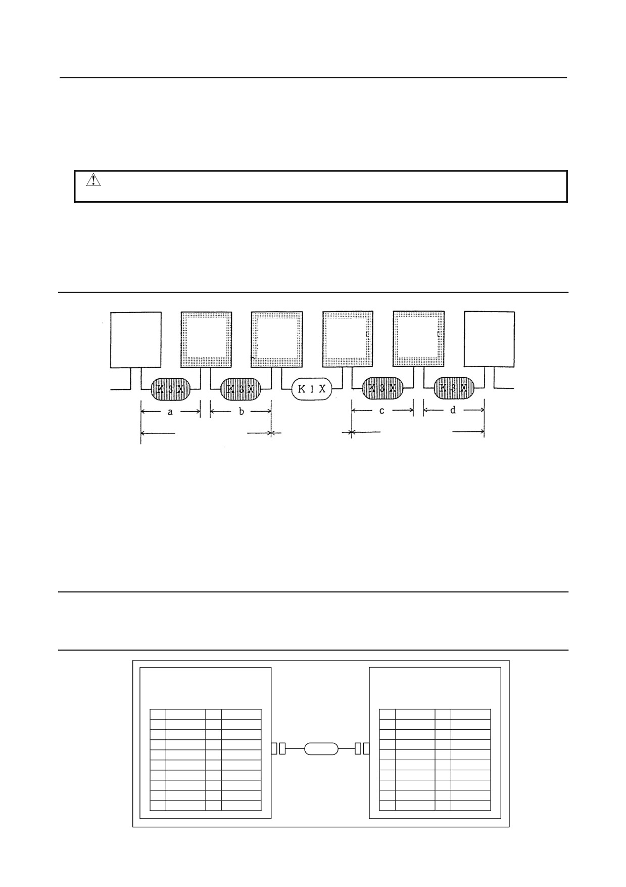
Fig. 11.8.2
(1) Number of FANUC I/O Link dummy units that can be used in succession
Up to two FANUC I/O Link dummy units can be connected via a K3X cable to a unit that supplies
power to them. (See Fig. 11.8.2.)
(2) Cable length
K1X cable:
10 m (maximum) (for cabling within the same cabinet, up to 15 m)
K3X cable:
2 m (maximum) in total (a + b ≤ 2 m and c + d ≤ 2 m)
11.8.3 Grounding
Ground the case of the FANUC I/O Link dummy unit.
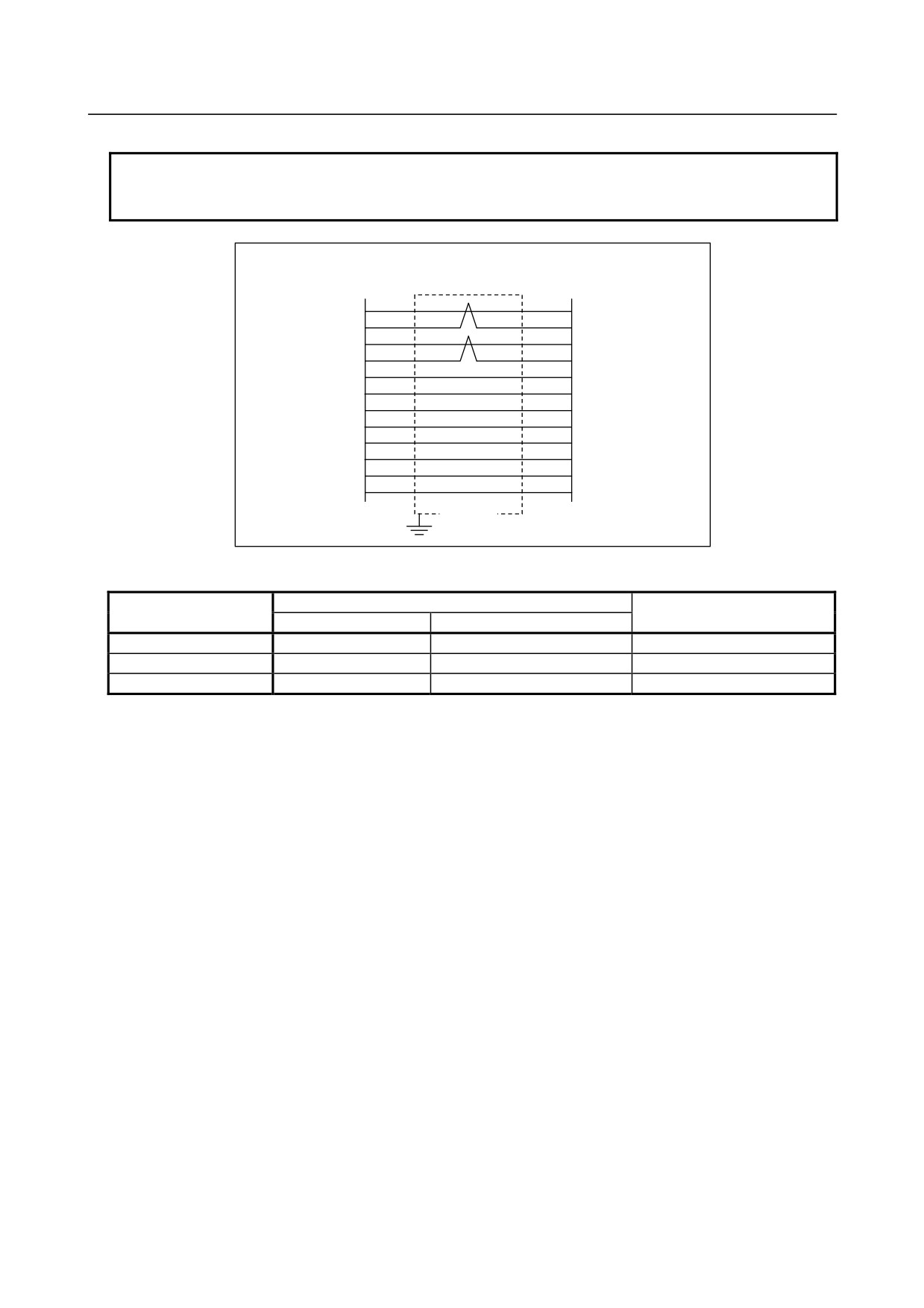
11.8.4 K3X Cable
CNC unit, AIF01A, etc.,
FANUC I/O Link dummy unit
or
or
FANUC I/O Link dummy unit
AIF01A, etc.,
JD51A,JD44A,JD1A
JD51B,JD44B,JD1B
1
SIN1
11
0V
1
SIN1
11
0V
Connector (see the
2
*SIN1
12
0V
diagram below.)
2
*SIN1
12
0V
3
SOUT1
13
0V
3
SOUT1
13
0V
4
*SOUT1
14
0V
4
*SOUT1
14
0V
K3X
5
[ ]
15
0V
5
[ ]
15
0V
6
[ ]
16
[ ]
6
[ ]
16
[ ]
7
[ ]
17
[ ]
7
[ ]
17
[ ]
8
[ ]
18
+5V
8
[ ]
18
+5V
9
+5V
19
[ ]
9
+5V
19
[ ]
10
[ ]
20
+5V
10
[ ]
20
+5V
- 170 -
B-61813E/06
CONNECTION
11.I/O Link DUMMY UNIT
NOTE
The pins enclosed in [ ] are used by the JD44A, JD44B, JD51A, or JD51B for
channel 2 or 3 connection. Do not connect anything to them.
JD1A
JD1B
1
3
SIN1
SOUT1
2
4
*SIN1
*SOUT1
3
1
SOUT1
SIN1
4
2
*SOUT1
*SIN1
0V
11
11
0V
12
12
0V
0V
13
13
0V
0V
0V
14
14
0V
15
15
0V
0V
9
9
+5V
+5V
18
18
+5V
+5V
20
20
+5V
+5V
Shield
• Cable connector
Pin
Manufacturer
Housing
Soldering type
Crimping type
Honda Tsushin
PCR-E20FS
PCR-E20FA
PCR-V20LA
Hirose Electric
FI-40-20S
FI-30-20S
FI-20-CV2
Fujitsu
-
FCN-247J020-G/E
FCN-240C020-Y/S
• Use twisted-pair wires for the SIN, *SIN, SOUT, and *SOUT signals.
• Recommended wires : A66L-0001-0284#10P (twisted-pair wires with common shielding)
• Maximum cable length : 2 m (when recommended wires are used)
• Do not connect a wire to an idle pin.
• Connect the cable shielding to the grounding plate of the cabinet via a metal cable clamp at JD1A. (See
the applicable CNC unit connection manual.)
- 171 -
12. TWO-CHANNEL I/O Link
CONNECTOR ADAPTER
CONNECTION
B-61813E/06
12 TWO-CHANNEL I/O Link CONNECTOR
ADAPTER
12.1 OVERVIEW
With some i series CNC models, it is possible to use up to two I/O Link i interface channels and up to three
I/O Link interface channels. These channels make it possible to increase the number of I/O points to
4096/4096.
This chapter explains how to connect a 2-channel I/O Link connector adapter required in using the
2-channel function for I/O Link i or I/O Link.
NOTE
For the CNCs that can use this function, refer to the connection manual
(hardware) of each CNC.
For information on how to use this function, the PMC models that can use this
function, the series and edition of the PMC management software, and the series
and edition of the CNC management software, refer to the FANUC PMC LADDER
LANGUAGE PROGRAMMING MANUAL.
12.2 SPECIFICATION: A20B-1007-0680
Weight: 60g
12.3 CONNECTION FOR USE OF TWO I/O Link i or I/O Link
CHANNELS
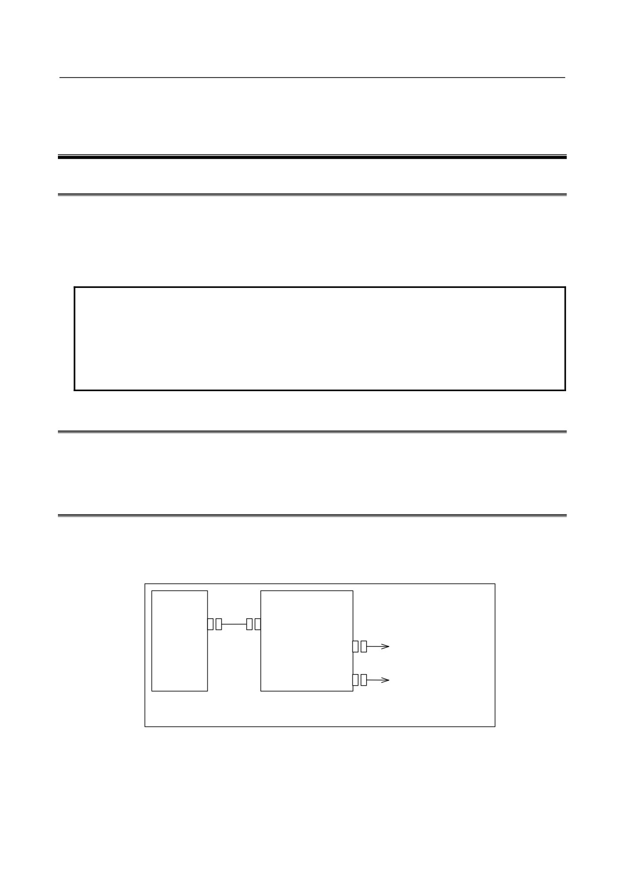
When using the second channel, make a branch from I/O Link i or I/O Link with the 2-channel I/O Link
connector adapter.
Connection
CNC unit
2-channel I/O Link
connector adapter
JD44A/
JD44B
JD51A
JD1A-1
Channel 1
I/O Link i or I/O Link
Channel 2
JD1A-2
I/O Link i or I/O Link
Connections ahead of the 2-channel I/O Link connector adapter
are the same as for the conventional I/O Link i or I/O Link.
- 172 -
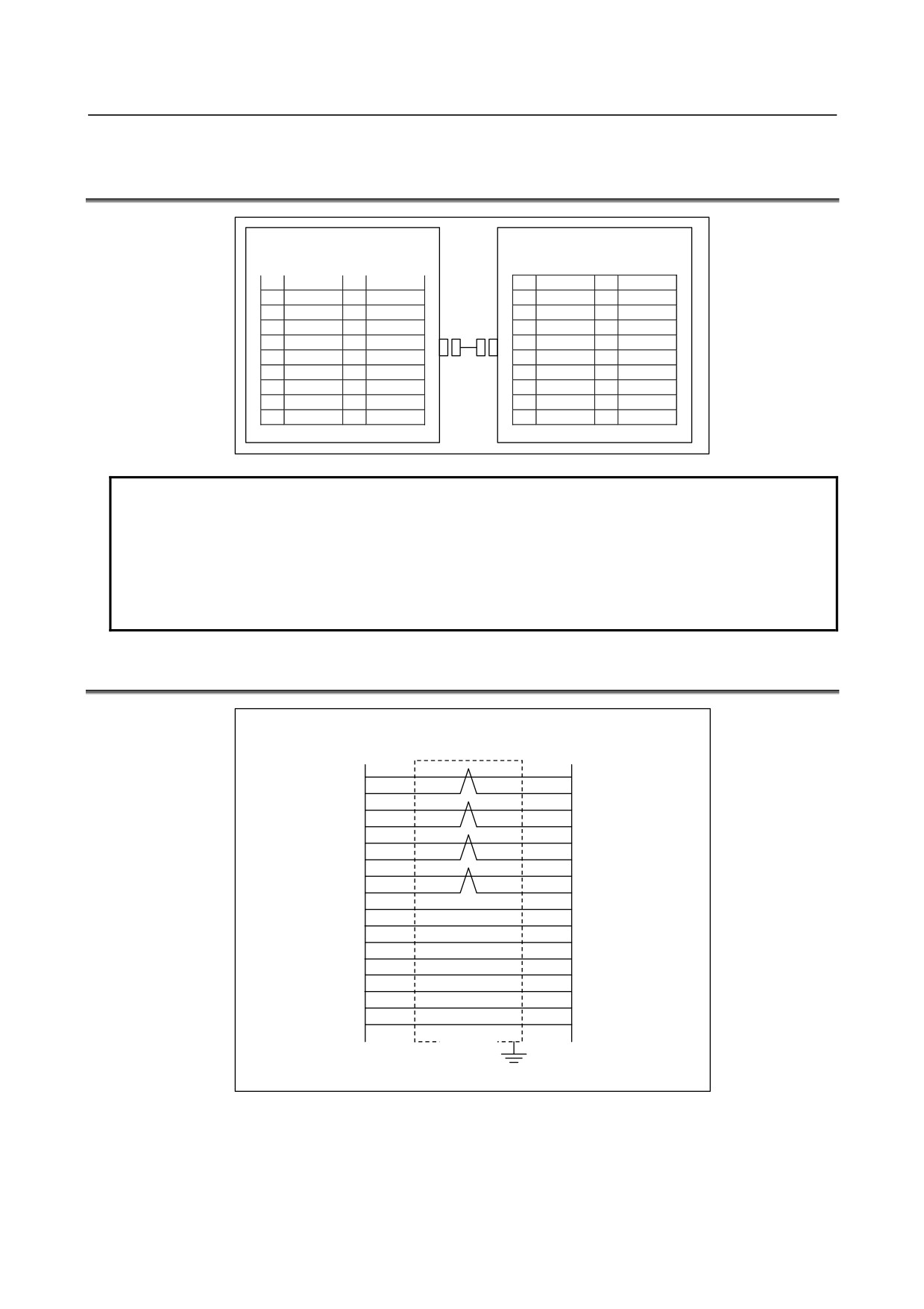
12. TWO-CHANNEL I/O Link
B-61813E/06
CONNECTION
CONNECTOR ADAPTER
12.4 CONNECTING THE CNC WITH TWO-CHANNEL I/O Link
CONNECTOR ADAPTER
CNC unit
2-channel I/O Link connector
JD44A or JD51A
adapter JD44B
(such as PCR-E20MDK-SL-A)
(PCR-E20MDT)
1
SIN1
11
0V
1
SIN1
11
0V
2
*SIN1
12
0V
2
*SIN1
12
0V
3
SOUT1
13
0V
3
SOUT1
13
0V
4
*SOUT1
14
0V
4
*SOUT1
14
0V
5
SIN2
15
0V
5
SIN2
15
0V
6
*SIN2
16
[ ]
6
*SIN2
16
0V
7
SOUT2
17
[ ]
7
SOUT2
17
8
*SOUT2
18
(+5V)
8
*SOUT2
18
(+5V)
9
(+5V)
19
[ ]
9
(+5V)
19
10
[ ]
20
(+5V)
10
20
(+5V)
NOTE
1 The +5V pin enclosed in () is intended to supply power to an optical adapter for
connection through an optical fiber cable. When using no optical adapter, do not
connect the +5V pin.
2 The pins enclosed in [ ] are used by the JD51A for channel 3 connection. Do not
connect anything to them.
3 Do not connect anything to pins to which no signal is assigned.
12.5 CABLING
CNC unit
I/O Link connector
JD44A,JD51A
adapter JD44B
1
3
SIN1
SOUT1
2
4
*SIN1
*SOUT1
SOUT1
3
1
SIN1
4
2
*SOUT1
*SIN1
5
7
SIN2
SOUT2
*SIN2
6
8
*SOUT2
7
5
SOUT2
SIN2
8
6
*SOUT2
*SIN2
11
11
0V
0V
12
12
0V
0V
0V
13
13
0V
14
14
0V
0V
15
15
0V
0V
9
9
(+5V)
(+5V)
18
18
(+5V)
(+5V)
20
20
(+5V)
(+5V)
Shield
* When using no optical I/O adapter, do not connect anything to the +5-V pin.
Recommended cable-end connector: PCR-E20FA (manufactured by HONDA TSUSHIN)
FCN-247J020-G/E (manufactured by Fujitsu)
52622-2011 (manufactured by Molex)
Recommended cable (wire):
A66L-0001-0284#10P
- 173 -
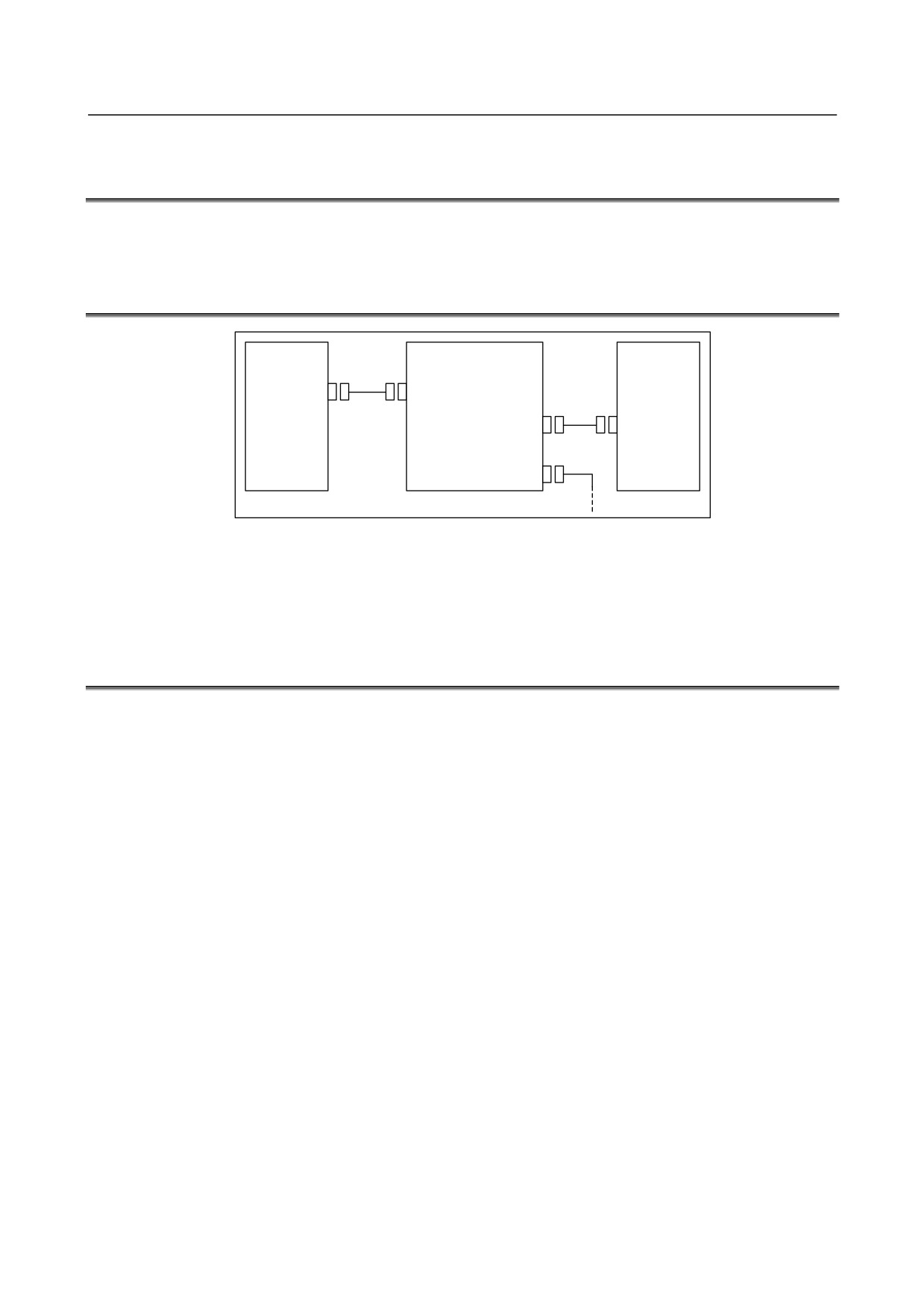
12. TWO-CHANNEL I/O Link
CONNECTOR ADAPTER
CONNECTION
B-61813E/06
12.6 CONNECTING THE TWO-CHANNEL I/O Link CONNECTOR
ADAPTER TO I/O UNITS
The 2-channel I/O Link connector adapter can be connected to diverse I/O Units in the same manner as for
the conventional FANUC I/O Link.
12.7 CABLE LENGTH
CNC unit
2-channel I/O Link
I/O Unit
connector adapter
JD44A/
LA
JD51A
JD44B
LB1
JD1A-1
JD1B
LB2
JD1A-2
The sum (LA + LB) of the cable length LA between the CNC unit (JD44A) and 2-channel I/O Link connector
adapter (JD44B) and the cable length LB between the I/O Link connector adapter (JD1A-1 or JD1A-2) and
I/O Unit (JD1B) shall not be longer than 10 m. For cabling within the same cabinet, the sum can be up to 15
m.
12.8 INSTALLING TWO-CHANNEL I/O Link CONNECTOR
ADAPTER
The two-channel I/O Link connector adapter needs to be installed in the cabinet containing the CNC unit.
- 174 -
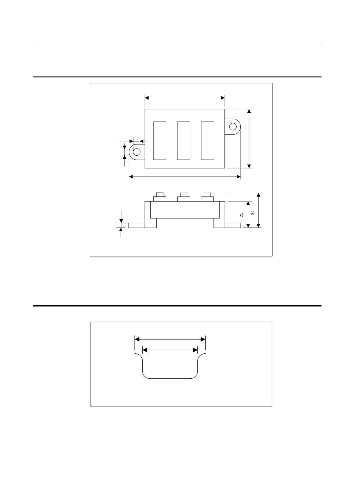
12. TWO-CHANNEL I/O Link
B-61813E/06
CONNECTION
CONNECTOR ADAPTER
12.9 OUTSIDE DIMENSIONS OF TWO-CHANNEL I/O Link
CONNECTOR ADAPTER
60
JD44B
JD1A-1
JD1A-2
5.1
45
4.1
81
4.5
Unit : mm
Allow a space of about 10 cm above the adapter so that cables can be laid and connected.
12.10 MOUNTING TWO-CHANNEL I/O Link CONNECTOR
ADAPTER
Mounting on the DIN rail
35
25
Unit: mm
Recommended DIN rail
- 175 -
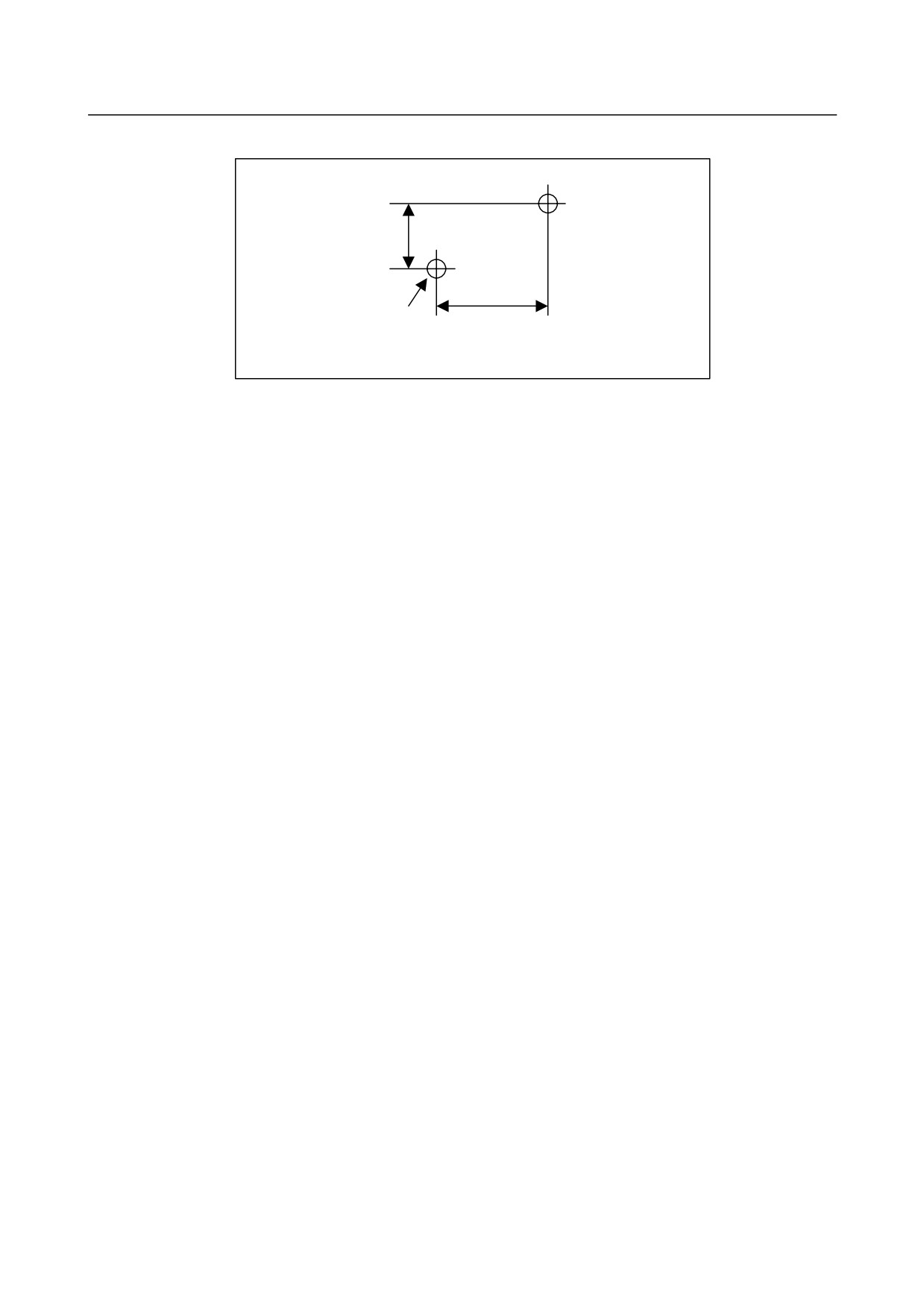
12. TWO-CHANNEL I/O Link
CONNECTOR ADAPTER
CONNECTION
B-61813E/06
Using screws
11.6
70
2-M4
Unit: mm
Mounting hole dimension and layout diagram
- 176 -
13.THREE-CHANNEL I/O Link
B-61813E/06
CONNECTION
CONNECTOR ADAPTER
13 THREE-CHANNEL I/O Link CONNECTOR
ADAPTER
13.1 OVERVIEW
With some i series CNC models, it is possible to use up to two I/O Link i interface channels and up to three
I/O Link interface channels. These channels make it possible to increase the number of I/O points to
4096/4096.
This chapter explains how to connect a 3-channel I/O Link connector adapter required in using the
3-channel function for I/O Link i or I/O Link.
NOTE
For the CNCs that can use this function, refer to the connection manual
(hardware) of each CNC.
For information on how to use this function, the PMC models that can use this
function, the series and edition of the PMC management software, and the series
and edition of the CNC management software, refer to the FANUC PMC LADDER
LANGUAGE PROGRAMMING MANUAL.
13.2 SPECIFICATION: A20B-1008-0360
Weight: 90g
13.3 CONNECTION FOR USE OF THREE FANUC I/O Link
CHANNELS
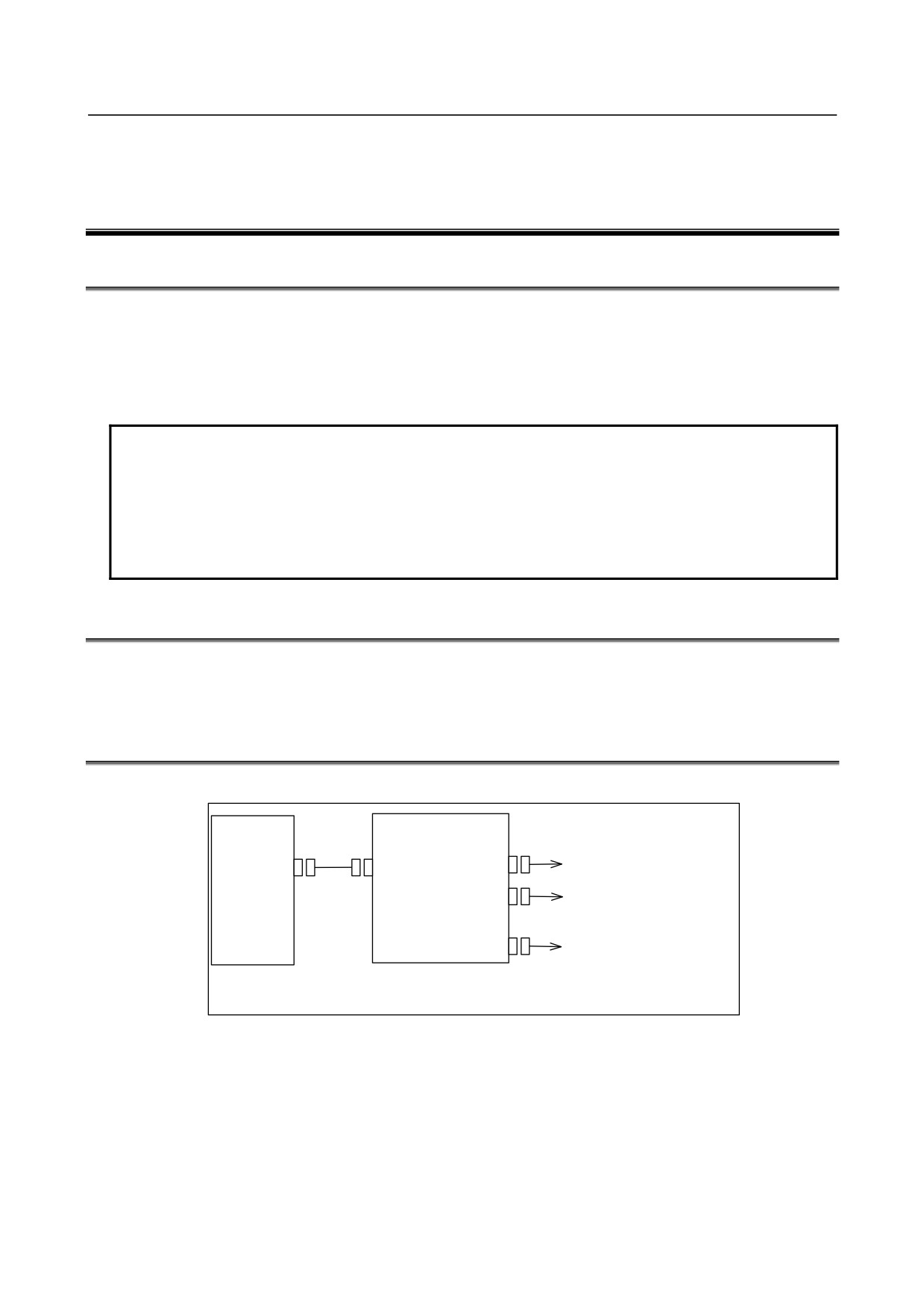
Connection
CNC unit
3-channel I/O Link
connector adapter
I/O Link i or I/O Link
JD51A
JD51B
JD44A-1
Channels 1 and 2
Channel 2 of I/O Link i or I/O
JD44A-2
Link
and channel 3 of I/O Link
JD1A
Channel 3 of I/O Link
Connections ahead of the 3-channel I/O Link connector adapter are
the same as for the conventional I/O Link i or I/O Link.
- 177 -
13. THREE-CHANNEL I/O Link
CONNECTOR ADAPTER
CONNECTION
B-61813E/06
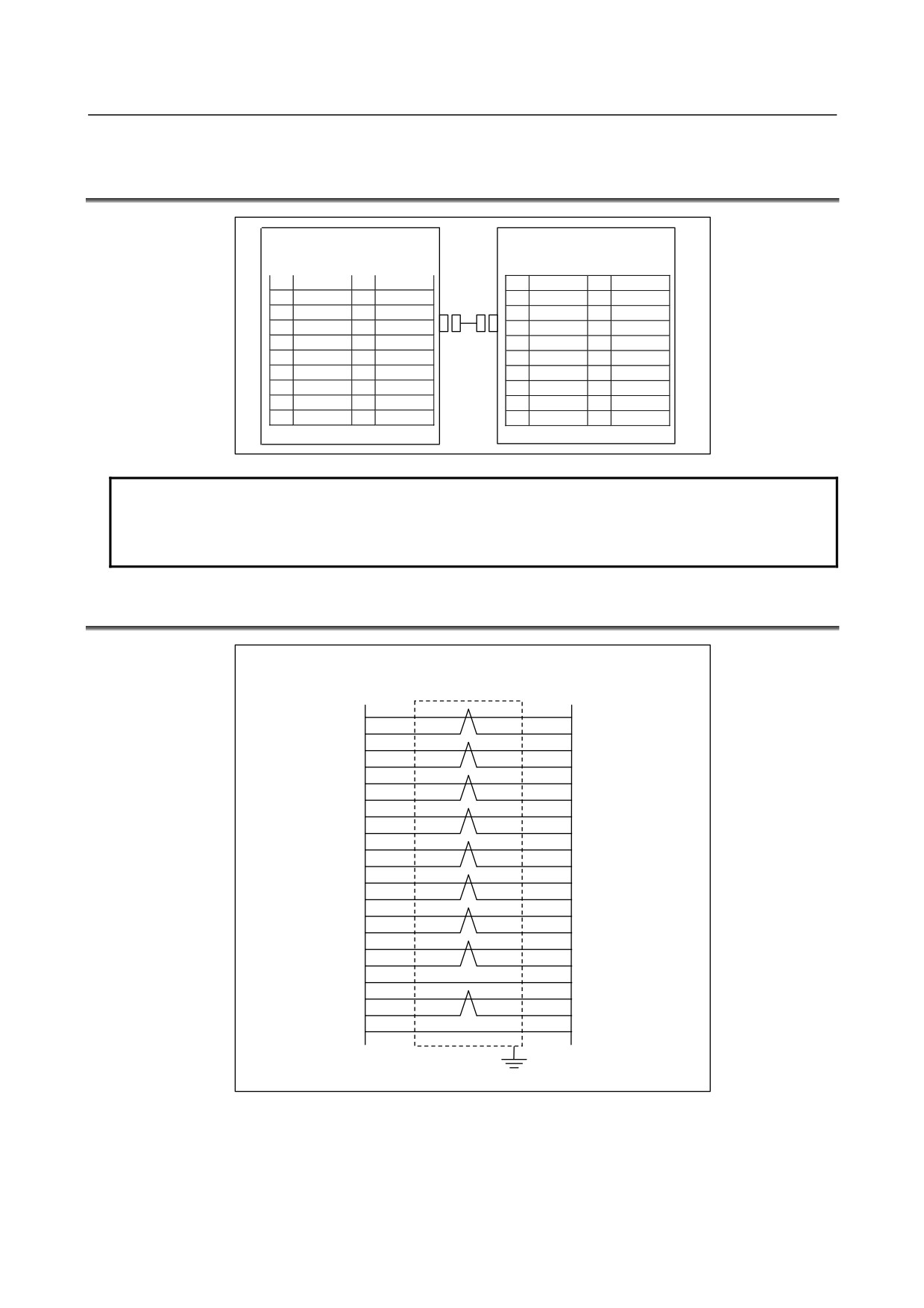
13.4 CONNECTING THE CNC WITH THREE-CHANNEL I/O Link
CONNECTOR ADAPTER
CNC unit
3-channel I/O Link connector
JD51A
adapter JD51B
(such as PCR-E20MDK-SL-A)
(PCR-E20MDT)
1
SIN1
11
0V
1
SIN1
11
0V
2
*SIN1
12
0V
2
*SIN1
12
0V
3
SOUT1
13
0V
3
SOUT1
13
0V
4
*SOUT1
14
0V
4
*SOUT1
14
0V
5
SIN2
15
0V
5
SIN2
15
0V
6
*SIN2
16
*SIN3
6
*SIN2
16
*SIN3
7
SOUT2
17
SIN3
7
SOUT2
17
SIN3
8
*SOUT2
18
(+5V)
8
*SOUT2
18
(+5V)
9
(+5V)
19
SOUT3
9
(+5V)
19
SOUT3
10
*SOUT3
20
(+5V)
10
*SOUT3
20
(+5V)
NOTE
The +5V pin enclosed in () is intended to supply power to an optical adapter for
connection through an optical fiber cable. When using no optical adapter, do not
connect the +5V pin.
13.5 CABLING
3-channel I/O Link
CNC unit
connector adapter
JD51A
JD51B
SIN1
1
3
SOUT1
*SIN1
2
4
*SOUT1
SOUT1
3
1
SIN1
*SOUT1
4
2
*SIN1
SIN2
5
7
SOUT2
*SIN2
6
8
*SOUT2
SOUT2
7
5
SIN2
*SOUT2
8
6
*SIN2
SIN3
17
19
SOUT3
*SIN3
16
10
*SOUT3
SOUT3
19
17
SIN3
*SOUT3
10
16
*SIN3
0V
11
11
0V
0V
12
12
0V
0V
13
13
0V
0V
14
14
0V
0V
15
15
0V
(+5V)
9
9
(+5V)
(+5V)
18
18
(+5V)
(+5V)
20
20
(+5V)
Shield
(*) When using no optical adapter, do not connect anything to the +5-V pin.
Recommended cable-end connector:
PCR-E20FA (manufactured by HONDA TSUSHIN)
FCN-247J020-G/E (manufactured by Fujitsu)
52622-2011 (manufactured by Molex)
Recommended cable (wire):
A66L-0001-0284#10P
- 178 -
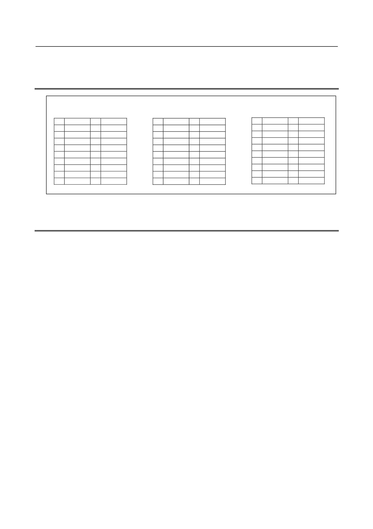
13.THREE-CHANNEL I/O Link
B-61813E/06
CONNECTION
CONNECTOR ADAPTER
13.6 ALLOCATING THREE-CHANNEL I/O Link CONNECTOR
ADAPTER SIGNALS
3-channel I/O Link connector
adapter JD44A-1
JD44A-2
JD1A
(PCR-E20MDT)
(PCR-E20MDT)
(PCR-E20MDT)
1
SIN1
11
0V
1
SIN2
11
0V
1
SIN3
11
0V
2
*SIN1
12
0V
2
*SIN2
12
0V
2
*SIN3
12
0V
3
SOUT1
13
0V
3
SOUT2
13
0V
3
SOUT3
13
0V
4
*SOUT1
14
0V
4
*SOUT2
14
0V
4
*SOUT3
14
0V
5
SIN2
15
0V
5
SIN3
15
0V
5
15
0V
6
*SIN2
16
0V
6
*SIN3
16
0V
6
16
0V
7
SOUT2
17
7
SOUT3
17
7
17
8
*SOUT2
18
(+5V)
8
*SOUT3
18
(+5V)
8
18
(+5V)
9
(+5V)
19
9
(+5V)
19
9
(+5V)
19
10
20
(+5V)
10
20
(+5V)
10
20
(+5V)
13.7 CONNECTING THE THREE-CHANNEL I/O Link
CONNECTOR ADAPTER TO I/O UNITS
The 3-channel I/O Link connector adapter can be connected to each I/O Unit in the same manner as for the
I/O Link i or I/O Link. However, note the following points:
Signals on channels 1 and 2 of I/O Link i and I/O Link are allocated to the JD44A-1. Signals on channel 2 of
I/O Link i and I/O Link and those on channel 3 of I/O Link are allocated to the JD44A-2.
The JD1A connector is dedicated to I/O Link channel 3.
(1) To branch out the 3-channel signals, an ordinary I/O Link cable is connected to each of the JD44A-1,
JD44A-2, and JD1A. In this case, the JD44A-1, JD44A-2, and JD1A correspond, respectively, to
channels 1, 2, and 3.
(2) To extend channels 1 and 2 together, the 2-channel I/O Link connector adapter is connected to the
JD44A-1 to separate channels 1 and 2 from each other after the adapter.
To use channel 3, connect it to the JD1A; the JD44A-2 cannot be used.
(3) To extend channels 2 and 3 together, the 2-channel I/O Link connector adapter is connected to the
JD44A-2 to separate channels 2 and 3 from each other after the adapter.
To use channel 1, connect it to the JD44A-1; the JD1A cannot be used.
- 179 -
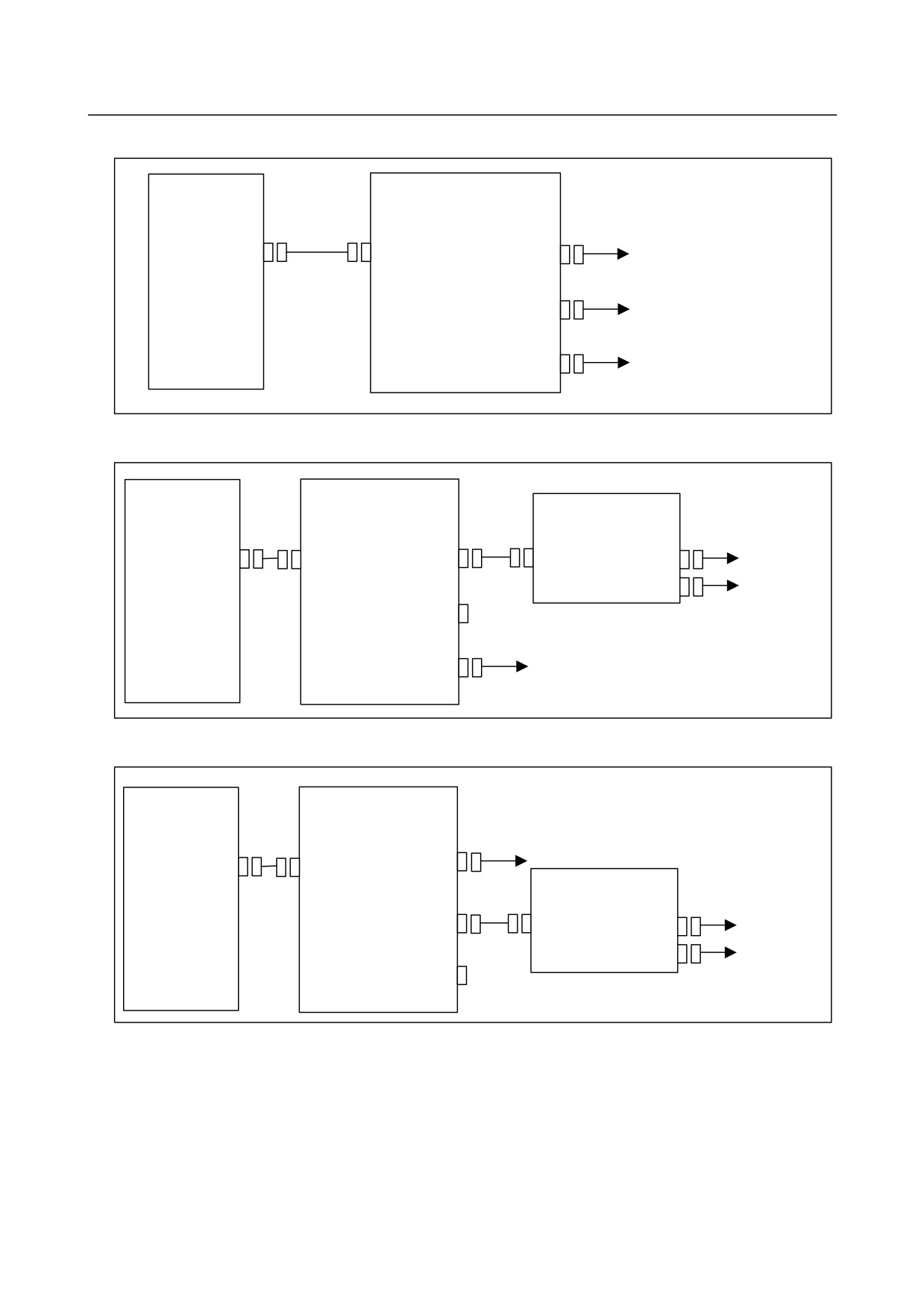
13. THREE-CHANNEL I/O Link
CONNECTOR ADAPTER
CONNECTION
B-61813E/06
(1) When branching out the 3-channel signals
CNC
3-channel I/O Link
connector adapter
JD51A
JD51B
JD44A-1
Channel 1
Channel 2
JD44A-2
JD1A
Channel 3
(2) When extending channels 1 and 2 together
CNC
3-channel I/O Link
2-channel I/O Link
connector adapter
connector adapter
JD51A
JD51B
JD44A-1
JD44B
JD1A-1
Channel 1
JD1A-2
Channel 2
Unusable
JD44A-2
JD1A
Channel 3
(3) When extending channels 2 and 3 together
CNC
3-channel I/O Link
connector adapter
Channel 1
JD51A
JD51B
JD44A-1
2-channel I/O Link
connector adapter
JD44A-2
JD44B
JD1A-1
Channel 2
JD1A-2
Channel 3
JD1A
Unusable
- 180 -
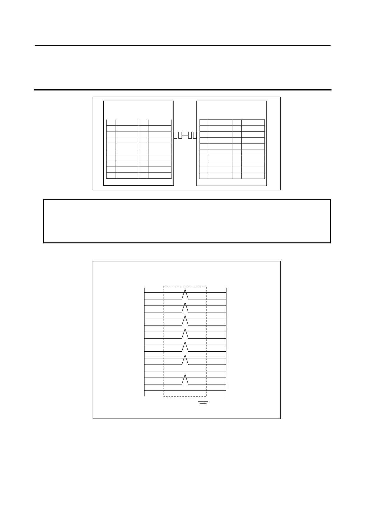
13.THREE-CHANNEL I/O Link
B-61813E/06
CONNECTION
CONNECTOR ADAPTER
13.8 CONNECTING THREE-CHANNEL I/O Link CONNECTOR
ADAPTER TO TWO-CHANNEL I/O Link CONNECTOR
ADAPTER
3-channel I/O Link connector
2-channel I/O Link connector
adapter JD44A-1/ JD44A-2
adapter JD44B
(such as PCR-E20MDK-SL-A)
(PCR-E20MDT)
1
SIN1
11
0V
1
SIN1
11
0V
2
*SIN1
12
0V
2
*SIN1
12
0V
3
SOUT1
13
0V
3
SOUT1
13
0V
4
*SOUT1
14
0V
4
*SOUT1
14
0V
5
SIN2
15
0V
5
SIN2
15
0V
6
*SIN2
16
6
*SIN2
16
7
SOUT2
17
7
SOUT2
17
8
*SOUT2
18
(+5V)
8
*SOUT2
18
(+5V)
9
(+5V)
19
9
(+5V)
19
10
20
(+5V)
10
20
(+5V)
NOTE
1 The +5V pin enclosed in () is intended to supply power to an optical adapter for
connection through an optical fiber cable. When using no optical adapter, do not
connect the +5V pin.
2 Do not connect anything to pins to which no signal is assigned.
Cabling
3-channel I/O Link
2-channel I/O Link
connector adapter
connector adapter
JD44A-1
JD44B
SIN1
1
3
SOUT1
*SIN1
2
4
*SOUT1
SOUT1
3
1
SIN1
*SOUT1
4
2
*SIN1
SIN2
5
7
SOUT2
*SIN2
6
8
*SOUT2
SOUT2
7
5
SIN2
*SOUT2
8
6
*SIN2
0V
11
11
0V
0V
12
12
0V
0V
13
13
0V
0V
14
14
0V
0V
15
15
0V
(+5V)
9
9
(+5V)
(+5V)
18
18
(+5V)
(+5V)
20
20
(+5V)
Shield
(*) When using no optical adapter, do not connect anything to the +5-V pin.
Recommended cable-end connector:
PCR-E20FA (manufactured by HONDA TSUSHIN)
FCN-247J020-G/E (manufactured by Fujitsu)
52622-2011 (manufactured by Molex)
Recommended cable (wire):
A66L-0001-0284#10P
- 181 -
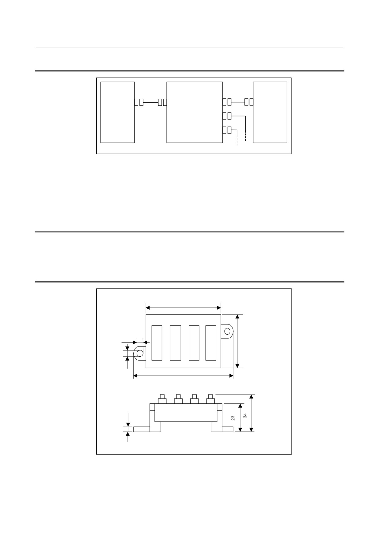
13. THREE-CHANNEL I/O Link
CONNECTOR ADAPTER
CONNECTION
B-61813E/06
13.9 CABLE LENGTH
CNC unit
3-channel I/O Link
I/O Unit
connector adapter
LA
JD51B
JD44A-1
LB1
JD1B
JD51A
LB2
JD44A-2
LB3
JD1A
The sum (LA + LB) of the cable length LA between the CNC unit (JD51A) and I/O Link connector adapter
(JD51B) and the cable length LB between the I/O Link connector adapter (JD44A-1, JD44A-2, or JD1A)
and I/O Unit (JD1B) shall not be longer than 10 m. For cabling within the same cabinet, the sum can be up
to 15 m.
13.10 INSTALLING THREE-CHANNEL I/O Link CONNECTOR
ADAPTER
The three-channel I/O Link connector adapter needs to be installed in the cabinet containing the CNC unit.
13.11 OUTSIDE DIMENSIONS OF THREE-CHANNEL I/O Link
CONNECTOR ADAPTER
80
JD51B
JD44A-1 JD44A-2
JD1A
5.1
45
4.1
101
4.5
Unit: mm
Allow a space of about 10 cm above the adapter so that cables can be laid and connected.
- 182 -
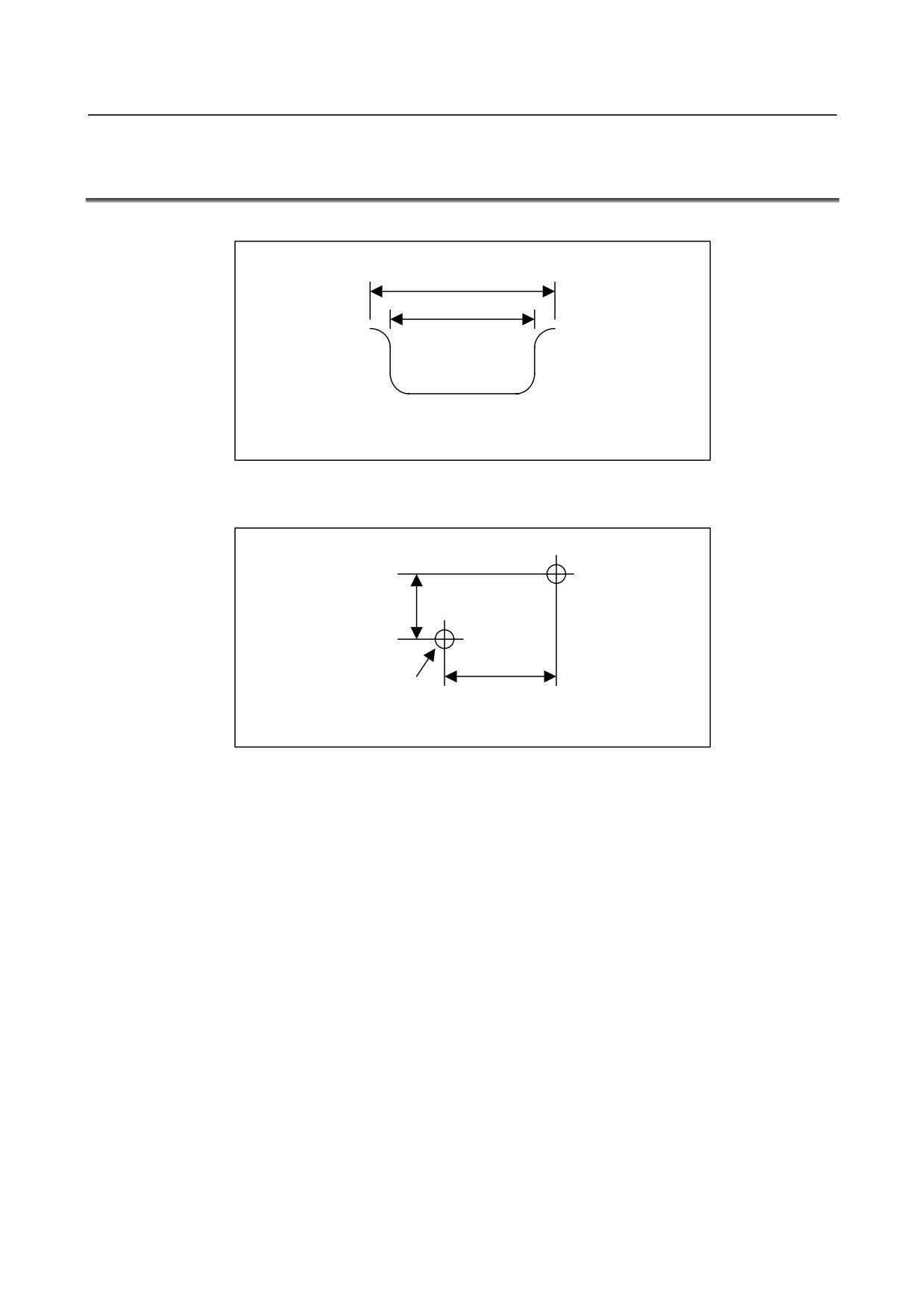
13.THREE-CHANNEL I/O Link
B-61813E/06
CONNECTION
CONNECTOR ADAPTER
13.12 MOUNTING THREE-CHANNEL I/O Link CONNECTOR
ADAPTER
Mounting on the DIN rail
35
25
Unit: mm
Recommended DIN rail
Using screws
11.6
90
2-M4
Unit: mm
Mounting hole dimension and layout diagram
- 183 -
14.SAFETY FOR USING AC
CONNECTION
B-61813E/06
14 SAFETY FOR USING AC
IF AC output module or AC input module is used, Section 14.1 is recommended for safety. When using it
for a machine directed to the European market, carefully observe the descriptions in Section 14.1 [as per
EN50178].
14.1 ENVIRONMENT FOR INSTALLATION
14.1.1 Installation Category (Overvoltage Category)
Install the unit in the environment of Installation Category II
(Overvoltage Category II) or better.
[EN50178]
The available impulse surge level to the ground that appears in the power source is 2.5kV maximum.
(100VAC system power source is needed in AC input module According to the standard, the available
impulse surge level to the ground is 1.5kV for this power source (voltage of which is 150VAC or less).
However, for this module, the available impulse surge level to the ground that appears in the power source
is 2.5 kV.)
Generally, an isolation transformer used for the main power source is regarded as an effective surge filter.
The class of the 16-point relay output module (AOR16G) is set to installation category (overvoltage
category) I.
(Keep any impulse voltage to ground that may appear on the AC power to within 1.5 kV.)
The class for the 8-point relay output module (AOR08G), AC output module, and AC input module is set to
installation category (overvoltage category) II.
WARNING
Connect the same phase of a power source to the commons of the AC input and
AC output modules. Otherwise, burnout or fire may occur.
NOTE
1 The AC output module incorporates a 3.2 A fuse per common. It is assumed that,
if the load is short-circuited, the fuse blows to protect the triac. However, be
sufficiently careful not to cause a short circuit because no little damage occurs to
the triac when the fuse blows.
2 If external AC input lines run through a long omnibus cable, inter-wire mutual
capacitances may cause induced current to flow from live lines to open lines,
leading to an ON state. If this is the case, a typical measure might be to lower the
input impedance by attaching a bleeder resistance between the input pins.
3 If a reed switch is used as the input contact of the AC input module, the reed
switch must be one having a permissible current capacity of 1 A or higher.
Otherwise rush current may cause the contact to be welded.
14.1.2 Pollution Degree
Install the unit in the environment of pollution degree 2 or better. [EN50178]
In cabinet of IP-54 or better (described in Section 3.1), it can be considered as pollution degree 2 or better
usually. The IP degree required is depended on the circumstances of machine tool, so select the adequate
degree in accordance with such environment.
- 184 -