FANUC Series 0i-MODEL C, Series 0i Mate-MODEL C. PARAMETER MANUAL (B-64120EN/01) - page 11
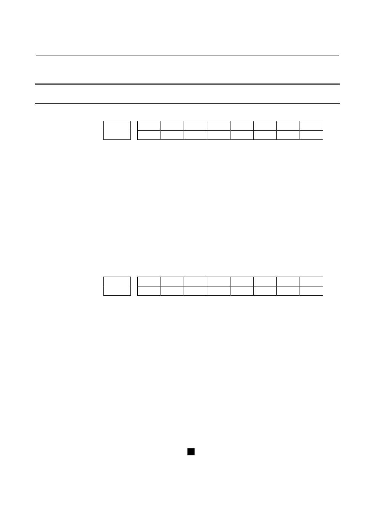
4.DESCRIPTION OF PARAMETERS
B-64120EN/01
#7
#6
#5
#4
#3
#2
#1
#0
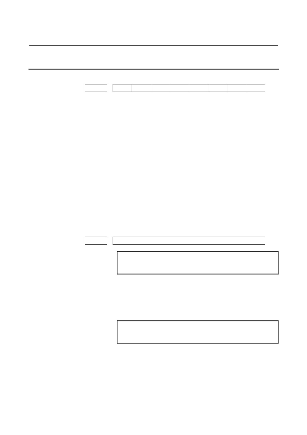
6010
*7
*6
*5
*4
*3
*2
*1
*0
#7
#6
#5
#4
#3
#2
#1
#0
6011
=7
=6
=5
=4
=3
=2
=1
=0
#7
#6
#5
#4
#3
#2
#1
#0
6012
#7
#6
#5
#4
#3
#2
#1
#0
#7
#6
#5
#4
#3
#2
#1
#0
6013
[7
[6
[5
[4
[3
[2
[1
[0
#7
#6
#5
#4
#3
#2
#1
#0
6014
]7
]6
]5
]4
]3
]2
]1
]0
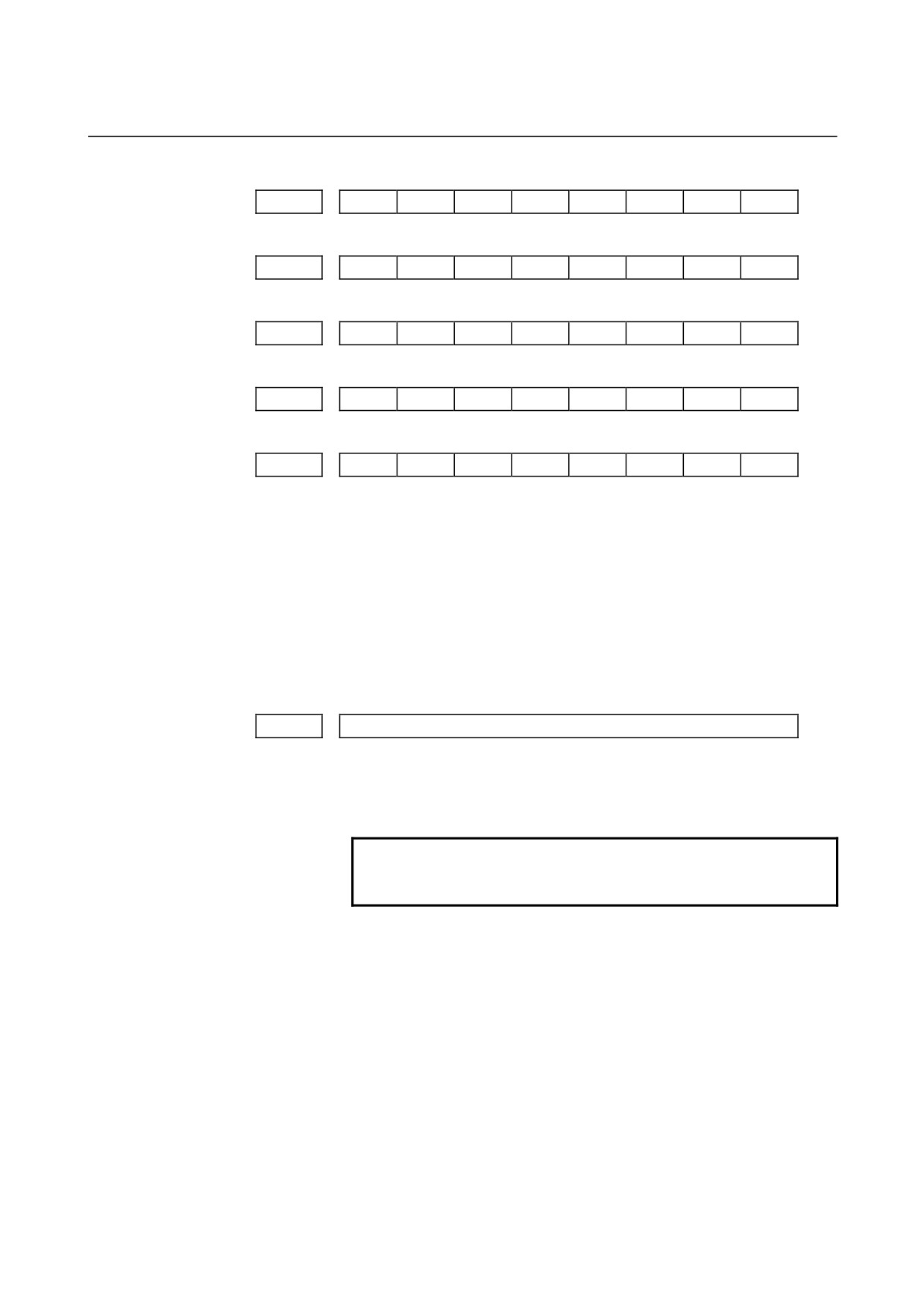
[Data type]
Bit
These parameters are used for input/output with EIA codes.
The numeral of a suffix indicates the bit position in a code.
*0 to *7 : Set the hole pattern of an EIA code indicating *.
=0 to =7 : Set the hole pattern of an EIA code indicating =.
#0 to #7 : Set the hole pattern of an EIA code indicating #.
[ 0 to [ 7 : Set the hole pattern of an EIA code indicating [.
] 0 to ] 7 : Set the hole pattern of an EIA code indicating ].
0 : Corresponding bit is 0
1 : Corresponding bit is 1.
6030
M code that calls the program entered in file
[Data type]
2-word
[Valid data range]
0, and 1 to 255
This parameter sets an M code that calls the program entered in a file.
NOTE
The M code is judged to be M198 when zero is
specified as the setting value.
- 292 -
B-64120EN/01
4.DESCRIPTION OF PARAMETERS
6033
M code that validates a custom macro interrupt
6034
M code that invalidates a custom macro interrupt
[Data type]
2-word
[Valid data range]
0 to 255
These parameters set the custom macro interrupt valid/invalid
M
codes.
NOTE
These parameters can be used when MPR, #4 of
parameter No.6003, is 1. M96 is used as a valid M
code and M97 is used as an invalid M code when
MPR is 0, irrespective of the state of this
parameter.
6050
G code that calls the custom macro of program number 9010
6051
G code that calls the custom macro of program number 9011
6052
G code that calls the custom macro of program number 9012
6053
G code that calls the custom macro of program number 9013
6054
G code that calls the custom macro of program number 9014
6055
G code that calls the custom macro of program number 9015
6056
G code that calls the custom macro of program number 9016
6057
G code that calls the custom macro of program number 9017
6058
G code that calls the custom macro of program number 9018
6059
G code that calls the custom macro of program number 9019
[Data type]
Word
[Valid data range]
1 to 9999
These parameters set the G codes that call the custom
macros of
program numbers 9010 through 9019.
NOTE
Setting value 0 is invalid. No custom macro can be
called by G00.
- 293 -
4.DESCRIPTION OF PARAMETERS
B-64120EN/01
6071
M code that calls the subprogram of program number 9001
6072
M code that calls the subprogram of program number 9002
6073
M code that calls the subprogram of program number 9003
6074
M code that calls the subprogram of program number 9004
6075
M code that calls the subprogram of program number 9005
6076
M code that calls the subprogram of program number 9006
6077
M code that calls the subprogram of program number 9007
6078
M code that calls the subprogram of program number 9008
6079
M code that calls the subprogram of program number 9009
[Data type]
2-word
[Valid data range]
1 to 99999999
These parameters set the M codes that call the subprograms
of
program numbers 9001 through 9009.
NOTE
Setting value 0 is invalid. No subprogram can be
called by M00.
- 294 -
B-64120EN/01
4.DESCRIPTION OF PARAMETERS
6080
M code that calls the custom macro of program number 9020
6081
M code that calls the custom macro of program number 9021
6082
M code that calls the custom macro of program number 9022
6083
M code that calls the custom macro of program number 9023
6084
M code that calls the custom macro of program number 9024
6085
M code that calls the custom macro of program number 9025
6086
M code that calls the custom macro of program number 9026
6087
M code that calls the custom macro of program number 9027
6088
M code that calls the custom macro of program number 9028
6089
M code that calls the custom macro of program number 9029
[Data type]
2-word
[Valid data range]
1 to 99999999
These parameters set the M codes that call the custom macros of
program numbers 9020 through 9029.
NOTE
Setting value 0 is invalid. No custom macro can be
called by M00.
6090
ASCII code that calls the subprogram of program number 9004
6091
ASCII code that calls the subprogram of program number 9005
NOTE
When this parameter is set, the power must be
turned off before operation is continued.
[Data type]
Byte
[Valid data range]
65 (A:41H) to 90 (Z:5AH)
These parameters set the ASCII codes that call subprograms
in
decimal.
Addresses that can be used are as follows:
T series : A, B, F, H, I, K, M, P, Q, R, S, T
M series: A, B, D, F, H, I, J, K, L, M, P, Q, R, S, T, X, Y, Z
NOTE
Set 0 when no subprogram is called
- 295 -

4.DESCRIPTION OF PARAMETERS
B-64120EN/01
4.30
PARAMETERS OF PATTERN DATA INPUT
6101
First variable number displayed on pattern data screen 1
6102
First variable number displayed on pattern data screen 2
6103
First variable number displayed on pattern data screen 3
6104
First variable number displayed on pattern data screen 4
6105
First variable number displayed on pattern data screen 5
6106
First variable number displayed on pattern data screen 6
6107
First variable number displayed on pattern data screen 7
6108
First variable number displayed on pattern data screen 8
6109
First variable number displayed on pattern data screen 9
6110
First variable number displayed on pattern data screen 10
[Data type] Word
[Valid data range]
0, 100 to 199, 500 to 999
These parameters specify the first variable number displayed on the
pattern data screen selected from the pattern menu screen. When 0 is
set, 500 is assumed.
- 296 -

B-64120EN/01
4.DESCRIPTION OF PARAMETERS
4.31
PARAMETERS OF SKIP FUNCTION
#7
#6
#5
#4
#3
#2
#1
#0
SKF
SRE
SLS
HSS
MIT
SK0
GSK
6200
SKF
SRE
SLS
HSS
SK0
[Data type]
Bit
GSK
In skip cutting (G31), the skip signal SKIPP <G006#6> is:
0 : Not used as a skip signal.
1 : Used as a skip signal.
SK0
This parameter specifies whether the skip signal is made valid under
the state of the skip signal SKIP <X004#7> and the multistage skip
signals <X004#0-7> (for the T series only).
0 : Skip signal is valid when these signals are 1.
1 : Skip signal is valid when these signals are 0.
MIT
In skip cutting (G31), the tool compensation measurement value direct
input B signals +MIT1, -MIT1, +MIT2, and -MIT2 <X004#2-5> are :
0 : Not used as skip signals.
1 : Used as skip signals.
HSS
0 : The skip function does not use high-speed skip signals.
1 : The skip function uses high-speed skip signals.
SLS
0
The multi-step skip function does not use high-speed skip signals
while skip signals are input.
1 : The multi-step skip function uses high-speed skip signals while
skip signals are input.
SRE
When a high-speed skip signal is used:
0 : The signal is considered to be input at the rising edge (0#1).
1 : The signal is considered to be input at the falling edge (1#0).
SKF
Dry run, override, and automatic acceleration/deceleration for G31
skip command
0 : Disabled
1 : Enabled
#7
#6
#5
#4
#3
#2
#1
#0
6201
SPE
IGX
TSA
TSE
SEB
SEA
[Data type]
Bit
SEA
When a high speed skip signal goes on while the skip function is used,
acceleration/deceleration and servo delay are:
0 : Ignored.
1 : Considered and compensated (type A).
SEB
When a high speed skip signal goes on while the skip function is used,
acceleration/deceleration and servo delay are:
0 : Ignored.
1 : Considered and compensated (type B).
- 297 -
4.DESCRIPTION OF PARAMETERS
B-64120EN/01
NOTE
There are two types of compensation: Types A and
B. With the skip function, the current position is
stored in the CNC according to the skip signal.
However, the current position stored in the CNC
contains servo delay. The machine position is
therefore deviated by the servo delay. The
deviation can be obtained from the position
deviation of the servo and the error generated due
to feedrate acceleration/deceleration performed by
the CNC. If the deviation can be compensated, it is
not necessary to include the servo delay in
measurement errors. The deviation can be
compensated with the following two types by the
parameter as follows:
(1) Type A: The deviation is the value calculated
from the cutting time constant and
servo time constant (loop gain).
(2) Type B: The deviation is the error due to
acceleration/deceleration and the
position deviation when the skip
signal goes on.
TSE
When the torque limit skip function (G31 P99/98) is used, the skip
position held in a system variable is:
0 : Position that is offset considering the delay (positional deviation)
incurred by the servo system.
1 : Position that does not reflect the delay incurred by the servo
system.
NOTE
The torque limit skip function stores the current
position in the CNC when the torque limit arrival
signal is turned on. However, the current position in
the CNC includes a servo system delay, so that the
position is shifted from the machine position by an
amount corresponding to the servo system delay.
The value of this shift can be determined from the
servo system positional deviation. When TSE is set
to 0, a skip position is determined by subtracting
the positional deviation from the current position.
When TSE is set to 1, the current position
(including the servo system delay) is used as the
skip position, without considering any shift or
position deviation.
- 298 -

B-64120EN/01
4.DESCRIPTION OF PARAMETERS
TSA
When the torque limit skip function (G31 P99/98) is used, torque limit
arrival monitoring is performed for:
0 : All axes.
1 : Only those axes that are specified in the block containing the
G31 command.
IGX
When the high-speed skip function is used, SKIP <X004#7>, SKIPP
<G006#6>, and +MIT1 to -MIT2 <X004#2-5> are:
0 : Enabled as skip signals.
1 : Disabled as skip signals.
NOTE
1 SKIPP <G006#6> and +MIT1 to -MIT2
<X004#2-5> are enabled only when bit 0 (GSK) of
parameter No.6200 is set to 1 and bit 3 (MIT) of
parameter No.6200 is set to 1. Note also that these
signals are enabled only for the T series.
2 The skip signals for the multistage skip function
(SKIP, SKIP2 to SKIP8) can also be disabled.
SPE
For the skip function (G31), the skip signal <X004#7> is:
0 : Disabled.
1 : Enabled.
#7
#6
#5
#4
#3
#2
#1
#0
6202
1S8
1S7
1S6
1S5
1S4
1S3
1S2
1S1
#7
#6
#5
#4
#3
#2
#1
#0
6203
2S8
2S7
2S6
2S5
2S4
2S3
2S2
2S1
#7
#6
#5
#4
#3
#2
#1
#0
6204
3S8
3S7
3S6
3S5
3S4
3S3
3S2
3S1
#7
#6
#5
#4
#3
#2
#1
#0
6205
4S8
4S7
4S6
4S5
4S4
4S3
4S2
4S1
#7
#6
#5
#4
#3
#2
#1
#0
6206
DS8
DS7
DS6
DS5
DS4
DS3
DS2
DS1
[Data type]
Bit
1S1 to 1S8
Specify which high-speed skip signal is enabled when the G31 skip
command is issued. The bits correspond to the following signals:
1S1
HDI0
1S2
HDI1
1S3
HDI2
1S4
HDI3
1S1 to 1S8, 2S1 to 2S8, 3S1 to 3S8, 4S1 to 4S8, DS1 to DS8
Specify which skip signal is enabled when the skip command (G31, or
G31P1 to G31P4) and the dwell command (G04, G04Q1 to G04Q4)
are issued with the multi-step skip function.
- 299 -
4.DESCRIPTION OF PARAMETERS
B-64120EN/01
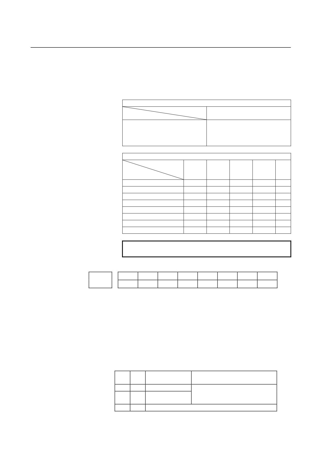
The following table shows the correspondence between the bits, input
signals, and commands.
The setting of the bits have the following meaning :
0 : The skip signal corresponding to the bit is disabled.
1 : The skip signal corresponding to the bit is enabled.
High-speed skip function
Command
G31
Input signal
HDI0
1S1
HDI1
1S2
HDI2
1S3
HDI3
1S4
Multi-step skip function
Command
G31
G31P2
G31P2
G31P4
G04
G31P1
G04Q2
G04Q2
G04Q4
Input signal
G04Q1
SKIP/HDI0
1S1
2S1
3S1
4S1
DS1
SKIP2/HDI1
1S2
2S2
3S2
4S2
DS2
SKIP3/HDI2
1S3
2S3
3S3
4S3
DS3
SKIP4/HDI3
1S4
2S4
3S4
4S4
DS4
SKIP5
1S5
2S5
3S5
4S5
DS5
SKIP6
1S6
2S6
3S6
4S6
DS6
SKIP7
1S7
2S7
3S7
4S7
DS7
SKIP8
1S8
2S8
3S8
4S8
DS8
NOTE
HDI0 to HDI3 are high-speed skip signals.
#7
#6
#5
#4
#3
#2
#1
#0
ROS
6210
ASB
ASL
ROS
[Data type]
Bit
ROS
When the skip position goes beyond the roll-over range, the values of
system variables
#5061 through #5068 indicating the skip signal
position:
0 : Are not rolled over.
1 : Are rolled over similar to the absolute coordinates.
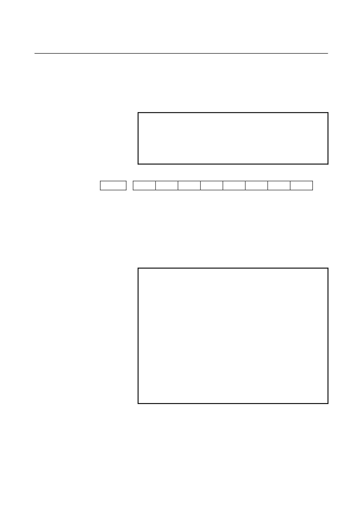
ASB, ASL
Set the type and time constant of acceleration/deceleration after
interpolation for the skip function in advanced preview control, AI
advanced preview control, or AI contour control mode as listed below.
Acceleration/
ASB
ASL
Parameter No. of time constant
deceleration type
0
1
Linear
Parameter No. 6280
(If 0 is set, the value in parameter No.
1
-
Bell-shaped
1769 (1768) is used.)
0
0
This function is disabled. (See NOTE.)
- 300 -
B-64120EN/01
4.DESCRIPTION OF PARAMETERS
When bell-shaped acceleration/deceleration is specified, the following
equations hold as with ordinary bell-shaped acceleration/deceleration
after cutting feed interpolation, where T denotes the time constant:
T1=T/2, T2=T/2. Therefore, an acceleration/deceleration type
containing no linear part is set.
NOTE
If ASB is set to 0, and ASL is set to 0, the
acceleration/deceleration type is set by bit 3 (BS2)
of parameter No.1602 and bit 6 (LS2) of parameter
No. 1602, and the time constant set in parameter
No. 1762, 768, or 1769 is used.
#7
#6
#5
#4
#3
#2
#1
#0
6215
CSTx
[Data type]
Bit axis
CSTx
For the Cs contour controlled axis, the torque limit skip function is:
0 : Disabled.
1 : Enabled.
Torque limit skip operation is performed for the Cs counter controlled
axis by using the serial spindle torque limit command signal
TLMH<G070,G074> and the load detection
signal
LDT1<F045,F049>.
NOTE
When this parameter is set to perform torque limit
skip operation for a Cs counter controlled axis, note
the following:
1 For the Cs contour controlled axis (spindle) that
uses the torque limit skip function, set bit 4 of
serial spindle parameter No. 4009 to 1 so that
load detection signals are output even during
acceleration/deceleration.
2 If the load detection state (LDT1 = 1) is set when
the torque limit command is specified (TLMH1 =
1) in the Cs mode, no excessive error check at
stop is performed for the axis.
3 If the load detection state (LDT1 = 1) is set in
the Cs mode, no in-position check is made for
the axis.
- 301 -
4.DESCRIPTION OF PARAMETERS
B-64120EN/01
Time from the specification of a torque limit skip until the skip operation is
6221
enabled
[Data type] Word
[Unit of data] ms
[Valid data range]
0 to 65535
Set a time from the specification of a torque limit skip until the skip
operation is enabled. Within the set time, the skip operation is not
performed.
- 302 -
B-64120EN/01
4.DESCRIPTION OF PARAMETERS
4.32 PARAMETERS OF AUTOMATIC TOOL COMPENSATION
(T SERIES) AND AUTOMATIC TOOL LENGTH
COMPENSATION (M SERIES)
#7
#6
#5
#4
#3
#2
#1
#0
6240
AE0
[Data type]
Bit
AE0
Measurement position arrival is assumed when the automatic tool
compensation signals XAE and ZAE <X004#0,1> (T series) or the
automatic tool length measurement signals XAE, YAE, and ZAE
<X004#0-2> (M series) are:
0 :
1
1 :
0
Feedrate during measurement of automatic tool compensation
6241
Feedrate during measurement of automatic tool length compensation
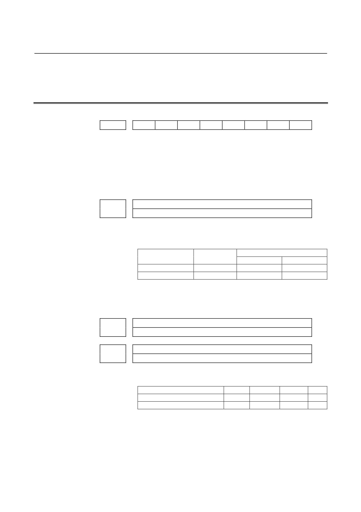
[Data type]
Word
[Unit of data, valid data range]
Valid data range
Increment system
Units of data
IS-A, IS-B
IS-C
Millimeter machine
1 mm/min
6 to 15000
6 to 12000
Inch machine
0.1 inch/min
6 to 6000
6 to 4800
This parameter sets the feedrate during measurement of automatic tool
compensation (T series) and automatic tool length compensation (M
series).
γ value on X axis during automatic tool compensation
6251
γ value during automatic tool length automatic compensation
γ value on Z axis during automatic tool compensation
6252
[Data type]
2-word
[Unit of data]
Input increment
IS-A
IS-B
IS-C
Unit
Millimeter input
0.01
0.001
0.0001
mm
Inch input
0.001
0.0001
0.00001
inch
[Valid data range]
1 to 99999999
These parameters set the γ value during automatic tool compensation
(T series) or tool length automatic compensation (M series).
- 303 -
4.DESCRIPTION OF PARAMETERS
B-64120EN/01
NOTE
Set a radius value irrespective of whether the
diameter programming or the radius programming
is specified.
ε value on X axis during automatic tool compensation
6254
ε value during automatic tool length automatic compensation
ε value on Z axis during automatic tool compensation
6255
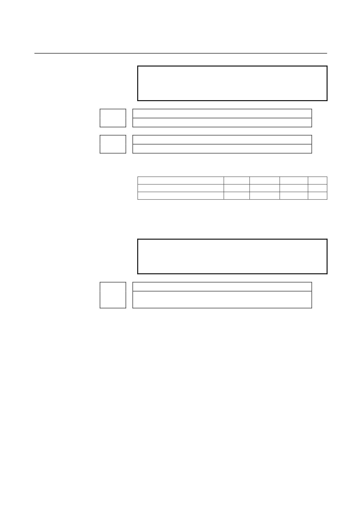
[Data type]
2-word
[Unit of data]
Input increment
IS-A
IS-B
IS-C
Unit
Millimeter input
0.01
0.001
0.0001
mm
Inch input
0.001
0.0001
0.00001
inch
[Valid data range]
1 to 99999999
These parameters set the ε value during automatic tool compensation
(T series) or automatic tool length offset (M series).
NOTE
Set a radius value irrespective of whether the
diameter programming or the radius programming
is specified.
Time constant of acceleration/deceleration after interpolation in the skip
6280
function in advanced preview control, AI advanced preview control, or AI
contour control mode for each axis
[Data type] Word axis
[Unit of data] msec
[Valid data range]
0 to 512
This parameter sets the time constant of acceleration/deceleration after
interpolation in the skip function in advanced preview control, AI
advanced preview control, or AI contour control mode for each axis.
This parameter is valid when bit 3 (ASL) of parameter No. 6210 is set
to 1. (See the description of bit 3 (ASL) of parameter No. 6210.)
If this parameter is set to 0, the value set in parameter No. 1769 is
used. If parameter No. 1769 is set also to 0, the value in parameter No.
1768 is used.
- 304 -
B-64120EN/01
4.DESCRIPTION OF PARAMETERS
4.33
PARAMETERS OF EXTERNAL DATA INPUT/OUTPUT
#7
#6
#5
#4
#3
#2
#1
#0
6300
EEX
ESR
ESC
[Data type]
Bit
ESC
When a reset is input between input of the external data input read
signal ESTB
<G002#7> and execution of a search, the external
program number search function:
0 : Performs a search.
1 : Does not perform a search.
ESR
External program number search
0 : Disabled
1 : Enabled
EEX
PMC EXIN function
0 : Conventional specifications
1 : Extended specifications
If you want to handle data unavailable with the PMC/EXIN command
according to the conventional specifications, such as an
8-digit
program number, in an external program number search, set this bit to
1.
To use this function for multipath control, the setting for the first path
(main) is used. The EXIN specifications cannot be changed for each
path. For details of EXIN and how to change ladder software, refer to
the PMC specifications and other manuals.
6310
Number of added message numbers of external operator messages
NOTE
When this parameter is set, the power must be
turned off before operation is continued.
[Data type]
Word
[Valid data range]
0, 1 to 1000
For external operator messages within the range set in this parameter,
message numbers each obtained by adding
2000 to the relevant
message number are indicated.
NOTE
If 0 or a value beyond the valid data range is set in
this parameter, this parameter becomes invalid.
- 305 -
4.DESCRIPTION OF PARAMETERS
B-64120EN/01
4.34
PARAMETERS OF GRAPHIC DISPLAY
4.34.1
Parameters of Graphic Display/Dynamic Graphic Display
#7
#6
#5
#4
#3
#2
#1
#0
NZM
DPA
6500
DPO
[Data type]
Bit
DPA
Current position display on the graphic display screen
0 : Displays the actual position to ensure tool nose radius
compensation
1 : Displays the programmed position
DPO
Current position on the solid drawing (machining profile drawing) or
tool path drawing screen
0 : Not appear
1 : Appears
NZM
0 : The screen image is not enlarged by specifying the center of the
screen and magnification.
(Screen image enlargement by a
conventional method is enabled.)
1 : The screen image is enlarged by specifying the center of the
screen and magnification.
#7
#6
#5
#4
#3
#2
#1
#0
CSR
6501
CSR
FIM
RID
3PL
TLC
ORG
[Data type]
Bit
ORG
Movement when coordinate system is altered during drawing
0 : Draws in the same coordinate system
1 : Draws in the new coordinate system (only for the tool path
drawing)
TLC
In solid drawing
0 : Not compensate the tool length
1 : Compensates the tool length
3PL
Tri-plane drawing in solid drawing
0 : Drawn by the third angle projection
1 : Drawn by the first angle projection
RID
In solid drawing
0 : Draws a plane without edges.
1 : Draws a plane with edges.
FIM
Machining profile drawing in solid drawing
0 : Displayed in the coarse mode
1 : Displayed in the fine mode
CSR
While the screen image is enlarged, the shape of the graphic cursor is:
0 : A square. (
)
1 : An X. (X)
- 306 -
B-64120EN/01
4.DESCRIPTION OF PARAMETERS
#7
#6
#5
#4
#3
#2
#1
#0
6503
MST
[Data type]
Bit
MST
In check drawing (animated simulation) using the dynamic graphic
display function, the M, S, and T code commands in the program are:
0 : Ignored.
1 : Output to the machine in the same way as in normal operation.
Drawing coordinate system
6510
[Data type]
Byte
[Valid data range]
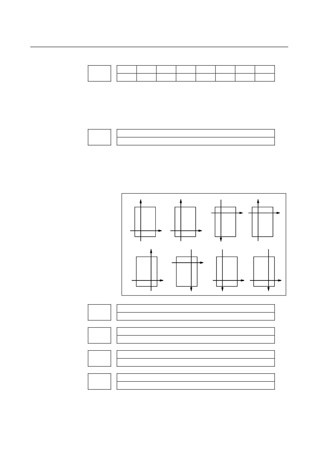
0 to 7
This parameter specifies the drawing coordinate system for the
graphic function.
The following show the relationship between the set values and the
drawing coordinate systems.
Setting value = 0
Setting value = 1
Setting value = 2 Setting value = 3
Z
X
Z
Z
X
X
Z
X
Setting value = 4
Setting value = 5
Setting value = 6 Setting value = 7
X
Z
Z
X
Z
X
Z
X
6511
Right margin in solid drawing
6512
Left margin in solid drawing
6513
Upper margin in solid drawing
6514
Lower margin in solid drawing
[Data type] Word
[Unit of data] Dot
- 307 -
4.DESCRIPTION OF PARAMETERS
B-64120EN/01
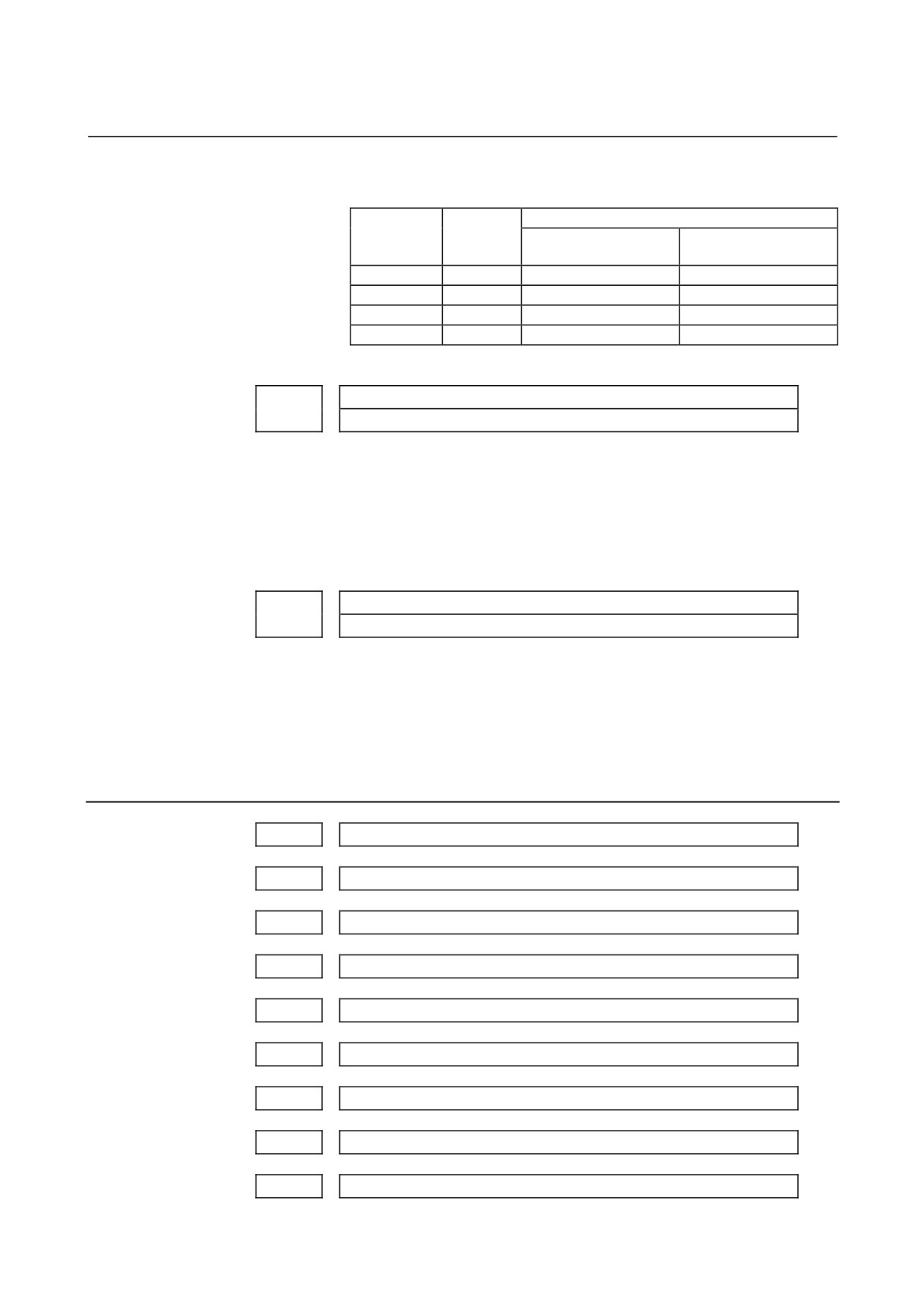
These parameters set the machining profile drawing position in
margins. The unit is a dot.
Standard set value
Parameter
Margin
No.
area
DPO = 0
DPO = 1
6511
Right
0
200
6512
Left
0
0
6513
Upper
25
25
6514
Lower
0
0
DPO is set in bit 5 (DPO) of parameter No. 6500.
6515
Change in cross-section position in tri-plane drawing
[Data type]
Byte
[Unit of data]
Dot
[Valid data range]
0 to 10
This parameter sets the change in the cross-section position when a
soft key is continuously pressed in tri-plane drawing. When zero is
specified, it is set to 1.
C-axis number for dynamic graphic display
6520
[Data type]
Byte
[Valid data range]
0, 1 to number of controlled axes
This parameter sets a C-axis number for dynamic graphic display.
When 0 or a value greater than the number of controlled axes is
specified with this parameter, the third axis is assumed.
4.34.2
Parameters of Graphic Color
6561
Standard color data for graphic color number 1
6562
Standard color data for graphic color number 2
6563
Standard color data for graphic color number 3
6564
Standard color data for graphic color number 4
6565
Standard color data for graphic color number 5
6566
Standard color data for graphic color number 6
6567
Standard color data for graphic color number 7
6568
Standard color data for graphic color number 8
6569
Standard color data for graphic color number 9
- 308 -

B-64120EN/01
4.DESCRIPTION OF PARAMETERS
6570
Standard color data for graphic color number 10
6571
Standard color data for graphic color number 11
6572
Standard color data for graphic color number 12
6573
Standard color data for graphic color number 13
6574
Standard color data for graphic color number 14
6575
Standard color data for graphic color number 15
6581
Standard color data for character color number 1
6582
Standard color data for character color number 2
6583
Standard color data for character color number 3
6584
Standard color data for character color number 4
6585
Standard color data for character color number 5
6586
Standard color data for character color number 6
6587
Standard color data for character color number 7
6588
Standard color data for character color number 8
6589
Standard color data for character color number 9
6590
Standard color data for character color number 10
6591
Standard color data for character color number 11
6592
Standard color data for character color number 12
6593
Standard color data for character color number 13
6594
Standard color data for character color number 14
6595
Standard color data for character color number 15
[Data type]
2-word
[Unit of data]
rr gg bb: 6-digit number (rr: Red gg: Green bb: Blue)
When a number of less than six digits is set, the system assumes that 0
has been specified for the unspecified higher digit(s).
- 309 -
4.DESCRIPTION OF PARAMETERS
B-64120EN/01
[Valid data range] Data of each color: 00 to 15 (same value as the tone level data on the
color setting screen)
When a value of more than 16 is set, the system assumes that 15 has
been specified.
Example:
Set 10203 in this parameter when the color tone levels are as
follows:
Red: 1 Green: 2 Blue: 3
NOTE
To set the color of the VGA display, use the color
setting screen. Note that the color changes when
the settings of parameters No.6561 through
No.6595 are modified.
- 310 -
B-64120EN/01
4.DESCRIPTION OF PARAMETERS
4.35
PARAMETERS OF DISPLAYING OPERATION TIME AND
NUMBER OF PARTS
#7
#6
#5
#4
#3
#2
#1
#0
6700
PRT
PCM
[Data type]
Bit
PCM
M code that counts the total number of machined parts and the number
of machined parts
0 : M02, or M30, or an M code specified by parameter No.6710
1 : Only M code specified by parameter No.6710
PRT
Upon reset, signal PRTSF <F062#7>, which indicates that a required
number of parts has been reached, is:
0 : Turned off.
1 : Not turned off.
M code that counts the total number of machined parts and the number of
6710
machined parts
[Data type]
2-word
[Valid data range]
0 to 255 except 98 and 99
The total number of machined parts and the number of machined
parts are counted (+1) when the M code set is executed.
NOTE
Set value 0 is invalid (the number of parts is not
counted for M00). Data 98 and 99 cannot be set.
6711
Number of machined parts
The following parameter can be set at "Setting screen".
[Data type]
2-word
[Unit of data]
One piece
[Valid data range]
0 to 99999999
The number of machined parts is counted (+1) together with the total
number of machined parts when the M02, M30, or a M code specified
by parameter No.6710 is executed.
NOTE
The number of parts is not counted for M02, M03,
when bit 0 (PCM) of parameter No. 6700 is set to
1.
- 311 -

4.DESCRIPTION OF PARAMETERS
B-64120EN/01
6712
Total number of machined parts
The following parameter can be set at "Setting screen".
[Data type]
2-word
[Unit of data]
One piece
[Valid data range]
0 to 99999999
This parameter sets the total number of machined parts.
The total number of machined parts is counted (+1) when M02, M30,
or an M code specified by parameter No.6710 is executed.
NOTE
The number of parts is not counted for M02, M03,
when bit 0 (PCM) of parameter No. 6700 is set to
1.
6713
Number of required parts
The following parameter can be set at "Setting screen".
[Data type]
Word
[Unit of data]
One piece
[Valid data range]
0 to 9999
This parameter sets the number of required machined parts.
Required parts finish signal PRTSF <F062#7> is output to PMC when
the number of machined parts reaches the number of required parts.
The number of parts is regarded as infinity when the number of
required parts is zero. The PRTSF <F062#7> signal is then not output.
6750
Integrated value of power-on period
The following parameter can be set at "Setting screen".
[Data type]
2-word
[Unit of data]
min
[Valid data range]
0 to 99999999
This parameter displays the integrated value of power-on period.
6751
Operation time (integrated value of time during automatic operation) I
The following parameter can be set at "Setting screen".
[Data type]
2-word
[Unit of data]
msec
[Valid data range]
0 to 60000
- 312 -
B-64120EN/01
4.DESCRIPTION OF PARAMETERS
6752
Operation time (integrated value of time during automatic operation) II
The following parameter can be set at "Setting screen".
[Data type]
2-word
[Unit of data]
min
[Valid data range]
0 to 99999999
This parameter displays the integrated value of time during automatic
operation (neither stop nor hold time included).
The actual time accumulated during operation is the sum of this
parameter No. 6751 and parameter No. 6752.
6753
Integrated value of cutting time I
The following parameter can be set at "Setting screen".
[Data type]
2-word
[Unit of data]
msec
[Valid data range]
1 to 60000
6754
Integrated value of cutting time II
The following parameter can be set at "Setting screen".
[Data type]
2-word
[Unit of data]
min
[Valid data range]
0 to 99999999
This parameter displays the integrated value of a cutting time that is
performed in cutting feed such as linear interpolation
(G01) and
circular interpolation (G02 or G03).
The actual time accumulated during cutting is the sum of this
parameter No. 6753 and parameter No. 6754.
Integrated value of general-purpose integrating meter drive signal (TMRON)
6755
ON time I
The following parameter can be set at "Setting screen".
[Data type]
2-word
[Unit of data]
msec
[Valid data range]
0 to 60000
Integrated value of general-purpose integrating meter drive signal (TMRON)
6756
ON time II
The following parameter can be set at "Setting screen".
[Data type]
2-word
[Unit of data]
min
[Valid data range]
0 to 99999999
This parameter displays the integrated value of a time while input
signal TMRON <G053#0> from PMC is on.
The actual integrated time is the sum of this parameter No. 6755 and
parameter No. 6756.
6757
Operation time (integrated value of one automatic operation time) I
- 313 -
4.DESCRIPTION OF PARAMETERS
B-64120EN/01
The following parameter can be set at "Setting screen".
[Data type]
2-word
[Unit of data] msec
[Valid data range]
0 to 60000
6758
Operation time (integrated value of one automatic operation time) II
The following parameter can be set at "Setting screen".
[Data type]
2-word
[Unit of data] min
[Valid data range]
0 to 99999999
This parameter displays the one automatic operation drive time
(neither stop nor hold state included). The actual time accumulated
during operating is the sum of this parameter No. 6757 and parameter
No. 6758. The operation time is automatically preset to 0 during the
power-on sequence and the cycle start from the reset state.
- 314 -
B-64120EN/01
4.DESCRIPTION OF PARAMETERS
4.36
PARAMETERS OF TOOL LIFE MANAGEMENT
#7
#6
#5
#4
#3
#2
#1
#0
SNG
GRS
SIG
LTM
GS2
GS1
6800
M6T
IGI
SNG
GRS
SIG
LTM
GS2
GS1
[Data type]
Bit
GS1, GS2
This parameter sets the combination of the number of tool life groups
which can be entered, and the number of tools which can be entered
per group as shown in the table below.
M series
T series
GS2
GS1
Group count
Tool count
Group count
Tool count
0
0
1 to 16
1 to 16
1 to 16
1 to 16
0
1
1 to 32
1 to 8
1 to 32
1 to 8
1
0
1 to 64
1 to 4
1 to 64
1 to 4
1
1
1 to 128
1 to 2
1 to 16
1 to 16
LTM
Tool life
0 : Specified by the number of times
1 : Specified by time
SIG
Group number is
0 : Not input using the tool group signal during tool skip
(The
current group is specified.)
1 : Input using the tool group signal during tool skip
GRS
Tool exchange reset signal TLRST<G048#7>
0 : Clears only the execution data of a specified group
1 : Clears the execution data of all entered groups
SNG
Input of the tool skip signal TLSKP <G048#5> when a tool that is not
considered tool life management is selected.
0 : Skips the tool of the group used last or of the specified group
(using SIG , #3 of parameter No.6800).
1 : Ignores a tool skip signal
IGI
Tool back number
0 : Not ignored
1 : Ignored
M6T
T code in the same block as M06
0 : Judged as a back number
1 : Judged as a next tool group command
#7
#6
#5
#4
#3
#2
#1
#0
EXG
E1S
TSM
6801
M6E
E1S
E1S
EMD
LFV
[Data type]
Bit
TSM
When a tool takes several tool numbers, life is counted in tool life
management:
0 : For each of the same tool numbers.
1 : For each tool.
- 315 -

4.DESCRIPTION OF PARAMETERS
B-64120EN/01
LFV
The life count override in the extended tool life management function
is:
0 : Disabled.
1 : Enabled.
EMD
An asterisk (*) indicating that a tool has been expired is
displayed,
0 : When the next tool is selected
1 : When the tool life is expired
E1S
When the life of a tool is measured in time-based units:
0 : The life is counted every four seconds.
1 : The life is counted every second. (The maximum life is 1075
(minutes).)
NOTE
This parameter is valid when bit 2 (LTM) of
parameter No.6800 is set to 1.
EXT
Specifies whether the extended tool life management function
(M
series) is used.
0 : Not used
1 : Used
EXG
Tool life management data registration by G10 (T series) is:
0 : Performed after the data for all tool groups has been cleared.
1 : Performed by adding/changing or deleting the data for a
specified group.
NOTE
When EXG = 1, address P in the block including
G10 can be used to specify whether data is to be
added/changed or deleted (P1: add/change, P2:
delete). When P is not specified, the data for all
tool groups is cleared before the tool life
management data is registered.
M6E
When a T code is specified in the same block as M06
0 : The T code is processed as a return number or as a group number
selected next. Either is set by parameter M6T (No.6800#7).
1 : The tool group life is counted immediately.
#7
#6
#5
#4
#3
#2
#1
#0
T99
6802
RMT
TSK
E17
TCO
T99
[Data type]
Bit
T99
If a tool group whose life has expired is found to exist when M99 is
executed in the main program:
0 : The tool change signal is not output.
1 : The tool change signal is output.
TCO
When function code 171 or 172 (tool life management data write) of
the PMC window function is specified, tool data of a tool in the
currently selected group that is currently not in use:
- 316 -
B-64120EN/01
4.DESCRIPTION OF PARAMETERS
0 : Cannot be cleared.
1 : Can be cleared.
E17
When function code 171 or 172 (tool life management data write) of
the PMC window function is specified to clear tool life management
data of the tool currently in use in the currently selected group:
0 : The tool data is not cleared and operation terminates normally.
1 : The tool data is not cleared and completion code 13 is output.
TSK
When the life is specified by time and the last tool in a group is
skipped in tool life management:
0 : The count for the last tool indicates the life value.
1 : The count for the last tool is not changed.
RMT
Specifies when to turn off the tool life arrival signal TLCHB, as
follows:
0 : The actual remaining life is longer than that specified in a
parameter ("less than" type).
1 : The actual remaining life is not equal to that specified in a
parameter ("equal" type).
#7
#6
#5
#4
#3
#2
#1
#0
LFE
LGR
6803
LFE
NOTE
After this parameter has been set, the power must
be turned off then on again for the setting to
become effective.
[Data type]
Bit
LGR
When the tool life management function is used, a tool life type is:
0 : Chosen based on the LTM parameter
(bit
2 of parameter
No.6800) for all groups.
1 : Set to either count or duration on a group-by-group basis.
When LGR is set to 1, the specification of address Q is added to the
G10 (tool life management data setting) command format. As shown
in the example below, specify the tool life of each group as either a
count (Q1) or a duration (Q2). If address Q is omitted for a group, the
specification of the LTM parameter (bit 2 of parameter No.6800)
applies to the group.
Example:
When the LTM parameter (bit 2 of parameter No.6800) is set to 0
G10 L3 ;
P1 L10 Q1 ; (Q1: The life of group 1 is specified as a count.)
:
P2 L20 Q2 ; (Q2: The life of group 2 is specified as a duration.)
:
P3 L20 ;
(Omission of Q: The life of group 3 is specified as a count.)
:
G11 ;
M30 ;
- 317 -

4.DESCRIPTION OF PARAMETERS
B-64120EN/01
%
LFE
When a tool life is specified by count:
0 : A count value from 0 to 9999 can be specified.
1 : A count value from 0 to 65535 can be specified.
#7
#6
#5
#4
#3
#2
#1
#0
TC1
6804
ETE
TC1
E10
[Data type]
Bit
E10
When the tool life is specified by time:
0 : The tool life is counted at intervals of 4 seconds.
1 : The tool life is counted at intervals of 10 seconds.
NOTE
This parameter is valid when bit 2 (LTM) of
parameter No. 6800 is set to 1.
TC1
During automatic operation, preset of the tool life counter is:
0 : Disabled.
1 : Enabled.
ETE
In extended tool life management, as the mark indicating that the life
of the last tool in a group has expired:
0 : "@" is also used.
1 : "*" is used.
6810
Tool life management ignored number
[Data type]
Word
[Valid data range]
0 to 9999
This parameter sets the tool life management ignored number.
When the set value is subtracted from a T code, a remainder is used as
the tool group number of tool life management when a value
exceeding the set value is specified in the T code.
- 318 -

B-64120EN/01
4.DESCRIPTION OF PARAMETERS
Tool life count restart M code
6811
[Data type]
2-word
[Valid data range]
0 to 255 (not including 01, 02, 30, 98, and 99)
When zero is specified, it is ignored.
When the life is specified by the number of times, the tool exchange
signal is output when a tool life count restart M code is specified if
tool life of at least one tool group is expired. A tool in life is selected
in the specified group when a T code command (tool group command)
is specified after the tool life count restart M code is specified. A tool
life counter is then incremented by one.
When the life is specified by time, a tool in life is selected in the
specified group when a T code command (tool group command) is
specified after the tool life count restart M code is specified.
6844
Remaining tool life (use count)
[Data type]
Word
[Unit of data]
Count
[Valid data range]
0 to 9999
This parameter sets a remaining tool life (use count) used to output the
tool life arrival notice signal TLCHB <F064#3> when the tool life is
specified as a use count.
NOTE
1 When the remaining life (use count) of a selected
tool reaches the value specified with this
parameter, tool life arrival notice signal TLCHB is
output to the PMC.
2 If a value greater than the life of a tool is specified
with this parameter, the tool life arrival notice signal
TLCHB is not output.
6845
Remaining tool life (use duration)
[Data type]
2-word
[Unit of data]
min
[Valid data range]
0 to 4300
This parameter sets the remaining tool life (use duration), used to
output the tool life arrival notice signal TLCHB <F064#3> when the
tool life is specified as a use duration.
- 319 -

4.DESCRIPTION OF PARAMETERS
B-64120EN/01
NOTE
1 When the remaining life (use duration) of a
selected tool reaches the value specified in this
parameter, tool life arrival notice signal TLCHB is
output to the PMC. The tool life management
function allows the user to specify a tool life either
as a use duration or use count for each tool group.
For a group whose life is specified as a use count,
parameter No.6844 is used. For a group whose life
is specified as a use time, this parameter is used.
2 If a value greater than the life of a tool is specified
with parameter No.6845, the tool life arrival notice
signal TLCHB is not output.
6846
Number of remaining tools in a group
[Data type]
Byte
[Valid data range]
0 to 127
This parameter sets the number of remaining tools in a group.
If the number of remaining tools in the currently used group is equal
to or smaller than the number set in this parameter, signal TLAL
<F154#0> is output. If this parameter is set to 0, the signal is not
output.
- 320 -

B-64120EN/01
4.DESCRIPTION OF PARAMETERS
4.37
PARAMETERS OF POSITION SWITCH FUNCTIONS
#7
#6
#5
#4
#3
#2
#1
#0
PCM
EPS
IGP
6901
PSF
PCM
EPS
IGP
[Data type]
Bit
IGP
During follow-up for the absolute position detector, position switch
signals are:
0 : Output
1 : Not output
EPS
The number of position switches is:
0 : Up to 10.
1 : Up to 16.
PCM
Position switch signals are output:
0 : Without considering acceleration/deceleration and servo delay.
1 : With considering acceleration/deceleration and servo delay.
PSF
In advanced preview control mode, AI advanced preview control
mode, or AI contour control mode, position switches are:
0 : Not used.
1 : Used.
NOTE
The position switch signals are output considering
acceleration/deceleration after interpolation and
servo delay. Acceleration/deceleration after
interpolation and servo delay are considered even
for position switch signal output in a mode other
than advanced preview control mode, AI advanced
preview control mode, and AI contour control
mode. When this parameter is set to 1, however,
signals are output from the position switches at
different times from the specified ones.
- 321 -