FANUC Series 0i-MODEL C, Series 0i Mate-MODEL C. PARAMETER MANUAL (B-64120EN/01) - page 10

4.DESCRIPTION OF PARAMETERS
B-64120EN/01
Time constant for the spindle and tapping axis in extraction operation
5271
(first-stage gear)
Time constant for the spindle and tapping axis in extraction operation
5272
(second-stage gear)
Time constant for the spindle and tapping axis in extraction operation
5273
(third-stage gear)
Time constant for the spindle and tapping axis in extraction operation
5274
(fourth-stage gear)
[Data type] Word
[Unit of data] ms
[Valid data range]
0 to 4000
Each of these parameters is used to set a linear
acceleration/deceleration time constant for the spindle of each gear
and tapping axis in extraction operation during rigid tapping.
NOTE
1 These parameters are enabled when the TDR
parameter (bit 2 of parameter No.5201) is set to 1.
2 When rigid tapping is performed using the second
spindle
• When the SPR parameter (bit 1 of parameter
No.5204) is set to 0, the settings of parameters
No.5271 and No.5272 are applied to the second
spindle, as well as to the first spindle.
• When the SPR parameter (bit 1 of parameter
No.5204) is set to 1, the settings of parameters
No.5335 and No.5336 are applied to the second
spindle.
- 262 -

B-64120EN/01
4.DESCRIPTION OF PARAMETERS
Position control loop gain for the spindle and tapping axis in rigid tapping
5280
(common to all gears)
Position control loop gain for the spindle and tapping axis in rigid tapping
5281
(first-stage gear)
Position control loop gain for the spindle and tapping axis in rigid tapping
5282
(second-stage gear)
Position control loop gain for the spindle and tapping axis in rigid tapping
5283
(third-stage gear)
Position control loop gain for the spindle and tapping axis in rigid tapping
(fourth-stage gear)
5284
NOTE
Once these parameters have been set, the power
must be turned off then back on for the settings to
become effective.
[Data type]
Word
[Unit of data]
0.01 s-1
[Valid data range]
1 to 9999
Each of these parameters is used to set a position control loop gain for
the spindle and tapping axis in rigid tapping. These parameters
significantly affect the precision of threading. Conduct cutting tests,
and make adjustments to obtain an optimum value.
When performing threading with an analog spindle, also adjust the
loop gain multipliers (parameter Nos. 5291 to 5294).
NOTE
1 To use a varied loop gain on a gear-by-gear basis,
set parameter No.5280 to 0, and set a loop gain for
each gear in parameters No.5281 through
No.5284. The specification of a loop gain on a
gear-by-gear basis is disabled if parameter
No.5280 is set to a value other than 0. In such a
case, the value set in parameter No.5280 is used
as a loop gain that is common to all the gears.
2 When rigid tapping is performed using the second
spindle
• When the SPR parameter (bit 1 of parameter
No.5204) is set to 0, the setting of parameter
No.5280 or the settings of parameters No.5281
and No.5282 are applied to the second spindle,
as well as to the first spindle.
• When the SPR parameter (bit 1 of parameter
No.5204) is set to 1, the settings of parameters
No.5341 through No.5343 are applied to the
second spindle.
- 263 -
4.DESCRIPTION OF PARAMETERS
B-64120EN/01
5291
Spindle loop gain multiplier in the rigid tapping mode (for gear 1)
5292
Spindle loop gain multiplier in the rigid tapping mode (for gear 2)
5293
Spindle loop gain multiplier in the rigid tapping mode (for gear 3)
Spindle loop gain multioplier in the rigid tapping mode (for gear4)
5294
[Data type]
Word type
[Valid data range]
0 to 32767
Set the spindle loop gain multipliers for gears 1 to 4 in the rigid
tapping mode. The thread precision depends on the multipliers.
Conduct cutting tests, and make fine adjustments to obtain an
optimum value.
NOTE
These parameters are used for analog spindles.
Loop gain multiplier = 2048 × E/L × α × 1000
where;
E : Voltage in the velocity command at 1000 min-1
L : Rotation angle of the spindle per one rotation of the spindle
motor
α : Unit used for the detection
Examples
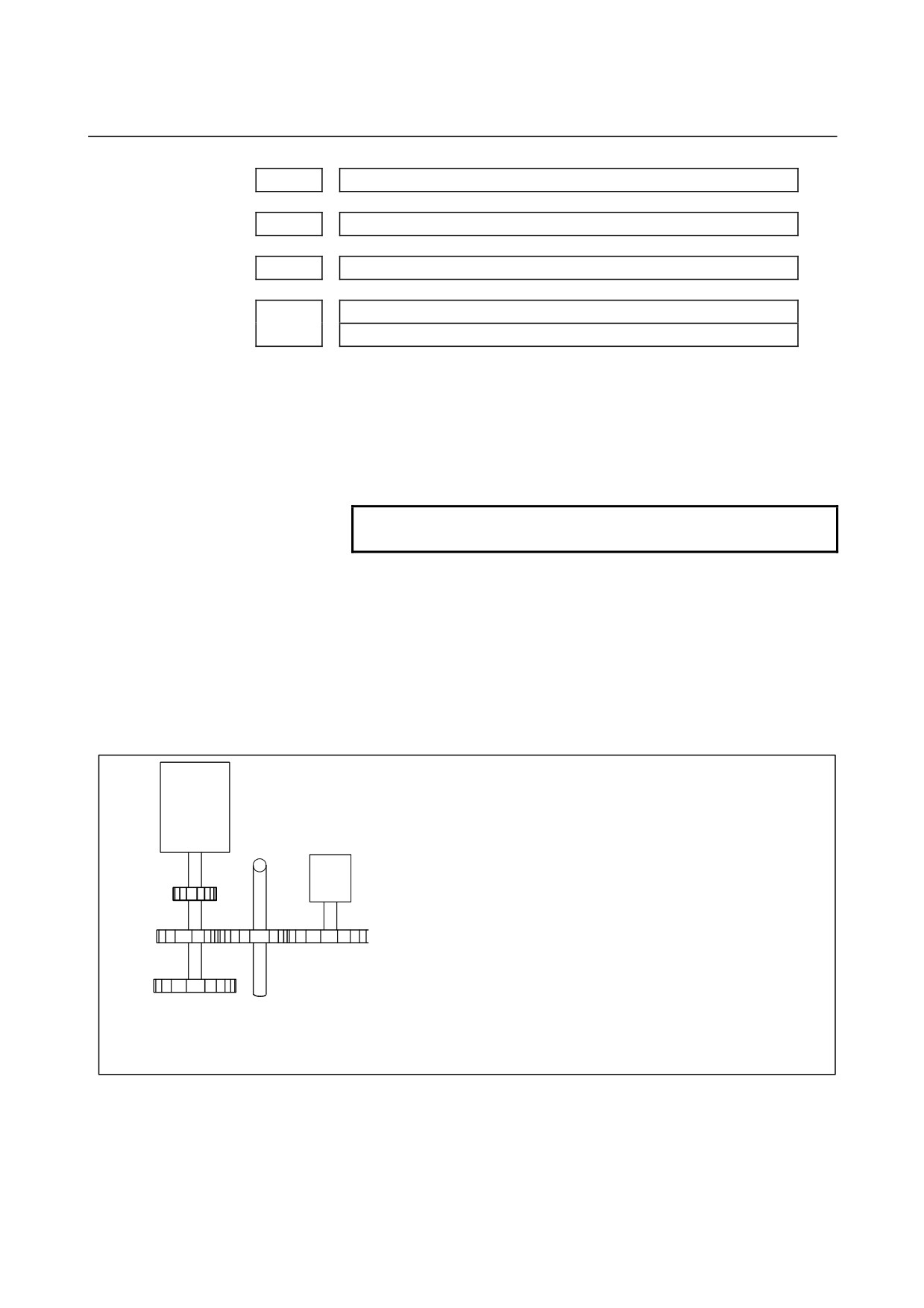
When the spindle motor, spindle, and position coder are connected as shown
left, let the variables be as follows:
Spindle
E = 1.667 (V)
(A motor speed of 6000 min-1 corresponds to 10 V.)
Motor
L = 360°
(One rotation of the spindle corresponds to one rotation of the
Position
spindle motor.)
Spindle
coder
a
= La/4096
= 720°/4096
P.C
= 0.17578
La = 720°
(= 360° × 2. One rotation of the position coder corresponds to two
rotations of the spindle.)
4096 =
The number of detected pulses per rotation of the position coder
Gear ratio between the spindle and the position coder
1:1
0.08789 degrees
1:2
0.17578 degrees
1:4
0.35156 degrees
1:8
0.70313 degrees
1 : 1 : 2
According to above ratio the loop gain multiplier is calculated as
2048 × 1.667/360 × 0.17578 × 1000 = 1667
When the position coder which is built in a spindle motor sends 512 pulses
per rotation, the unit used for the detection, a, is La/2048.
Fig.4.23 (b) Connection among the spindle motor, spindle, and position coder
- 264 -

B-64120EN/01
4.DESCRIPTION OF PARAMETERS
5300
Tapping axis in-position width in rigid tapping
5301
Spindle in-position width in rigid tapping
[Data type]
Word
[Unit of data]
Detection unit
[Valid data range]
0 to 32767
These parameters are used to set tapping axis and spindle in-position
widths in rigid tapping.
NOTE
1 If an excessively large value is specified, the
threading precision will deteriorate.
2 When rigid tapping is performed using the second
spindle
• When the SPR parameter (bit 1 of parameter
No.5204) is set to 0, the settings of parameter
No.5300 and No.5301 are applied to the second
spindle, as well as to the first spindle.
• When the SPR parameter (bit 1 of parameter
No.5204) is set to 1, the settings of parameters
No.5302 and No.5303 are applied to the second
spindle.
5302
Tapping axis in-position width in rigid tapping using the second spindle
5303
Spindle in-position width in rigid tapping using the second spindle
[Data type]
Word
[Unit of data]
Detection unit
[Valid data range]
0 to 32767
These parameters are used to set spindle and tapping axis in-position
widths in rigid tapping using the second spindle.
NOTE
These parameters are enabled when the SPR
parameter (bit 1 of parameter No.5204) is set to 1.
5308
In-position width at point R in rigid tapping (tapping axis)
[Data type]
Word
[Unit of data]
Detection unit
[Valid data range]
0 to 32767
This parameter is used to set the tapping axis in-position width at
point R in rigid tapping.
- 265 -

4.DESCRIPTION OF PARAMETERS
B-64120EN/01
Positional deviation limit imposed during tapping axis movement in rigid
5310
tapping
[Data type]
Word
[Unit of data]
Detection unit
[Valid data range]
1 to 32767
This parameter is used to set a positional deviation limit during
tapping axis movement in rigid tapping. A value that falls outside the
valid data range, described above, can be specified in parameter
No.5314.
NOTE
1 When a high-resolution detector is used, the unit
must be multiplied by 10.
2 When rigid tapping is performed using the second
spindle
• When the SPR parameter (bit 1 of parameter
No.5204) is set to 0, the setting of parameter
No.5310 (or No.5314) is applied to the second
spindle, as well as to the first spindle.
• When the SPR parameter (bit 1 of parameter
No.5204) is set to 1, the setting of parameter
No.5350 is applied to the second spindle,
respectively.
Limit value of spindle positioning deviation during movement in rigid
5311
tapping.
[Data type]
Word
[Unit of data]
Detection unit
[Valid data range]
1 to 32767
This parameter sets the limit value of a spindle positioning deviation
during movement in rigid tapping.
S × 360 × 100 × 1.5
Limit value =
60 × G × α
where
S : Maximum spindle speed in rigid tapping
(Setting value of parameter Nos. 5241 and greater)
G : Loop gain of rigid tapping axis
(Setting value of parameter Nos. 5280 and greater)
α : Detection unit
- 266 -
B-64120EN/01
4.DESCRIPTION OF PARAMETERS
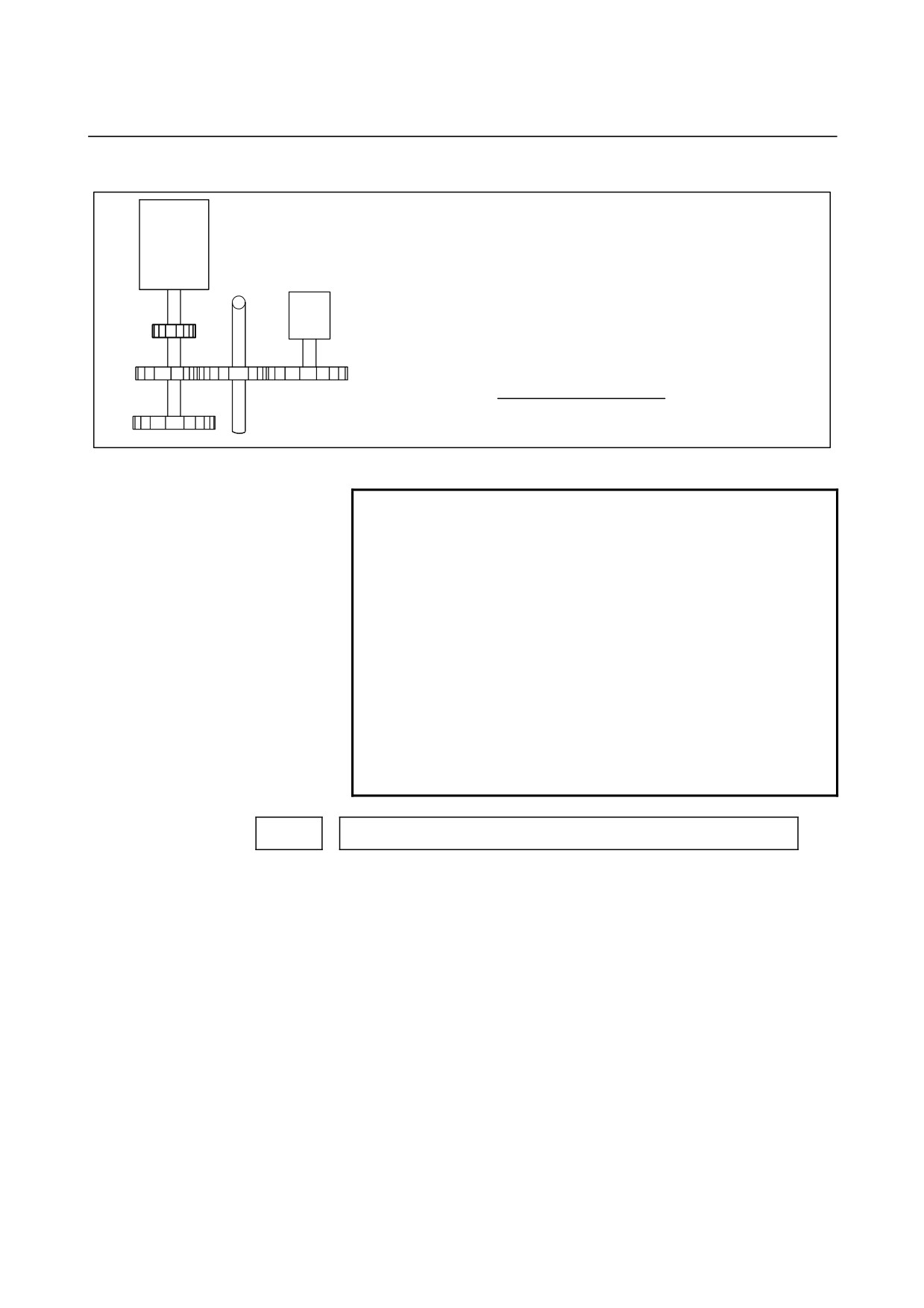
Calculation example
S
= 3600
Spindle
G
= 3000
Motor
L
= 360 degrees (One spindle rotation per spindle motor rotation)
Position
a
= La/4096
Spindle
coder
= 720 degrees/4096
= 0.17578 degrees
P.C
La = 720 degrees
(One position coder rotation requires two spindle rotations (= 360
degrees × 2)).
4096 = Detection pulse per position coder rotation
3600 × 360 × 100 × 1.5
Setting value =
60 × 3000 × 0.17578
= 6144
1 : 1 : 2
Fig.4.23 (c) Connection Among Spindle Motor, Spindle and Position Coder
NOTE
1 The detection unit is a = La/2048 when the position
coder built-in spindle motor uses a position coder
of 512 pulses per revolution.
2 When rigid tapping is performed using the second
spindle
• When the SPR parameter (bit 1 of parameter
No.5204) is set to 0, the setting of parameter
No.5311 is applied to the second spindle, as
well as to the first spindle.
• When the SPR parameter (bit 1 of parameter
No.5204) is set to 1, the setting of parameter
No.5351 is applied to the second spindle,
respectively.
Positional deviation limit imposed while the tapping axis is stopped in rigid
5312
tapping
[Data type] Word
[Unit of data] Detection unit
[Valid data range]
1 to 32767
This parameter is used to set a positional deviation limit imposed
while the tapping axis is stopped in rigid tapping.
- 267 -

4.DESCRIPTION OF PARAMETERS
B-64120EN/01
NOTE
When rigid tapping is performed using the second
spindle
• When the SPR parameter (bit 1 of parameter
No.5204) is set to 0, the setting of parameter
No.5312 is applied to the second spindle, as
well as to the first spindle.
• When the SPR parameter (bit 1 of parameter
No.5204) is set to 1, the setting of parameter
No.5352 is applied to the second spindle,
respectively.
Positional deviation limit imposed while the spindle is stopped in rigid
5313
tapping
[Data type]
Word
[Unit of data]
Detection unit
[Valid data range]
1 to 32767
This parameter is used to set a positional deviation limit imposed
while the spindle is stopped in rigid tapping.
NOTE
When rigid tapping is performed using the second
spindle
• When the SPR parameter (bit 1 of parameter
No.5204) is set to 0, the setting of parameter
No.5313 is applied to the second spindle, as
well as to the first spindle.
• When the SPR parameter (bit 1 of parameter
No.5204) is set to 1, the setting of parameter
No.5353 is applied to the second spindle,
respectively.
Positional deviation limit imposed during tapping axis movement in rigid
5314
tapping
[Data type]
2-word
[Unit of data]
Detection unit
[Valid data range]
0 to 99999999
Usually, parameter No.5310 is used to set a positional deviation limit
imposed during tapping axis movement in rigid tapping. However,
parameter No.5314 can be used to set a value greater than the valid
data range of parameter No.5310 because of the resolution of the
detector being used.
- 268 -

B-64120EN/01
4.DESCRIPTION OF PARAMETERS
NOTE
1
When parameter No.5314 is set to 0, the setting of
parameter No.5310 is used. When parameter
No.5314 is set to a value other than 0, parameter
No.5310 is disabled; in this case, the setting of
parameter No.5314 is used.
2
When rigid tapping is performed using the second
spindle
• When the SPR parameter (bit 1 of parameter
No.5204) is set to 0, the setting of parameter
No.5314 (or No.5310) is applied to the second
spindle, as well as to the first spindle.
• When the SPR parameter (bit 1 of parameter
No.5204) is set to 1, the setting of parameter
No.5350 is applied to the second spindle,
respectively.
Spindle backlash in rigid tapping (first-stage gear)
5321
Spindle backlash in rigid tapping
Spindle backlash in rigid tapping (second-stage gear)
5322
Spindle backlash in rigid tapping (third-stage gear)
5323
Spindle backlash in rigid tapping (fourth-stage gear)
5324
Spindle backlash in rigid tapping using the second spindle (first-stage gear)
5325
Spindle backlash in rigid tapping using the second spindle (second-stage
gear)
5326
[Data type]
Byte
[Unit of data]
Detection unit
[Valid data range]
0 to 127
Each of these parameters is used to set a spindle backlash.
- 269 -
4.DESCRIPTION OF PARAMETERS
B-64120EN/01
NOTE
When rigid tapping is performed using the second
spindle
• When the SPR parameter (bit 1 of parameter
No.5204) is set to 1, the settings of parameters
No.5325 and No.5326 are applied to the second
spindle.
• When the SPR parameter (bit 1 of parameter
No.5204) is set to 0, the settings of parameters
No.5321 and No.5322 are applied to the second
spindle, as well as to the first spindle.
Time constant for the spindle and tapping axis in second spindle extraction
operation (first-stage gear)
5335
Time constant for the spindle and tapping axis in second spindle extraction
operation (second-stage gear)
5336
[Data type]
Word
[Unit of data]
ms
[Valid data range]
0 to 4000
Each of these parameters is used to set a linear
acceleration/deceleration time constant for the spindle and tapping
axis in extraction operation during rigid tapping on a gear-by-gear
basis.
NOTE
This parameter is enabled when both the TDR
parameter (bit 2 of parameter No.5201) and the
SPR parameter (bit 1 of parameter No.5204) are
set to 1.
- 270 -
B-64120EN/01
4.DESCRIPTION OF PARAMETERS
Position control loop gain for the spindle and tapping axis in rigid tapping
using the second spindle (common to all the gears)
5341
Position control loop gain for the spindle and tapping axis in rigid tapping
using the second spindle (first-stage gear)
5342
Position control loop gain for the spindle and tapping axis in rigid tapping
using the second spindle (second-stage gear)
5343
NOTE
After these parameters have been set, the power
must be turned off then back on for the settings to
become effective.
[Data type]
Word
[Unit of data]
0.01 s-1
[Valid data range]
1 to 9999
Each of these parameters is used to set a position control loop gain for
the spindle and tapping axis in rigid tapping using the second spindle.
NOTE
1 To use a varied loop gain on a gear-by-gear basis,
set parameter No.5341 to 0, and set a loop gain for
each gear in parameters No.5342 and No.5343.
2 This parameter is enabled when the SPR
parameter (bit 1 of parameter No.5204) is set to 1.
Positional deviation limit imposed during tapping axis movement in rigid
tapping using the second spindle
5350
[Data type]
2-word
[Unit of data]
Detection unit
[Valid data range]
1 to 99999999
This parameter sets a positional deviation limit imposed during
tapping axis movement in rigid tapping using the second spindle.
NOTE
This parameter is enabled when the SPR
parameter (bit 1 of parameter No.5204) is set to 1.
- 271 -
4.DESCRIPTION OF PARAMETERS
B-64120EN/01
Positional deviation limit imposed during spindle movement in rigid tapping
using the second spindle
5351
[Data type]
Word
[Unit of data]
Detection unit
[Valid data range]
1 to 32767
This parameter is used to set a positional deviation limit imposed
during spindle movement in rigid tapping using the second spindle.
NOTE
This parameter is enabled when the SPR
parameter (bit 1 of parameter No.5204) is set to 1.
Positional deviation limit imposed while the tapping axis is stopped in rigid
tapping using the second spindle
5352
[Data type]
Word
[Unit of data]
Detection unit
[Valid data range]
1 to 32767
This parameter is used to set a positional deviation limit imposed
while the tapping axis is stopped in rigid tapping using the second
spindle.
NOTE
This parameter is enabled when the SPR
parameter (bit 1 of parameter No.5204) is set to 1.
Positional deviation limit imposed while the spindle is stopped in rigid
tapping using the second spindle
5353
[Data type]
Word
[Unit of data]
Detection unit
[Valid data range]
1 to 32767
This parameter is used to set a positional deviation limit imposed
while the spindle is stopped in rigid tapping using the second spindle.
NOTE
This parameter is enabled when the SPR
parameter (bit 1 of parameter No.5204) is set to 1.
- 272 -
B-64120EN/01
4.DESCRIPTION OF PARAMETERS
5365
Bell-shaped acceleration/deceleration time constant for the first spindle in
rigid tapping (first-stage gear)
5366
Bell-shaped acceleration/deceleration time constant for the first spindle in
rigid tapping (second-stage gear)
5367
Bell-shaped acceleration/deceleration time constant for the first spindle in
rigid tapping (third-stage gear)
[Data type]
Word
[Unit of data]
msec
[Valid data range]
0 to 512
These parameters are used to set bell-shaped acceleration/deceleration
time constants for the first spindle in rigid tapping.
5369
Bell-shaped acceleration/deceleration time constant for the second spindle
in rigid tapping (first-stage gear)
5370
Bell-shaped acceleration/deceleration time constant for the second spindle
in rigid tapping (second-stage gear)
[Data type]
Word
[Unit of data]
msec
[Valid data range]
0 to 512
These parameters are used to set bell-shaped acceleration/deceleration
time constants for the second spindle in rigid tapping.
5381
Override value during rigid tapping return
[Data type]
Byte
[Unit of data]
1% or 10%
[Valid data range]
0 to 200
This parameter is used to set the override value during rigid tapping
return.
If the setting is 0, no override is applied.
NOTE
This parameter is valid when bit 4 (DOV) of
parameter No. 5200 is set to 1.
If bit 3 (OVU) of parameter No.5201 is set to 1,
10% is set as the units of data. Thus, an override
of up to 2000% can be applied during extraction.
- 273 -

4.DESCRIPTION OF PARAMETERS
B-64120EN/01
5382
Amount of return for rigid tapping return
[Data type]
2-word
[Unit of data] Input increments
[Valid data range]
0 to 99999999
During rigid tapping return, the tool can be pulled out, along the
tapping axis, going beyond the stored rigid tapping start position by
the amount specified with this parameter.
If the tool has already been retracted from rigid tapping, it will be
retracted further only by the distance specified in this parameter.
- 274 -
B-64120EN/01
4.DESCRIPTION OF PARAMETERS
4.24
PARAMETERS OF SCALING/COORDINATE ROTATION
#7
#6
#5
#4
#3
#2
#1
#0
5400
SCR
XSC
RCW
RIN
[Data type]
Bit
RIN
Coordinate rotation angle command (R)
0 : Specified by an absolute method
1 : Specified by G90 or G91
NOTE
For the G code system A (T series), this parameter
is invalid.
RCW
When a workpiece or local coordinate system command is issued in
coordinate system rotation mode:
0 : No alarm is issued.
1 : An alarm (P/S alarm No. 5302) is issued.
XSC
Scaling mirror image for each axis in scaling is:
0 : Disabled.
(The scaling magnification common to all axes is
specified with P.)
1 : Enabled. (The scaling magnification for each axis is specified
with I, J, and K.)
SCR
Scaling magnification unit
0 :
0.00001 times (1/100,000)
1 :
0.001 times
#7
#6
#5
#4
#3
#2
#1
#0
5401
SCLx
[Data type]
Bit axis
SCLx
Scaling
0 : Invalidated
1 : Validated
#7
#6
#5
#4
#3
#2
#1
#0
5402
S8D
[Data type]
Bit axis
S8D
The unit of scaling magnification is:
0 : Dependent on the setting of bit 7 (SCR) of parameter No. 5400.
1 :
0.0000001 (1/10,000,000).
- 275 -
4.DESCRIPTION OF PARAMETERS
B-64120EN/01
5410
Angular displacement used when no angular displacement is specified for
coordinate system rotation
The following parameter can be set at "Setting screen".
[Data type]
2-word
[Unit of data]
0.001 degrees
[Valid data range]
-360000 to 360000
This parameter sets the angular displacement for coordinate system
rotation. When the angular displacement for coordinate system
rotation is not specified with address R in the block where G68 is
specified, the setting of this parameter is used as the angular
displacement for coordinate system rotation.
5411
Magnification used when scaling magnification is not specified
The following parameter can be set at "Setting screen".
[Data type]
2-word
[Unit of data]
0.001,
0.00001, or
0.0000001 times (selected by bit
7 (SCR) of
parameter No. 5400) or bit 0 (S8D) of parameter No. 5402 (M series))
[Valid data range]
1 to 999999 (when 0.001 or 0.00001 times is selected)
1 to 99999999 (when 0.0000001 times is selected) (M series)
This parameter sets the scaling magnification. This setting value is
used when a scaling magnification (P) is not specified in the program.
NOTE
Parameter No.5421 becomes valid when scaling
for every axis is valid. (XSC, #6 of parameter
No.5400 is "1".)
5421
Scaling magnification for every axis
The following parameter can be set at "Setting screen".
[Data type]
2-word axis
[Unit of data]
0.001,
0.00001, or
0.0000001 times (selected by bit
7 (SCR) of
parameter No. 5400) or bit 0 (S8D) of parameter No. 5402 (M series))
[Valid data range]
-999999 to -1, 1 to 999999 (when 0.001 or 0.00001 times is selected)
-99999999 to -1, 1 to 99999999 (when 0.0000001 times is selected)
(M series)
This parameter sets the scaling magnification for every axis.
- 276 -
B-64120EN/01
4.DESCRIPTION OF PARAMETERS
4.25 PARAMETERS OF UNI-DIRECTIONAL POSITIONING
#7
#6
#5
#4
#3
#2
#1
#0
5431
PDI
MDL
[Data type] Bit
MDL Specifies whether the G code for single direction positioning (G60) is
included in one-shot G codes (00 group) or modal G codes (01 group)
0: One-shot G codes (00 group)
1: Modal G codes (01 group)
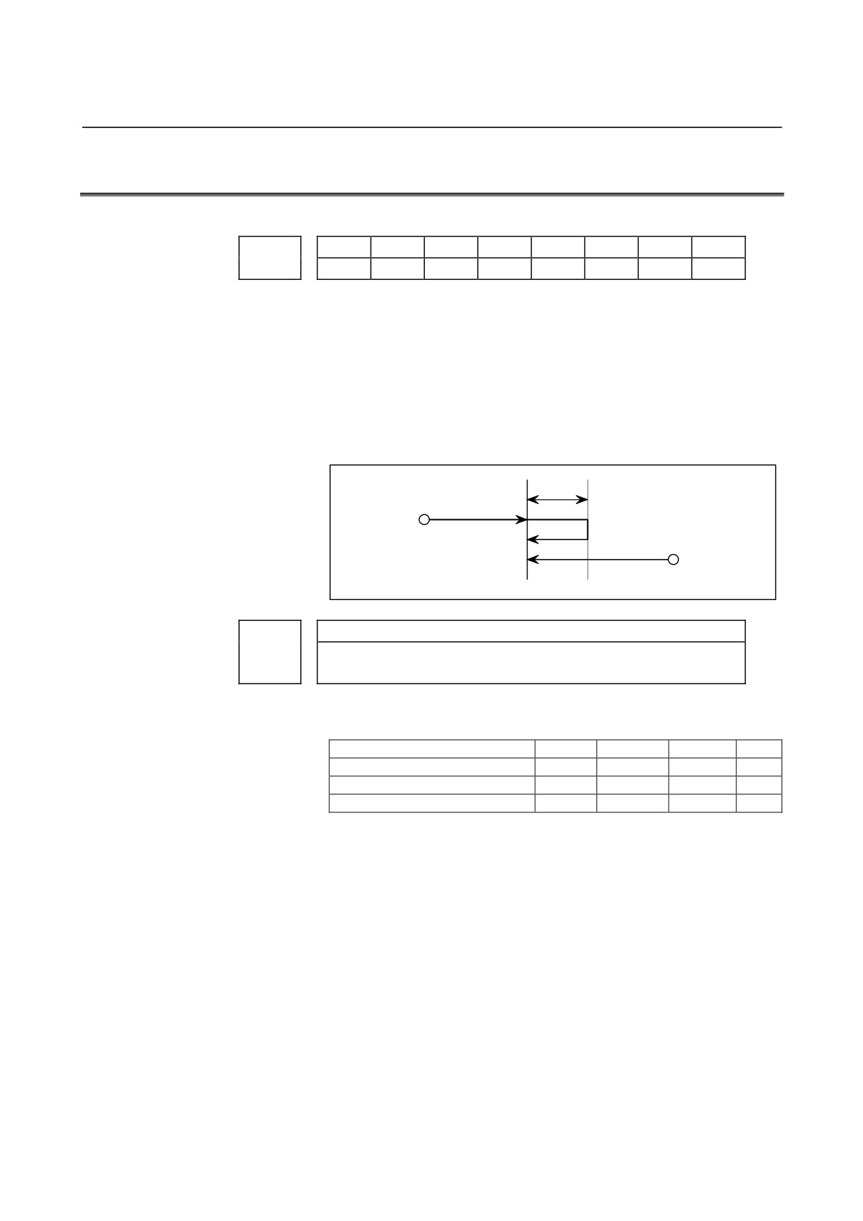
PDI When the tool is stopped before or after a specified end point with the
unidirectional positioning function:
0 : No in-position check is performed.
1 : An in-position check is performed.
Overrun
distance
Start point
Start point
End point
Stop after overrun
5440
Positioning direction and overrun distance in uni-directional positioning for
each axis
[Data type] Word axis
[Unit of data]
Input increment
IS-A
IS-B
IS-C
Unit
Millimeter machine
0.01
0.001
0.0001
mm
Inch machine
0.001
0.0001
0.00001
inch
Rotation axis
0.01
0.001
0.0001
deg
[Valid data range]
-16383 to +16383
This parameter sets the positioning direction and overrun distance in
uni-directional positioning
(G60) for each axis. The positioning
direction is specified using a setting data sign, and the overrun
distance using a value set here.
Overrun distance > 0: The positioning direction is positive (+).
Overrun distance < 0: The positioning direction is negative (-).
Overrun distance = 0: Uni-directional positioning is not performed.
- 277 -
4.DESCRIPTION OF PARAMETERS
B-64120EN/01
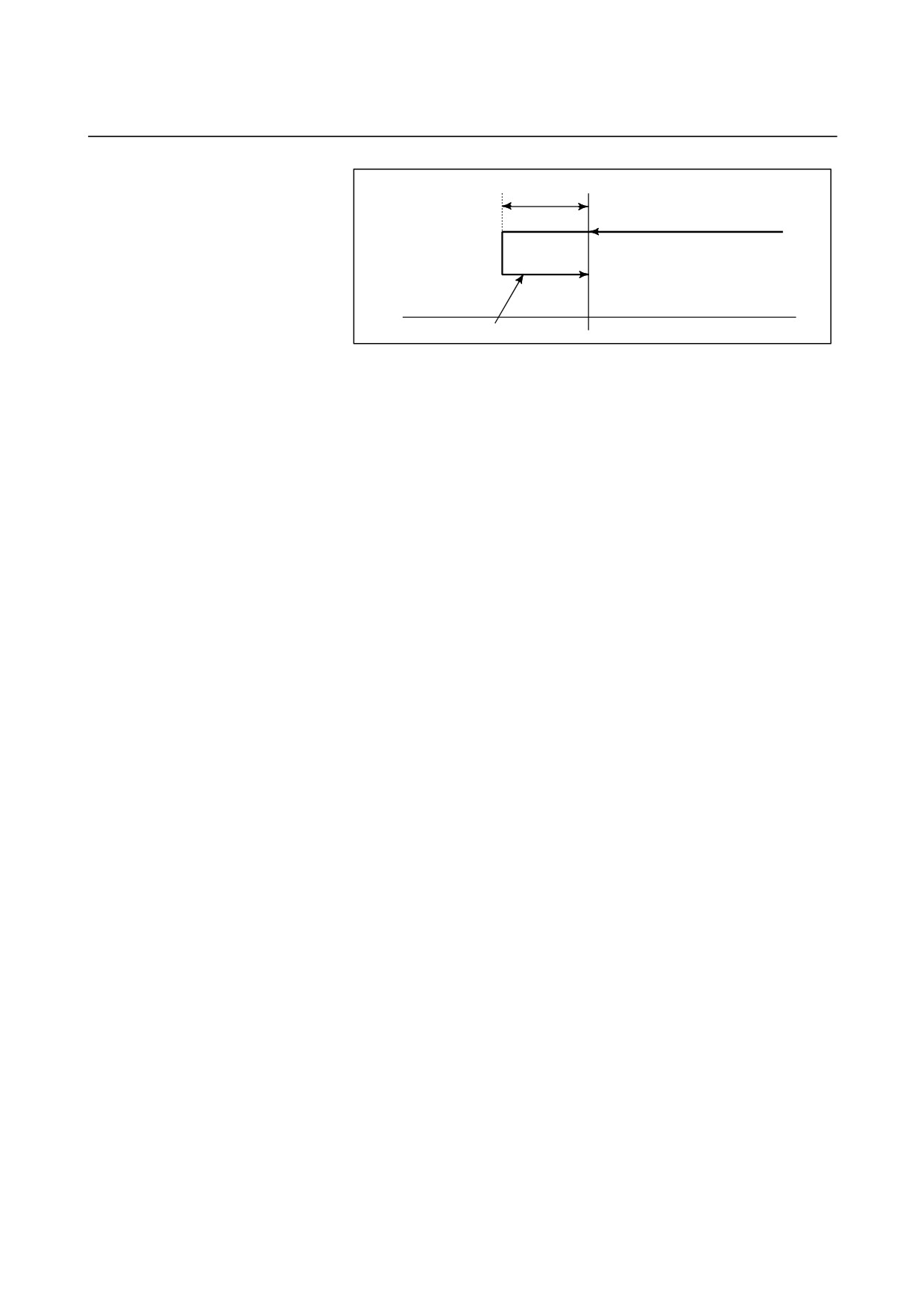
Overrun distance
-
+
Positioning direction (plus)
Fig.4.25 Positioning Direction and Overrun distance
- 278 -
B-64120EN/01
4.DESCRIPTION OF PARAMETERS
4.26
PARAMETERS OF POLAR COORDINATE
INTERPOLATION
#7
#6
#5
#4
#3
#2
#1
#0
AFC
5450
[Data type]
Bit
AFC
In polar coordinate interpolation mode, automatic override operation
and automatic feedrate clamp operation are:
0 : Not performed.
1 : Performed.
NOTE
In polar coordinate interpolation mode, the feedrate
component for a rotational axis increases as the
tool moves closer to the center of a workpiece.
Near the center of a workpiece, the maximum
cutting feedrate (parameter No.5462) may be
exceeded, causing servo alarm No.411 to be
issued. The automatic feedrate override function
and automatic feedrate clamp function
automatically control the feedrate to prevent the
feedrate component on a rotation axis from
exceeding a specified maximum cutting feedrate.
Axis (linear axis) specification for polar coordinate interpolation
5460
Axis (rotary axis) specification for polar coordinate interpolation
5461
[Data type]
Byte
[Valid data range]
1, 2, 3, ... control axes count
These parameters set control axis numbers of linear and rotary axes to
execute polar interpolation.
Maximum cutting feedrate during polar coordinate interpolation
5462
[Data type]
2-word
[Unit of data, valid data range]
Valid data range
Increment system
Units of data
IS-A, IS-B
IS-C
Millimeter machine
1 mm/min
0, 6 to 240000
0, 6 to 100000
Inch machine
0.1 inch/min
0, 6 to 96000
0, 6 to 48000
Rotation axis
1 deg/min
0, 6 to 240000
0, 6 to 100000
- 279 -

4.DESCRIPTION OF PARAMETERS
B-64120EN/01
This parameter sets the upper limit of the cutting feedrate that is
effective during polar coordinate interpolation. If a feedrate greater
than the maximum feedrate is specified during polar coordinate
interpolation, it is clamped to the feedrate specified by the parameter.
When the setting is
0, the feedrate during polar coordinate
interpolation is clamped to the maximum cutting feedrate usually
specified with parameter 1422.
Allowable automatic override percentage in polar coordinate interpolation
5463
[Data type]
Byte
[Unit of data]
%
[Valid data range]
0 to 100
This parameter sets an allowable percentage to find an allowable
feedrate on a rotation axis in polar coordinate interpolation mode. A
maximum cutting feedrate (parameter No.5462), multiplied by the
allowable percentage set with this parameter represents an allowable
feedrate.
Allowable feedrate
= maximum cutting
× allowable percentage
on rotation axis
feedrate
In polar coordinate interpolation mode, the feedrate component on a
rotation axis increases as the tool moves closer to the center of a
workpiece. Near the center of a workpiece, the maximum allowable
feedrate
(parameter No.5462) may be exceeded. To prevent the
feedrate component on a rotation axis from exceeding the maximum
allowable feedrate in polar coordinate interpolation mode, the
following override is automatically applied to the feedrate (automatic
override):
Allowable feedrate on rotation axis
Override
=
×
100 (%)
Feedrate component on rotation axis
If the overridden feedrate component for a rotation axis still exceeds
the allowable feedrate, the feedrate is clamped to prevent the feedrate
component on a rotation axis from exceeding a maximum cutting
feedrate (automatic feedrate clamp).
NOTE
When 0 is set in this parameter, a specification of
90% is assumed. When a value of 100 or greater is
set with this parameter, a specification of 100% is
assumed. Before the automatic override function
and automatic feedrate clamp function can be
used, bit 1 (AFC) of parameter No.5450 must be
set to
- 280 -
B-64120EN/01
4.DESCRIPTION OF PARAMETERS
4.27 PARAMETERS OF NORMAL DIRECTION CONTROL
5480
Number of the axis for controlling the normal direction
[Data type] Byte
[Valid data range]
1 to the maximum control axis number
This parameter sets the control axis number of the axis for controlling
the normal direction.
5481
Rotation feedrate of normal direction control axis
[Data type] Word
[Unit of data] deg/min
[Valid data range]
1 to 15000
This parameter sets the feedrate of a normal direction control axis that
is inserted at the start point of a block during normal direction control.
5482
Limit value that ignores the rotation insertion of normal direction control
axis
[Data type]
2-word
[Unit of data]
Input increment
IS-A
IS-B
IS-C
Unit
Rotation axis
0.01
0.001
0.0001
deg
[Valid data range]
1 to 99999999
The rotation block of a normal direction control axis is not inserted
when the rotation insertion angle calculated during normal direction
control does not exceed this setting value. The ignored rotation angle
is added to the next rotation insertion angle. The block insertion is
then judged.
NOTE
1 No rotation block is inserted when 360 or more
degrees are set.
2 If 180 or more degrees are set, a rotation block is
inserted only when the circular interpolation is 180
or more degrees.
- 281 -
4.DESCRIPTION OF PARAMETERS
B-64120EN/01
5483
Limit value of movement that is executed at the normal direction angle of a
preceding block
[Data type]
2-word
[Unit of data]
Input increment
IS-A
IS-B
IS-C
Unit
Millimeter input
0.01
0.001
0.0001
mm
Inch input
0.001
0.0001
0.00001
inch
[Valid data range]
1 to 99999999
This parameter sets the limit value of movement at the normal
direction angle of a preceding block.
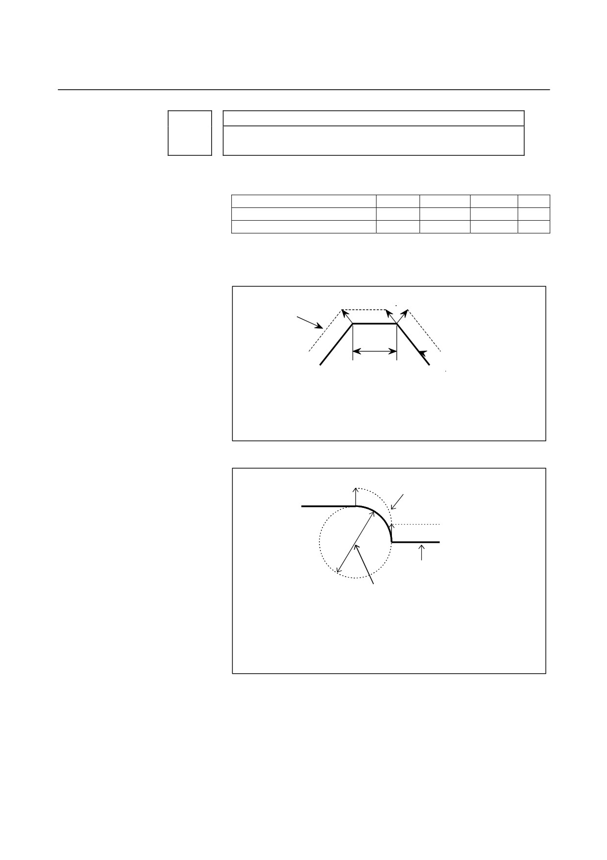
N2
Tool center path
N3
N1
Movement
Programmed path
For straight line
Block N2 is machined with the tool being normal to block
N1 when the movement of N2 in the figure on the left does
not exceed the set value.
Fig.4.27 (a) When the Block Moves Along a Straight Line
N1
N2
Tool center path
N3
Programmed path
Diameter
For arc
Arc N2 is machined with the tool being normal to
block N1 when the arc diameter of N2 in the figure on
the left does not exceed the setting value. A normal
direction axis is not controlled to move in the normal
direction according to the arc movement.
Fig.4.27 (b) When the Block Moves Along on Arc
- 282 -
B-64120EN/01
4.DESCRIPTION OF PARAMETERS
#7
#6
#5
#4
#3
#2
#1
#0
5484
ANM
CTI
SDC
[Data type]
Bit
SDC
In normal direction control:
0 : A C-axis movement is automatically inserted between blocks so
that the C-axis is directed at right angles to the direction of
motion at the start point of each block. (After movement on the
C-axis, movement (along the X-axis and Y-axis) specified by the
block is performed.)
1 : If the amount of C-axis movement is smaller than the value set in
parameter
No.5485, a C-axis movement is not inserted before a block. Instead, it
is performed together with movement along the X-axis and Y-axis.
CTI
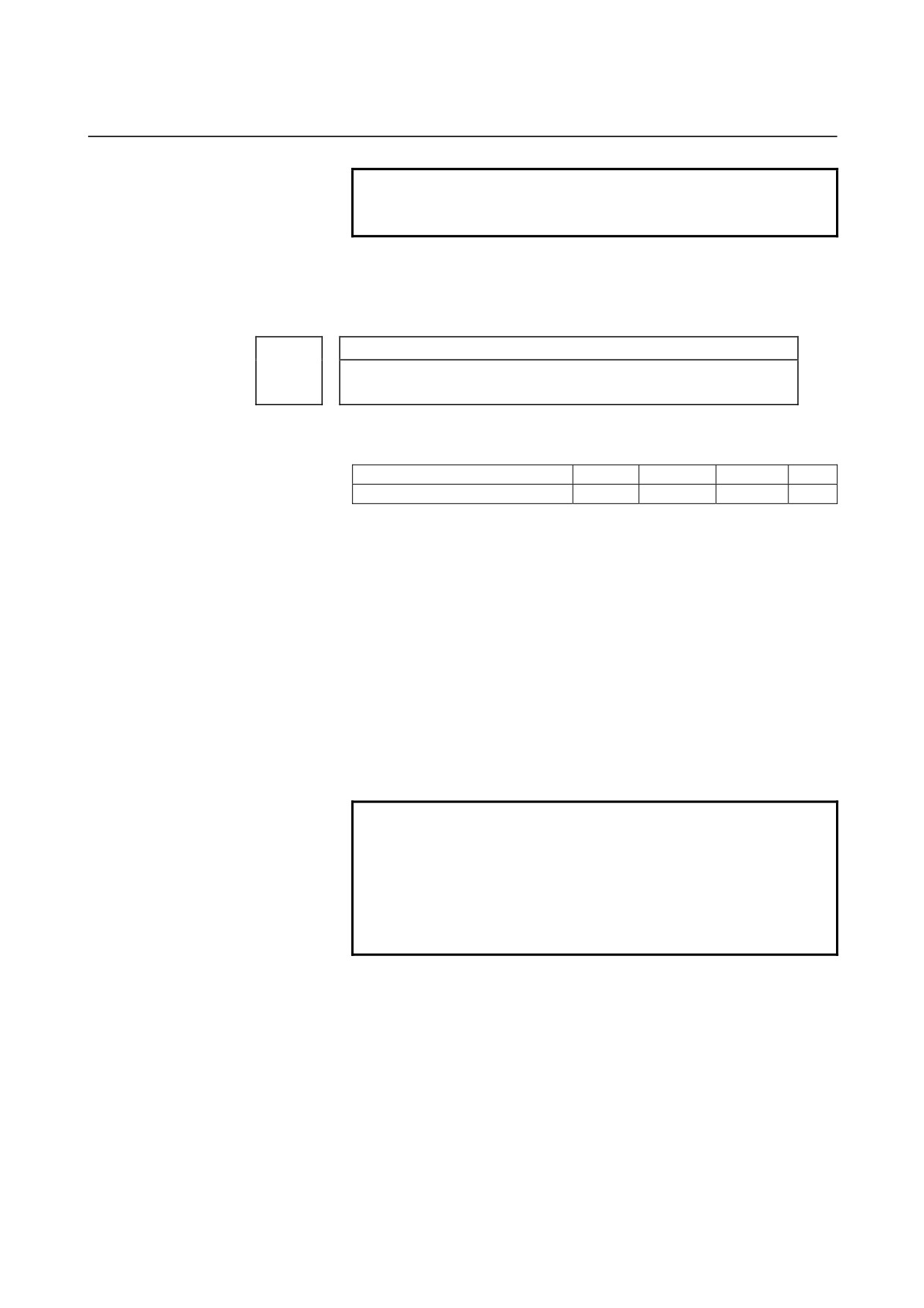
If such an arc that the vector from the center of the arc to a start point
rotates in the reverse direction after cutter compensation is specified
during normal direction control in the cutter compensation C mode:
0 : P/S 041 alarm is issued.
1 : The command is executed.
If this parameter is set to 1, and such an arc that the vector from the
center of the arc to a start point rotates in the reverse direction after
cutter compensation is specified during normal direction control in the
cutter compensation C mode (see the tool path from (4) to (5) in the
figure below), the tool is controlled so that the tool faces in the
direction at right angles to the move direction (programmed path)
before cutter compensation (see the tool path from (2) to (3) in the
figure below).
Thus, as shown by the programmed path from (4) to (5) in the figure
below, the inside of an arc where the radius of the workpiece is
smaller than the compensation value of the tool can be cut.
Path after cutter compensation
(3)
(1)
(5)
Tool
(2)
(4)
Programmed path
Workpiece
(6)
- 283 -
4.DESCRIPTION OF PARAMETERS
B-64120EN/01
NOTE
When this parameter is set to 1, no interference
check is made in cutter compensation C.
ANM In AI contour control mode, the normal direction control function is:
0 : Disabled.
1 : Enabled.
5485
Limit imposed on the insertion of a single block for rotation about the
normal direction control axis
[Data type]
2-word
[Unit of data]
Input increment
IS-A
IS-B
IS-C
Unit
Rotation axis
0.01
0.001
0.0001
deg
[Valid data range]
1 to 99999999
When normal direction control is applied, the amount of movement
(rotation angle) on the normal direction control axis
(C-axis),
calculated so that the C-axis is directed at right angles to the direction
of motion at the start point of a block, may be smaller than the value
specified in this parameter. In such a case, the C-axis movement is
not inserted before the movement
(along the X-axis and Y-axis)
specified by the block. Instead, the C-axis movement is performed
together with the movement specified by the block. If the amount of
movement (rotation angle) on the C-axis is greater than or equal to the
value specified with this parameter, the C-axis movement is inserted,
and the movement specified by the block is made after the completion
of the C-axis movement.
NOTE
This parameter is enabled when the SDC
parameter (bit 0 of parameter No.5484) is set to 1.
If a value equal to or greater than 180 degrees is
specified, a C-axis movement is inserted only when
circular interpolation involving a C-axis rotation of
180 degrees or more is performed.
- 284 -

B-64120EN/01
4.DESCRIPTION OF PARAMETERS
4.28
PARAMETERS OF INDEXING INDEX TABLE
#7
#6
#5
#4
#3
#2
#1
#0
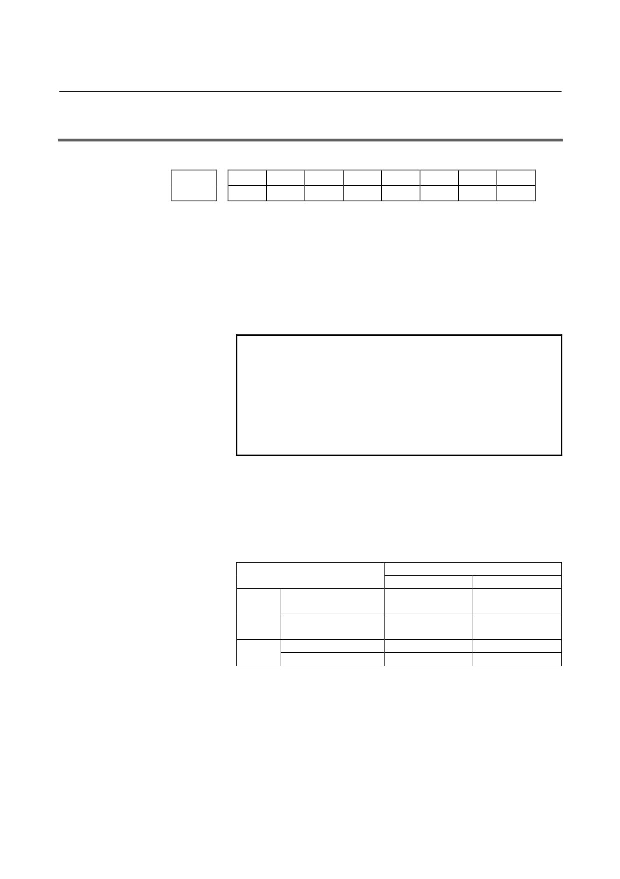
5500
IDX
SIM
G90
INC
ABS
REL
DDP
[Data type]
Bit
DDP
Selection of decimal-point input method of index table indexing axis
0 : Conventional method (Example IS-B: B1; = 0.001 deg)
1 : Pocket calculator method (Example IS-B: B1; = 1.000 deg)
REL
Relative position display of index table indexing axis
0 : Not rounded by 360 degrees
1 : Rounded by 360 degrees
ABS
Displaying absolute coordinate value of index table indexing axis
0 : Not rounded by 360 degrees
The index table indexing axis rotates 720 degrees (two rotations)
when G90 B720.0; is specified from the 0-degree position. It
rotates in reverse direction 720 degrees (two rotations) when G90
B0.; is specified. The absolute coordinate value then becomes 0
degree.
1 : Rounded by 360 degrees
The index table indexing axis is positioned in 40 degrees when
G90 B400.0; is specified from the 0-degree position. The index
table indexing axis does not rotate by two or more turns when
this parameter is set to
1. It also does not move when G90
B720.0; is specified from the 0-degree position.
INC
Rotation in the G90 mode when negative-direction rotation command
M code (parameter No.5511) is not set
0 : Not set to the shorter way around the circumference
1 : Set to the shorter way around the circumference
(Set ABS, #2
of parameter No.5500, to 1.)
G90
Index table indexing command
0 : Judged to be an absolute/increment command according to the
G90/G91 mode
1 : Judged to be an absolute command
SIM
When the same block includes a command for an index table indexing
axis and a command for another controlled axis:
0 : A P/S alarm (No.136) is issued.
1 : The commands are executed.
(In a block other than G00, G28,
and G30, however, a P/S alarm (No.136) is issued.)
IDX
Index table indexing sequence
0 : Type A
1 : Type B
- 285 -
4.DESCRIPTION OF PARAMETERS
B-64120EN/01
#7
#6
#5
#4
#3
#2
#1
#0
5501
ISP
ITI
[Data type]
Bit
ITI
The index table index function is:
0 : Enabled.
1 : Disabled.
ISP
For the index table axis, an automatic servo-off operation when
clamping is completed and an automatic servo-on operation when
unclamping is completed are:
0 : Performed.
1 : Not performed.
5511
Negative-direction rotation command M code
[Data type]
2-word
[Valid data range]
0 to 255
0 : Not use an M code that sets the index table rotation to the
negative direction. The rotation direction is specified using a
command and parameter (INC, #3 of parameter No.5500).
1 to 255:
Sets an M code that sets the index table rotation to the negative
direction. The rotation is set to the negative direction only when
an M code set here is specified in the same block as an index
table indexing command. If the M code is not specified in the
same block, the rotation is always set to the positive direction.
NOTE
Set ABS, #2 of parameter No.5500, to 1.
5512
Unit of index table indexing angle
[Data type]
2-word
[Unit of data]
Input increment
IS-A
IS-B
IS-C
Unit
Rotation axis
0.01
0.001
0.0001
deg
[Valid data range]
0 to 360000
This parameter sets the unit of index table indexing angle. A P/S alarm
(No.135) generated when movementother than integer multiple of the
setting value is specified.
NOTE
If zero is specified as the setting value, any
command can be specified irrespective of the unit
of angle.
- 286 -
B-64120EN/01
4.DESCRIPTION OF PARAMETERS
4.29
PARAMETERS OF CUSTOM MACROS
#7
#6
#5
#4
#3
#2
#1
#0
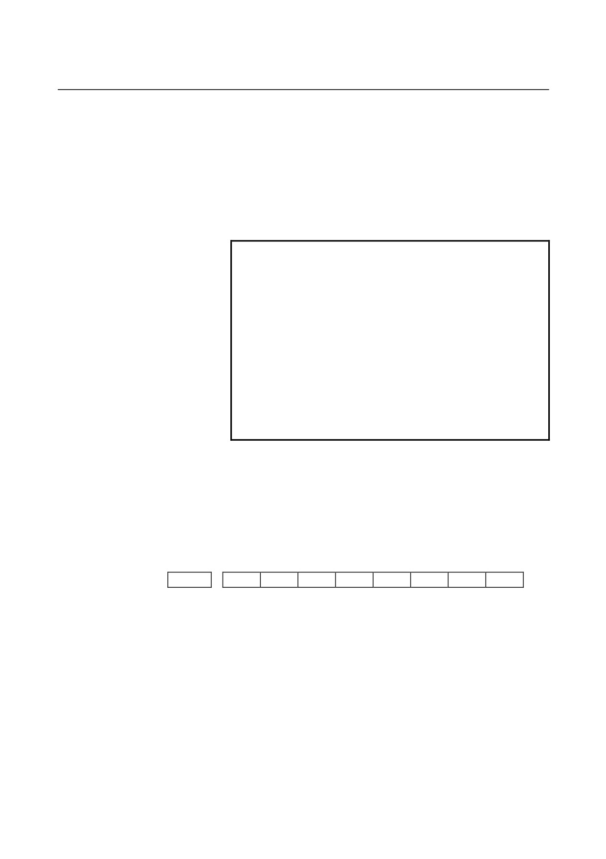
SBV
SBM
HGO
HMC
G67
6000
SBV
SBM
HGO
V15
HMC
G67
[Data type]
Bit
G67
If the macro continuous-state call cancel command (G67) is specified
when the macro continuous-state call mode (G66) is not set:
0 : P/S alarm No.122 is issued.
1 : The specification of G67 is ignored.
HMC
A custom macro is executed:
0 : At a normal speed.
1 : At a high speed.
NOTE
When this parameter is set, the CNC executes a
custom macro first. For this reason, when this
parameter is set, performance of the following
functions may be degraded:
• Screen display of CNC
• Macro executor (excluding execution macros)
• Embedded Ethernet
V15
As system variable numbers for tool offset:
0 : The standard system variable numbers for the Series 16 are used.
1 : The same system variable numbers as those used for the Series
15 are used.
The tables below indicate the system variables for tool offset numbers
1 to 999. The values for tool offset numbers 1 to 200 can be read from
or assigned to the system variables in parentheses.
System parameter number
V15 = 0
V15 = 1
#11001 to #11999
#10001 to #10999
Geometry offset value
(#2201 to #2400)
(#2001 to #2200)
H-Code
#10001 to #10999
#11001 to #11999
Wear offset value
(#2001 to #2200)
(#2201 to #2400)
Geometry offset value
#13001 to #13999
#12001 to #12999
D-Code
Wear offset value
#12001 to #12999
#13001 to #13999
HGO
When a GOTO statement for specifying custom macro control is
executed:
0 : A high-speed branch is not caused to 30 sequence numbers,
immediately following the point of execution.
1 : A high-speed branch is caused to
30 sequence numbers,
immediately before the point of execution.
- 287 -
4.DESCRIPTION OF PARAMETERS
B-64120EN/01
SBM
Custom macro statement
0: Not stop the single block
1: Stops the single block
If you want to disable the single blocks in custom macro statements
using system variable #3003, set this parameter to 0. If this parameter
is set to 1, the single blocks in custom macro statements cannot be
disabled using system variable #3003. To control single blocks in
custom macro statements using system variable #3003, use bit 7
(SBV) of parameter No. 6000.
NOTE
1 This bit is invalid when bit 0 (NOP) of parameter
No. 3404 is set to 1. (M series)
2 When the block look-ahead operation is enabled, a
block look-ahead operation is performed also in
single block operation, so macro statements are
executed when they are read by the look-ahead
operation.
3 In cutter offset C mode, an intersection on the path
resulting from offsetting is calculated. So, a block
look-ahead operation is performed also in single
block operation. To stop a macro statement in
single block mode, cancel cutter offset C mode in
advance.
SBV
Custom macro statement
0 : Not stop the single block
1 : Stops the single block
To control single blocks in custom macro statements using system
variable #3003, use this parameter to enable or disable single blocks in
custom macro statements.
This bit is valid when bit 5 (SBM) of parameter No. 6000 is set to 0.
#7
#6
#5
#4
#3
#2
#1
#0
6001
CLV
CCV
TCS
CRO
PV5
PRT
MIF
[Data type]
Bit
MIF
The system variable numbers of custom macro interface signals are:
0 : Not expanded.
1 : Expanded.
PRT
Reading zero when data is output using a DPRINT command
0 : Outputs a space
1 : Outputs no data
PV5
Custom macro common variables:
0 : Nos. 500 to 599 are output.
1 : Nos. 100 to 199 and Nos. 500 to 599 are output.
CRO
ISO code in BPRWT or DPRNT command
0 : Outputs only LF after data is output
1 : Outputs LF and CR after data is output
TCS
Subprogram
0 : Not called using a T code
- 288 -

B-64120EN/01
4.DESCRIPTION OF PARAMETERS
1 : Called using a T code
CCV
Custom macro's common variables Nos. 100 to 199
0: Cleared to "vacant" by reset
1: Not cleared by reset
CLV
Custom macro's local variables Nos. 1 to 33
0: Cleared to "vacant" by reset
1: Not cleared by reset
#7
#6
#5
#4
#3
#2
#1
#0
6003
MUS
MCY
MSB
MPR
TSE
MIN
MSK
NOTE
When this parameter is set, the power must be
turned off before operation is continued.
[Data type]
Bit
MSK
Absolute coordinates at that time during custom macro interrupt
0 : Not set to the skip coordinates (system variables #5061 and later)
1 : Set to the skip coordinates (system variables #5061 and later)
MIN
Custom macro interrupt
0 : Performed by interrupting an in-execution block (Custom macro
interrupt type I)
1 : Performed after an in-execution block is completed
(Custom
macro interrupt type II)
TSE
Custom macro interrupt signal UINT <G053#3>
0 : Edge trigger method (Rising edge)
1 : Status trigger method
MPR
Custom macro interrupt valid/invalid M code
0 : M96/M97
1 : M code set using parameters (Nos. 6033 and 6034)
MSB
Interrupt program
0 : Uses a dedicated local variable
(Macro-type interrupt)
1 : Uses the same local variable as in the main program
(Subprogram- type interrupt)
MCY
Custom macro interrupt
0 : Not performed during cycle operation
1 : Performed during cycle operation
MUS
Interrupt-type custom macro
0 : Not used
1 : Used
- 289 -
4.DESCRIPTION OF PARAMETERS
B-64120EN/01
#7
#6
#5
#4
#3
#2
#1
#0
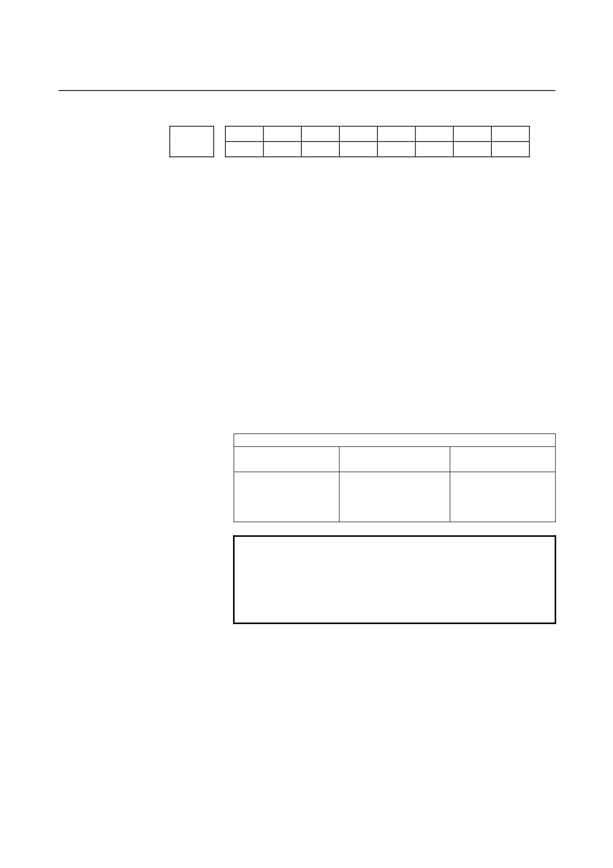
VHD
MFZ
NAT
6004
D15
MFZ
NAT
[Data type]
Bit
NAT
Specification of the results of custom macro functions ATAN
0 : The result of ATAN is 0 to 360.0.
1 : The result of ATAN is -180 to 0 to 180.0.
MFZ
If the angle of a custom macro operation command SIN, COS, or TAN
is 1.0 × 10⁻⁸ or below or if the result of operation is not accurately 0,
the operation result is:
0: Handled as underflow.
1: Normalized to 0.
VHD
With system variables #5121 through #5128
0 : Tool position offset values (geometry offset values) are read.
1 : The amount of interrupt shift caused by a manual handle
interrupt is read.
D15
When tool compensation memory C is used, for reading or writing
tool offset values (for up to offset number 200) for D code (tool
radius), the same system variables, #2401 through #2800, as Series 15
are:
0 : Not used.
1 : Used.
D code
Tool wear
Offset number
Geometry offset value
compensation value
1
#2401
#2601
2
#2402
#2602
:
:
:
200
#2600
#2800
NOTE
When the D15 parameter is set to 1, system
variables #2500 through #2806, for workpiece
reference point offset values, cannot be used.
Instead, use system variables #5201 through
#5324.
- 290 -
B-64120EN/01
4.DESCRIPTION OF PARAMETERS
#7
#6
#5
#4
#3
#2
#1
#0
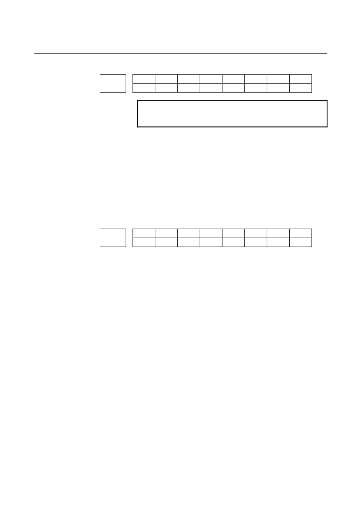
SQC
6005
ADR
SQC
NOTE
When this parameter has been set, the power must
be turned off before operation is continued.
[Data type]
Bit
SQC
Calling a subprogram with its sequence number by the subprogram
call function is:
0 : Disabled.
1 : Enabled.
ADR
Calling a subprogram with address E by the subprogram call function
using a custom macro and macro executor special code is:
0 : Disabled.
1 : Enabled.
Address E can be set for parameters Nos. 6090 and 6091.
#7
#6
#5
#4
#3
#2
#1
#0
MLG
6006
MMG
MLG
[Data type]
Bit
MLG
In conditional decision statements in custom macros, logical
operations:
0 : Cannot be used.
1 : Can be used.
MMG
With system variables
(#4001 to
#4022) for reading modal
information:
0 : Modal information specified in the previous blocks up to the
immediately preceding one can be read.
1 : Modal information of the currently executed block can be read.
- 291 -