FANUC Series 0i-MODEL C, Series 0i Mate-MODEL C. PARAMETER MANUAL (B-64120EN/01) - page 2
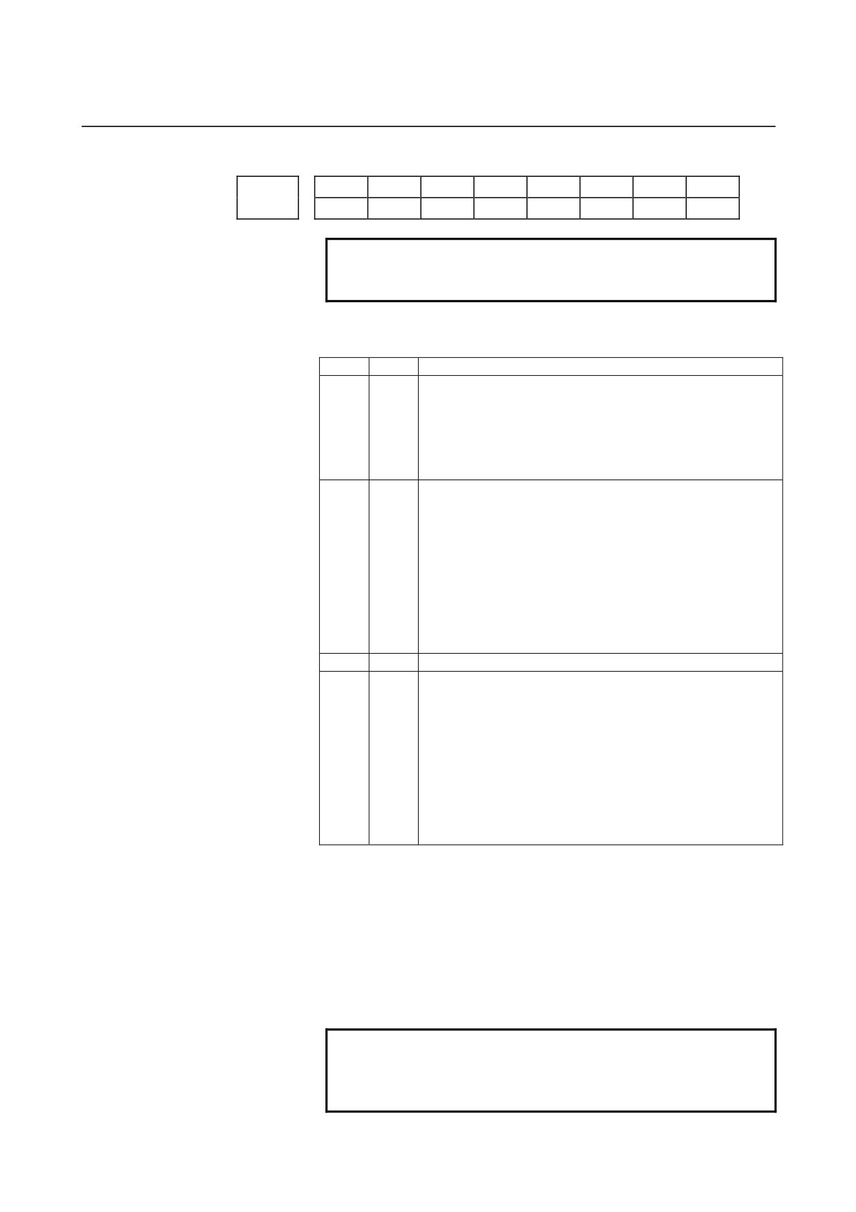
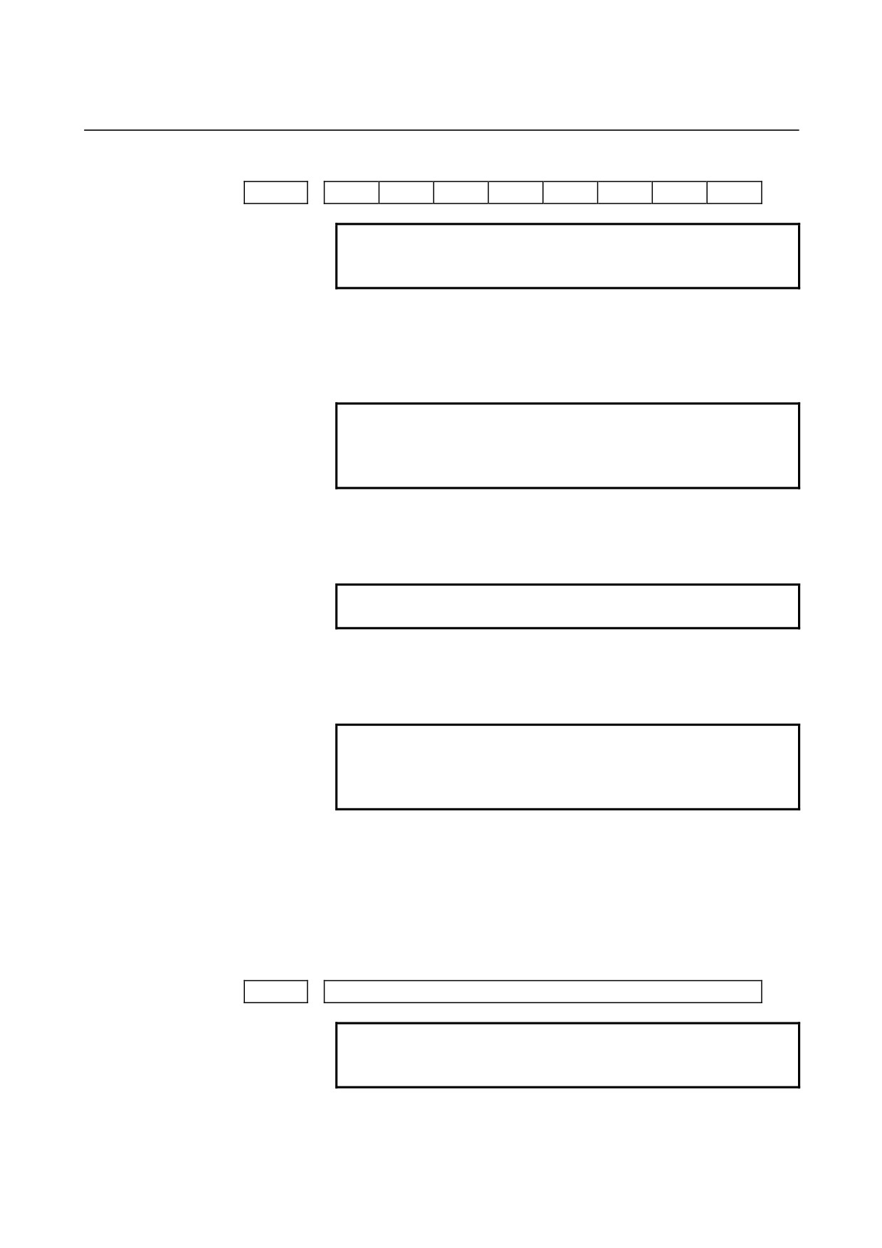
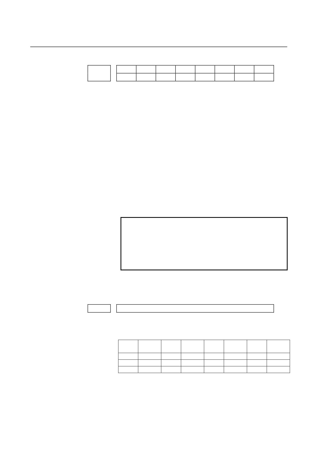
4.DESCRIPTION OF PARAMETERS
B-64120EN/01
4.3
PARAMETERS OF DNC2 INTERFACE
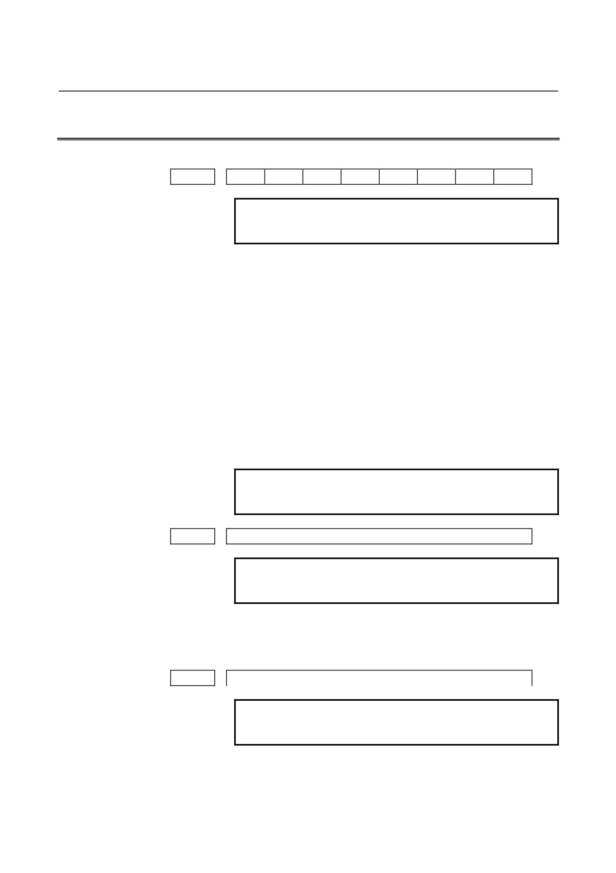
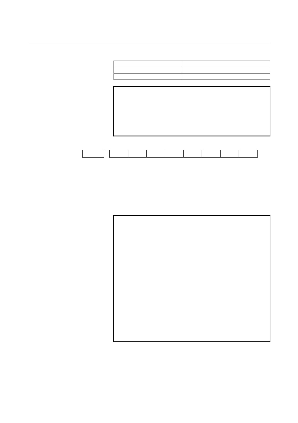
#7
#6
#5
#4
#3
#2
#1
#0
0140
ECD
NCE
BCC
NOTE
When this parameter is set, the power must be
turned off before operation is continued.
[Data type]
Bit
BCC
The BCC value (block check characters) for the DNC2 interface is:
0: Checked.
1: Not checked.
Even if the BCC value is not checked, the BCC value itself must be
specified.
NCE
The ER (RS-232-C) and TR (RS422) signals are:
0: Checked.
1: Not checked.
This parameter is dedicated to the DNC2 interface.
ECD
Error code of negative acknowledgment
0: A four-digit hexadecimal error code is added to a negative
acknowledgment.
1: No error code is added to a negative acknowledgment.
This parameter is dedicated to the DNC2 interface.
NOTE
To use FANUC DNC2 communications library for
the host computer, set this parameter to 1.
0143
Time limit specified for the timer monitoring a response (DNC2 interface)
NOTE
When this parameter is set, the power must be
turned off before operation is continued.
[Data type]
Byte
[Unit of data]
sec
[Valid data range]
1 to 60 (The standard setting is 3.)
0144
Time limit specified for the timer monitoring the EOT signal (DNC2 interface)
NOTE
When this parameter is set, the power must be
turned off before operation is continued.
[Data type] Byte
[Unit of data] sec
[Valid data range]
1 to 60 (The standard setting is 5.)
- 22 -

B-64120EN/01
4.DESCRIPTION OF PARAMETERS
0145
Time required for switching RECV and SEND (DNC2 interface)
NOTE
When this parameter is set, the power must be
turned off before operation is continued.
[Data type] Byte
[Unit of data] sec
[Valid data range]
1 to 60 (The standard setting is 1.)
0146
Number of times the system retries holding communication (DNC2 interface)
NOTE
When this parameter is set, the power must be
turned off before operation is continued.
[Data type]
Byte
[Unit of data]
sec
[Valid data range]
1 to 10 (The standard setting is 3.)
Set the maximum number of times the system retries holding
communication with the remote device if the remote device uses an
invalid protocol in the data-link layer or the remote device does not
respond to the request.
Number of times the system sends the message in response to the NAK
0147
signal (DNC2 interface)
NOTE
When this parameter is set, the power must be
turned off before operation is continued.
[Data type]
Byte
[Unit of data]
Number of times
[Valid data range]
1 to 10 (The standard setting is 2.)
Set the maximum number of times the system retries sending the
message in response to the NAK signal.
0148
Number of characters in overrun (DNC2) interface)
NOTE
When this parameter is set, the power must be
turned off before operation is continued.
[Data type]
Byte
[Valid data range]
10 to 225 (The standard setting is 10.)
Set the number of characters the system can receive after transmission
is stopped (CS off).
- 23 -
4.DESCRIPTION OF PARAMETERS
B-64120EN/01
Number of characters in the data section of the communication packet
0149
(DNC2 interface)
NOTE
When this parameter is set, the power must be
turned off before operation is continued.
[Data type] Word
[Valid range]
80 to 256 (The standard setting is 256.)
The standard setting is 256. If the specified value is out of range, a
value of 80 or 256 is used.
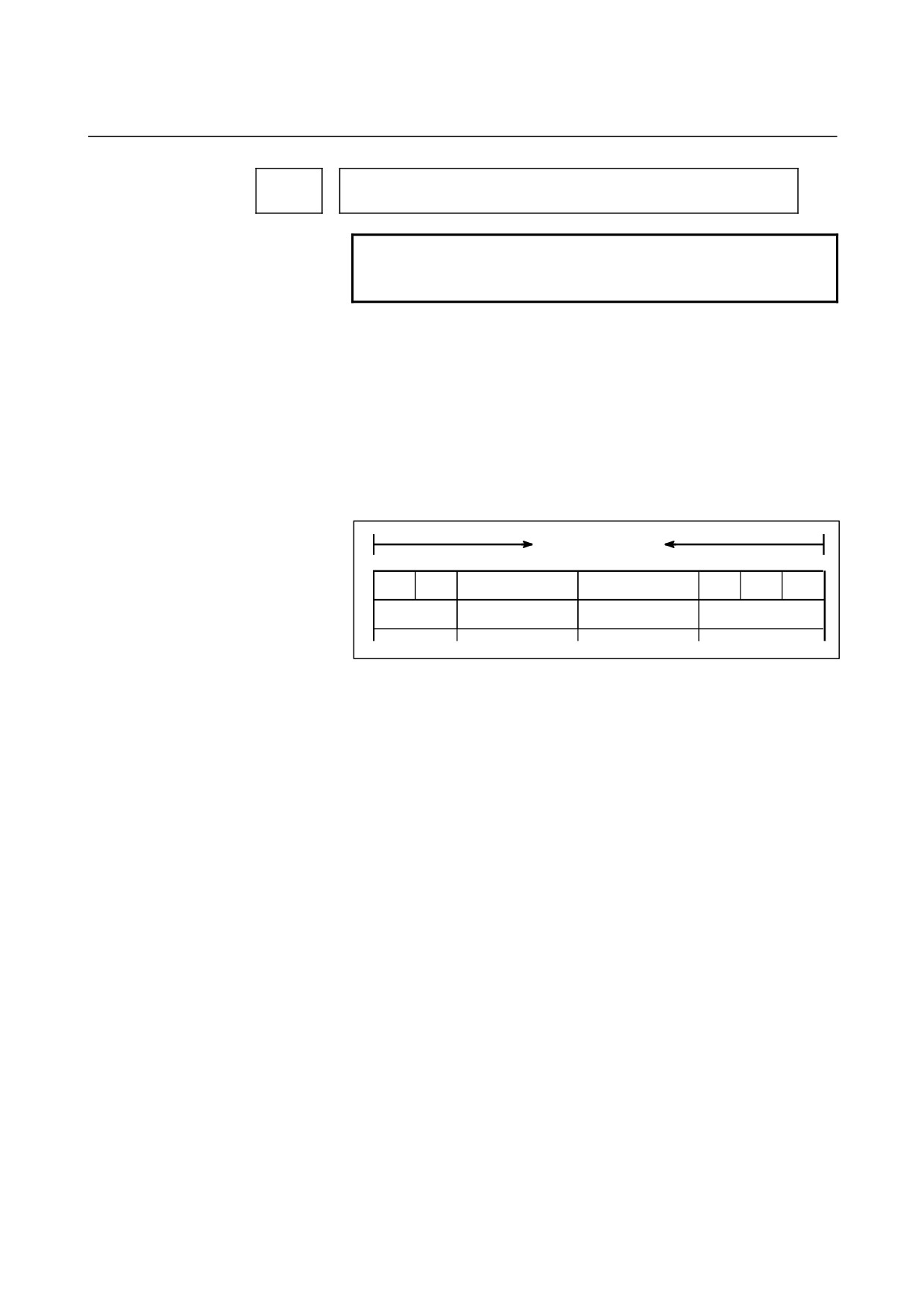
This parameter determines the maximum length of the packet used in
transmission over the DNC2 interface. Including the two characters at
the start of the packet, the four characters used for a command, and the
three characters at the end, the maximum number of characters in the
packet is nine plus the number specified in parameter No.0149.
Length of the packet
DLE
STX
Command
Data section
DEL
ETX
BCC
2 bytes
4 bytes
80 to 256 bytes
3 bytes
- 24 -
B-64120EN/01
4.DESCRIPTION OF PARAMETERS
4.4
PARAMETERS OF REMOTE DIAGNOSIS
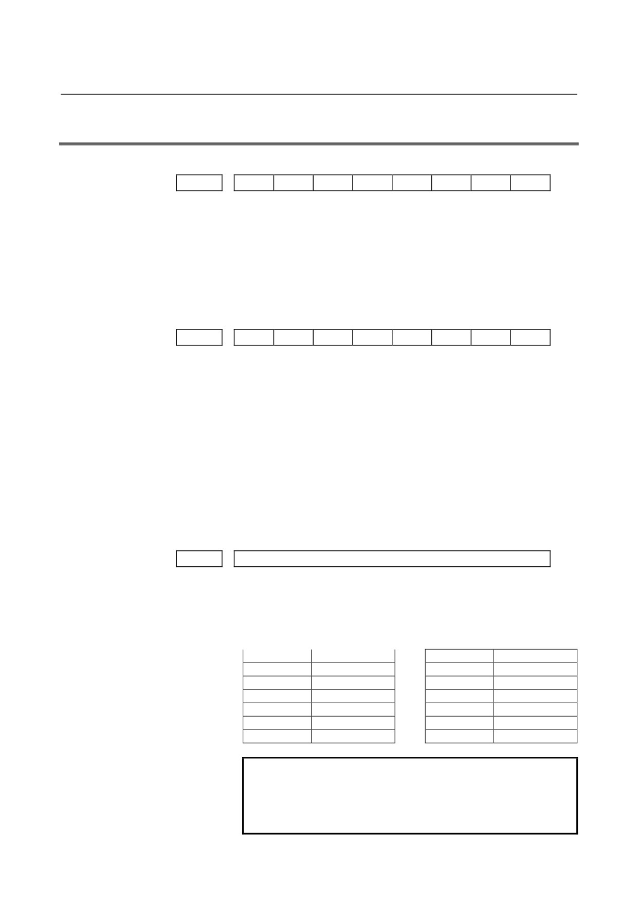
#7
#6
#5
#4
#3
#2
#1
#0
0002
RDG
[Data type]
Bit
RDG
Remote diagnosis is:
0: Not performed.
1: Performed.
If an RS-232-C serial port is used to carry out remote diagnosis,
connect and set up the modem, cable, and the like, then set 1 in this
parameter.
#7
#6
#5
#4
#3
#2
#1
#0
0201
NCR
ASC
SB2
[Data type]
Bit
SB2
The number of stop bits is
0:
1.
1:
2.
To carry out remote diagnosis, set 0.
ASC
The code to be used for data output is:
0: ISO code.
1: ASCII code.
To carry out remote diagnosis, set 1.
NCR
EOB (end of block) is output as:
0: "LF""CR""CR".
1: Just as "LF".
To carry out remote diagnosis, set 1.
0203
Baud rate (for remote diagnosis)
[Data type]
Byte
Set the baud rate of data input/output by remote diagnosis,
with
reference to the tables given below.
When using an RS-232-C serial port
Set value
Baud rate (bps)
Set value
Baud rate (bps)
1
50
7
600
2
100
8
1200
3
110
9
2400
4
150
10
4800
5
200
11
9600
6
300
12
19200
NOTE
The tables above indicate the baud rates of
communication between the CNC and modem. The
actual communication baud rate may be lowered,
depending on the modem and communication line.
- 25 -
4.DESCRIPTION OF PARAMETERS
B-64120EN/01
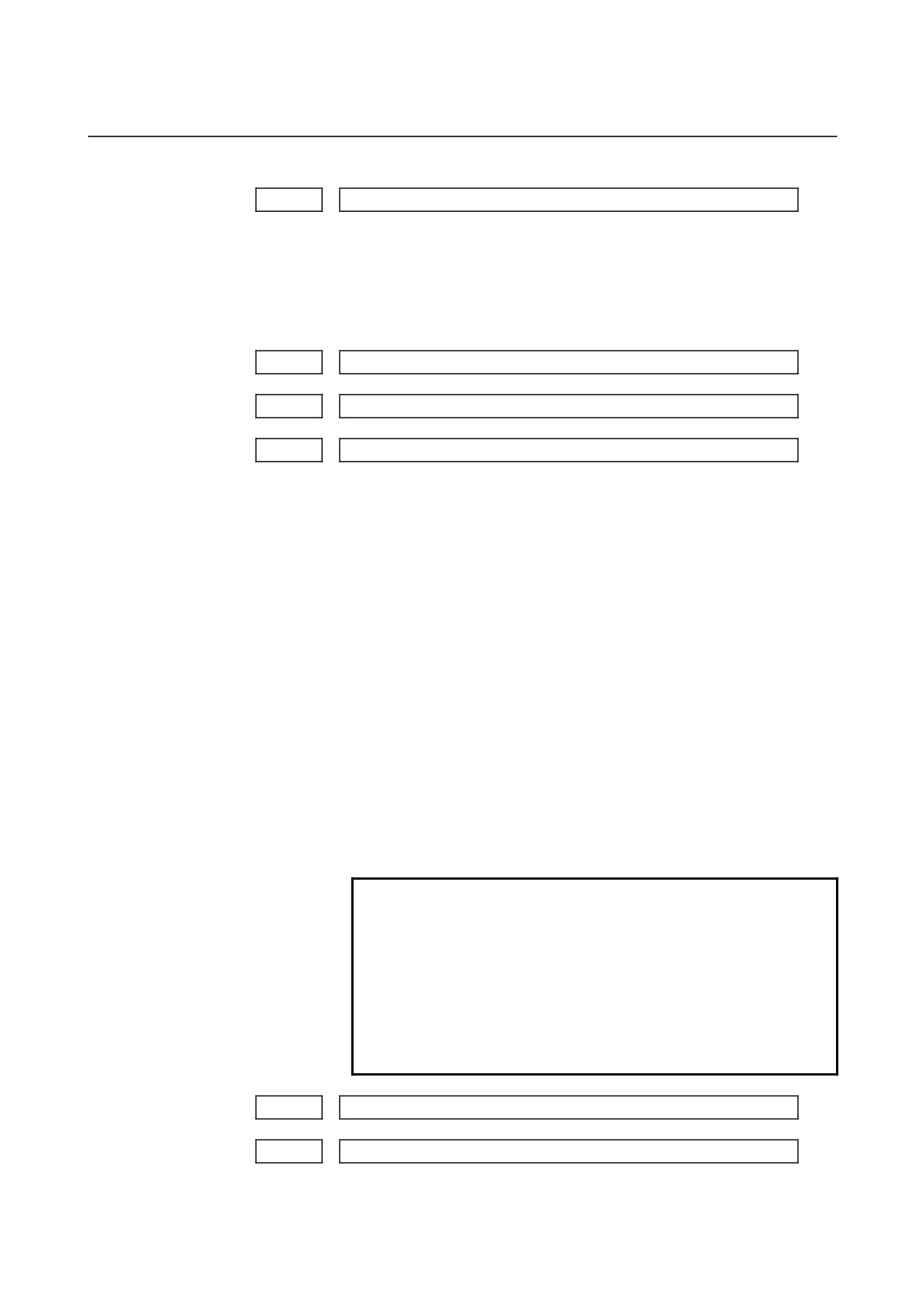
0204
Remote diagnosis channel
[Data type]
Byte
[Valid data range]
0, 1, 2
The interface to be used for remote diagnosis is:
0,1 : RS-232-C serial port 1 (channel 1).
2 : RS-232-C serial port 2 (channel 2).
0211
Password 1 for remote diagnosis
0212
Password 2 for remote diagnosis
0213
Password 3 for remote diagnosis
[Data type]
2-word
[Valid data range]
1 to 99999999
Specify a password for using the remote diagnosis function.
The remote diagnosis function has the following password settings.
Data can be protected by preventing a third party from accessing any
system parameter or machining program without permission.
Password 1:
Set a password for the whole service of the remote diagnosis
function. (The whole remote diagnosis service is available only
when this password is input on the host side (PC, for instance).)
Password 2:
Set a password of a part program. (The input/output, verification,
and the like of a program are possible only when this password is
input on the host side (PC, for instance).)
Password 3:
Set a password of a parameter. (The input/output or the like of a
parameter is possible only when this password is input on the
host side (PC, for instance).)
NOTE
Once any value other than 0 is specified as a
password, the password can be changed only
when the same value is specified in the
corresponding keyword (parameters No. 221 to No.
223). If any value other than 0 is specified as a
password, the password setting is not displayed on
the parameter screen (blank display is provided).
Take great care when setting the password.
0221
Keyword 1 for remote diagnosis
0222
Keyword 2 for remote diagnosis
- 26 -

B-64120EN/01
4.DESCRIPTION OF PARAMETERS
0223
Keyword 3 for remote diagnosis
[Data type]
2-word
[Valid range]
1 to 99999999
Set a keyword corresponding to a password of the remote diagnosis
function.
Keyword 1: Keyword for password 1 (parameter No. 211)
Keyword 2: Keyword for password 2 (parameter No. 212)
Keyword 3: Keyword for password 3 (parameter No. 213)
If any value other than 0 is specified as a password (parameters No.
211 to No. 213), the password can be changed only when the same
value is specified as the corresponding keyword.
NOTE
The keyword value is reset to 0 at power-up. On
the parameter screen, the keyword setting is not
displayed (blank display is provided).
- 27 -

4.DESCRIPTION OF PARAMETERS
B-64120EN/01
4.5
PARAMETER OF MEMORY CARD INTERFACE
#7
#6
#5
#4
#3
#2
#1
#0
0300
PCM
[Data type] Bit
PCM If the CNC screen display function is enabled, when a memory card
interface is provided on the NC side (HSSB connection),
0 : The memory card interface on the NC side is used.
1 : The memory card interface on the PC side is used.
This parameter is valid when parameter No. 20 is set to 4 (memory
card interface). This parameter is valid only while the CNC screen
display function is active.
- 28 -

B-64120EN/01
4.DESCRIPTION OF PARAMETERS
4.6
PARAMETERS OF DATA SERVER
#7
#6
#5
#4
#3
#2
#1
#0
0900
ONS
DSV
[Data type]
Bit
DSV
The data server function is
0: Enabled
1: Disabled
ONS
When the O number of the data server file name and the O number in
an NC program do not match:
0: The O number of the file name takes priority.
1: The O number in the NC program takes priority.
0921
OS selected for host computer 1 of data server
0922
OS selected for host computer 2 of data server
0923
OS selected for host computer 3 of data server
[Data type]
Word
[Valid data range]
0 to 1
0 : Windows95/98/NT is selected.
1 : UNIX or VMS is selected.
0924
Latency setting for DNC1/Ethernet or FOCAS1/Ethernet
[Data type]
Word
[Unit of data]
ms
[Valid data range]
0 to 255
Set service latency of FOCAS1/Ethernet while FOCAS1/Ethernet is
used together with the data server function.
If a value between 0 and 2 is set, 2 ms is assumed.
- 29 -
4.DESCRIPTION OF PARAMETERS
B-64120EN/01
4.7
PARAMETERS OF ETHERNET
0931
Special character code corresponding to soft key [CHAR-1]
0932
Special character code corresponding to soft key [CHAR-2]
0933
Special character code corresponding to soft key [CHAR-3]
0934
Special character code corresponding to soft key [CHAR-4]
0935
Special character code corresponding to soft key [CHAR-5]
[Data type]
Byte
[Valid data range]
32 to 95
These parameters are provided to allow a special character that is not
provided on the MDI panel but needed in a user name, password, or
login DIR to be input by pressing a soft key on the Ethernet parameter
screen.
If a value other than 0 is input as a parameter, the special character
assigned to the corresponding input soft key [CHAR-1] to [CHAR-5]
is displayed.
The special character codes correspond to the ASCII codes.
Sample special character codes
Special
Special
Special
Code
Code
Code
character
character
character
Blank
32
)
41
<
60
!
33
42
>
62
"
34
+
43
?
63
#
35
,
44
@
64
$
36
-
45
[
91
%
37
46
^
92
&
38
/
47
#
93
'
39
:
58
]
94
(
40
;
59
_
95
- 30 -
B-64120EN/01
4.DESCRIPTION OF PARAMETERS
4.8
PARAMETERS OF POWER MATE CNC MANAGER
#7
#6
#5
#4
#3
#2
#1
#0
0960
ASG
SPW
PMN
MD2
MD1
SLV
[Data type] Bit
SLV When the power mate CNC manager is selected, the screen displays:
0 : One slave.
1 : Up to four slaves with the screen divided into four.
MD1,MD2 These parameters set a slave parameter input/output destination.
MD2
MD1
Input/output destination
0
0
Part program storage
0
1
Memory card
In either case, slave parameters are output in program format.
PMN The power mate CNC manager function is:
0 : Enabled.
1 : Disabled. (Communication with slaves is not performed.)
SPW The power mate CNC manager allows parameters of slaves to be set:
0 : Regardless of the PWE settings.
1 : According to the PWE settings.
ASG Whether the number of bytes allocated to the input/output destination
of the β amplifier with the I/O Link is 16 bytes or not is :
0 : Not checked.
1 : Checked.
- 31 -
4.DESCRIPTION OF PARAMETERS
B-64120EN/01
4.9
PARAMETERS OF AXIS CONTROL/INCREMENT SYSTEM
#7
#6
#5
#4
#3
#2
#1
#0
1001
INM
NOTE
When this parameter is set, the power must be
turned off before operation is continued.
[Data type]
Bit
INM
Least command increment on the linear axis
0 : In mm (metric system machine)
1 : In inches (inch system machine)
#7
#6
#5
#4
#3
#2
#1
#0
IDG
XIK
SFD
DLZ
JAX
1002
IDG
XIK
AZR
SFD
DLZ
JAX
[Data type]
Bit
JAX
Number of axes controlled simultaneously in manual continuous feed,
manual rapid traverse and manual reference position return
0 :
1 axis
1 :
3 axes
DLZ
Function setting the reference position without dog
0 : Disabled
1 : Enabled (enabled for all axes)
NOTE
1 This function can be specified for each axis by
DLZx, bit 1 of parameter No.1005.
2 For a system including an axis of Cs contour
control or spindle positioning, avoid using this
parameter. Use bit 1 (DLZx) of parameter No.
1005 instead to set just a required axis.
SFD
The function for shifting the reference position is
0: Not used.
1: Used.
AZR
When no reference position is set, the G28 command causes:
0: Reference position return using deceleration dogs
(as during
manual reference position return) to be executed.
1: P/S alarm No.090 to be issued.
- 32 -
B-64120EN/01
4.DESCRIPTION OF PARAMETERS
NOTE
When reference position return without dogs is
specified, (when bit 1 (DLZ) of parameter No.1002
is set to 1. The G28 command specified before a
reference position causes P/S alarm No.090,
regardless of the setting of AZR.
XIK
When LRP, bit 1 of parameter No.1401, is set to 0, namely, when
positioning is performed using non-linear type positioning, if an
interlock is applied to the machine along one of axes in positioning,
0: The machine stops moving along the axis for which the interlock
is applied and continues to move along the other axes.
1: The machine stops moving along all the axes.
IDG
When the reference position is set without dogs, automatic setting of
the IDGx parameter (bit 0 of parameter No.1012) to prevent the
reference position from being set again is:
0 : Not performed.
1 : Performed.
#7
#6
#5
#4
#3
#2
#1
#0
IPR
ISC
1004
IPR
IPI
ISC
ISA
NOTE
When this parameter is set, the power must be
turned off before operation is continued.
[Data type]
Bit
ISA, ISC, ISD
The least input increment and least command increment are set.
Least input increment and least command
ISC
ISA
Symbol
increment
0
0
0.001 mm, 0.001 deg, or 0.0001 inch
IS-B
0
1
0.01 mm, 0.01 deg, or 0.001 inch
IS-A
1
0
0.0001 mm, 0.0001 deg, or 0.00001 inch
IS-C
NOTE
IS-A cannot be used at present.
IPI
Bit 7 (IPR) of parameter No. 1004 is:
0 : A parameter that requires a power-off operation to make the
setting valid, and that becomes invalid for inch input.
1 : A parameter that does not require a power-off operation, and that
is also valid for inch input.
IPR
Whether the least input increment for each axis is set to a value 10
times as large as the least command increment is specified, in
increment systems of IS-B or IS-C at setting mm.
0: The least input increment is not set to a value 10 times as large as
the least command increment.
1: The least input increment is set to a value 10 times as large as the
least command increment.
- 33 -
4.DESCRIPTION OF PARAMETERS
B-64120EN/01
If IPR is set to 1, the least input increment is set as follows:
Input increment
Least input increment
IS-B
0.01 mm, 0.01 deg, or 0.0001 inch
IS-C
0.001 mm, 0.001 deg, or 0.00001 inch
NOTE
For IS-A, the least input increment cannot be set to
a value 10 times as large as the least command
increment.
The least input increment is not multiplied by 10
also when the calculator-type decimal point input
(bit 0 (DPI) of parameter No. 3401) is used.
#7
#6
#5
#4
#3
#2
#1
#0
1005
EDMx
EDPx
HJZx
DLZx
ZRNx
[Data type]
Bit axis
ZRNx
When a command specifying the movement except for G28 is issued
in automatic operation (MEM, MDI, or DNC) and when a return to
the reference position has not been performed since the power was
turned on
0 : An alarm is generated (P/S alarm 224).
1 : An alarm is not generated.
NOTE
1 The state in which the reference position has not
been established refers to that state in which
reference position return has not been performed
after power-on when an absolute position detector
is not being used, or that state in which the
association of the machine position with the
position detected with the absolute position
detector has not been completed (see the
description of bit 4 (APZx) of parameter No. 1815)
when an absolute position detector is being used.
2 To use a function that establishes the reference
point and makes a movement with a command
other than G28, such as an axis of Cs contour
control, set this parameter for the relative axis.
3 When the Cs axis coordinate setup function (bit 2
(CSF) of parameter No. 3712) is used, it is
recommended that this parameter be set to 0.
DLZx
Function for setting the reference position without dogs
0 : Disabled
1 : Enabled
- 34 -
B-64120EN/01
4.DESCRIPTION OF PARAMETERS
NOTE
1 When bit 1 (DLZ) of parameter No. 1002 is 0, DLZx
is enabled. When bit 1 (DLZ) of parameter No.
1002 is 1, DLZx is disabled, and the function for
setting the reference position without dogs is
enabled for all axes.
2 Do not set this parameter for the Cs contour control
axis or spindle positioning axis.
HJZx
When a reference position is already set:
0 : Manual reference position return is performed with deceleration
dogs.
1 : Manual reference position return is performed using rapid
traverse without deceleration dogs, or manual reference position
return is performed with deceleration dogs, depending on the
setting of bit 7 (SJZ) of parameter No.0002.
NOTE
When the function (see bit 1 (DLZ) of parameter
No. 1002) for setting the reference position without
dogs is used, positioning to a reference position is
always performed using rapid traverse in reference
position return after establishment of the reference
position, regardless of the setting of HJZ.
EDPx
External deceleration signal in the positive direction for each axis
0 : Valid only for rapid traverse
1 : Valid for rapid traverse and cutting feed
EDMx
External deceleration signal in the negative direction for each axis
0 : Valid only for rapid traverse
1 : Valid for rapid traverse and cutting feed
- 35 -
4.DESCRIPTION OF PARAMETERS
B-64120EN/01
#7
#6
#5
#4
#3
#2
#1
#0
ZMIx
DIAx
ROSx
ROTx
1006
ZMIx
ROSx
ROTx
NOTE
When this parameter is set, the power must be
turned off before operation is continued.
[Data type]
Bit axis
ROTx, ROSx
Setting linear or rotation axis.
ROSx
ROTx
Meaning
0
0
Linear axis
(1) Inch/metric conversion is done.
(2) All coordinate values are linear axis type.
(Is not rounded in 0 to 360°)
(3) Stored pitch error compensation is linear axis type
(Refer to parameter No.3624)
0
1
Rotation axis (A type)
(1) Inch/metric conversion is not done.
(2) Machine coordinate values are rounded in 0 to 360°.
Absolute coordinate values are rounded or not rounded
by parameter No.1008#0(ROAx) and #2(RRLx).
(3) Stored pitch error compensation is the rotation type.
(Refer to parameter No.3624)
(4) Automatic reference position return (G28, G30) is done
in the reference position return direction and the move
amount does not exceed one rotation.
1
0
Setting is invalid (unused)
1
1
Rotation axis (B type)
(1) Inch/metric conversion, absolute coordinate values and
relative coordinate values are not done.
(2) Machine coordinate values, absolute coordinate values
and relative coordinate values are linear axis type. (Is
not rounded in 0 to 360°).
(3) Stored pitch error compensation is linear axis type
(Refer to parameter No.3624)
(4) Cannot be used with the rotation axis roll over function
and the index table indexing function (M series)
For the rotation axis used for cylindrical interpolation, set ROTx to 1.
DIAx
Either a diameter or radius is set to be used for specifying the amount
of travel on each axis.
0 : Radius
1 : Diameter
ZMIx
The direction of reference position return.
0 : Positive direction
1 : Negative direction
NOTE
The direction of the initial backlash, which occurs
when power is switched on, is opposite to the
direction of a reference position return.
- 36 -

B-64120EN/01
4.DESCRIPTION OF PARAMETERS
#7
#6
#5
#4
#3
#2
#1
#0
OKIx
ALZx
RTLx
1007
OKIx
[Data type]
Bit axis
RTLx
The reference position return operation for a rotation axis is:
0 : Of rotation axis type.
1 : Of linear axis type.
NOTE
The rotation axis type reference position return
operation and the linear axis type reference
position return operation differ in behavior as
follows, depending on when the dog (the
deceleration signal for reference position return) is
pressed:
• Linear axis type:
When the dog is pressed before the one-rotation
signal is seized, P/S alarm No. 090 is issued.
• Rotation axis type:
When the dog is pressed before the one-rotation
signal is seized, the reference position return
operation is continued without issuing an alarm.
ALZx
An automatic reference position return operation causes:
0 : A return to the reference position by positioning.
When a reference position return has not been performed even
once since power-on, a return to the reference position is
performed in the same sequence as for the manual reference
position return operation.
1 : A return to the reference position in the same sequence as for the
manual reference position return operation.
NOTE
This parameter has no influence on axes for which
a reference position return is performed without
dogs.
OKIx
In reference position setting by pressing an axis against a stopper,
after a reference position return is completed, P/S alarm 000 is:
0 : Issued.
(If this setting is made, an absolute position detector is required
when the function of reference position setting by pressing an
axis against a stopper is used.)
1 : Not issued.
(If this setting is made, no absolute position detector is required
even when the function of reference position setting by pressing
an axis against a stopper is used.)
- 37 -
4.DESCRIPTION OF PARAMETERS
B-64120EN/01
#7
#6
#5
#4
#3
#2
#1
#0
1008
RMCx
RRLx
RABx
ROAx
NOTE
When this parameter is set, the power must be
turned off before operation is continued.
[Data type]
Bit axis
ROAx
The roll-over function of a rotation axis is
0 : Invalid
1 : Valid
NOTE
ROAx specifies the function only for a rotation axis
(for which ROTx, #0 of parameter No.1006, is set
to 1)
RABx
In the absolute commands, the axis rotates in the direction
0 : In which the distance to the target is shorter.
1 : Specified by the sign of command value.
NOTE
RABx is valid only when ROAx is 1.
RRLx
Relative coordinates are
0 : Not rounded by the amount of the shift per one rotation
1 : Rounded by the amount of the shift per one rotation
NOTE
1 RRLx is valid only when ROAx is 1.
2 Assign the amount of the shift per one rotation in
parameter No.1260.
RMCx
When machine coordinate system selection
(G53) or high-speed
machine coordinate system selection (G53P1) is specified, for the
roll-over function of a rotation axis, the setting of bit 1 (RABx) of
parameter No. 1008, which sets the direction of rotation for absolute
commands, is:
0 : Invalid.
1 : Valid.
1010
Number of CNC-controlled axes
NOTE
When this parameter is set, the power must be
turned off before operation is continued.
[Data type]
Byte
[Valid data range]
1, 2, 3, ..., the number of controlled axes
- 38 -
B-64120EN/01
4.DESCRIPTION OF PARAMETERS
Set the maximum number of axes that can be controlled by the CNC.
Examples
Suppose that the first axis is the X axis, and the second and
subsequent axes are the Y, Z, and A axes in that order, and that
they are controlled as follows:
X, Y, and Z axes: Controlled by the CNC
A axis: Controlled by the PMC
Then set this parameter to 3 (total 3: 1st to 3rd axes)
With this setting, the fourth axis (A axis) is controlled only by
the PMC, and therefore cannot be controlled directly by the
CNC.
- 39 -

4.DESCRIPTION OF PARAMETERS
B-64120EN/01
#7
#6
#5
#4
#3
#2
#1
#0
1012
IDGx
[Data type]
Bit axis
IDGx
The function for setting the reference position again, without dogs, is:
0 : Not inhibited.
1 : Inhibited.
NOTE
1
IDGx is enabled when the IDG parameter (bit 7 of
parameter No.1002) is 1.
2
When the function for setting the reference position
without dogs is used, and the reference position is
lost for some reason, an alarm requesting
reference position return (No.300) is generated
when the power is next turned on. If the operator
performs reference position return, as a result of
mistakenly identifying the alarm as that requesting
the operator to perform a normal reference position
return, an invalid reference position may be set. To
prevent such an operator error, the IDGx
parameter is provided to prevent the reference
position from being set again without dogs.
(1) If the IDG parameter (bit 7 of parameter
No.1002) is set to 1, the IDGx parameter (bit 0
of parameter No.1012) is automatically set to 1
when the reference position is set using the
function for setting the reference position
without dogs. This prevents the reference
position from being set again without dogs.
(2) Once the reference position is prevented from
being set for an axis again, without dogs, any
attempt to set the reference position for the
axis without dogs results in the output of an
alarm (No.090).
(3) When the reference position must be set again
without dogs, set IDGx to 0 before setting the
reference position.
- 40 -
B-64120EN/01
4.DESCRIPTION OF PARAMETERS
#7
#6
#5
#4
#3
#2
#1
#0
DWT
WIC
SVS
ZRL
RHR
1015
DWT
WIC
ZRL
RHR
[Data type]
Bit
RHR
After increment system (inch/metric) switching, for the rotation axis,
the first G28 command causes reference position return:
0 : At a low speed.
1 : At a high speed/
ZRL
For high-speed reference position return according to G28, second to
fourth reference position return according to G30, and G53 command:
0 : Non-linear type positioning is performed.
1 : Linear type positioning is performed.
This parameter is valid when bit 1 (LRP) of parameter No. 1401 is set
to 1.
SVS
When the servo along an axis is turned off, simple synchronous
control is:
0 : Released.
1 : Not released.
WIC
Direct input of measured values for workpiece origin offsets is:
0 : Enabled only in a selected workpiece coordinate system.
1 : Enabled in all coordinate systems.
NOTE
If this parameter is set to 0, measured values can
be input directly only in the currently selected
workpiece coordinate system or external workpiece
coordinate system. If a measured value is input
directly for a workpiece origin offset in another
coordinate system, a warning is issued.
DWT
When a dwell time is specified with P, the unit of data is:
0 :
1 ms for IS-B, or 0.1 ms for IS-C.
1 :
1 ms. (Not depending on the increment system.)
1020
Program axis name for each axis
[Data type]
Byte axis
Set the program axis name for each controlled axis, using one of the
values listed in the following table:
Axis
Setting
Axis
Setting
Axis
Setting
Axis
Setting
name
name
name
name
X
88
U
85
A
65
E
69
Y
89
V
86
B
66
-
-
Z
90
W
87
C
67
-
-
- 41 -

4.DESCRIPTION OF PARAMETERS
B-64120EN/01
NOTE
1
With the T series, when G code system A is used,
neither U, V, nor W can be used as an axis name.
Only when G code system B or C is used, U, V,
and W can be used as axis names.
2
The same axis name cannot be assigned to more
than one axis.
3
When the secondary auxiliary function (option) is
provided, the address used by the secondary
auxiliary function (address B with the T series or,
with the M series, the address specified in
parameter No.3460) cannot be used as an axis
name.
4
With the T series, when address C or A is used for
chamfering, corner rounding, or direct drawing
dimension programming (when the CCR parameter
(bit 4 of parameter No.3405) is set to 1), addresses
C or A cannot be used as an axis name.
5
Only with the T series, address E can be used as
an axis name. Address E cannot be used with the
M series. When address E is used as an axis
name, note the following:
- When G code system A is used, address E is
always assigned to an absolute command.
- When an equal-lead threading command (G32) is
issued in the FS10/11 command format, address
E cannot be used to specify the thread lead. Use
address F to specify the thread lead.
1022
Setting of each axis in the basic coordinate system
NOTE
When this parameter is set, power must be turned
off before operation is continued.
[Data type]
Byte axis
To determine the following planes used for circular interpolation,
cutter compensation C
(for the M series), tool nose radius
compensation (for the T series), etc., each control axis is set to one of
the basic three axes X, Y, and Z, or an axis parallel to the X, Y, or Z
axis.
G17: Plane Xp-Yp
G18: Plane Zp-Xp
G19: Plane Yp-Zp
Only one axis can be set for each of the three basic axes X, Y, and Z,
but two or more parallel axes can be set.
Set value
Meaning
0
Neither the basic three axes nor a parallel axis
1
X axis of the basic three axes
- 42 -

B-64120EN/01
4.DESCRIPTION OF PARAMETERS
Set value
Meaning
2
Y axis of the basic three axes
3
Z axis of the basic three axes
5
Axis parallel to the X axis
6
Axis parallel to the Y axis
7
Axis parallel to the Z axis
1023
Number of the servo axis for each axis
NOTE
When this parameter is set, power must be turned
off before operation is continued.
[Data type]
Byte axis
[Valid data range]
1, 2, 3, ..., number of control axes /-1,-2
Set the servo axis for each control axis.
Usually set to same number as the control axis number.
The control axis number is the order number that is used for setting
the axis-type parameters or axis-type machine signals
To use a controlled axis as a spindle, specify -1.
Setting parameter CSS (bit 7 of parameter No. 3704) to 1 enables the
second serial spindle to be assigned as Cs contour axis.
To use the second serial spindle as the Cs contour axis, set -2.
To use a hypothetical Cs axis for Cs contour control, also make a
setting for spindle assignment.
Refer to FSSB section of CONNECTION MANUAL (Function)
(B-64113EN-1).
- 43 -
4.DESCRIPTION OF PARAMETERS
B-64120EN/01
4.10
PARAMETERS OF COORDINATES
#7
#6
#5
#4
#3
#2
#1
#0
WZR
AWK
ZCL
1201
AWK
ZCL
[Data type]
Bit
ZCL
Local coordinate system when the manual reference position return is
performed
0 : The local coordinate system is not canceled.
1 : The local coordinate system is canceled.
AWK
When the workpiece zero point offset value is changed
0 : The absolute position display changed when the next buffering
block is performed.
1 : The absolute position display is changed immediately. (Valid
when automatic operation is not being started)
Changed value is valid after buffering the next block.
WZR
Upon reset, the workpiece coordinate system is:
0 : Not returned to that specified with G54
1 : Returned to that specified with G54
#7
#6
#5
#4
#3
#2
#1
#0
SNC
RLC
G50
EWS
EWD
1202
SNC
G52
RLC
[Data type]
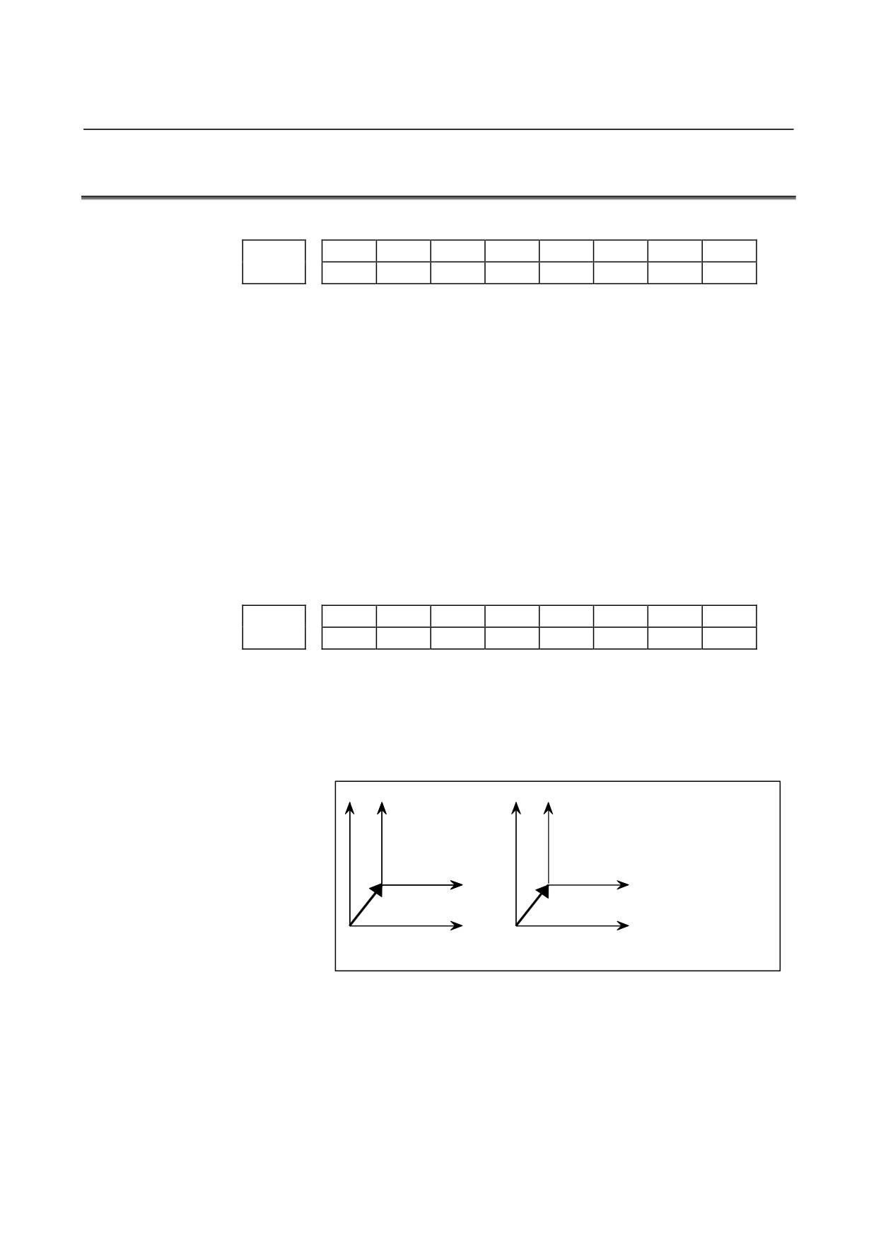
Bit
EWD
The shift direction of the workpiece coordinate system is:
0 : The direction specified by the external workpiece zero point
offset value
1 : In the opposite direction to that specified by the external
workpiece zero point offset value
X
X
X X
EWD=0
EWD=1
Z
Z
(Shifted workpiece
coordinate system)
EXOFS
-EXOFS
Z
(Original workpiece
Z
coordinate system)
EXOFS
:
External workpiece zero point offset value
EWS
Shift value of the workpiece coordinate system and external
workpiece zero point offset value are
0 : Stored in the separate memory areas.
1 : Stored in the same memory area, that is, the shift and the offset
values are the same.
- 44 -

B-64120EN/01
4.DESCRIPTION OF PARAMETERS
G50
If the G50 command for setting a coordinate system (or the G92
command in G command system B or C) is specified,
0 : G50 is executed and no alarm is issued.
1 : G50 is not executed and a P/S alarm (No. 010) is issued.
RLC
Local coordinate system is
0 : Not cancelled by reset
1 : Cancelled by reset
G52
In local coordinate system setting (G52), a cutter compensation vector
is:
0 : Not considered.
1 : Considered.
NOTE
Select a local coordinate system setting operation
when cutter compensation is applied, and when
two or more blocks specifying no movement exist
prior to the specification of G52, or when G52 is
specified after cutter compensation mode is
canceled without eliminating the offset vector.
SNC
After a servo alarm is released, the local coordinate system (G52 or
G92 (M series), or G52 or G50 (T series)) is:
0 : Cleared.
1 : Not cleared.
NOTE
Even when this parameter is set to 1, the local
coordinate system is cleared if a setting is made to
allow the local coordinate system to be canceled by
a reset (bit 3 (RLC) of parameter No. 1202 = 1).
#7
#6
#5
#4
#3
#2
#1
#0
MMD
68A
EMC
1203
MMD
EMC
[Data type]
Bit
EMC
The extended external machine zero point shift function is:
0: Disabled.
1: Enabled.
NOTE
When the extended machine zero point shift
function is enabled, the conventional external
machine zero point shift function is disabled.
68A
In automatic coordinate system setting of an absolute position detector
in the mode of mirror image of facing two posts (G68):
0 : Mirror image of facing two posts is not considered.
1 : Mirror image of facing two posts is considered.
- 45 -
4.DESCRIPTION OF PARAMETERS
B-64120EN/01
MMD
In manual operation, the direction of axis movement for an axis for
which the mirror image function is enabled is:
0 : Not the same direction as in automatic operation.
1 : The same direction as in automatic operation.
#7
#6
#5
#4
#3
#2
#1
#0
R2O
R1O
1205
[Data type]
Bit
R1O
Signal output for the first reference position is:
0 : Disabled.
1 : Enabled.
The reference position signal output function is required. See the
description of parameter No.1245.
R2O
Signal output for the second reference position is:
0 : Disabled.
1 : Enabled.
The reference position signal output function is required. See the
description of parameter No.1246.
1220
External workpiece zero point offset value
[Data type]
2-word axis
[Unit of data]
Input increment
IS-A
IS-B
IS-C
Unit
Linear axis (input in mm)
0.01
0.001
0.0001
mm
Linear axis (input in inches)
0.001
0.0001
0.00001
inch
Rotation axis
0.01
0.001
0.0001
deg
[Valid data range]
-99999999 to 99999999
This is one of the parameters that give the position of the origin of
workpiece coordinate system (G54 to G59). It gives an offset of the
workpiece origin common to all workpiece coordinate systems.
In general, the offset varies depending on the workpiece coordinate
systems. The value can be set from the PMC using the external data
input function.
- 46 -
B-64120EN/01
4.DESCRIPTION OF PARAMETERS
1221
Workpiece zero point offset value in workpiece coordinate system 1 (G54)
1222
Workpiece zero point offset value in workpiece coordinate system 2(G55)
1223
Workpiece zero point offset value in workpiece coordinate system 3(G56)
1224
Workpiece zero point offset value in workpiece coordinate system 4 (G57)
1225
Workpiece zero point offset value in workpiece coordinate system 5 (G58)
1226
Workpiece zero point offset value in workpiece coordinate system 6 (G59)
[Data type]
2-word axis
[Unit of data]
Input increment
IS-A
IS-B
IS-C
Unit
Linear axis (input in mm)
0.01
0.001
0.0001
mm
Linear axis (input in inches)
0.001
0.0001
0.00001
inch
Rotation axis
0.01
0.001
0.0001
deg
[Valid data range]
-99999999 to 99999999
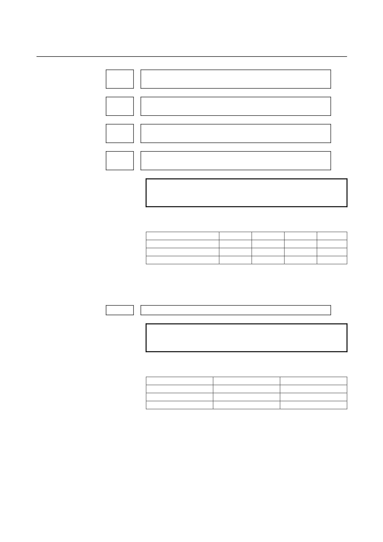
The workpiece zero point offset values in workpiece coordinate
systems 1 to 6 (G54 to G59) are set.
Workpiece coordinate system 1 (G54)
Workpiece coordinate system 2 (G55)
Workpiece zero point offset
Origin of machine coordinate system
NOTE
The workpiece origin offset can also be set using
the workpiece coordinate system screen.
- 47 -
4.DESCRIPTION OF PARAMETERS
B-64120EN/01
Coordinate value of the first reference position on each axis in the machine
1240
coordinate system
Coordinate value of the second reference position on each axis in the
1241
machine coordinate system
Coordinate value of the third reference position on each axis in the machine
1242
coordinate system
Coordinate value of the fourth reference position on each axis in the
1243
machine coordinate system
NOTE
When these parameters are set, power must be
turned off before operation is continued.
[Data type]
2-word axis
[Unit of data]
Increment system
IS-A
IS-B
IS-C
Unit
Millimeter machine
0.01
0.001
0.0001
mm
Inch machine
0.001
0.0001
0.00001
inch
Rotation axis
0.01
0.001
0.0001
deg
[Valid data range]
-99999999 to 99999999
Set the coordinate values of the first to fourth reference
positions in the machine coordinate system.
1260
Amount of a shift per one rotation of a rotation axis
NOTE
When this parameter is set, the power must be
turned off before operation is continued.
[Data type]
2-word axis
[Unit of data]
Increment system
Unit of data
Standard value
IS-A
0.01 deg
36000
IS-B
0.001 deg
360000
IS-C
0.0001 deg
3600000
[Valid data range]
1000 to 99999999
Set the amount of a shift per one rotation of a rotation axis.
For the rotation axis used for cylindrical interpolation, set the standard
value.
- 48 -
B-64120EN/01
4.DESCRIPTION OF PARAMETERS
First address of the signal group used by the external machine zero point
1280
shift extension
[Data type]
Word
[Valid data range]
0 to 65535
Set the first address of the signal group used by the external machine
zero point shift extension. If 100 is specified, R0100 to R0115 can be
used.
Shift amount of external machine zero point shift extension for the
R0100
first axis (LOW)
Shift amount of external machine zero point shift extension for the
R0101
first axis (HIGH)
Shift amount of external machine zero point shift extension for the
R0102
second axis (LOW)
Shift amount of external machine zero point shift extension for the
R0103
second axis (HIGH)
:
:
Shift amount of external machine zero point shift extension for the
R0114
eighth axis (LOW)
Shift amount of external machine zero point shift extension for the
R0115
eighth axis (HIGH)
NOTE
1 If the specified number is not present, the external
machine zero point shift extension is disabled.
2 A shift amount of the external machine zero point
shift extension can be written from the macro
executer.
3 This parameter is valid when bit 0 (EMC) of
parameter No. 1203 is set to 1.
1290
Distance between two opposite tool posts in mirror image
[Data type]
2-word
[Unit of data]
Increment system
IS-A
IS-B
IS-C
Unit
Millimeter machine
0.01
0.001
0.0001
mm
Inch machine
0.001
0.0001
0.00001
inch
[Valid data range]
0 to 99999999
Set the distance between two opposite tool posts in mirror image.
- 49 -

4.DESCRIPTION OF PARAMETERS
B-64120EN/01
4.11
PARAMETERS OF STROKE CHECK
#7
#6
#5
#4
#3
#2
#1
#0
BFA
LZR
RL3
LMS
OUT
1300
BFA
LZR
LMS
OUT
[Data type]
Bit
OUT
The area inside or outside of the stored stroke check 2 is set as an
inhibition area (setting by the parameters No.1322 and No.1323).
0: Inside
1: Outside
LMS
The EXLM <G007#6> signal for switching stored stroke check
0: Disabled
1: Enabled
NOTE
Stored stroke check 1 supports two pairs of
parameters for setting the prohibited area. The
stored stroke limit switching signal is used to
enable either of the prohibited areas set with these
parameter pairs.
(1) Prohibited area I:
Parameters No.1320 and No.1321
(2) Prohibited area II:
Parameters No.1326 and No.1327
RL3
Stored stroke check 3 release signal RLSOT3 <G007#4> is
0: Disabled
1: Enabled
LZR
Checking of stored stroke check 1 during the time from power-on to
the manual position reference return
0: The stroke check 1 is checked.
1: The stroke check 1 is not checked
NOTE
When an absolute position detector is used and a
reference position is already set upon power-up,
stored stroke limit check 1 is started immediately
after power-up, regardless of the setting.
- 50 -

B-64120EN/01
4.DESCRIPTION OF PARAMETERS
BFA
When a command that exceeds a stored stroke check is issued
0: An alarm is generated after the stroke check is exceeded.
1: An alarm is generated before the stroke check is exceeded.
NOTE
The tool stops at a point up to F/7500 mm short of
or ahead of the boundary.
(F: Feedrate when the tool reaches the boundary
(mm/min))
#7
#6
#5
#4
#3
#2
#1
#0
1301
PLC
OTF
OF1
OTA
NPC
DLM
[Data type]
Bit
DLM
The stored stroke limit switching signals <G104, G105> for each axial
direction is:
0: Disabled.
1: Enabled.
NPC
As part of the stroke limit check performed before movement, the
movement specified in G31 (skip) and G37 (automatic tool length
measurement (for M series) or automatic tool compensation (for T
series)) blocks is:
0: Checked
1: Not checked
OTA
If the tool is already in the prohibited area at power-up, an alarm of
stored stroke limit 2 (inside) or stored stroke limit 3 is:
0: Immediately raised.
1: Not raised before a movement is made.
Remark) When the alarm is immediately raised, the system enters the
state before power-down.
If this parameter is set to 1, no alarm is raised before a movement is
made. If the direction of this movement is a direction away from the
prohibited area, movements can be made in the opposite direction only.
Accordingly, there is danger that the tool enters the prohibited area
without an alarm.
OF1
If the tool is moved into the range allowed on the axis after an alarm is
raised by stored stroke check 1,
0: The alarm is not canceled before a reset is made.
1: The OT alarm is immediately canceled.
NOTE
In the cases below, the automatic release function
is disabled. To release an alarm, a reset operation
is required.
1 When a setting is made to issue an alarm before
a stored stroke limit is exceeded (bit 7 (BFA) of
parameter No. 1300)
2 When an another overtravel alarm (such as
stored stroke check 2 and stored stroke check
3) is already issued
- 51 -