FANUC Series 0i-MODEL C, Series 0i Mate-MODEL C. PARAMETER MANUAL (B-64120EN/01) - page 1
B-64120EN/01
PREFACE
PREFACE
The models covered by this manual, and their abbreviations are :
Model name
Abbreviation
FANUC Series 0i -TC
0i -TC
Series 0i -C
0i
FANUC Series 0i -MC
0i -MC
FANUC Series 0i Mate -TC
0i Mate -TC
Series 0i Mate -C
0i Mate
FANUC Series 0i Mate -MC
0i Mate -MC
NOTE
1 For ease of explanation, the models may be
classified as follows:
T series:
0i -TC/0i Mate -TC
M series:
0i -MC/0i Mate -MC
2 Some functions described in this manual may not
be applied to some products.
For details, refer to the DESCRIPTIONS
(B-64112EN).
3 The 0i /0i Mate requires setting of parameters to
enable part of basic functions. For the parameters
to be set, see Section 4.46, "PARAMETERS OF
FS0i BASIC FUNCTIONS".
p-1
PREFACE
B-64120EN/01
Related manuals of Series 0i/0iMate-MODEL C
The following table lists the manuals related to Series
0i/0iMate-MODEL C. This manual is indicated by an asterisk(*).
Related manuals of Series 0i/0iMate-MODEL C
Specification
Manual name
number
DESCRIPTIONS
B-64112EN
CONNECTION MANUAL (HARDWARE)
B-64113EN
CONNECTION MANUAL (FUNCTION)
B-64113EN-1
Series 0i-TC OPERATOR’S MANUAL
B-64114EN
Series 0i-MC OPERATOR’S MANUAL
B-64124EN
Series 0iMate-TC OPERATOR’S MANUAL
B-64134EN
Series 0iMate-MC OPERATOR’S MANUAL
B-64144EN
MAINTENANCE MANUAL
B-64115EN
PARAMETER MANUAL
B-64120EN
*
PMC
PMC Ladder Language PROGRAMMING MANUAL
B-61863E
PMC C Language PROGRAMMING MANUAL
B-61863E-1
Network
Profibus-DP Board OPERATOR'S MANUAL
B-62924EN
FAST Ethernet Board/FAST DATA SERVER
B-63644EN
OPERATOR'S MANUAL
Ethernet Board/DATA SERVER Board OPERATOR'S MANUAL
B-63354EN
DeviceNet Board OPERATOR'S MANUAL
B-63404EN
PC function
Screen Display Function OPERATOR'S MANUAL
B-63164EN
Open CNC
FANUC Open CNC OPERATOR’S MANUAL
B-62994EN
(Basic Operation Package 1(For Windows 95/NT))
FANUC Open CNC OPERATOR’S MANUAL
B-63214EN
(DNC Operation Management Package)
p-2

B-64120EN/01
PREFACE
Related manuals of SERVO MOTOR αis/αi/βis/βi series
The following table lists the manuals
related to SERVO MOTOR
αis/αi/βis/βi series
Specification
Manual name
number
FANUC AC SERVO MOTOR αis series
FANUC AC SERVO MOTOR αi series
B-65262EN
DESCRIPTIONS
FANUC AC SPINDLE MOTOR αi series
B-65272EN
DESCRIPTIONS
FANUC AC SERVO MOTOR βis series
B-65302EN
DESCRIPTIONS
FANUC AC SPINDLE MOTOR βi series
B-65312EN
DESCRIPTIONS
FANUC SERVO AMPLIFIER αi series
B-65282EN
DESCRIPTIONS
FANUC SERVO AMPLIFIER βi series
B-65322EN
DESCRIPTIONS
FANUC SERVO MOTOR αis series
FANUC SERVO MOTOR αi series
FANUC AC SPINDLE MOTOR αi series
B-65285EN
FANUC SERVO AMPLIFIER αi series
MAINTENANCE MANUAL
FANUC SERVO MOTOR βis series
FANUC AC SPINDLE MOTOR βi series
B-65325EN
FANUC SERVO AMPLIFIER βi series
MAINTENANCE MANUAL
FANUC AC SERVO MOTOR αis series
FANUC AC SERVO MOTOR αi series
B-65270EN
FANUC AC SERVO MOTOR βis series
PARAMETER MANUAL
FANUC AC SPINDLE MOTOR αi series
FANUC AC SPINDLE MOTOR βi series
B-65280EN
PARAMETER MANUAL
p-3
B-64120EN/01
TABLE OF CONTENTS
TABLE OF CONTENTS
DEFINITION OF WARNING, CAUTION, AND NOTE
s-1
PREFACE
p-1
1
DISPLAYING PARAMETERS
1
2
SETTING PARAMETERS FROM MDI
3
3
INPUTTING AND OUTPUTTING PARAMETERS THROUGH THE
READER/PUNCHER INTERFACE
5
3.1
OUTPUTTING PARAMETERS THROUGH THE READER/PUNCHER
INTERFACE
6
3.2
INPUTTING PARAMETERS THROUGH THE READER/PUNCHER
INTERFACE
7
4
DESCRIPTION OF PARAMETERS
8
4.1
PARAMETERS OF SETTING
10
4.2
PARAMETERS OF READER/PUNCHER INTERFACE, REMOTE
BUFFER, DNC1, DNC2, AND M-NET INTERFACE
15
4.2.1
Parameters Common to all Channels
16
4.2.2
Parameters of Channel 1 (I/O CHANNEL=0)
17
4.2.3
Parameters of Channel 1 (I/O CHANNEL=1)
19
4.2.4
Parameters of Channel 2 (I/O CHANNEL=2)
19
4.3
PARAMETERS OF DNC2 INTERFACE
22
4.4
PARAMETERS OF REMOTE DIAGNOSIS
25
4.5
PARAMETER OF MEMORY CARD INTERFACE
28
4.6
PARAMETERS OF DATA SERVER
29
4.7
PARAMETERS OF ETHERNET
30
4.8
PARAMETERS OF POWER MATE CNC MANAGER
31
4.9
PARAMETERS OF AXIS CONTROL/INCREMENT SYSTEM
32
4.10
PARAMETERS OF COORDINATES
44
4.11
PARAMETERS OF STROKE CHECK
50
4.12
PARAMETERS OF THE CHUCK AND TAILSTOCK BARRIER
(T SERIES)
56
4.13
PARAMETERS OF FEEDRATE
60
4.14
PARAMETERS OF ACCELERATION/DECELERATION CONTROL
79
4.15
PARAMETERS OF SERVO (1 OF 2)
102
4.16
PARAMETERS OF DI/DO
137
c - 1
TABLE OF CONTENTS
B-64120EN/01
4.17
PARAMETERS OF DISPLAY AND EDIT (1 OF 2)
143
4.18
PARAMETERS OF PROGRAMS
169
4.19
PARAMETERS OF PITCH ERROR COMPENSATION
178
4.20
PARAMETERS OF SPINDLE CONTROL
186
4.21
PARAMETERS OF TOOL COMPENSATION
223
4.22
PARAMETERS OF CANNED CYCLES
235
4.22.1 Parameter of canned Cycle for Drilling
235
4.22.2 Parameter of Thread Cutting Cycle
242
4.22.3 Parameter of Multiple Repetitive Canned Cycle
242
4.22.4 Parameters of Peck Drilling Cycle of a Small Diameter
246
4.23
PARAMETERS OF RIGID TAPPING
251
4.24
PARAMETERS OF SCALING/COORDINATE ROTATION
275
4.25
PARAMETERS OF UNI-DIRECTIONAL POSITIONING
277
4.26
PARAMETERS OF POLAR COORDINATE INTERPOLATION
279
4.27
PARAMETERS OF NORMAL DIRECTION CONTROL
281
4.28
PARAMETERS OF INDEXING INDEX TABLE
285
4.29
PARAMETERS OF CUSTOM MACROS
287
4.30
PARAMETERS OF PATTERN DATA INPUT
296
4.31
PARAMETERS OF SKIP FUNCTION
297
4.32
PARAMETERS OF AUTOMATIC TOOL COMPENSATION (T SERIES)
AND AUTOMATIC TOOL LENGTH COMPENSATION (M SERIES)
303
4.33
PARAMETERS OF EXTERNAL DATA INPUT/OUTPUT
305
4.34
PARAMETERS OF GRAPHIC DISPLAY
306
4.34.1 Parameters of Graphic Display/Dynamic Graphic Display
306
4.34.2 Parameters of Graphic Color
308
4.35
PARAMETERS OF DISPLAYING OPERATION TIME AND NUMBER
OF PARTS
311
4.36
PARAMETERS OF TOOL LIFE MANAGEMENT
315
4.37
PARAMETERS OF POSITION SWITCH FUNCTIONS
321
4.38
PARAMETERS OF MANUAL OPERATION AND AUTOMATIC
OPERATION
325
4.39
PARAMETERS OF MANUAL HANDLE FEED, MANUAL HANDLE
INTERRUPTION AND TOOL DIRECTION HANDLE FEED
330
4.40
PARAMETERS OF BUTT-TYPE REFERENCE POSITION SETTING
334
4.41
PARAMETERS OF SOFTWARE OPERATOR'S PANEL
336
4.42
PARAMETERS OF PROGRAM RESTART
339
4.43
PARAMETERS OF POLYGON TURNING
340
c - 2
B-64120EN/01
TABLE OF CONTENTS
4.44
PARAMETERS OF GENERAL-PURPOSE RETRACTION
343
4.45
PARAMETERS OF AXIS CONTROL BY PMC
345
4.46
PARAMETERS OF FS0i BASIC FUNCTIONS
352
4.47
PARAMETERS OF ANGULAR AXIS CONTROL
355
4.48
PARAMETERS OF SIMPLE SYNCHRONOUS CONTROL
358
4.49
PARAMETERS OF SEQUENCE NUMBER COMPARISON AND STOP .. 367
4.50
OTHER PARAMETERS
368
4.51
PARAMETERS OF FAILURE DIAGNOSIS
373
4.52
PARAMETERS OF MAINTENANCE
374
4.53
PARAMETERS OF SERVO SPEED CHECK
375
4.54
PARAMETERS OF MANUAL HANDLE FUNCTION
376
4.55
PARAMETERS OF ACCELERATION CONTROL
378
4.56
PARAMETERS OF OPERATION HISTORY
380
4.57
PARAMETERS OF DISPLAY AND EDIT (2/2)
385
4.58
PARAMETERS OF MACHINING CONDITION SELECTION
387
4.59
PARAMETERS OF SERVO (2)
391
APPENDIX
A CHARACTER CODE LIST
395
c - 3
B-64120EN/01
1.DISPLAYING PARAMETERS
1
DISPLAYING PARAMETERS
Follow the procedure below to display parameters.
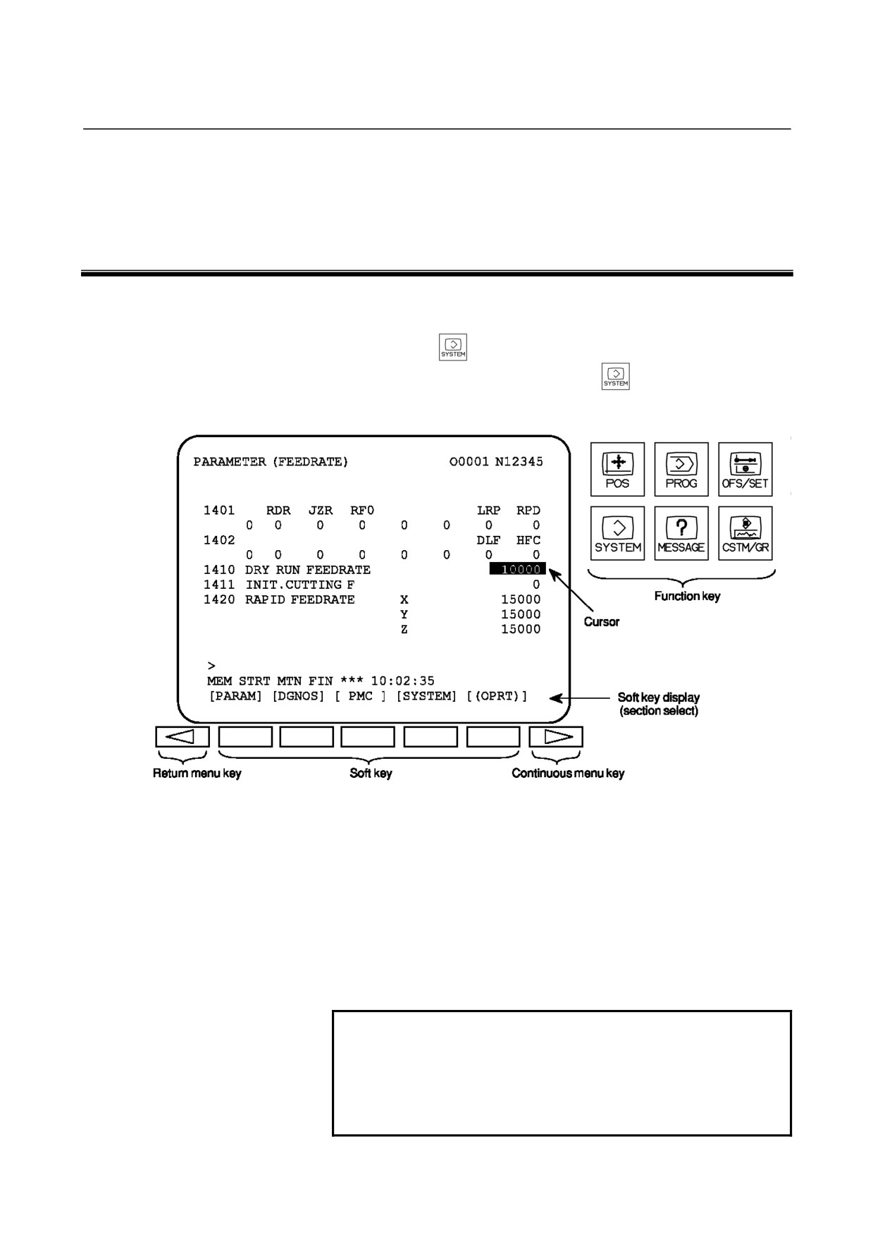
(1) Press the
function key on the MDI as many times as
required, or alternatively, press the
function key once, then
the PARAM section display soft key. The parameter screen is
then selected.
(2) The parameter screen consists of multiple pages. Use step (a) or
(b) to display the page that contains the parameter you want to
display.
(a) Use the page select key or the cursor move keys to display
the desired page.
(b) Enter the data number of the parameter you want to display
from the keyboard, then press the [NO.SRH] soft key. The
parameter page containing the specified data number
appears with the cursor positioned at the data number. (The
data is displayed in reverse video.)
NOTE
If key entry is started with the section select soft
keys displayed, they are replaced automatically by
operation select soft keys including [NO.SRH].
Pressing the [(OPRT)] soft key can also cause the
operation select keys to be displayed.
- 1 -

1.DISPLAYING PARAMETERS
B-64120EN/01
- 2 -
B-64120EN/01
2.SETTING PARAMETERS FROM MDI
2
SETTING PARAMETERS FROM MDI
Follow the procedure below to set parameters.
(1) Place the NC in the MDI mode or the emergency stop state.
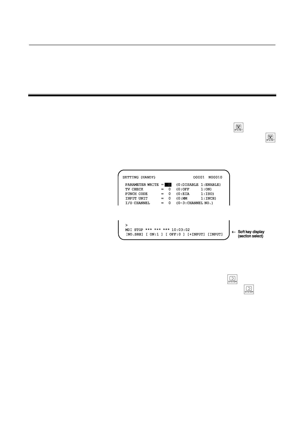
(2) Follow the substeps below to enable writing of parameters.
1.
To display the setting screen, press the
function key
as many times as required, or alternatively press the
function key once, then the [SETTING] section select soft
key. The first page of the setting screen appears.
2.
Position the cursor on "PARAMETER WRITE" using the
cursor move keys.
3.
Press the [(OPRT)] soft key to display operation select soft
keys.
4.
To set "PARAMETER WRITE=" to 1, press the ON:1 soft
key, or alternatively enter 1 and press the INPUT soft key.
From now on, the parameters can be set. At the same time
an alarm condition
(P/S100 PARAMETER WRITE
ENABLE) occurs in the CNC.
(3) To display the parameter screen, press the
function key as
many times as required, or alternatively press the
function
key once, then the PARAM section select soft key.
(See "1. Displaying Parameters.")
(4) Display the page containing the parameter you want to set, and
position the cursor on the parameter.
(See "1. Displaying
Parameters.")
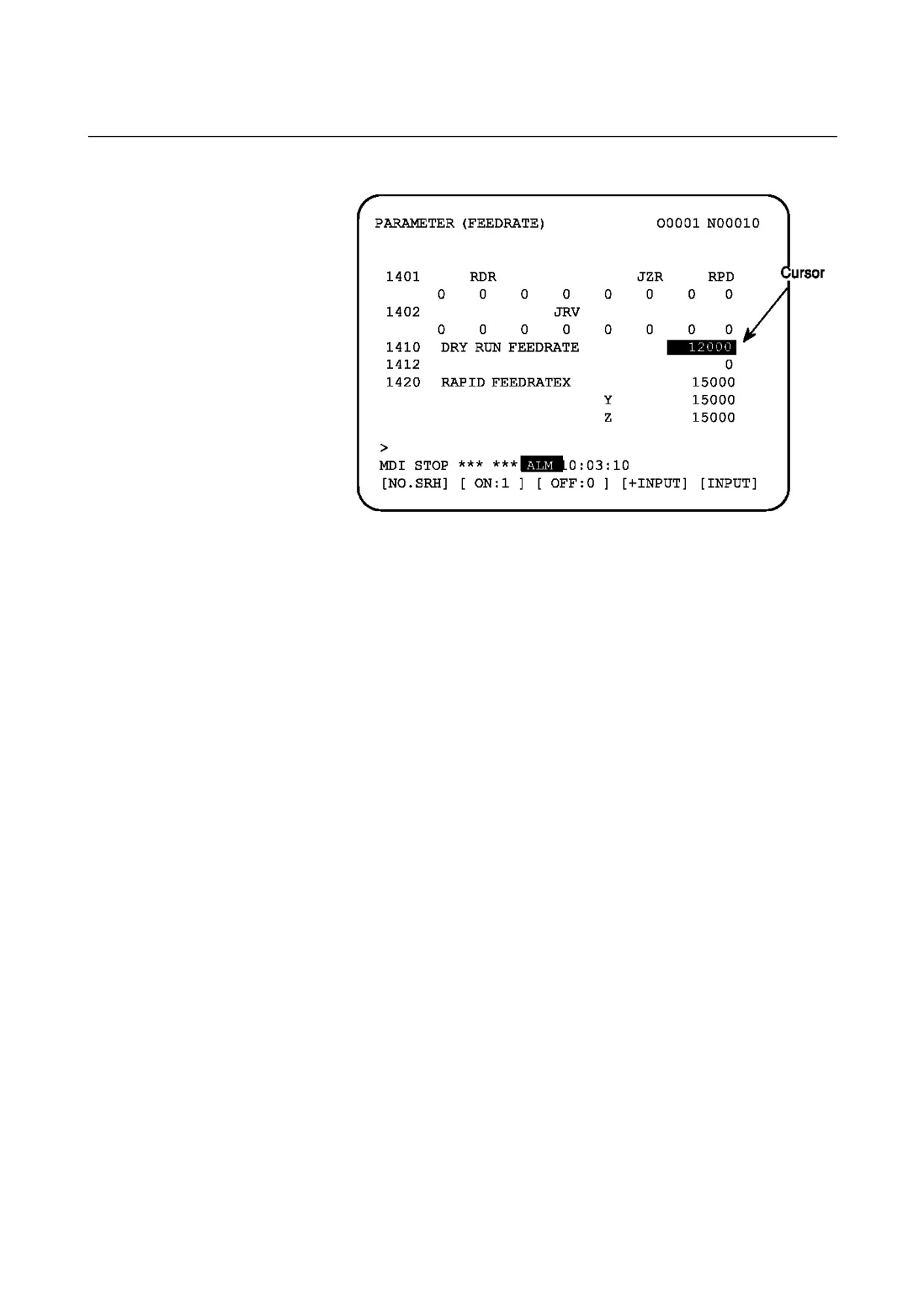
(5) Enter data, then press the [INPUT] soft key. The parameter
indicated by the cursor is set to the entered data.
- 3 -
2.SETTING PARAMETERS FROM MDI
B-64120EN/01
[Example]
12000
[INPUT]
Data can be entered continuously for parameters, starting at
the selected parameter, by separating each data item with a
semicolon (;).
[Example]
Entering 10;20;30;40 and pressing the INPUT key assigns
values 10, 20, 30, and 40 to parameters in order starting at
the parameter indicated by the cursor.
(6) Repeat steps (4) and (5) as required.
(7) If parameter setting is complete, set "PARAMETER WRITE="
to 0 on the setting screen to disable further parameter setting.
(8) Reset the NC to release the alarm condition (P/S100).
If an alarm condition (P/S000 PLEASE TURN OFF POWER)
occurs in the NC, turn it off before continuing operation.
- 4 -
B-64120EN/01
3.INPUTTING AND OUTPUTTING PARAMETERS THROUGH THE READER/PUNCHER INTERFACE
3
INPUTTING AND OUTPUTTING
PARAMETERS THROUGH THE
READER/PUNCHER INTERFACE
This section explains the parameter input/output procedures for
input/output devices connected to the reader/puncher interface.
The following description assumes the input/output devices are ready
for input/output. It also assumes parameters peculiar to the
input/output devices, such as the baud rate and the number of stop bits,
have been set in advance. (See 4.2.)
- 5 -
3.INPUTTING AND OUTPUTTING PARAMETERS THROUGH THE READER/PUNCHER INTERFACE B-64120EN/01
3.1
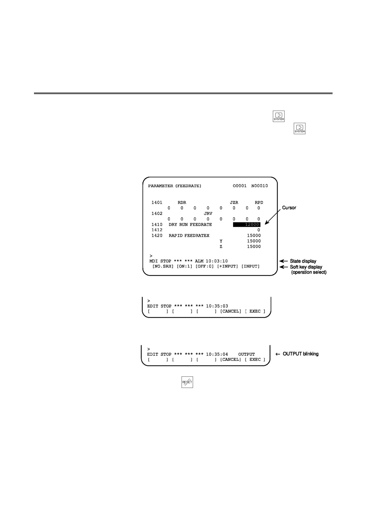
OUTPUTTING PARAMETERS THROUGH THE
READER/PUNCHER INTERFACE
(1) Select the EDIT mode or set to Emergency stop.
(2) To select the parameter screen, press the
function key as
many times as required, or alternatively press the
function
key once, then the PARAM section select soft key.
(3) Press the [(OPRT)] soft key to display operation select soft keys,
then press the forward menu key located at the right-hand side of
the soft keys to display another set of operation select keys
including [PUNCH].
(4) Pressing the [PUNCH] soft key changes the soft key display as
shown below:
(5) Press the
[EXEC] soft key to start parameter output. When
parameters are being output, "OUTPUT" blinks in the state
display field on the lower part of the screen.
(6) When parameter output terminates, "OUTPUT" stops blinking.
Press the
key to interrupt parameter output.
- 6 -
B-64120EN/01
3.INPUTTING AND OUTPUTTING PARAMETERS THROUGH THE READER/PUNCHER INTERFACE
3.2
INPUTTING PARAMETERS THROUGH THE
READER/PUNCHER INTERFACE
(1) Place the NC in the emergency stop state.
(2) Enable parameter writing.
1.
To display the setting screen, press the
function key
as many times as required, or alternatively press the
function key once, then the [SETTING] section select soft
key. The first page of the setting screen appears.
2.
Position the cursor on "PARAMETER WRITE" using the
cursor move keys.
3.
Press the [(OPRT)] soft key to display operation select soft
keys.
4.
To set "PARAMETER WRITE=" to 1, press the ON:1
soft key, or alternatively enter 1, then press the [INPUT]
soft key. From now on, parameters can be set. At the same
time an alarm condition (P/S100 PARAMETER WRITE
ENABLE) occurs in the NC.
(3) To select the parameter screen, press the
function key as
many times as required, or alternatively press the
key once,
then [PARAM] soft key.
(4) Press the [(OPRT)] soft key to display operation select keys, then
press the forward menu key located at the right-hand side of the
soft keys to display another set of operation select soft keys
including [READ].
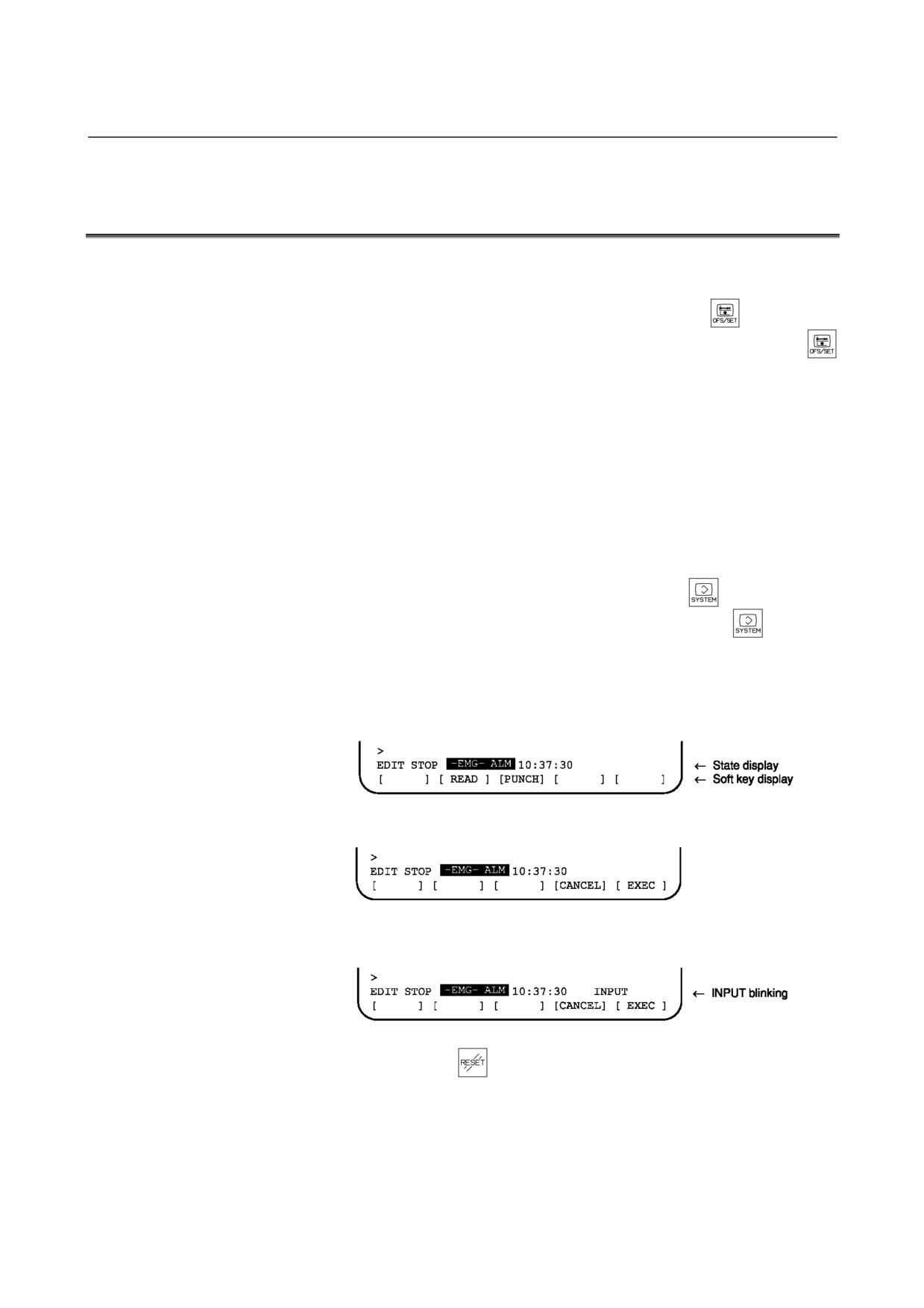
(5) Pressing the [READ] soft key changes the soft key display as
shown below:
(6) Press the [EXEC] soft key to start inputting parameters from the
input/output device. When parameters are being input, "INPUT"
blinks in the state display field on the lower part of the screen.
(7) When parameter input terminates, "INPUT" stops blinking.
Press the
key to interrupt parameter input.
(8) When parameter read terminates, "INPUT" stops blinking, and
an alarm condition (P/S000) occurs in the NC. Turn it off
before continuing operation.
- 7 -
4.DESCRIPTION OF PARAMETERS
B-64120EN/01
4
DESCRIPTION OF PARAMETERS
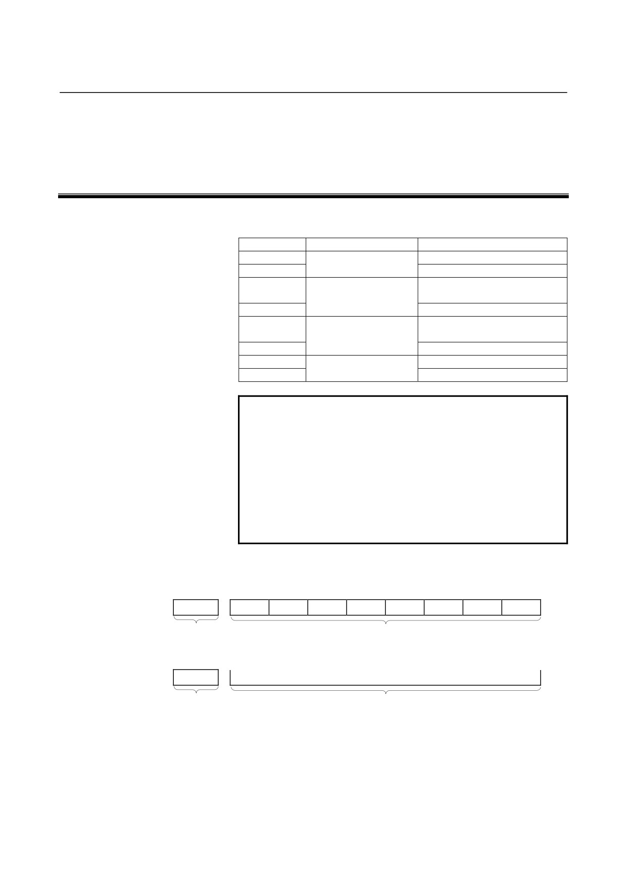
Parameters are classified by data type as follows:
Table 4 Data Types and Valid Data Ranges of Parameters
Data type
Valid data range
Remarks
Bit
0 or 1
Bit axis
In some parameters, signs are
Byte
-128 to 127
ignored.
0 to 255
Byte axis
In some parameters, signs are
Word
-32768 to 32767
ignored.
0 to 65535
Word axis
2-word
-99999999 to 99999999
2-word axis
NOTE
1 For the bit type and bit axis type parameters, a
single data number is assigned to 8 bits. Each bit
has a different meaning.
2 The axis type allows data to be set separately for
each control axis.
3 The valid data range for each data type indicates a
general range. The range varies according to the
parameters. For the valid data range of a specific
parameter, see the explanation of the parameter.
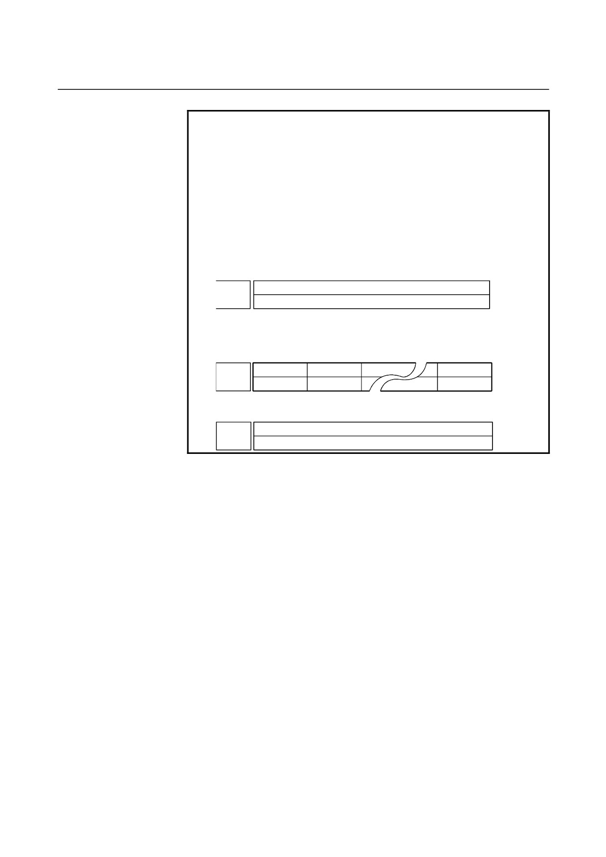
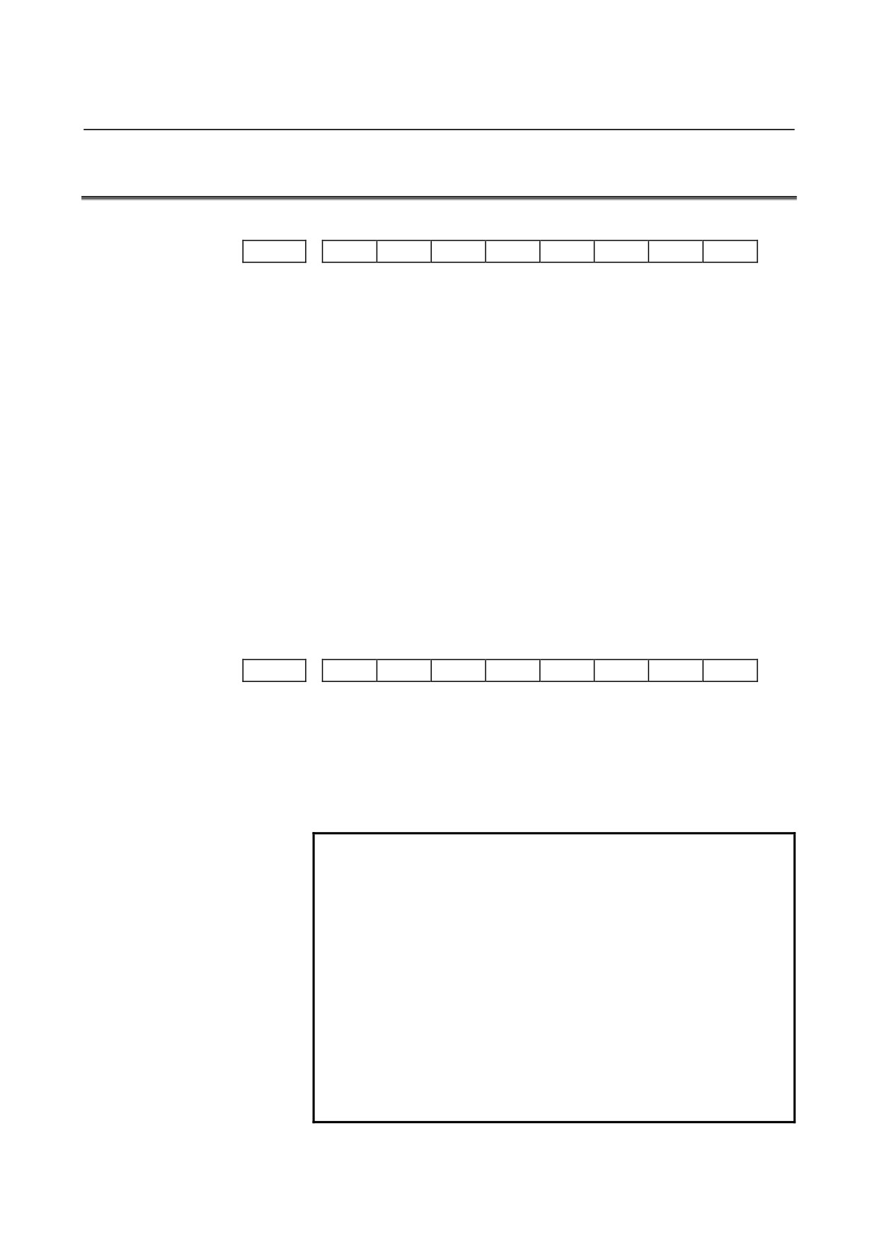
(1) Notation of bit type and bit axis type parameters
[Example]
#7
#6
#5
#4
#3
#2
#1
#0
0021
ABC
DEFGH
IJKL
TGFHJK
FGTH
FGTY
HGU
Data No.
Data #0 to #7 are bit positions.
(2) Notation of parameters other than bit type and bit axis type
0021
Servo axis number of a specific axis
Data No.
Data.
- 8 -
B-64120EN/01
4.DESCRIPTION OF PARAMETERS
NOTE
1
The bits left blank in 4. DESCRIPTION OF PARAMETERS
and parameter numbers that appear on the display but are
not found in the parameter list are reserved for future
expansion. They must always be 0.
2
Parameters having different meanings between the T
series and M series and parameters that are valid only for
the T or M series are indicated in two levels as shown
below. Parameters left blank are unavailable.
Example1
Parameter 5010 has different meanings for the T series
and M series.
Tool nose radius compensation ...
T series
5010
Tool compensation C ...
M series
Example2
DPI is a parameter common to the M and T series, but
GSB and GSC are parameters valid only for the T series.
#7
#6
#0
GSC
GSB
DPI
T series
3401
DPI
M series
Example3
The following parameter is provided only for the M series.
T series
1450
F1 digit feed ...
M series
- 9 -
4.DESCRIPTION OF PARAMETERS
B-64120EN/01
4.1
PARAMETERS OF SETTING
#7
#6
#5
#4
#3
#2
#1
#0
0000
SEQ
INI
ISO
TVC
Setting entry is acceptable.
[Data type]
Bit
TVC
TV check
0 : Not performed
1 : Performed
ISO
Code used for data output
0 : EIA code
1 : ISO code
INI
Unit of input
0 : In mm
1 : In inches
SEQ
Automatic insertion of sequence numbers
0: Not performed
1: Performed
When a program is prepared by using MDI keys in the part program
storage and edit mode, a sequence number can automatically be
assigned to each block in set increments. Set the increment
to
parameter 3216.
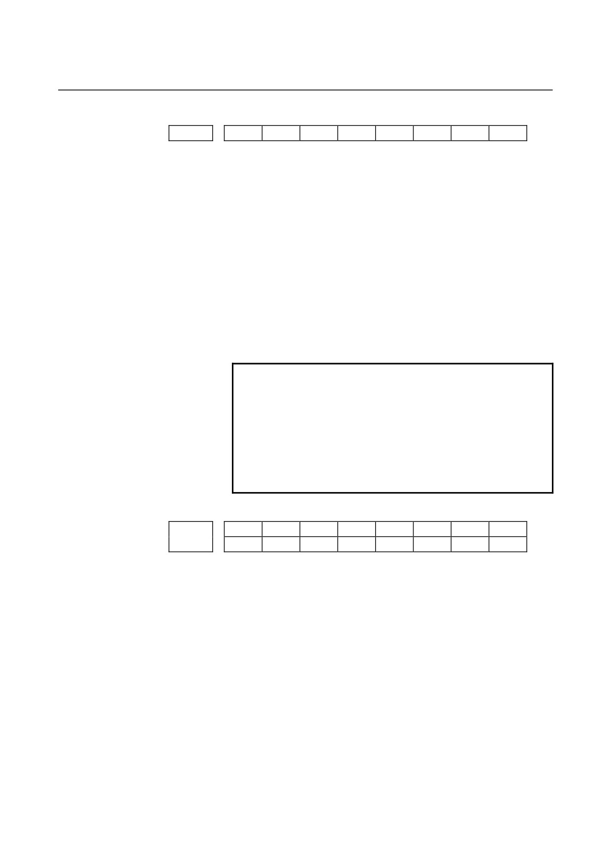
#7
#6
#5
#4
#3
#2
#1
#0
0001
FCV
Setting entry is acceptable.
[Data type]
Bit
FCV
Tape format
0: Series 0 standard format
(Series 16/18 compatible format)
1: Series 10 / 11 format
NOTE
Programs created in the Series 10 / 11 tape format
can be used for operation on the following functions:
1 Subprogram call M98
2 Thread cutting with equal leads G32 (T series)
3 Canned cycle G90, G92, G94 (T series)
4 Multiple repetitive canned cycle G71 to G76 (T
series)
5 Drilling canned cycle G73, G74, G76, G80 to G89
(M series)
6 Cutter compensation C (M series)
2 When the tape format used in the Series 10/11 is
used for this CNC, some limits may add. Refer to the
Series 0i/0i Mate-MODEL C OPERATOR'S MANUAL.
- 10 -
B-64120EN/01
4.DESCRIPTION OF PARAMETERS
#7
#6
#5
#4
#3
#2
#1
#0
0002
SJZ
RDG
Setting entry is acceptable.
[Data type]
Bit
RDG
Remote diagnosis is
0: Not performed.
1: Performed.
To use an RS-232-C serial port for performing remote diagnosis,
connect and setup the modem, cable, and the like, then set 1 in this
parameter. When using a modem card, the setting is not necessary.
SJZ
Manual reference position is performed as follows:
0 : When no reference position has been set, reference position
return is performed using deceleration dogs. When a reference
position is already set, reference position return is performed
using rapid traverse and deceleration dogs are ignored.
1 : Reference position return is performed using deceleration dogs at
all times.
NOTE
SJZ is enabled when bit 3 (HJZ) of parameter
No.1005 is set to 1. When a reference position is
set without a dog, (i.e. when bit 1 (DLZ) of
parameter No.1002 is set to 1 or bit 1 (DLZx) of
parameter No.1005 is set to 1) reference position
return after reference position setting is performed
using rapid traverse at all times, regardless of the
setting of SJZ.
#7
#6
#5
#4
#3
#2
#1
#0
RMVx
AICx
MIRx
0012
RMVx
MIRx
Setting entry is acceptable.
[Data type]
Bit axis
MIRx
Mirror image for each axis
0 : Mirror image is off.
1 : Mirror image is on.
AICx
The travel distance of an axis command is:
0: Determined by the value specified with the address.
1: Always handled as an incremental value.
- 11 -

4.DESCRIPTION OF PARAMETERS
B-64120EN/01
I/O CHANNEL: Selection of an input/output device or selection of input
0020
device in the foreground
Setting entry is acceptable.
[Data type]
Byte
[Valid data range]
0 to 35
I/O CHANNEL: Selection of the input/output device to be used
The CNC provides the following interfaces for data transfer to and
from the host computer and external input/output devices:
•
Input/output device interface (RS-232-C serial port 1, 2)
•
DNC2 interface
Data input/output can be performed with a personal computer
connected via FOCAS1/Ethernet or FOCAS1/HSSB. Data
input/output can be performed with the Power Mate CNC via the
FANUC I/O Link.
This parameter selects the interface used to transfer data to and from
an input/output device.
Setting
Description
0, 1
RS-232-C serial port 1
2
RS-232-C serial port 2
4
Memory card interface
5
Data server interface
6
The DNC operation is performed or M198 is specified by
FOCAS1/ Ethernet.
10
DNC2 interface, OSI-Ethernet
15
M198 is specified by FOCAS1/HSSB. (Bit 1 (NWD) of
parameter No. 8706) must also be specified.)
20
Group 0
21
Group 1
Data is transferred between the CNC and a
22
Group 2
power mate CNC in group n (n: 0 to 15) via the
to
to
FANUC I/O Link.
34
Group 14
35
Group 15
Supplemental remark 1
If the DNC operation is performed with FOCAS1/HSSB, the
setting of parameter No. 20 does not matter. The DMMC signal
<G042.7> is used.
Supplemental remark 2
If bit
0 (IO4) of parameter No. 110 is set to control the I/O
channels separately, the I/O channels can be divided into four
types: input and output in the foreground and input and output in
the background. If so, parameter No. 20 becomes a parameter for
selecting the input device in the foreground.
- 12 -
B-64120EN/01
4.DESCRIPTION OF PARAMETERS
NOTE
1
An input/output device can also be selected using the setting screen. Usually, the
setting screen is used.
2
The specifications (such as the baud rate and the number of stop bits) of the
input/output devices to be connected must be set in the corresponding parameters
for each interface beforehand. (See Section 4.2.) I/O CHANNEL = 0 and I/O
CHANNEL = 1 represent input/output devices connected to RS-232-C serial port 1.
Separate parameters for the baud rate, stop bits, and other specifications are
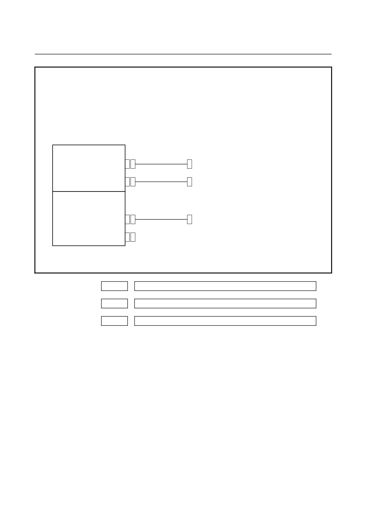
provided for each channel.
Mother board
RS-232-C serial port 1
I/O CHANNEL=0, 1
R232-1 (JD36A)
RS-232-C I/O device
(Channel 1)
RS-232-C serial port 2
R232-2 (JD36B)
I/O CHANNEL=2
RS-232-C I/O device
(Channel 2)
Serial communication board
DNC2 board
I/O CHANNEL=3
R232-3 (JD28A)
RS-232-C I/O device
(Channel 3)
(when a DNC2 board is used)
R422-1 (JD6A)
3
The input/output unit interface may be referred to as the reader/punch interface.
RS-232-C serial port 1 and RS-232-C serial port 2 are also referred to as channel 1
and channel 2, respectively.
0021
Setting of the output device in the foreground
0022
Setting of the input device in the background
0023
Setting of the output device in the background
Setting entry is acceptable.
[Data type] Byte
[Valid data range]
0 to 2, 5, 10
These parameters are valid only when bit 0 (IO4) of parameter
No. 110 is set to control the I/O channels separately.
The parameters set individual input/output devices if the I/O
channels are divided into these four types: input and output in the
foreground and input and output in the background. The input device
in the foreground is set in parameter No. 20. For the details of the
settings, see the table provided with the description of parameter No.
20.
- 13 -
4.DESCRIPTION OF PARAMETERS
B-64120EN/01
NOTE
If different input/output devices are simultaneously
used in the foreground and background, just a
value from 0 to 2 can be specified for the
background device.
If an attempt is made to use a busy input/output
device, an alarm (P/S233 or BP/S233) will be
raised. Note that the settings 0 and 1 indicate the
same input/output device.
- 14 -
B-64120EN/01
4.DESCRIPTION OF PARAMETERS
4.2
PARAMETERS OF READER/PUNCHER INTERFACE,
REMOTE BUFFER, DNC1, DNC2, AND M-NET INTERFACE
Before data (programs, parameters, and so on) can be input from and
output to an external input/output device via the input/output device
interface (RS-232-C serial port), the parameters explained below must
be set.
In the I/O CHANNEL setting parameter, the input/output device to be
used is selected by specifying one of the two channels (RS-232-C
serial port
1 and RS-232-C serial port 2) that is connected to the
input/output device.
In addition, the specifications of an input/output device connected to
each channel (such as the specification number, baud rate, and number
of stop bits of the input/output device) must be set in parameters
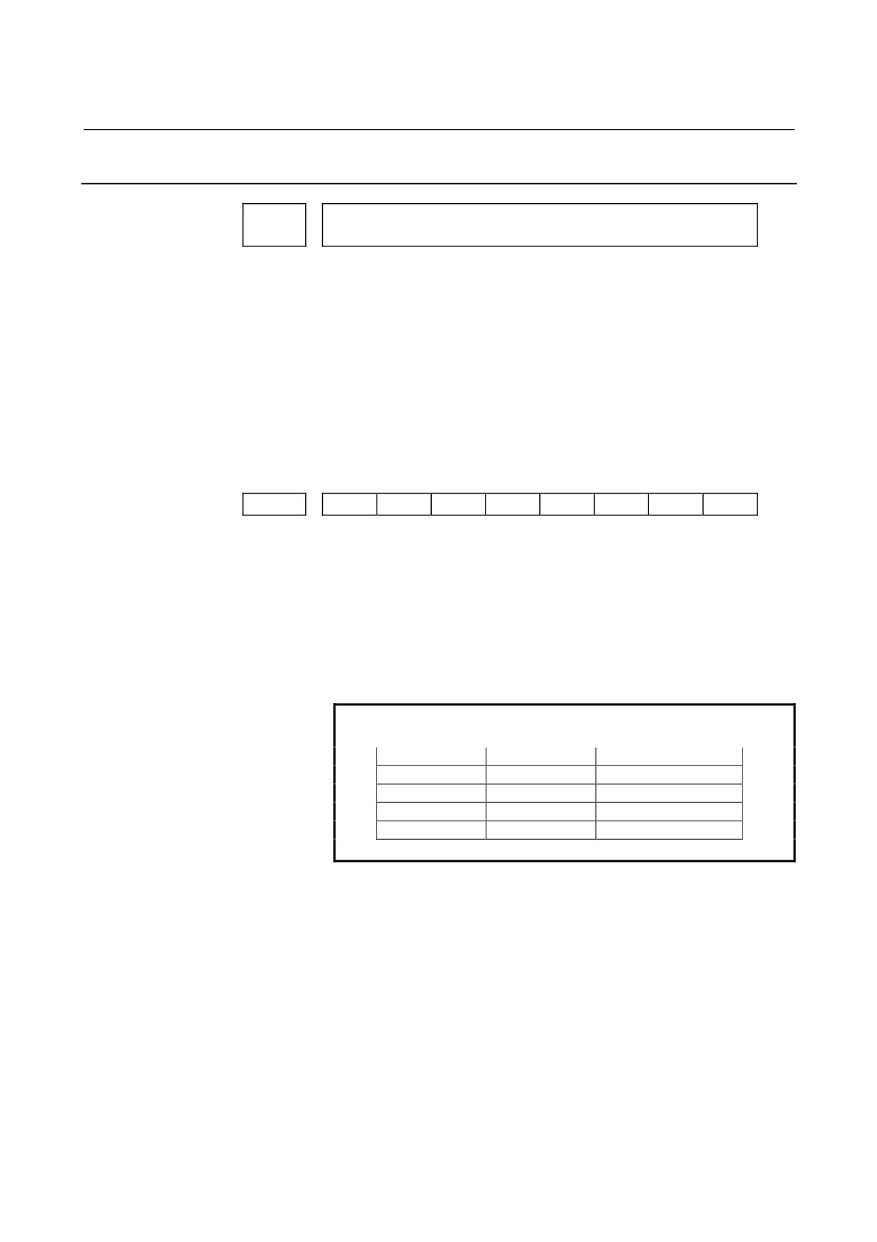
corresponding to each channel in advance.
For channel
1, two combinations of parameters to specify the
input/output device data are provided.
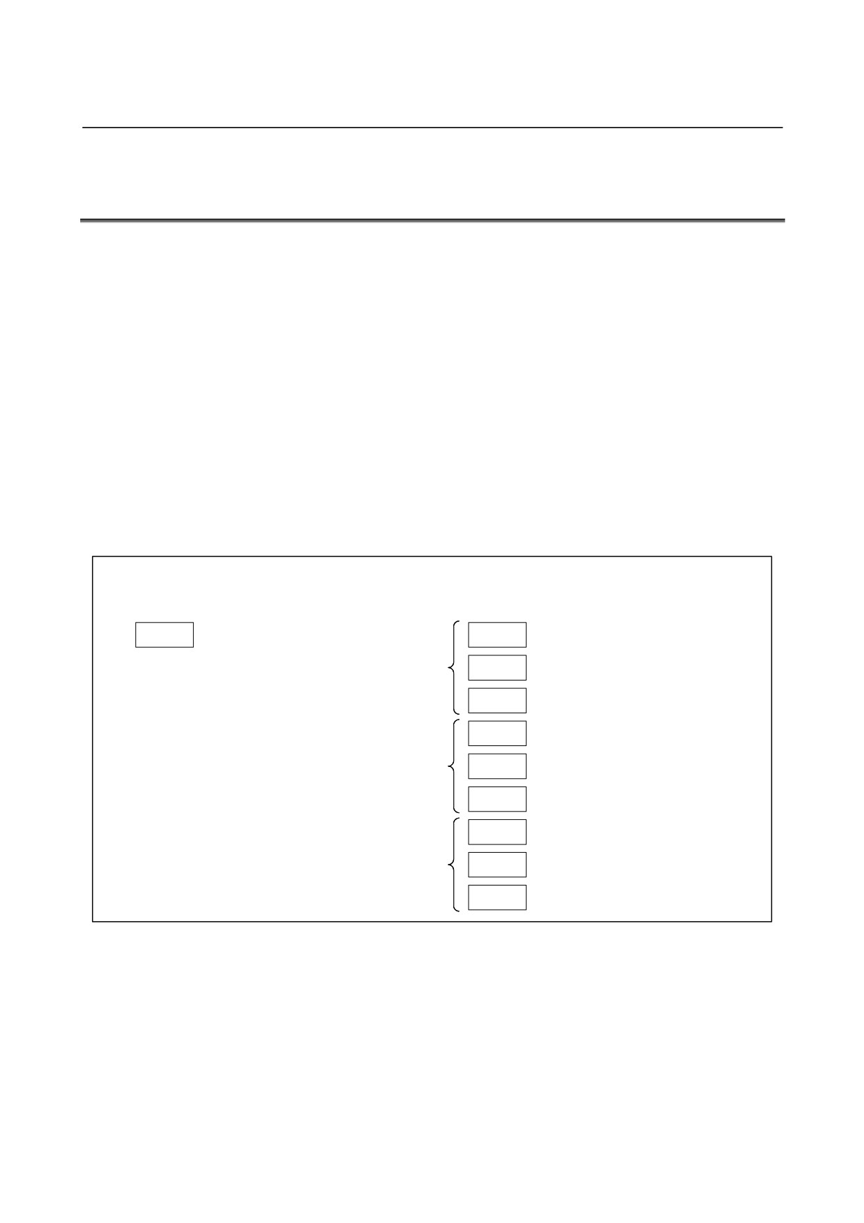
The following shows the interrelation between the input/output device
interface parameters for the channels.
Input/output channel number (parameter No.0020)
↓
0020
I/O CHANNEL
0101
Stop bit and other data
I/O CHANNEL=0
0102
Number specified for the input/output
Specify a channel for an in
(channel 1)
put/output device.
0103
Baud rate
I/O CHANNEL
=0
:
Channel1
0111
Stop bit and other data
=1
:
Channel1
=2
:
Channel2
I/O CHANNEL=1
(channel 1)
0112
Number specified for the input/output
0113
Baud rate
0121
Stop bit and other data
I/O CHANNEL=2
0122
Number specified for the input/output
(channel 2)
0123
Baud rate
Fig.4.2 I/O Device Interface Settings
- 15 -
4.DESCRIPTION OF PARAMETERS
B-64120EN/01
4.2.1
Parameters Common to all Channels
Port for communication with the PMC ladder development tool (FANUC
0024
LADDER-III)
The following parameter can be set at "Setting screen".
[Data type]
Byte
This parameter sets the port to be used for communication with the
PMC ladder development tool (FANUC LADDER-III).
0 : According to the setting on the PMC online screen
1 : RS-232-C serial port 1 (JD36A)
2 : RS-232-C serial port 2 (JD36B)
10 : High-speed interface (HSSB (COP7) or Ethernet)
11 : High-speed interface or RS-232-C serial port 1
12 : High-speed interface or RS-232-C serial port 2
#7
#6
#5
#4
#3
#2
#1
#0
0100
ENS
IOP
ND3
NCR
CRF
CTV
[Data type]
Bit
CTV:
Character counting for TV check in the comment section of
a
program.
0 : Performed
1 : Not performed
CRF
EOB (end of block) to be output in the ISO code:
0: Depends on the setting of bit 3 (NCR) of parameter No. 100.
1: is "CR""LF".
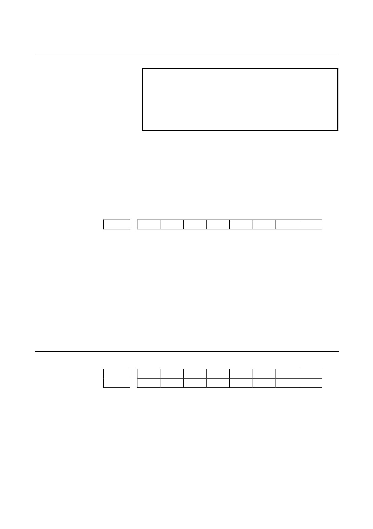
NOTE
The EOB output patterns are as shown below:
NCR
CRF
EOB output format
0
0
"LF" "CR" "CR"
0
1
"CR" "LF"
1
0
"LF"
1
1
"CR" "LF"
NCR Output of the end of block (EOB) in ISO code
0 : LF, CR, CR are output.
1 : Only LF is output.
ND3 In DNC operation, a program is:
0 : Read block by block. (A DC3 code is output for each block.)
1 : Read continuously until the buffer becomes full. (A DC3 code is
output when the buffer becomes full.)
- 16 -
B-64120EN/01
4.DESCRIPTION OF PARAMETERS
NOTE
In general, reading is performed more efficiently
when ND3 set to 1. This specification reduces the
number of buffering interruptions caused by
reading of a series of blocks specifying short
movements. This in turn reduces the effective cycle
time.
IOP
Specifies how to stop program input/output operations.
0 : An NC reset can stop program input/output operations.
1 : Only the
[STOP] soft key can stop program input/output
operations.
(An reset cannot stop program input/output
operations.)
ENS
Action taken when a NULL code is found during read of EIA code
0 : An alarm is generated.
1 : The NULL code is ignored.
#7
#6
#5
#4
#3
#2
#1
#0
0110
IO4
[Data type]
Bit
IO4
Separate control of I/O channel numbers is:
0: Not performed.
1: Performed.
If the I/O channels are not separately controlled, set the input/output
device in parameter No. 20.
If the I/O channels are separately controlled, set the input device and
output device in the foreground and the input device and output device
in the background in parameters No. 20 to No. 23 respectively.
Separate control of I/O channels makes it possible to perform
background editing, program input/output, and the like during the
DNC operation.
4.2.2
Parameters of Channel 1 (I/O CHANNEL=0)
#7
#6
#5
#4
#3
#2
#1
#0
NFD
ASI
SB2
0101
NFD
ASI
HAD
SB2
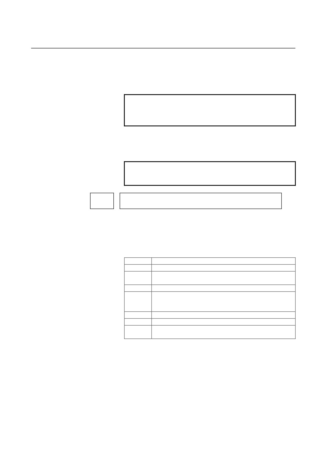
[Data type] Bit
SB2 The number of stop bits
0 :
1
1 :
2
HAD An alarm raised for the internal handy file is:
0: Not displayed in detail on the NC screen.
(PS alarm 86 is
displayed.)
1: Displayed in detail on the NC screen.
- 17 -
4.DESCRIPTION OF PARAMETERS
B-64120EN/01
ASI
Code used at data input
0 : EIA or ISO code (input: determined automatically, output:
setting of bit 1 of parameter No. 0000)
1 : ASCII code for both input and output
NOTE
When ASCII code is to be used for inputting and
outputting data (when ASI is set to 1), also set bit 1
of parameter No. 0000 to 1.
NFD
Feed before and after the data at data output
0 : Output
1 : Not output
NOTE
When input/output devices other than the FANUC
PPR are used, set NFD to 1.
Number specified for the input/output device (when the I/O CHANNEL is set
0102
to 0)
[Data type]
Byte
Set the number specified for the input/output device used when the
I/O CHANNEL is set to 0, with one of the set values listed in Table
4.2.2 (a).
Table 4.2.2 (a) Set value and Input/Output Device
Set value
Input/output device
0
RS-232-C (Used control codes DC1 to DC4)
FANUC CASSETTE ADAPTOR 1 (FANUC CASSETTE B1/
1
B2)
2
FANUC CASSETTE ADAPTOR 3 (FANUC CASSETTE F1)
FANUC PROGRAM FILE Mate, FANUC FA Card Adaptor
3
FANUC FLOPPY CASSETTE ADAPTOR, FANUC Handy File
FANUC SYSTEM P-MODEL H
4
RS-232-C (Not used control codes DC1 to DC4)
5
Portable tape reader
FANUC PPR
6
FANUC SYSTEM P-MODEL G, FANUC SYSTEM P-MODEL H
- 18 -
B-64120EN/01
4.DESCRIPTION OF PARAMETERS
0103
Baud rate (when the I/O CHANNEL is set to 0)
[Data type] Byte
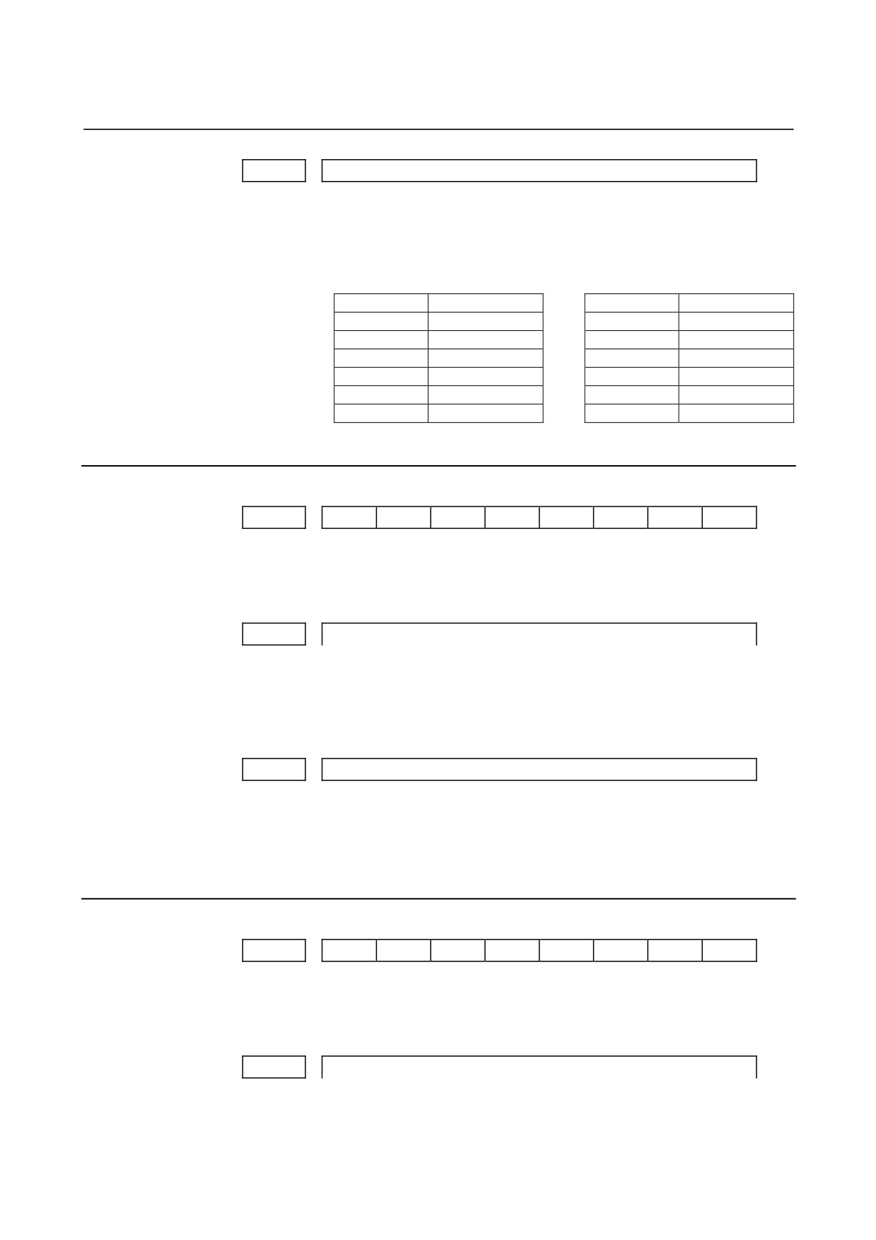
Set baud rate of the input/output device used when the I/O
CHANNEL is set to 0, with a set value in Table 4.2.2 (b).
Table 4.2.2 (b)
Set value
Baud rate (bps)
Set value
Baud rate (bps)
1
50
7
600
2
100
8
1200
3
110
9
2400
4
150
10
4800
5
200
11
9600
6
300
12
19200
4.2.3
Parameters of Channel 1 (I/O CHANNEL=1)
#7
#6
#5
#4
#3
#2
#1
#0
0111
NFD
ASI
SB2
[Data type] Bit
These parameters are used when I/O CHANNEL is set to 1. The
meanings of the bits are the same as for parameter 0101.
0112
Number specified for the input/output device (when I/O CHANNEL is set to 1)
[Data type] Byte
Set the number specified for the input/output device used when
the I/O CHANNEL is set to 1, with one of the set values listed in
Table 4.2.2 (a).
0113
Baud rate (when I/O CHNNEL is set to 1)
[Data type] Byte
Set the baud rate of the input/output device used when I/O
CHANNEL is set to 1, with a value in Table 4.2.2 (b).
4.2.4
Parameters of Channel 2 (I/O CHANNEL=2)
#7
#6
#5
#4
#3
#2
#1
#0
0121
NFD
ASI
SB2
[Data type] Bit
These parameters are used when I/O CHANNEL is set to 2. The
meanings of the bits are the same as for parameter 0101.
0122
Number specified for the input/output device (when I/O CHANNEL is set to 2)
[Data type] Byte
- 19 -
4.DESCRIPTION OF PARAMETERS
B-64120EN/01
Set the number specified for the input/output device used when I/O
CHANNEL is set to 2, with a value in Table 4.2.2 (a).
0123
Baud rate (when the I/O CHANNEL is set to 2)
[Data type]
Byte
Set the baud rate of the input/output device used when I/O
CHANNEL is set to 2, with a value in Table 4.2.2 (b).
#7
#6
#5
#4
#3
#2
#1
#0
0134
NCD
SYN
PRY
NOTE
When this parameter is set, the power must be
turned off before operation is continued.
[Data type]
Bit
PRY
Parity bit
0: Not used
1: Used
SYN
Reset/alarm in protocol B
0: Not reported to the host
1: Reported to the host with SYN and NAK codes
NCD
CD (signal quality detection) of the RS-232-C interface
0: Checked
1: Not checked
#7
#6
#5
#4
#3
#2
#1
#0
0135
RMS
PRA
ETX
ASC
NOTE
When this parameter is set, the power must be
turned off before operation is continued.
[Data type]
Bit
ASC
Communication code except NC data
0: ISO code
1: ASCII code
ETX
End code for protocol A or extended protocol A
0: CR code in ASCII/ISO
1: ETX code in ASCII/ISO
NOTE
Use of ASCII/ISO is specified by ASC.
PRA
Communication protocol
0: Protocol B
1: Protocol A
RMS
State of remote/tape operation when protocol A is used
0: Always 0 is returned.
- 20 -

B-64120EN/01
4.DESCRIPTION OF PARAMETERS
1: Contents of the change request of the remote/tape operation in
the SET command from the host is returned.
#7
#6
#5
#4
#3
#2
#1
#0
0138
MDN
OWN
[Data type] Bit
OWM When NC data or an NC program is output to a memory card, a
message for file overwrite confirmation is:
0 : Displayed.
1 : Not displayed.
MDN The DNC operation function by a memory card is:
0: Disabled.
1: Enabled. (A PCMCIA card attachment is required.)
NOTE
Use a PCMCIA card attachment suited to the CNC
to secure the memory card in the CNC.
- 21 -