FANUC Series 90-30 PLC. Installation and Hardware Manual (GFK-0356Q) - page 5
5
Additional Serial Ports (CPU351, CPU352, CPU363)
Although all Series 90-30 CPUs have a serial port that is accessed through the connector on the
power supply, the CPU351, CPU352, and CPU363 each have two additional serial ports. The
connectors for these additional serial ports are mounted on the front of each CPU. These two built-
in serial ports eliminate the need for the CPU to access serial ports across the PLC backplane,
resulting in better system performance. These two ports support the SNP/SNP-X master and slave
protocols (see “Breakfree SNP Protocol” on page 5-13.), RTU slave protocol (in Firmware Version
8.0 and later), and the Serial I/O feature (in Firmware Version 8.0 and later) that lets you create a
custom serial output. Instructions on how to use these ports can be found in the Series 90 PLC
Serial Communications User’s Manual, GFK-0582C or later.
Floating-Point Math
All Series 90-30 CPUs can work with integer numbers. (The set of integer numbers consists of all
positive and negative whole numbers, including zero.) The floating-point math feature enables a
CPU to work with decimal numbers in addition to integer numbers. It also provides trigonometric,
logarithmic, exponential, and radian conversion functions. Floating-point math is also referred to as
“real number” math. The CPU352 and CPU374 have always had hardware-based floating-point
math capabilities due to the built-in math co-processor chip. Starting with CPU firmware release
9.0, all of the other CPUs in the 350-364 CPU group were provided with firmware-based floating-
point math capability. Although there is a speed difference between the hardware-based floating-
point math of the CPU352 and CPU374 and the firmware-based type, this will not be significant to
many users. For applications where faster performance is important, the CPU352 and CPU374 are
the best choice. The floating-point math instructions are explained in the Series 90-30 PLC CPU
Instruction Set Reference Manual, GFK-0467K or later.
Flash Memory
All of the 350-374 CPUs have built-in Flash memory, which serves two purposes:
■ It provides non-volatile storage of the CPU firmware.
■ It gives you the option of storing program, configuration, and register data in non-volatile
Flash memory. Two ways of using this memory are: (1) to store an on-board backup copy of
user memory (although we still recommend that you keep a separate backup copy of your
complete program folder), and (2) for running in a battery-less scheme. For details, please see
Chapter 6.
Keyswitch
All 350 - 374 CPUs have a keyswitch; however, some versions of the CPU firmware do not
support all of the keyswitch features (see the section “Determining CPU Revision Levels” earlier in
this chapter). These differences are described in this section. Note that the keyswitches on some of
these CPUs are labeled ON/RUN and OFF/STOP and on others are just labeled ON and OFF.
Regardless of the labeling, all of these keyswitches work as described below:
■ Flash Memory Protection: This standard, hard-wired feature can be used to prevent Flash
memory from being changed by unauthorized people (people without a key). When the key
switch is in the ON position, Flash memory cannot be changed (written to). This keyswitch
feature will always be in effect, regardless of how the next two configurable features are set.
GFK-0356Q
Chapter 5 CPUs
5-15
5
■ Run/Stop (configurable): This feature was introduced in CPU firmware release 7.0. It is, by
default, disabled. It is not functional unless the R/S Switch: parameter on the CPU
configuration screen is set to Enabled. This feature, when enabled, lets you stop the PLC by
turning the key switch to OFF, or start the PLC running by turning the key switch to ON (if
there are no faults).
If the PLC has a non-fatal fault, turning the key switch from OFF to ON will cause the RUN
light on the power supply to flash for 5 seconds. If you again turn the key switch OFF, then
ON during the 5 seconds, the fault will clear and the PLC will go into run mode (and the RUN
light will stay ON).
If the PLC has a fatal fault, you will not be able to use the keyswitch to either clear the fault
or put the PLC into run mode. You will have to correct the cause of the fault before being able
to resume operation.
■ RAM Memory and Override Protection (configurable): This feature was introduced in
CPU firmware release 8.0. This feature is, by default, disabled. It is not functional unless the
Mem Protect: parameter on the CPU configuration screen is set to Enabled. If this feature is
enabled and the keyswitch is ON, (1) user RAM memory cannot be changed (2) discrete points
cannot be overridden, and (3) the TOD clock cannot be changed with the Hand Held
Programmer (however, the TOD clock can still be changed using programming software).
Protect your keys. Each new 350-374 CPU is supplied with a pair of keys for the key switch. If
you use one or more of the key switch protection features described above, we recommend you
carefully guard your keys. If they are lost, misplaced, or stolen, you may be locked out from
working on your PLC, and unauthorized persons may have access to it. Replacement keys can be
purchased under part number 44A736756-G01. This kit contains three sets of CPU keys. All 350-
374 CPUs use the same key.
Of course, you can choose to not use any of the keyswitch protection features, in which case you
can leave the keyswitch set to the OFF position, and leave the two configurable keyswitch features
set at their default (disabled) settings. Then, you will not need to use a key to access the PLC.
Sequential Event Recorder (SER) Instruction
This functional instruction (programmed in ladder logic) was introduced in CPU firmware release
9.0 and is available in all of the 350 - 374 CPUs that have this firmware. The purpose of the SER
is to provide a dynamic troubleshooting and debugging tool. In effect, it takes ”snapshots” of the
on/off status of groups of discrete points that you specify. You also specify how many of these
snapshots to take, when and how often they will be taken, and where in memory they will be
stored. The stored snapshots can be analyzed to see the time relationship of the bits sampled.
Please see the Series 90-30 PLC CPU Instruction Set Reference Manual, GFK-0467K or later for
details on using this instruction. Some feature highlights:
■ An SER function block collects up to 32 contiguous or non-contiguous bits per sample.
■ Each SER function block can capture up to 1024 samples.
■ If the SER is embedded in a periodic subroutine, sampling rate is determined by the periodic
subroutine execution rate.
■ Only the trigger sample is time stamped. The trigger sample can be time-stamped in BCD
(maximum resolution of 1 s) or POSIX format (maximum resolution of 10ms). The time
5-16
Series 90-30 PLC Installation and Hardware Manual - August 2002
GFK-0356Q
5
stamp is only placed once at the trigger point. The SER does not support more than one time
stamp per recording.
■ The SER can be configured for pre-, mid-, or post-trigger modes.
Embedded Ethernet Interface (CPU364 and CPU374)
The CPU364 and CPU374 consist of a CPU and an Ethernet Interface combined in one module.
These modules offer Ethernet capabilities formerly available only with the separate
IC693CMM321 Ethernet module. The CPU364 and CPU374 offer several advantages compared
to using a separate CPU and Ethernet module:
■
It only occupies one slot in the PLC baseplate compared to the two slots required by separate
CPU and Ethernet modules.
■
The CPU374 has two 10/100 BASE-T/TX ports connected to an embedded network switch.
■
The IC693CMM321 Ethernet module requires an external transceiver. The CPU364 does not
require one since it has this functionality built-in. To use this internal transceiver, connect to
the 10BASE-T port. However, if you choose, you may use an external transceiver by
connecting to the CPU364’s AAUI port, which bypasses the internal transceiver (see
Appendix J for GE Fanuc transceiver information).
■
The CPU374 does not require an external transceiver for either of its 10/100 BASE T/TX
ports.
■
Because they both reside in the CPU module, the CPU and Ethernet Interface can
communicate without using the PLC backplane. This provides faster communications speed
compared to using separate CPU and Ethernet modules, which have to use the slower path
across the PLC backplane.
■
Beginning with Firmware Release 9.1, the Ethernet Global Data (EGD) and configurable
Name Resolution features were added to the CPU364. The CPU374 supports EGD, but not
Name Resolution. These features are not supported by the IC693CMM321 Ethernet module.
Logicmaster software does not support these features. They are supported only in Control,
Version 2.2 or later, all versions of VersaPro software, and CIMPLICITY Machine Edition
software Logic Developer-PLC. For details about these features, please see publication GFK-
1541A or later, TCP/IP Ethernet Communications for the Series 90 PLC User’s Manual.
GFK-0356Q
Chapter 5 CPUs
5-17
5
Hardware Features of the 350-364 CPUs
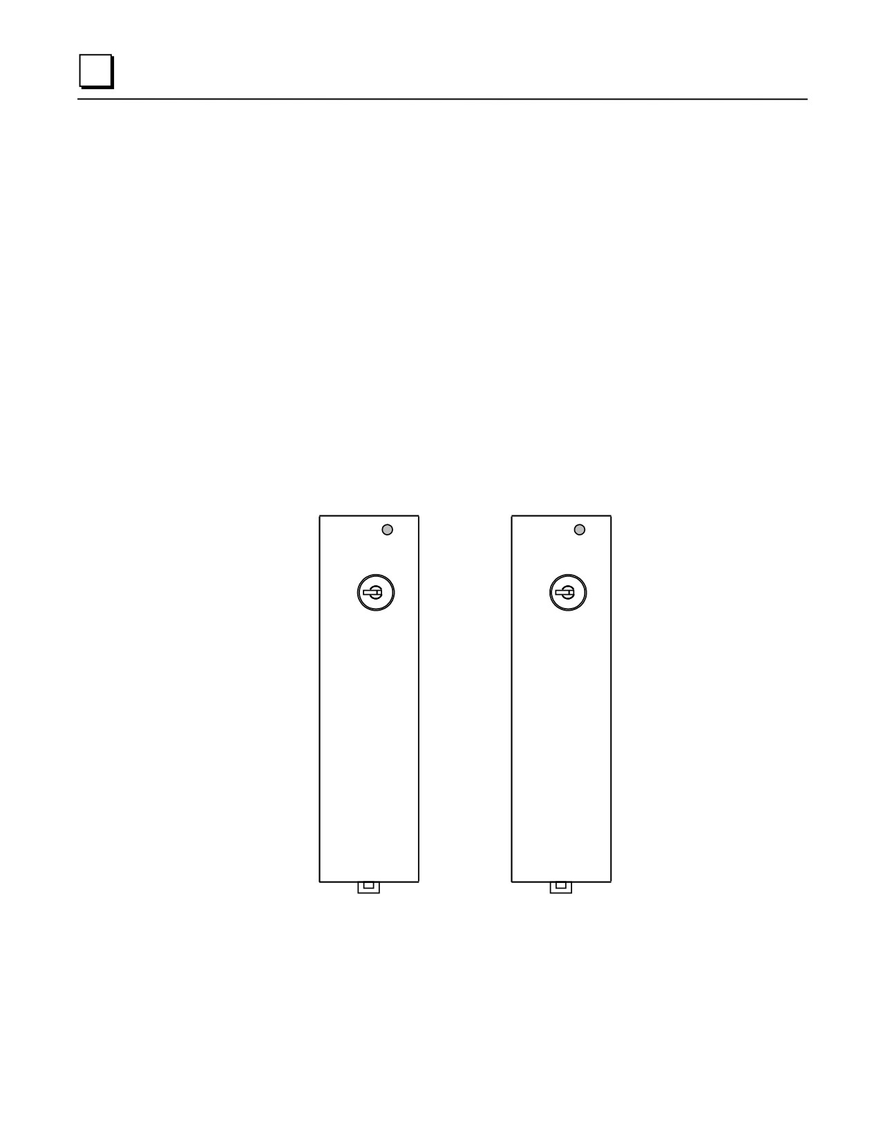
CPU350 and CPU360 Hardware Features
These two modules look identical except for labeling.
■ These modules feature an LED light, labeled “PS Port” that indicates serial port activity
through the serial connector on the PLC power supply. Typically, this LED will flash while
data is being transferred through the port, and will stay off when the port is inactive.
■ These modules also have the keyswitch, described earlier in this chapter, that is standard on the
350-364 CPUs.
CPU Firmware Upgrade
The CPU firmware, which is stored in Flash memory, is loaded through the serial port connector on
the PLC Power Supply.
PS
PS
PORT
PORT
CPU 350
CPU 360
ON
ON
OFF
OFF
5-18
Series 90-30 PLC Installation and Hardware Manual - August 2002
GFK-0356Q
5
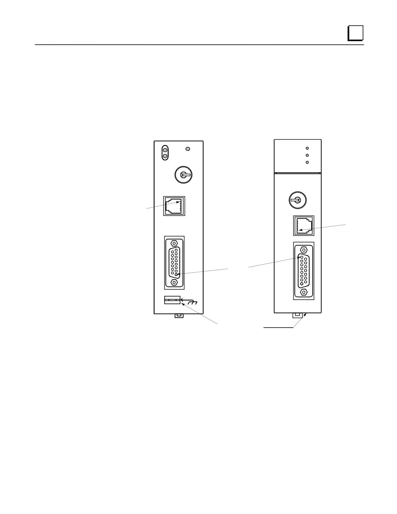
CPU351, CPU352, and CPU363 Hardware Features
These three modules are similar in features and functionality. The CPU351 and CPU352 look
identical except for labeling. The CPU363 has the same features as the other two, but the
orientation of its Port 1 and Port 2 connectors is reversed from those of the CPU351 and CPU352,
and its LED indicator lights, key switch, and shield ground connector are in different locations.
(The shield ground connector is on the front panel of the CPU363, labeled “FRAME,” but is
located on the bottom of the CPU351 and CPU352 modules.)
PS
CPU 351
SNP
P1
PORT
P1
P2
CPU 363
P2
ON
OFF
ON/RUN
OFF/
PORT 1
STOP
RS-232
PIN 1
PORT 1
PIN 1
RS-232
PORT 2
RS-485
PIN 1
PORT 2
RS-485
FRAME
Shield Ground
Connector
Figure 5-4. CPUs 351, 352, and 363
CPU Firmware Upgrade
The CPU firmware, which is stored in Flash memory, is loaded through the Port 1 connector on
these modules’ faceplate using Loader software supplied with the firmware upgrade kit. The
IC693CBL316 cable can be used for this purpose (see Chapter 10 for data sheet on this cable).
Keyswitch
This is a standard CPU keyswitch, discussed earlier in this chapter.
GFK-0356Q
Chapter 5 CPUs
5-19
5
Shield Ground Connection Tab
This tab is located on the bottom of the CPU351 and 352 modules and on the front of the CPU363
module. It is used to make the module’s shield ground connection. A wire with the applicable
terminal ends is supplied with the module for this purpose. Please see the section ”Module Shield
Grounding” in Chapter 2 (“Installation”) for details.
Serial Ports
The 351, 352, and 363 CPUs have three serial ports. One is accessed through a connector on the
PLC power supply (standard serial port found on all Series 90-30 CPUs), and the connectors for the
other two are on the modules’ front panel, labeled Port 1 and Port 2.
The CPU351, 352, and 363 serial ports are configurable using the programming software
configuration function. Each port can also be configured using a COMM_REQ. For details about
using these ports and about the COMM_REQ instruction, please see publication GFK-0582, Series
90 PLC Serial Communications User’s Manual.
Serial Port Front Panel Connectors
■ Port 1, the top port is RS-232 compatible. This port has a 6-pin RJ-11 connector. This
connector has female contacts and is similar to modular jacks commonly used for telephones
and modems. The IC693CBL316 can be used to access this port, providing a direct connection
to an RS-232 device without the need for a converter. See Chapter 10 for a datasheet on this
cable.
■ Port 2, the bottom port is RS-485 compatible. Access to Port 2 is through a 15-pin D
connector that has female contacts.
Serial Port Status LEDs
The CPU351 and CPU352 have three LEDs that indicate the status of serial port activity on the
CPU.
■ The SNP LED on the CPU351 and CPU352 is called PS Port on the CPU363. This refers to
the port that uses the serial connector on the PLC’s power supply. This LED flashes when data
is being transferred through the port. It remains off when the port is inactive.
■ The P1 LED will flash when data is being transferred through Port 1, the RS-232 port. It
remains off when the port is inactive.
■ The P2 LED will flash when data is being transferred through Port 2, the RS-485 port. It
remains off when the port is inactive.
5-20
Series 90-30 PLC Installation and Hardware Manual - August 2002
GFK-0356Q
5
Protocols Supported
Starting with Firmware Release 9.00, breakfree SNP became the default protocol on the three
Serial Ports on these modules. See “Breakfree SNP Protocol” on page 5-13 for details.
SNP Port (Through Power Supply Connector)
■ SNP slave
■ SNP-X slave
Port 1 and Port 2 (Through Module’s Front Panel Connectors)
■ SNP master and slave
■ SNP-X master and slave
■ RTU slave (starting with Firmware Release 8.0)
■ Serial I/O - Limited functionality (write only) starting with Firmware Release 8.0, will have
full functionality (read and write) starting with Firmware Release 10.0. Used with autodialer
feature to call a pager. To use this feature, configure protocol as Custom. See GFK-0582,
Series 90 PLC Serial Communications User’s Manual for details.
GFK-0356Q
Chapter 5 CPUs
5-21
5
Pin Assignments for CPU351, CPU352, and CPU363 Serial Ports 1 & 2
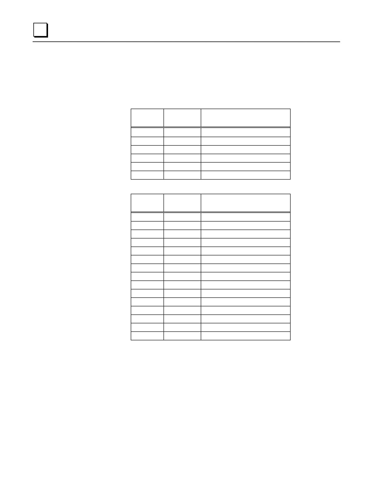
The following two tables describe the pin assignments for each of the two front panel serial ports
on the CPU351, CPU352, and CPU363.
Table 5-6. Port 1 (RS-232)
Pin
Signal
Number
Name
Description
1
CTS
Clear To Send
2
TXD
Transmit Data
3
0V
Signal Ground
4
0V
Signal Ground
5
RXD
Receive Data
6
RTS
Request to Send
Table 5-7. Port 2 (RS-485)
Pin
Signal
Number
Name
Description
1
Shield
Cable Shield
2
NC
No Connection
3
NC
No Connection
4
NC
No Connection
5
+5VDC
Logic Power *
6
RTS(A)
Differential Request to Send
7
SG
Signal Ground
8
CTS(B‘)
Differential Clear To Send
9
RT
Resistor Termination
10
RD(A‘)
Differential Receive Data
11
RD(B‘)
Differential Receive Data
12
SD(A)
Differential Send Data
13
SD(B)
Differential Send Data
14
RTS(B’)
Differential Request To Send
15
CTS(A’)
Differential Clear To Send
* Note that Pin 5 provides Isolated +5 VDC power (100 mA maximum) for
powering external options.
5-22
Series 90-30 PLC Installation and Hardware Manual - August 2002
GFK-0356Q
5
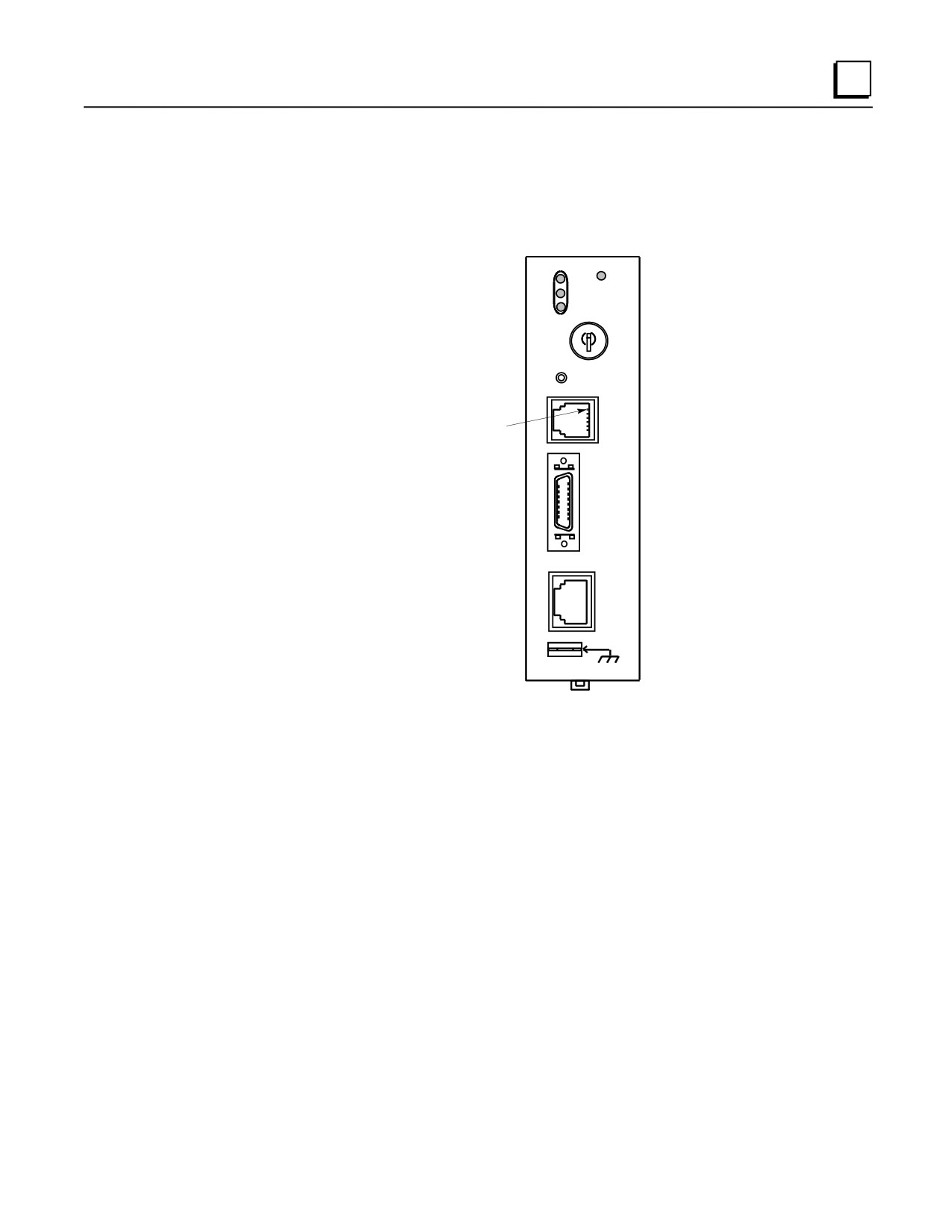
CPU364 Hardware Features
This module has four LED indicator lights, an Ethernet Restart pushbutton, a standard CPU
keyswitch, three port connectors, and a shield ground connection tab (labeled “FRAME”).
PS
EOK
PORT
LAN
CPU 364
STAT
ON
OFF
ETHERNET
RESTART
PORT 1
RS-232
PIN 1
AAUI
10BASE T
FRAME
LED Indicators
There are four LED Indicators. Three relate to the Ethernet interface: EOK, LAN, and STAT.
These can be ON, OFF, FLASHING slow, or FLASHING fast in several different combinations.
The full functionality of these LEDs is detailed in GFK-1541, TCP/IP Ethernet Communications
for the Series 90 PLC User’s Manual.
The fourth LED, PS PORT, is for the CPU’s serial port and is not related to the Ethernet interface.
This LED will flash while data is being transferred through the SNP serial port connector on the
PLC power supply, and will stay off when the port is inactive. (On some early production 364
CPUs, this LED is labeled “SNP.”) All Series 90-30 CPUs have this standard serial port.
Ethernet Restart Pushbutton
This pushbutton performs four functions: LED test, Restart, Restart and enter Software Load state,
and Restart and enter Maintenance state. These are detailed in GFK-1541, TCP/IP Ethernet
Communications for the Series 90 PLC User’s Manual.
GFK-0356Q
Chapter 5 CPUs
5-23
5
Keyswitch
This is a standard CPU keyswitch, discussed earlier in this chapter.
Front Panel Connectors
The full functionality of these ports is detailed in GFK-1541, TCP/IP Ethernet Communications for
the Series 90 PLC User’s Manual.
■ Port 1, RS-232 - This connector is used for two purposes: (1) To connect a terminal or
terminal emulator to access the Station Manager software on the Ethernet Interface. (2) To
connect to a Personal Computer that will be used to update the Ethernet Interface firmware
(the CPU firmware is updated separately through the connector on the power supply). This
RJ-11 connector has the same pinout as Port 1 of the CPUs 351, 352, and 353, shown in Table
5-5. The IC693CBL316 cable can be used to access this port. See Chapter 10 for a data sheet
on this cable.
■ AAUI port - This 14-pin AAUI port connects via a user-supplied IEEE 802.3 transceiver
cable to an external Ethernet-compatible transceiver such as the GE Fanuc catalog number
IC649AEA102 (for 10Base T) or IC649AEA103 (for 10Base 2). See Appendix J for details on
these transceivers.
■
10Base T port - This 8-pin, RJ-45 port provides a direct connection to a 10Base T (twisted
pair) Ethernet network without the need for an external transceiver.
Shield Ground Connection Tab
This tab is used to make the module’s shield ground connection. A wire with the applicable
terminal ends is supplied with the module for this purpose. Please see the section “CPU363 and
364 Shield Grounding” in Chapter 2 (“Installation”) for details.
Firmware Upgrade
■ The CPU firmware, which is stored in Flash memory, is loaded through the serial port
connector on the PLC Power Supply using a personal computer that has been equipped with
the loader and CPU firmware software.
■ The Ethernet Interface firmware, stored in Flash memory, is loaded through the module’s front
panel Port 1 connector using a personal computer that has been equipped with the loader and
Ethernet firmware software. Cable IC693CBL316 is required (see Chapter 10 for details on
this cable).
5-24
Series 90-30 PLC Installation and Hardware Manual - August 2002
GFK-0356Q
5
CPU374 Hardware Features
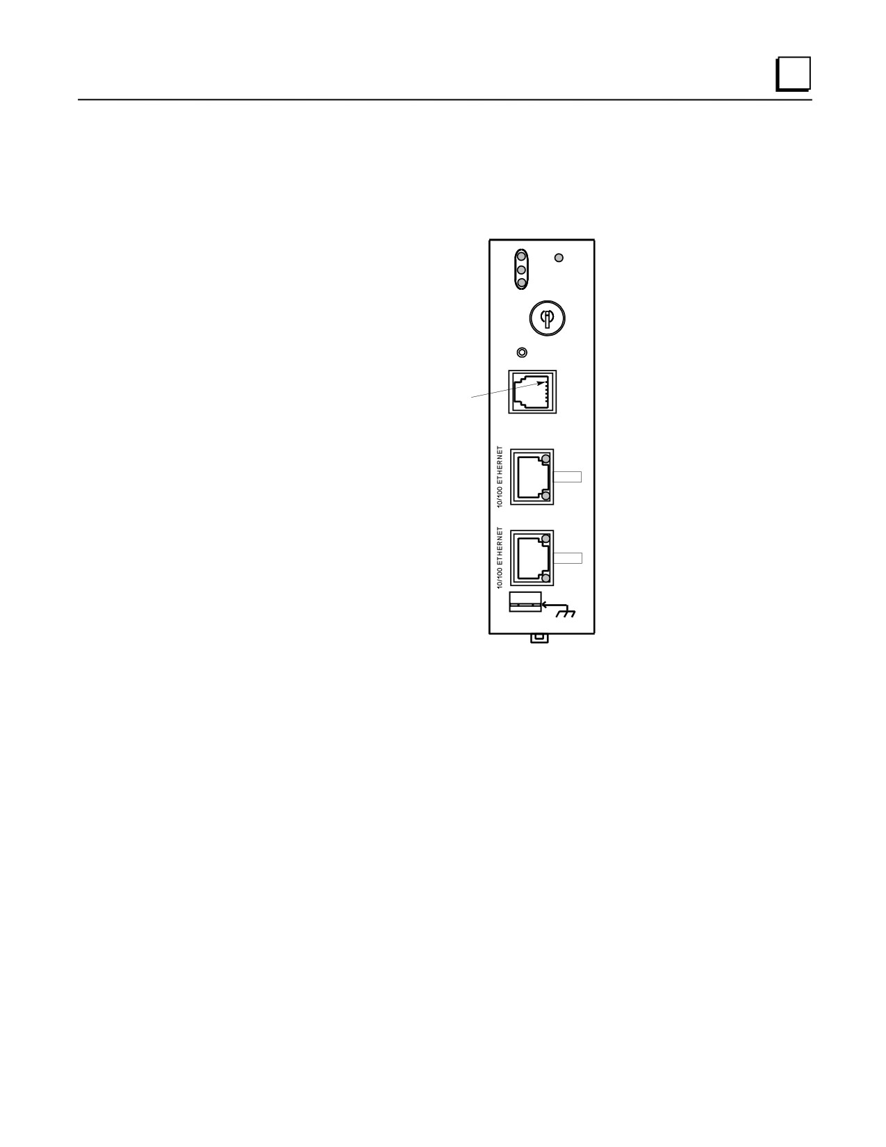
This module has eight LED indicators, an Ethernet Restart pushbutton, a standard CPU keyswitch,
three port connectors, and a shield ground connection tab (labeled “FRAME”).
PS
EOK
PORT
LAN
STAT
CPU 374
ON
OFF
ETHERNET
RESTART
STATION
MGR
PIN 1
LINK/ACT
PORT 1
100Mbps
LINK/ACT
PORT 2
100Mbps
FRAME
LED Indicators
There are four LED Indicators. Three relate to the Ethernet interface: EOK, LAN, and STAT.
These can be ON, OFF, FLASHING slow, or FLASHING fast in several different combinations.
The full functionality of these LEDs is detailed in GFK-1541, TCP/IP Ethernet Communications
for the Series 90 PLC User’s Manual.
The fourth LED, PS PORT, is for the CPU’s serial port and is not related to the Ethernet interface.
This LED will flash while data is being transferred through the SNP serial port connector on the
PLC power supply, and will stay off when the port is inactive. All Series 90-30 CPUs have this
standard serial port.
Ethernet Restart Pushbutton
This pushbutton performs four functions: LED test, Restart, Restart and enter Software Load state,
and Restart and enter Maintenance state. These are detailed in GFK-1541, TCP/IP Ethernet
Communications for the Series 90 PLC User’s Manual.
GFK-0356Q
Chapter 5 CPUs
5-25
5
Keyswitch
This is a standard CPU keyswitch, discussed on page 3-15.
Front Panel Connectors
The full functionality of these ports is detailed in GFK-1541, TCP/IP Ethernet Communications for
the Series 90 PLC User’s Manual.
■ Station Mgr - This connector is used to connect a terminal or terminal emulator to access the
Station Manager software on the Ethernet Interface. This RJ-11 connector has the same pinout
as Port 1 of the CPUs 351, 352, 353, and 364 shown in Table 5-5. The IC693CBL316 cable
can be used to access this port. See Chapter 10 for a data sheet on this cable.
■
10/100 Ethernet (Port 1 and Port 2) - these two 8-pin, RJ-45 ports provide a direct
connection to an Ethernet network via an embedded network switch.
The two Ethernet ports are 10-BASE-T/100-BASE-Tx Autonegotiating Full-Duplex ports,
which provide direct connection to one or two 10-BASE-T/100-BASE-TX cat 5 (twisted pair)
Ethernet LAN cables. Cables may be shielded or unshielded, and direct or cross-over. Please
note that the ports are connected to an embedded switch. There is not a separate IP address for
each port.
The LINK/ACT LED on each port goes on when a network link is established and blinks when
data is being transferred through the port. The 100Mbps LED goes on if the network link has
been established at 100 MBPS and goes off if the network link has been established at
10Mbps.
Shield Ground Connection Tab
This tab is used to make the module’s shield ground connection. A wire with the applicable
terminal ends is supplied with the module for this purpose. Please see the section “CPU363, 364,
and 374 Shield Grounding” in Chapter 2 (“Installation”) for details.
Firmware Upgrade
■ The CPU and Ethernet Interface firmware, which is stored in Flash memory, is loaded through
the serial port connector on the PLC Power Supply using a personal computer that has been
equipped with the loader and CPU firmware software.
5-26
Series 90-30 PLC Installation and Hardware Manual - August 2002
GFK-0356Q
5
CPU Data Sheets
This section provides data sheets describing each of the Series 90-30 CPU modules. For
information on the State Logic CPUs, see Chapter 9, “State Logic Products.”
CPU Model List
■ IC693CPU311
5-slot baseplate with embedded CPU, 1K Byte Register Memory
■ IC693CPU313
5-slot baseplate with embedded CPU, 2K Bytes Register Memory
■ IC693CPU323
10-slot baseplate with embedded CPU
■ IC693CPU331
CPU module, 10 MHz
■ IC693CPU340
CPU module, 20 MHz, 32K Bytes User Program Memory
■ IC693CPU341
CPU module, 20 MHz, 80K Bytes User Program Memory
■ IC693CPU350
CPU module, 25 MHz
■ IC693CPU351
CPU module, 25 MHz, with two extra serial ports
■ IC693CPU352
CPU module, 25 MHz, math coprocessor, two extra serial ports
■ IC693CPU360
CPU module, 25 MHz
■ IC693CPU363
CPU module, 25 MHz, with two extra serial ports
■ IC693CPU364
CPU module, 25 MHz, with Ethernet interface
■ IC693CPU374
CPU module, 133 MHz, 240K bytes User Program Memory with
Ethernet communications
GFK-0356Q
Chapter 5 CPUs
5-27
5
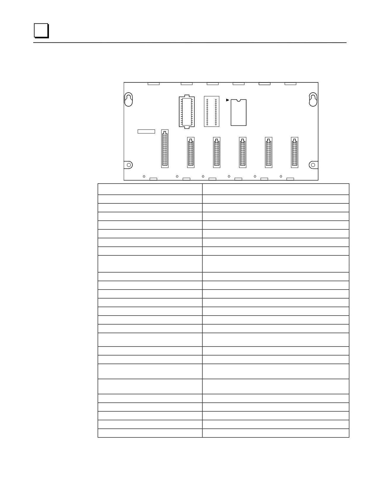
CPU311
Catalog Number IC693CPU311
PROGRAMMABLE
1
CONTROLLER
BASE 5-SLOT
WITH CPU
CAUTION
SYSTEM
PROGRAM
PROM
PROM
USER PROGRAM
AND REGISTER
VALUES MAY BE
LOST IF POWER
SUPPLY IS
REMOVED FOR
LONGER THAN
i HOUR
POWER
1
2
3
4
5
SUPPLY
CPU Type
5-slot baseplate with embedded CPU
Total Baseplates per System
1
Load Required from Power Supply
410 milliamps from +5 VDC supply
Processor Speed
10 MegaHertz
Processor Type
80188
Operating Temperature
0 to 60 degrees C (32 to 140 degrees F) ambient
Typical Scan Rate
18 milliseconds per 1K of logic (boolean contacts)
User Program Memory (maximum)
6K Bytes
Discrete Input Points - %I
160 (maximum - combined inputs + outputs)
Discrete Output Points - %Q
160 (maximum - combined outputs + inputs)
Discrete Global Memory - %G
1280 bits
Internal Coils - %M
1024 bits
Output (Temporary) Coils - %T
256 bits
System Status References - %S
128 bits (%S, %SA, %SB, %SC - 32 bits each)
Register Memory - %R
512 words
Analog Inputs - %AI
64 words
Analog Outputs - %AQ
32 words
System Registers (for reference table viewing
16 words (%SR)
only; cannot be referenced in user logic program)
Timers/Counters
170
Shift Registers
yes
Built-in Serial Ports
1 (uses connector on PLC power supply). Supports SNP slave
and SNP-X slave protocols.
Communications
LAN - Supports multidrop. Also supports Ethernet, FIP,
Profibus, GBC, GCM, GCM+ option modules.
Override
no
Battery Backed Clock
no
Interrupts
no
Type of Memory Storage
RAM and optional EPROM or EEPROM
PCM/CCM Compatibility
no
5-28
Series 90-30 PLC Installation and Hardware Manual - August 2002
GFK-0356Q
5
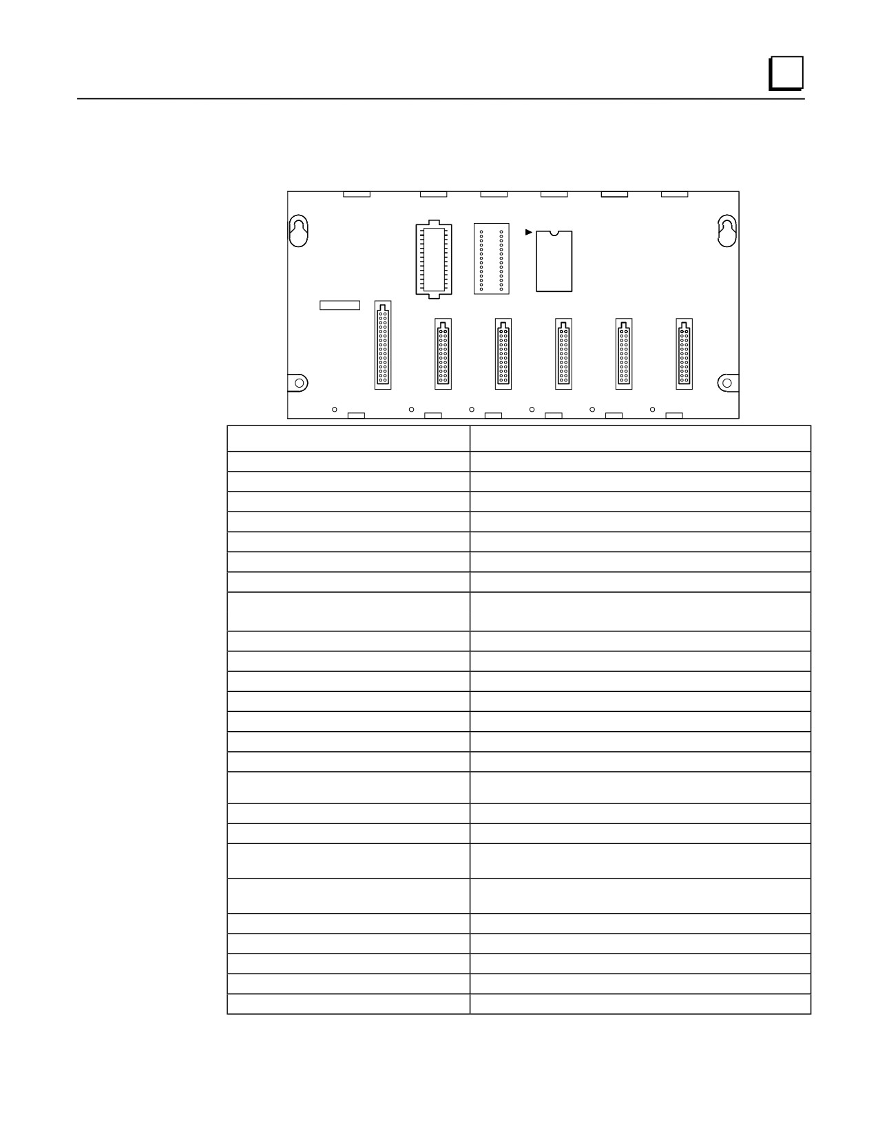
CPU313
Catalog Number IC693CPU313
PROGRAMMABLE
1
CONTROLLER
BASE 5-SLOT
WITH CPU
CAUTION
SYSTEM
PROGRAM
PROM
PROM
USER PROGRAM
AND REGISTER
VALUES MAY BE
LOST IF POWER
SUPPLY IS
REMOVED FOR
LONGER THAN
i HOUR
POWER
1
2
3
4
5
SUPPLY
CPU Type
5-slot baseplate with embedded CPU
Total Baseplates per System
1
Load Required from Power Supply
430 milliamps from +5 VDC supply
Processor Speed
10 MegaHertz
Processor Type
80188
Operating Temperature
0 to 60 degrees C (32 to 140 degrees F) ambient
Typical Scan Rate
0.6 milliseconds per 1K of logic (boolean contacts)
User Program Memory (maximum)
12K Bytes (6K bytes prior to release 7)
Discrete Input Points - %I
160 (maximum - combined inputs + outputs)
Discrete Output Points - %Q
160 (maximum - combined outputs + inputs)
Discrete Global Memory - %G
1280 bits
Internal Coils - %M
1024 bits
Output (Temporary) Coils - %T
256 bits
System Status References - %S
128 bits (%S, %SA, %SB, %SC - 32 bits each)
Register Memory - %R
1024 words
Analog Inputs - %AI
64 words
Analog Outputs - %AQ
32 words
System Registers (for reference table viewing
16 words (%SR)
only; cannot be referenced in user logic program)
Timers/Counters
170
Shift Registers
yes
Built-in Ports
1 (uses connector on PLC power supply). Supports SNP slave
and SNP-X slave protocols.
Communications
LAN - Supports multidrop. Also supports Ethernet, FIP,
Profibus, GBC, GCM, GCM+ option modules.
Override
no
Battery Backed Clock
no
Interrupts
no
Type of Memory Storage
RAM and optional EPROM or EEPROM
PCM/CCM Compatibility
no
GFK-0356Q
Chapter 5 CPUs
5-29
5
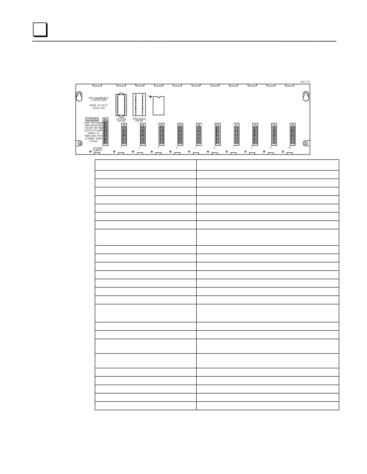
CPU323
Catalog Number IC693CPU323
CPU Type
10-slot baseplate with embedded CPU
Total Baseplates per System
1
Load Required from Power Supply
430 milliamps from +5 VDC supply
Processor Speed
10 MegaHertz
Processor Type
80188
Operating Temperature
0 to 60 degrees C (32 to 140 degrees F) ambient
Typical Scan Rate
0.6 milliseconds per 1K of logic (boolean contacts)
User Program Memory (maximum)
12K Bytes (6K bytes prior to release 7)
Discrete Input Points - %I
320 (maximum - combined inputs + outputs)
Discrete Output Points - %Q
320 (maximum - combined outputs + inputs)
Discrete Global Memory - %G
1280 bits
Internal Coils - %M
1024 bits
Output (Temporary) Coils - %T
256 bits
System Status References - %S
128 bits (%S, %SA, %SB, %SC - 32 bits each)
Register Memory - %R
1024 words
Analog Inputs - %AI
64 words
Analog Outputs - %AQ
32 words
System Registers (for reference table viewing
16 words (%SR)
only; cannot be referenced in user logic
program)
Timers/Counters
340
Shift Registers
yes
Built-in Ports
1 (uses connector on PLC power supply). Supports SNP slave
and SNP-X slave protocols.
Communications
LAN - Supports multidrop. Also supports Ethernet, FIP,
Profibus, GBC, GCM, GCM+ option modules.
Override
no
Battery Backed Clock
no
Interrupts
no
Type of Memory Storage
RAM and optional EPROM or EEPROM
PCM/CCM Compatibility
no
5-30
Series 90-30 PLC Installation and Hardware Manual - August 2002
GFK-0356Q
5
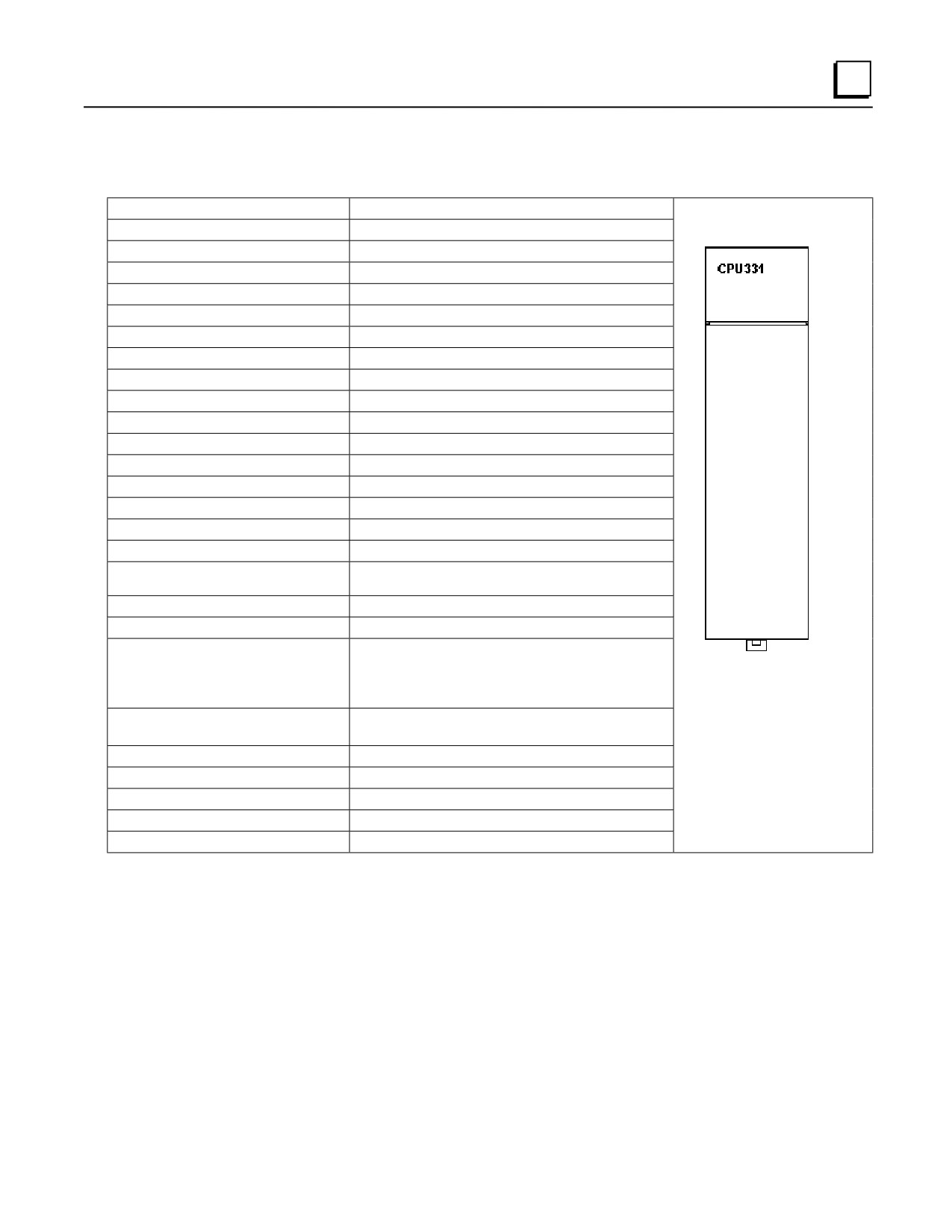
CPU331
Catalog Number IC693CPU331
CPU Type
Single slot CPU module
Total Baseplates per System
5 (1 CPU baseplate + 4 expansion and/or remote)
Load Required from Power Supply
350 milliamps from +5 VDC supply
Processor Speed
10 MegaHertz
Processor Type
80188
Operating Temperature
0 to 60 degrees C (32 to 140 degrees F) ambient
Typical Scan Rate
0.4 milliseconds per 1K of logic (boolean contacts)
User Program Memory (maximum)
16K Bytes
Discrete Input Points - %I
512
Discrete Output Points - %Q
512
Discrete Global Memory - %G
1280 bits
Internal Coils - %M
1024 bits
Output (Temporary) Coils - %T
256 bits
System Status References - %S
128 bits (%S, %SA, %SB, %SC - 32 bits each)
Register Memory - %R
2048 words
Analog Inputs - %AI
128 words
Analog Outputs - %AQ
64 words
System Registers (for reference table viewing
16 words (%SR)
only; cannot be referenced in user logic program)
Timers/Counters
680
Shift Registers
yes
Built-in Ports
1 (uses connector on PLC power supply). Supports
SNP/SNP-X slave protocols. Requires CMM module
for SNP/SNP-X master, CCM, or RTU slave support;
PCM module for RTU master support.
Communications
LAN - Supports multidrop. Also supports Ethernet,
FIP, Profibus, GBC, GCM, GCM+ option modules.
Override
yes
Battery Backed Clock
yes
Interrupts
no
Type of Memory Storage
RAM and optional EPROM or EEPROM
PCM/CCM Compatibility
Yes
GFK-0356Q
Chapter 5 CPUs
5-31
5
CPU340
Catalog Number IC693CPU340
CPU Type
Single slot CPU module
Total Baseplates per System
5 (1 CPU baseplate + 4 expansion and/or remote)
Load Required from Power Supply
490 milliamps from +5 VDC supply
CPU340
Processor Speed
20 MegaHertz
Processor Type
80C188XL
Operating Temperature
0 to 60 degrees C (32 to 140 degrees F) ambient
Typical Scan Rate
0.3 milliseconds per 1K of logic (boolean contacts)
User Program Memory (maximum)
32K Bytes
Discrete Input Points - %I
512
Discrete Output Points - %Q
512
Discrete Global Memory - %G
1280 bits
Internal Coils - %M
1024 bits
Output (Temporary) Coils - %T
256 bits
System Status References - %S
128 bits (%S, %SA, %SB, %SC - 32 bits each)
Register Memory - %R
9999 words
Analog Inputs - %AI
1024 words
Analog Outputs - %AQ
256 words
System Registers (for reference table viewing
16 words (%SR)
only; cannot be referenced in user logic program)
Timers/Counters
>2000
Shift Registers
yes
Built-in Ports
1 (uses connector on PLC power supply). Supports
SNP/SNP-X slave protocols. Requires CMM module for
SNP/SNP-X master, CCM, or RTU slave support; PCM
module for RTU master support.
Communications
LAN - Supports multidrop. Also supports Ethernet, FIP,
Profibus, GBC, GCM, GCM+ option modules.
Override
yes
Battery Backed Clock
yes
Interrupts
yes
Type of Memory Storage
RAM and optional Flash
PCM/CCM Compatibility
yes
5-32
Series 90-30 PLC Installation and Hardware Manual - August 2002
GFK-0356Q
5
CPU341
Catalog Number IC693CPU341
CPU Type
Single slot CPU module
Total Baseplates per System
5 (1 CPU baseplate + 4 expansion and/or remote)
Load Required from Power Supply
490 milliamps from +5 VDC supply
CPU341
Processor Speed
20 MegaHertz
Processor Type
80C188XL
Operating Temperature
0 to 60 degrees C (32 to 140 degrees F) ambient
Typical Scan Rate
0.3 milliseconds per 1K of logic (boolean contacts)
User Program Memory (maximum)
80K Bytes
Discrete Input Points - %I
512
Discrete Output Points - %Q
512
Discrete Global Memory - %G
1280 bits
Internal Coils - %M
1024 bits
Output (Temporary) Coils - %T
256 bits
System Status References - %S
128 bits (%S, %SA, %SB, %SC - 32 bits each)
Register Memory - %R
9999 words
Analog Inputs - %AI
1024 words
Analog Outputs - %AQ
256 words
System Registers (for reference table viewing
16 words (%SR)
only; cannot be referenced in user logic program)
Timers/Counters
>2000
Shift Registers
yes
Built-in Ports
1 (uses connector on PLC power supply). Supports
SNP/SNP-X slave protocols. Requires CMM module for
SNP/SNP-X master, CCM, or RTU slave support; PCM
module for RTU master support.
Communications
LAN - Supports multidrop. Also supports Ethernet, FIP,
Profibus, GBC, GCM, GCM+ option modules.
Override
yes
Battery Backed Clock
yes
Interrupts
yes
Type of Memory Storage
RAM and optional EPROM or EEPROM for early
versions. Starting with hardware version IC693CPU341-J
and firmware Release 4.61, only RAM and optional Flash
are supported.
PCM/CCM Compatibility
yes
GFK-0356Q
Chapter 5 CPUs
5-33
5
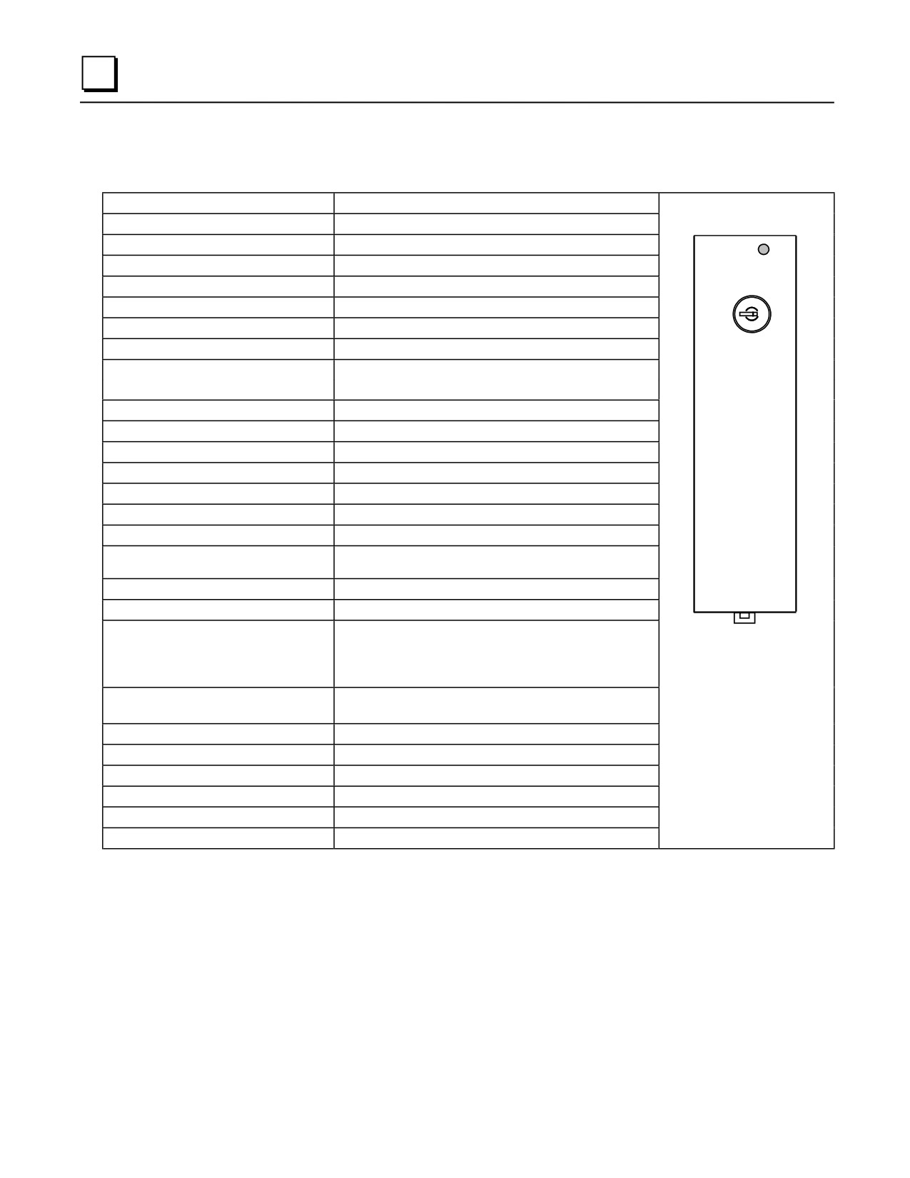
CPU350
Catalog Number IC693CPU350
CPU Type
Single slot CPU module
Total Baseplates per System
8 (CPU baseplate + 7 expansion and/or remote)
Load Required from Power Supply
670 milliamps from +5 VDC supply
PS
PORT
Processor Speed
25 MegaHertz
CPU 350
Processor Type
80386EX
ON
Operating Temperature
0 to 60 degrees C (32 to 140 degrees F) ambient
OFF
Typical Scan Rate
0.22 milliseconds per 1K of logic (boolean contacts)
User Program Memory (maximum)
32K Bytes (not configurable)
Discrete Input Points - %I
2,048
Discrete Output Points - %Q
2,048
Discrete Global Memory - %G
1,280 bits
Internal Coils - %M
4,096 bits
Output (Temporary) Coils - %T
256 bits
System Status References - %S
128 bits (%S, %SA, %SB, %SC - 32 bits each)
Register Memory - %R
9,999 words
Analog Inputs - %AI
2,048 words
Analog Outputs - %AQ
512 words
System Registers (for reference table viewing
28 words (%SR)
only; cannot be referenced in user logic program)
Timers/Counters
>2,000
Shift Registers
Yes
Built-in Serial Port
1 (uses connector on PLC power supply). Supports
SNP/SNP-X slave protocols. Requires CMM module for
SNP/SNP-X master, CCM, or RTU slave protocol
support; PCM module for RTU master support.
Communications
LAN - Supports multidrop. Also supports Ethernet, FIP,
Profibus, GBC, GCM, GCM+ option modules.
Override
Yes
Battery Backed Clock
Yes
Interrupts
Supports the periodic subroutine feature
Type of Memory Storage
RAM and Flash
PCM/CCM Compatibility
Yes
Floating Point Math Support
Yes. Firmware-based in firmware releases 9.0 and later.
5-34
Series 90-30 PLC Installation and Hardware Manual - August 2002
GFK-0356Q
5
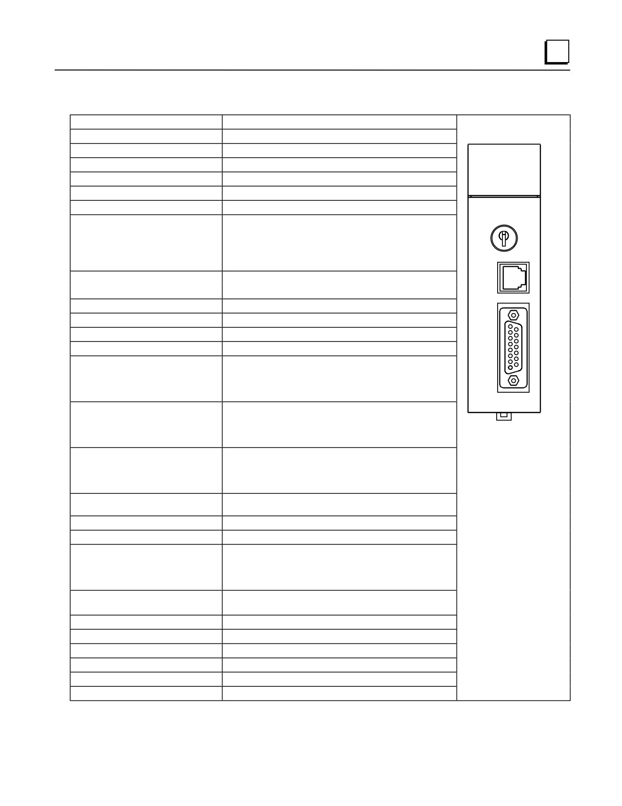
CPU351
Catalog Number IC693CPU351
CPU Type
Single slot CPU module
Total Baseplates per System
8 (CPU baseplate + 7 expansion and/or remote)
Load Required from Power Supply
890 milliamps from +5 VDC supply
CPU 351
SNP
Processor Speed
25 MegaHertz
P1
Processor Type
80386EX
P2
Operating Temperature
0 to 60 degrees C (32 to 140 degrees F) ambient
Typical Scan Rate
0.22 milliseconds per 1K of logic (boolean contacts)
User Program Memory (maximum)
Starting with firmware Release 9.0, 240K Bytes. Note:
ON/RUN
Actual size of available user program memory depends on the
OFF/
amounts configured for the %R, %AI, and %AQ configurable
STOP
word memory types (see below).
For firmware prior to Release 9.0, fixed size is 80K bytes.
PORT 1
Discrete Input Points - %I
2,048
RS-232
Discrete Output Points - %Q
2,048
Discrete Global Memory - %G
1,280 bits
Internal Coils - %M
4,096 bits
Output (Temporary) Coils - %T
256 bits
PORT 2
System Status References - %S
128 bits (%S, %SA, %SB, %SC - 32 bits each)
RS-485
Register Memory - %R
Starting with firmware Release 9.0, configurable in 128 word
increments from 128 to 16,384 word with Logicmaster and
from 128 to 32,640 words with Control version 2.2. For
firmware prior to Release 9.0, fixed size is 9,999 words.
Analog Inputs - %AI
Starting with firmware Release 9.0, configurable in 128 word
increments from 128 to 16,384 word with Logicmaster and
from 128 to 32,640 words with Control version 2.2. For
firmware prior to Release 9.0, fixed size is 9,999 words.
Model 351 CPU
Analog Outputs - %AQ
Starting with firmware Release 9.0, configurable in 128 word
increments from 128 to 16,384 word with Logicmaster and
from 128 to 32,640 words with Control version 2.2. For
firmware prior to Release 9.0, fixed size is 9,999 words.
System Registers (for reference table viewing
28 words (%SR)
only; cannot be referenced in logic program)
Timers/Counters
>2,000
Shift Registers
Yes
Built-in Serial Ports
Three ports. Supports SNP/SNPX slave (on power supply
connector) and RTU slave, SNP/SNPX master/slave , Serial
I/O (on Ports 1 and 2). Requires CMM module for CCM;
PCM module for RTU master support.
Communications
LAN - Supports multidrop. Also supports Ethernet, FIP,
Profibus, GBC, GCM, GCM+ option modules.
Override
Yes
Battery Backed Clock
Yes
Interrupt Support
Supports the Periodic Subroutine feature.
Type of Memory Storage
RAM and Flash
PCM/CCM Compatibility
Yes
Floating Point Math Support
Yes, firmware-based in firmware Release 9.0 and later.
The CPU351 is supported by Logicmaster 90-30/20/Micro programming and configuration software Release 6.00 and
later releases, and Control programming and configuration software Release 2.0 and later releases.
GFK-0356Q
Chapter 5 CPUs
5-35
5
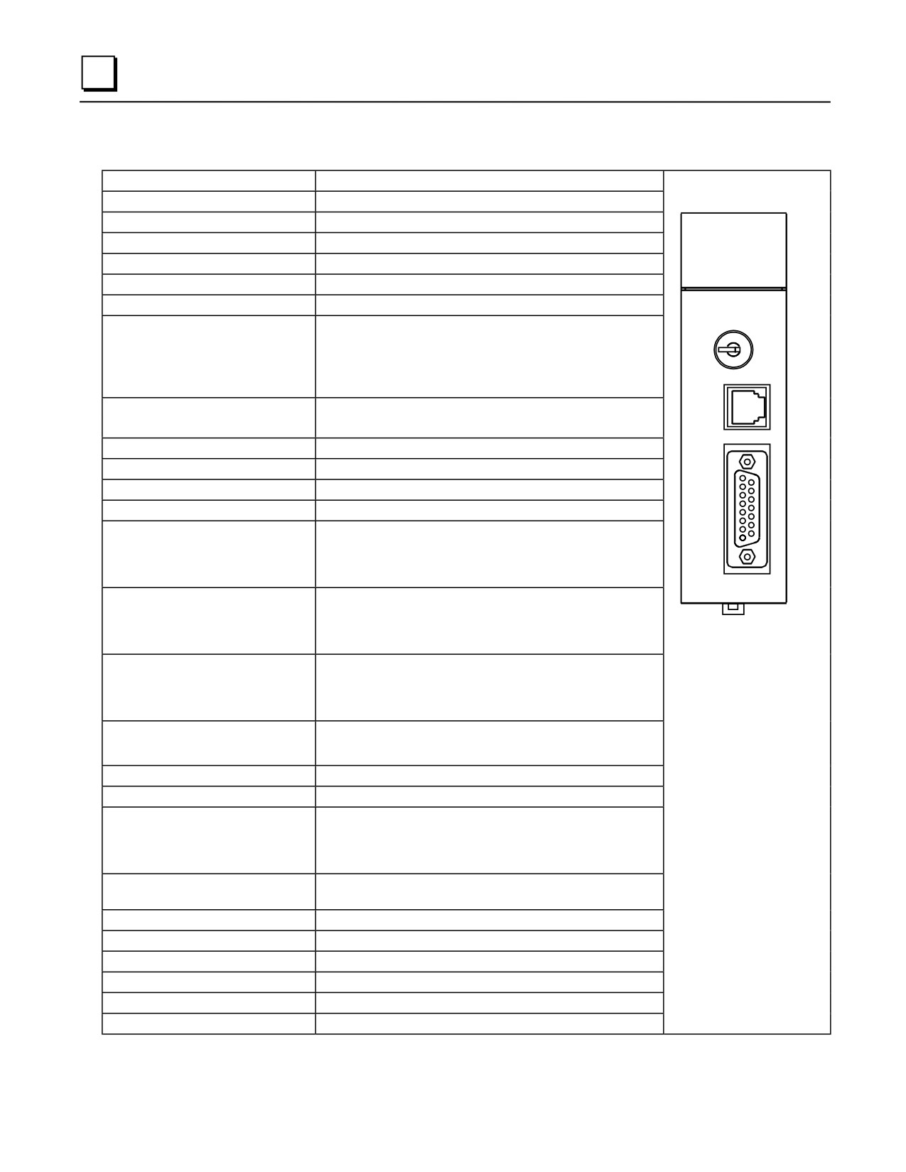
CPU352
Catalog Number IC693CPU352
CPU Type
Single slot CPU module
Total Baseplates per System
8 (CPU baseplate + 7 expansion and/or remote)
Load Required from Power Supply
890 milliamps from +5 VDC supply
CPU 352
SNP
Processor Speed
25 MegaHertz
P1
Processor Type
80386EX
P2
Operating Temperature
0 to 60 degrees C (32 to 140 degrees F) ambient
Typical Scan Rate
0.22 milliseconds per 1K of logic (boolean contacts)
User Program Memory (maximum)
Starting with firmware Release 9.0, 240K Bytes. Note: Actual
ON/RUN
size of available user program memory depends on the
OFF/
amounts configured for the %R, %AI, and %AQ configurable
STOP
word memory types (see below).
For firmware prior to Release 9.0, fixed size is 80K bytes.
PORT 1
Discrete Input Points - %I
2,048
RS-232
Discrete Output Points - %Q
2,048
Discrete Global Memory - %G
1,280 bits
Internal Coils - %M
4,096 bits
Output (Temporary) Coils - %T
256 bits
PORT 2
System Status References - %S
128 bits (%S, %SA, %SB, %SC - 32 bits each)
RS-485
Register Memory - %R
Starting with firmware Release 9.0, configurable in 128 word
increments from 128 to 16,384 word with Logicmaster and
from 128 to 32,640 words with Control version 2.2. For
firmware prior to Release 9.0, fixed size is 9,999 words.
Analog Inputs - %AI
Starting with firmware Release 9.0, configurable in 128 word
increments from 128 to 16,384 word with Logicmaster and
from 128 to 32,640 words with Control version 2.2. For
firmware prior to Release 9.0, fixed size is 9,999 words.
Model 352 CPU
Analog Outputs - %AQ
Starting with firmware Release 9.0, configurable in 128 word
increments from 128 to 16,384 word with Logicmaster and
from 128 to 32,640 words with Control version 2.2. For
firmware prior to Release 9.0, fixed size is 9,999 words.
System Registers (for reference table
28 words (%SR)
viewing only; cannot be referenced in logic
program)
Timers/Counters
>2,000
Shift Registers
Yes
Built-in Serial Ports
Three ports. Supports SNP/SNPX slave (on power supply
connector) and RTU slave, SNP/SNPX master/slave , Serial
I/O (on Ports 1 and 2). Requires CMM module for CCM;
PCM module for RTU master support.
Communications
LAN - Supports multidrop. Also supports Ethernet, FIP,
Profibus, GBC, GCM, GCM+ option modules.
Override
Yes
Battery Backed Clock
Yes
Interrupt Support
Supports the Periodic Subroutine feature.
Type of Memory Storage
RAM and Flash
PCM/CCM Compatibility
Yes
Floating Point Math Support
Yes, hardware-based (built-in math co-processor)
The CPU352 is supported by Logicmaster 90-30/20/Micro programming and configuration software Release 7.00 and
later releases, and Control programming and configuration software Release 2.0 and later releases.
5-36
Series 90-30 PLC Installation and Hardware Manual - August 2002
GFK-0356Q
5
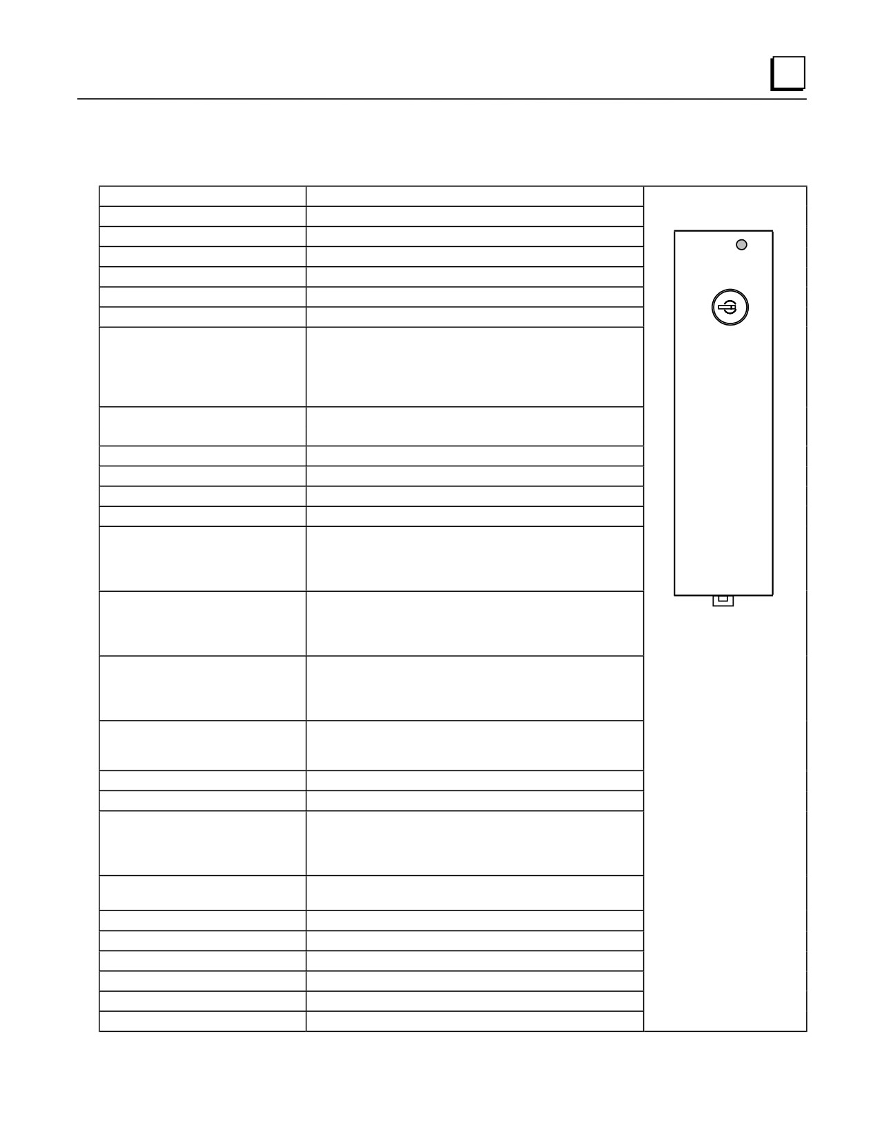
CPU360
Catalog Number IC693CPU360
CPU Type
Single slot CPU module
Total Baseplates per System
8 (CPU baseplate + 7 expansion and/or remote)
Load Required from Power Supply
670 milliamps from +5 VDC supply
PS
PORT
Processor Speed
25 MegaHertz
CPU 360
Processor Type
80386EX
ON
Operating Temperature
0 to 60 degrees C (32 to 140 degrees F) ambient
OFF
Typical Scan Rate
0.22 milliseconds per 1K of logic (boolean contacts)
User Program Memory (maximum)
Starting with firmware Release 9.0, 240K Bytes. Note: Actual
size of available user program memory depends on the
amounts configured for the %R, %AI, and %AQ configurable
word memory types (see below). For firmware prior to
Release 9.0, fixed size is 80K bytes.
Discrete Input Points - %I
2,048
Discrete Output Points - %Q
2,048
Discrete Global Memory - %G
1,280 bits
Internal Coils - %M
4,096 bits
Output (Temporary) Coils - %T
256 bits
System Status References - %S
128 bits (%S, %SA, %SB, %SC - 32 bits each)
Register Memory - %R
Starting with firmware Release 9.0, configurable in 128 word
increments from 128 to 16,384 words with Logicmaster and
from 128 to 32,640 words with Control version 2.2. For
firmware prior to Release 9.0, fixed size is 9,999 words.
Analog Inputs - %AI
Starting with firmware Release 9.0, configurable in 128 word
increments from 128 to 16,384 words with Logicmaster and
from 128 to 32,640 words with Control version 2.2. For
firmware prior to Release 9.0, fixed size is 9,999 words.
Analog Outputs - %AQ
Starting with firmware Release 9.0, configurable in 128 word
increments from 128 to 16,384 words with Logicmaster and
from 128 to 32,640 words with Control version 2.2. For
firmware prior to Release 9.0, fixed size is 9,999 words.
System Registers (for reference table
28 words (%SR)
viewing only; cannot be referenced in
logic program)
Timers/Counters
>2,000
Shift Registers
Yes
Built-in Serial Ports
1 (uses connector on PLC power supply). Supports SNP slave
and SNP-X slave protocols. Requires CMM module for
SNP/SNP-X master, CCM, or RTU slave protocol support;
PCM module for RTU master support.
Communications
LAN - Supports multidrop. Also supports Ethernet, FIP,
Profibus, GBC, GCM, and GCM+ option modules.
Override
Yes
Battery Backed Clock
Yes
Interrupts
Yes
Type of Memory Storage
RAM and Flash
PCM/CCM Compatibility
Yes
Floating Point Math Support
Yes, firmware-based in firmware Release 9.0 and later.
GFK-0356Q
Chapter 5 CPUs
5-37
5
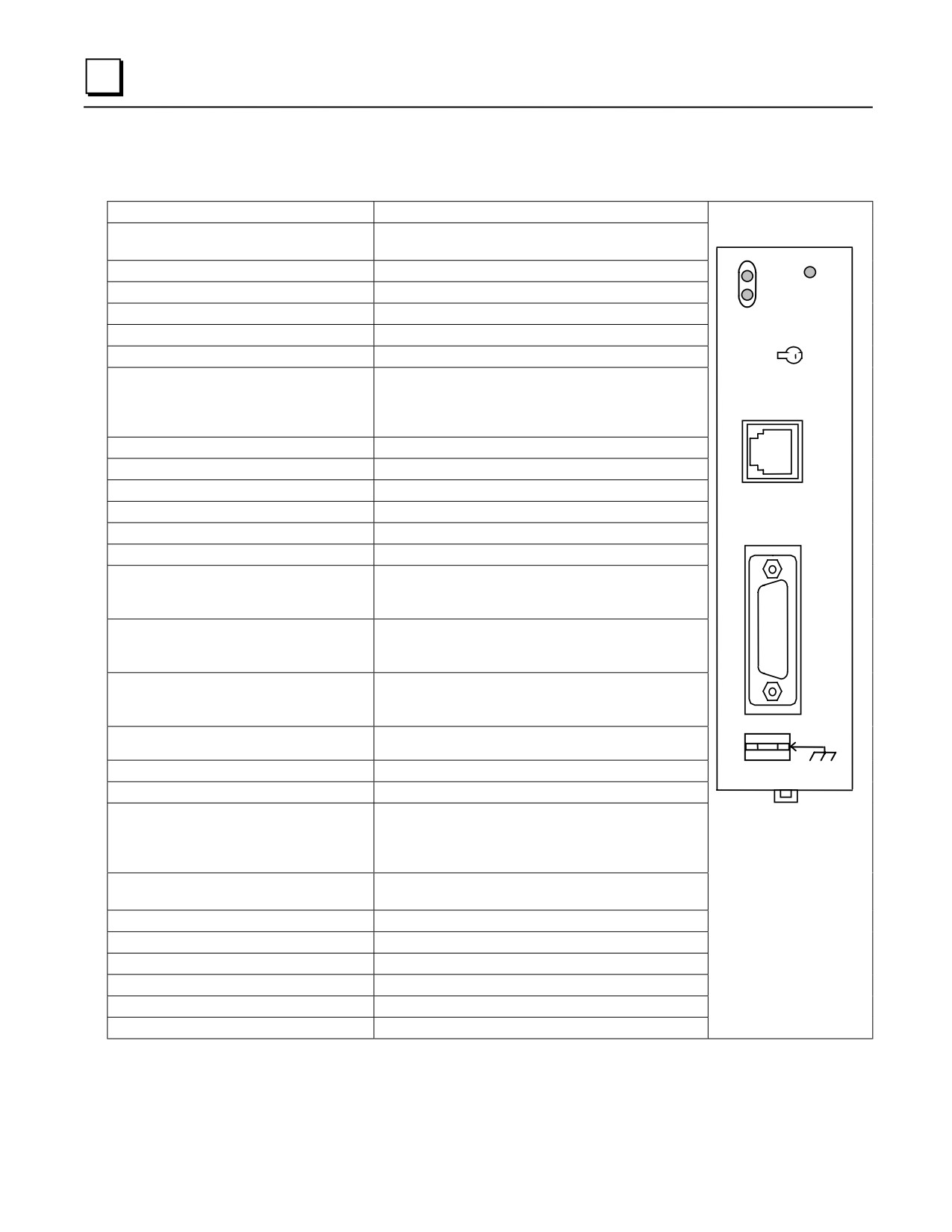
CPU363
Catalog Number IC693CPU363
CPU Type
Single slot CPU module
Total Baseplates per System
8
(CPU baseplate + 7 expansion and/or remote)
Load Required from Power Supply
890 milliamps from +5 VDC supply
PS
P1
PORT
Processor Speed
25 MegaHertz
P2
CPU 363
Processor Type
80386EX
ON
Operating Temperature
0 to 60 degrees C (32 to 140 degrees F) ambient
Typical Scan Rate
0.22 milliseconds per 1K of logic (boolean contacts)
OFF
User Memory (total)
240K (245,760) Bytes. Actual size of available user
program memory depends on the amounts configured for
%R, %AI, and %AQ configurable word memory types
(see below).
Discrete Input Points - %I
2,048
PORT 1
RS-232
Discrete Output Points - %Q
2,048
Discrete Global Memory - %G
1,280 bits
Internal Coils - %M
4,096 bits
Output (Temporary) Coils - %T
256 bits
System Status References - %S
128 bits (%S, %SA, %SB, %SC - 32 bits each)
Register Memory - %R
Configurable in 128 word increments from 128 to 16,384
words with Logicmaster and from 128 to 32,640 words
with Control version 2.2.
PORT 2
Analog Inputs - %AI
Configurable in 128 word increments from 128 to 16,384
RS-485
words with Logicmaster and from 128 to 32,640 words
with Control version 2.2.
Analog Outputs - %AQ
Configurable in 128 word increments from 128 to 16,384
words with Logicmaster and from 128 to 32,640 words
with Control version 2.2.
System Registers (for reference table viewing only;
28 words (%SR)
FRAME
cannot be referenced in user logic program)
Timers/Counters
>2,000
Shift Registers
Yes
Built-in Ports
Three ports. Supports SNP/SNPX slave (on power
supply connector). On Ports 1 and 2, supports
SNP/SNPX master/slave and RTU slave. Requires CMM
module for CCM; PCM module for RTU master support.
Communications
LAN - Supports multidrop. Also supports Ethernet, FIP,
Profibus, GBC, GCM, GCM+ option modules.
Override
Yes
Battery Backed Clock
Yes
Interrupt Support
Supports the periodic subroutine feature.
Type of Memory Storage
RAM and Flash
PCM/CCM Compatibility
Yes
Floating Point Mat h Support
Yes, firmware-based in firmware Release 9.0 and later.
5-38
Series 90-30 PLC Installation and Hardware Manual - August 2002
GFK-0356Q
5
CPU364
Catalog Number IC693CPU364
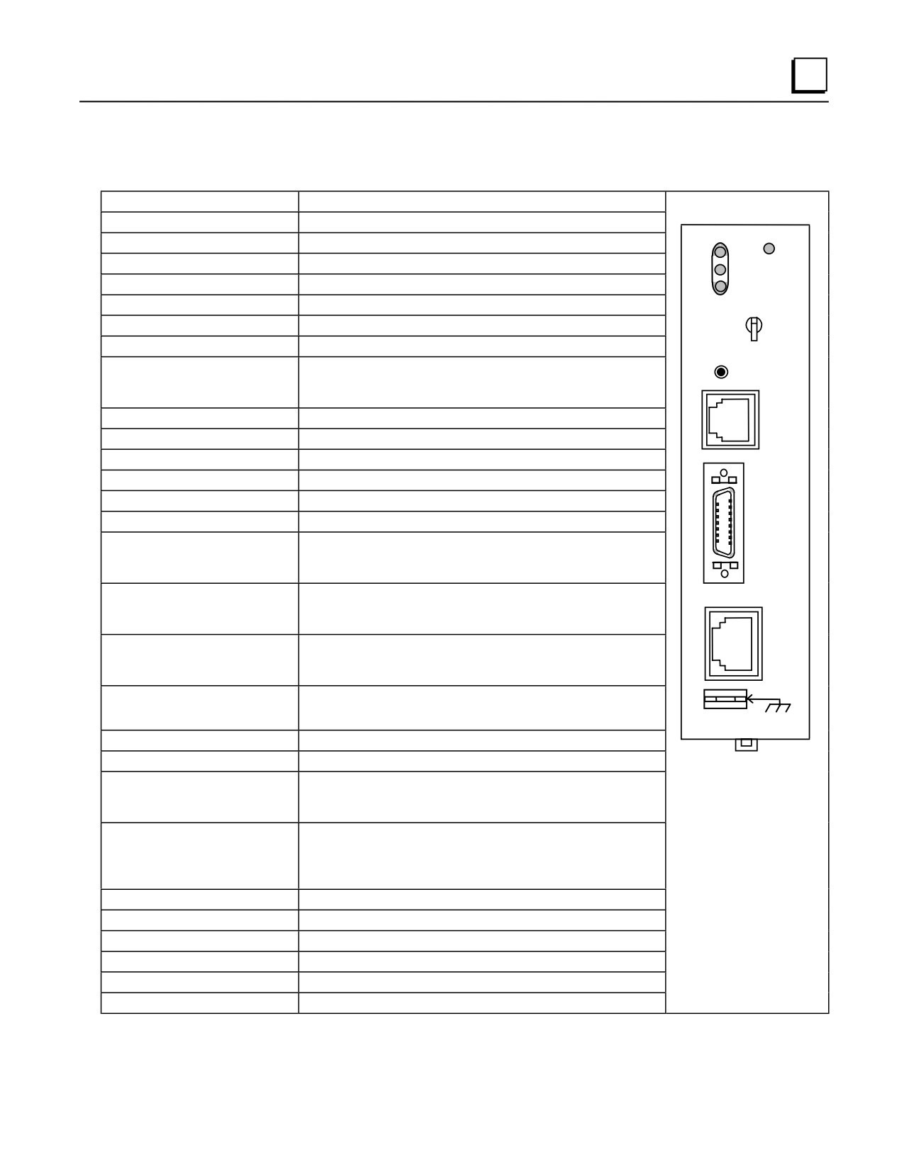
CPU Type
Single slot CPU module with embedded Ethernet Interface
Total Baseplates per System
8 (CPU baseplate + 7 expansion and/or remote)
Load Required from Power Supply
1.51 Amps from +5 VDC supply
EOK
SNP
Processor Speed
25 MegaHertz
LAN
CPU 364
Processor Type
80386EX
STAT
ON
Ethernet fuse, replaceable
2.69x2.69x6.1 mm, 125V, 1A, slow acting
Operating temperature
0 to 60 degrees C (32 to 140 degrees F) ambient
OFF
Typical Scan Rate
0.22 milliseconds per 1K of logic (boolean contacts)
User Memory (total)
240K Bytes. Note: Actual size of available user program memory
ETHERNET
depends on the amounts configured for %R, %AI, and %AQ
RESTART
configurable word memory types (see below).
Discrete Input Points - %I
2,048
PORT 1
RS_232
Discrete Output Points - %Q
2,048
Discrete Global Memory - %G
1,280 bits
Internal Coils - %M
4,096 bits
Output (Temporary) Coils - %T
256 bits
System Status References - %S
128 bits (%S, %SA, %SB, %SC - 32 bits each)
AAUI
Register Memory - %R
Configurable in 128 word increments from 128 to 16,384 words
with Logicmaster and from 128 to 32,640 words with Control
version 2.2.
Analog Inputs - %AI
Configurable in 128 word increments from 128 to 16,384 words
with Logicmaster and from 128 to 32,640 words with Control
version 2.2.
Analog Outputs - %AQ
Configurable in 128 word increments from 128 to 16,384 words
10BASE T
with Logicmaster and from 128 to 32,640 words with Control
version 2.2.
FRAME
System Registers (for reference table
28 words (%SR)
viewing only; cannot be referenced in logic
program)
Timers/Counters
>2,000
Shift Registers
Yes
Built-in Serial Ports
1 (uses connector on PLC Power Supply). Supports SNP/SNPX
slave. Requires CMM module for SNP/SNP-X master, RTU slave,
or CCM; PCM module for RTU master support.
Communications
Ethernet (internal) - AAUI or 10BASE-T. AAUI requires
external transceiver.
10BASE-T is direct.
Ethernet (additional) - Supports Ethernet option modules.
LAN-Requires option modules for Genius, Profibus, FIP.
Override
Yes
Battery Backed Clock
Yes
Interrupt Support
Supports the periodic subroutine feature.
Type of Memory Storage
RAM and Flash
PCM/CCM Compatibility
Yes
Floating Point Math Support
Yes, firmware-based.
Note: On some early modules, the LED labeled “PS PORT” may say “SNP” instead; otherwise,
the modules are identical.
GFK-0356Q
Chapter 5 CPUs
5-39
5
CPU374
Catalog Number IC693CPU374
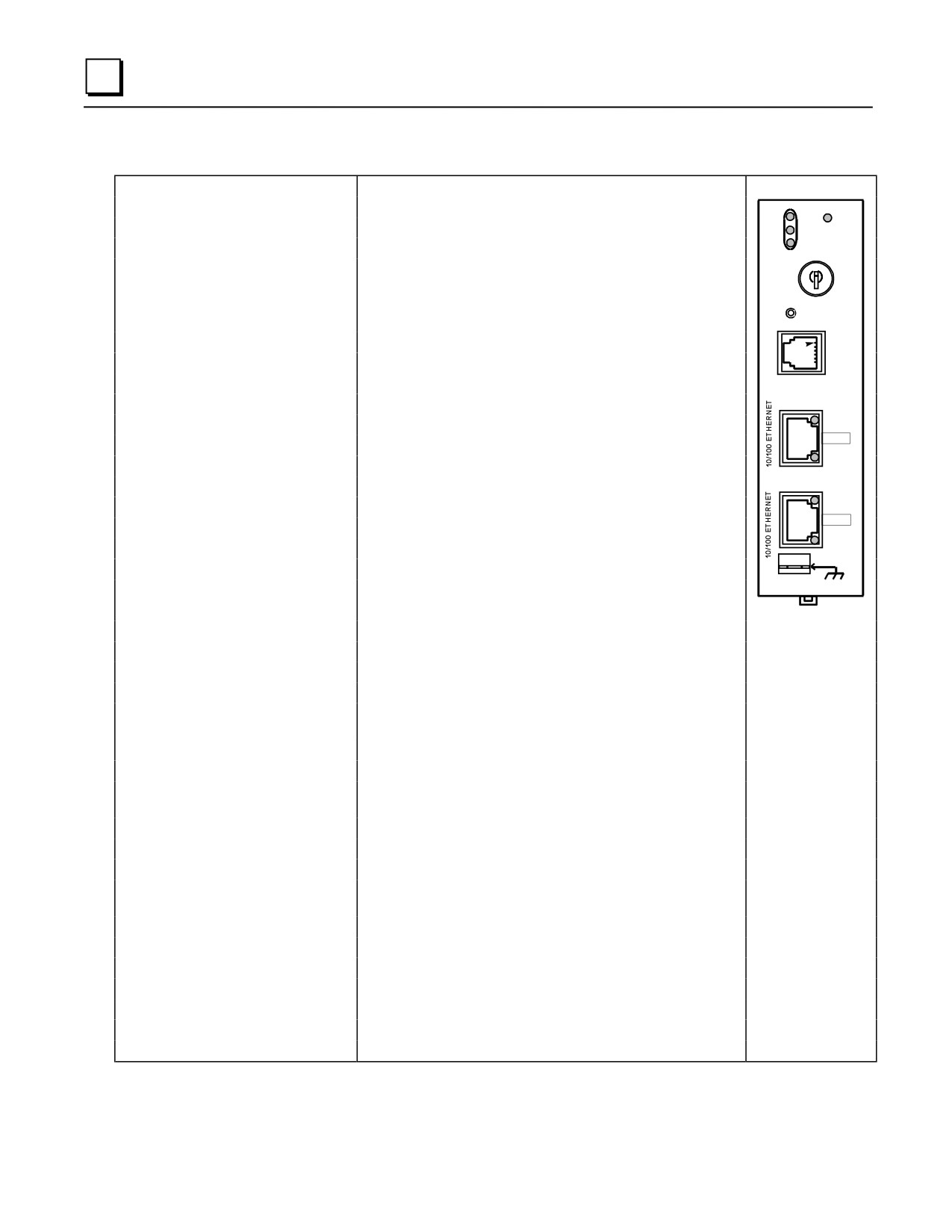
CPU type
Single slot CPU module with embedded Ethernet Interface
Processor speed
133 MHz
PS
EOK
PORT
Processor Type
Embedded 586
LAN
Typical Scan Rate
0.15 milliseconds per 1K of logic (boolean contacts)
STAT
CPU 374
ON
Type of Memory Storage
RAM and Flash
OFF
User Memory (total)
240KB (245,760) Bytes. Note: Actual size of available user
program memory depends on the amounts configured for %R,
ETHERNET
%AI, and %AQ configurable word memory types.
RESTART
Discrete Input Points - %I
2,048 (fixed)
STATION
MGR
Discrete Output Points - %Q
2,048 (fixed)
Discrete Global Memory - %G
1,280 bits (fixed)
Internal Coils - %M
4,096 bits (fixed)
LINK/ACT
Output (Temporary) Coils - %T
256 bits (fixed)
PORT 1
System Status References - %S
128 bits (%S, %SA, %SB, %SC - 32 bits each) (fixed)
100Mbps
Register Memory - %R
Configurable 128 to 32,640 words
Analog Inputs - %AI
Configurable 128 to 32,640 words
LINK/ACT
Analog Outputs - %AQ
Configurable 128 to 32,640 words
PORT 2
System Registers - %SR
28 words (fixed)
100Mbps
Timers/Counters
>2,000 (depends on available user memory)
FRAME
Battery Backed Clock
Yes
Battery Back Up (Number of months
1.2 months for internal battery (installed in the power supply)
with no power)
15 months with external battery (IC693ACC302)
Load Required from Power Supply
7.4 watts of 5VDC. High Capacity power supplies recommended.
EZ Program Store Device
Yes
Total Baseplates per System
8 (CPU baseplate + 7 expansion and/or remote)
Interrupt Support
Supports the periodic subroutine feature.
Communications and Programmable
Yes
Coprocessor Compatibility
Override
Yes
Floating Point Math
Yes, Hardware Floating Point Math
Programming Support
VersaPro 2.03 or later. CIMPLICITY Machine Edition Logic
Developer 2.60 or later. Control software version 2.50 or later.
Built-in Serial Ports
None. Supports RS-485 port on power supply.
Protocol Support
SNP and SNPX on power supply RS-485 port
Built-in Ethernet Communications
Ethernet (built-in) - 10/100 base-T/TX Ethernet Switch
Number of Ethernet Ports
Two, both are 10/100baseT/TX ports with auto sensing. RJ-45
connection.
Number of IP Addresses
One
Protocols
SRTP and Ethernet Global Data (EGD). No channel support.
Web Server Support
None
Operating Temperature
0 to 60°C (32 to 140°F) ambient
Storage Temperature
-40°C to +85°C
Agency Approvals
UL508, C-UL (Class I, DIV II, A, B, C, D), CE Mark
Low Temperature (LT) Testing
Yes. The CPU374 is available for -40° to 60°C operation.
5-40
Series 90-30 PLC Installation and Hardware Manual - August 2002
GFK-0356Q
Chapter
Memory Backup/Battery Backup
6
Backup Battery for RAM Memory (All Supplies)
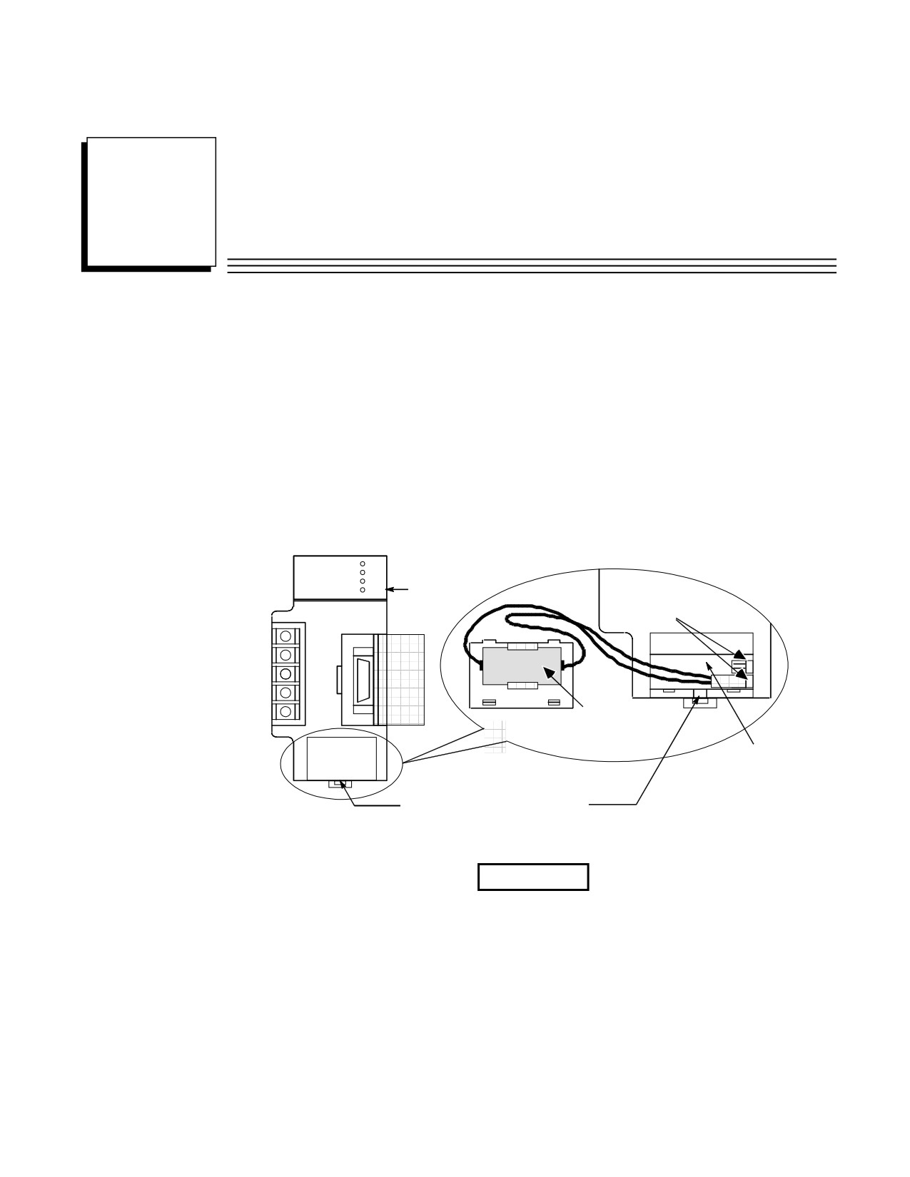
The long-life Lithium battery (IC693ACC301) used to maintain the contents of the CMOS RAM
memory in the CPU is accessed by removing the cover plate located at the bottom of the power
supply faceplate. This battery is mounted on a plastic clip attached to the inside of this cover.
The battery is wired to a small Berg female connector that connects to either of the two Berg male
connectors mounted on the Power Supply printed circuit board. This battery can be replaced with
power applied to the PLC.
PWR
OK
RUN
Low Battery
BATT
Warning LED
BATTERY
CONNECTORS
B
A
T
T
E
R
Y
LITHIUM
BACK-UP
BATTERY
Battery
Cavity
Battery Cover Removal Notch
Figure 6-1. Backup Battery for RAM Memory
Caution
If a Low Battery Warning (BATT LED turns ON) occurs, replace the
battery located in the power supply before removing power from the rack.
Otherwise, there is a possibility that data will be corrupted or the
application program will be cleared from memory.
GFK-0356Q
6-1
6
Battery Replacement Instructions
Warning
To avoid the chance of losing the contents of RAM memory, you can
carefully perform the following steps with PLC power ON. This procedure
should only be performed by qualified electrical personnel who are trained
in applicable electrical safety rules and procedures. Failure to follow
standard electrical safety practice can result in injury or death to personnel,
damage to equipment, or both.
■
Carefully insert the tip a small pocket-size screwdriver approximately 1/4 inch (6 mm) into the
battery cover removal slot, located beneath the battery cover (see previous figure).
■
Gently rotate the screwdriver about 45 degrees to loosen the cover.
■
Remove cover with fingers. The battery is mounted in a clip on the back of the cover. It has a
pair of leads with a connector that is plugged-in to a connector on a circuit board inside the
power supply.
■
Carefully reach into battery cavity with your fingers (do not use a metal object to do this) and
unplug the battery connector.
■
Remove the old battery from the clip on the battery cover and set it aside. Be careful not to
mix it up with the new battery.
■
Carefully reach into battery cavity with your fingers (do not use a metal object to do this) and
plug in new battery connector.
■
Clip new battery into clip on battery cover.
■
Snap battery cover back onto power supply.
6-2
Series 90-30 PLC Installation and Hardware Manual - August 2002
GFK-0356Q
6
Battery Replacement/Memory Protection Factors
Since there are differences in each PLC application, each user will have to determine on an
individual basis what strategy to use. There are several factors to consider when planning a battery
replacement/memory protection strategy:
■ How critical is the application? Will considerable loss be sustained if the PLC goes down? If
so, frequent replacement of the battery would be a wise choice. For critical applications, the
cost of a battery would be quite low in comparison to the cost of a PLC shut-down.
■ How readily can a backup program be loaded? Are there technicians on-site who know how to
load a backup program? Is the backup program accessible at all times to those responsible for
maintaining the equipment? Is a personal computer or equivalent equipped with GE Fanuc
programming software available at all times for use in loading the backup program?
■ Do you have a preventive maintenance program? A formal program would help ensure that
the battery is replaced on time. Some users replace the backup battery each year during their
annual shut-down period.
■ How accessible is the PLC? In some applications, the PLC may be mounted in a remote
location that is not easily accessed.
■ Safety codes. Some users may have safety rules that would not allow replacing the battery
with power applied.
■ How is the PLC used? Is power left on all the time, or is it shut down every day? See the
heading “Factors Affecting Battery Life.”
■ Some users run without a backup battery by using one of the PROM options. See the section
below called “Operating Without a Memory Backup Battery” to determine if this strategy is
suitable for your application.
The Importance of Backing up Your Program
Regardless of what strategy you use to maintain PLC memory, you should always keep an up-to-
date backup copy of your application program. Other suggestions to help minimize down time:
■ Make sure the backup copy is readily accessible to those who may need to use it.
■ Train more than one person to load the backup program in case that one person is not available
when needed. Information on creating a backup can be found in GE Fanuc ’s software user’s
manuals. This procedure is also covered in applicable GE Fanuc programming software
training courses.
■ Ensure that a suitable computer is equipped with GE Fanuc PLC programming software and
will be readily available to load the backup program to the PLC.
■ Create a written backup procedure. Fortunately, restoring your program from the backup copy
is probably not something you will do very often. As a result, however, some of the steps
could easily be forgotten.
GFK-0356Q
Chapter 6 Memory Backup/Battery Backup
6-3
6
Factors Affecting Battery Life
Replacing your battery once per year is a good rule of thumb. However, no one can predict
precisely how long a backup battery will last because this depends upon what CPU is used, what
temperature it is subjected to, and how it used. Considering the following list of factors that affect
battery life will help you decide how frequently to replace the battery in your application:
■ A battery that is not in use has an estimated life (called its ”shelf life”) of 5 years at ”room
temperature” (25 degrees C, or 77 degrees F).
■ A battery that is used continuously (supplying current to memory circuits with PLC power off)
if used at room temperature has an estimated average life as follows:
Model
Estimated Average Life
at Room Temperature
CPU models 311, 313 and 323
2 years
CPU models 331—364
1 year
CPU374
1.2 months
■ As long as a PLC is powered up, its battery is not being used; so how often you power down
your PLC has a direct affect on battery life. Some users keep their PLC powered up all of the
time while others turn theirs off every night.
■ Temperature has a relatively large affect on battery life. Temperatures considerably above
room temperature (25 degrees C, or 77 degrees F), or below freezing (0 degrees C, or 32
degrees F) will appreciably shorten battery life.
■ The type of CPU has a small affect on battery life. Some CPUs have more memory than
others. Some memory types require more power. Also, some CPUs have a clock and some do
not. More memory requires more battery current to maintain its contents; and a clock requires
battery current to maintain its operation.
Low Battery Warning Methods
There are three basic ways that the PLC warns of a low battery:
■ The red ”BATT” LED on the Power Supply module lights when the battery is low. The
disadvantage of this method is that the PLC is often mounted in an enclosure, so this LED
might not be easily seen.
■ The PLC Fault Table is updated with a battery low message. Viewing the PLC Fault Table
requires that a programmer be connected to the PLC.
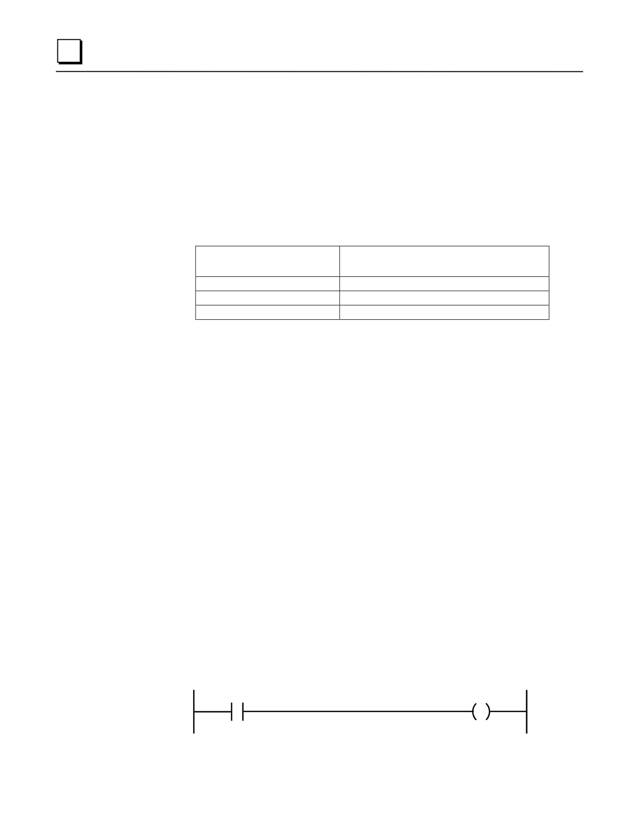
■ Certain System Reference bits are set to logic 1 when the battery is low. These are %SA011
(LOW_BAT), %SC009 (ANY_FLT), %S010 (SY_FLT), and %SC012 (SY_PRES). The most
specific is %SA011 (LOW_BAT). This bit could be used as a contact in your ladder logic
program to turn on an output that controls a warning light on an operator panel (as in the
example rung below), or to send a warning to an operator interface terminal.
%SA011
%Qxxx
6-4
Series 90-30 PLC Installation and Hardware Manual - August 2002
GFK-0356Q