FANUC Series 90-30 PLC. Installation and Hardware Manual (GFK-0356Q) - page 4

4
Table 4-5. Specifications for IC693PWR330 High Capacity AC/DC Input Power Supply
Nominal Rated Voltage
120/240 VAC or 125 VDC
Input Voltage Range
AC
85 to 264 VAC
DC
100 to 300 VDC
Input Power
100 VA with VAC Input
(Maximum with Full Load)
50 W with VDC Input
Inrush Current
4A peak, 250 ms maximum
Output Power
5 VDC:
30 watts maximum
24 VDC Relay:
15 watts maximum
24 VDC Isolated: 20 watts maximum
NOTE: 30 watts maximum total (all three outputs)
Output Voltage
5 VDC: 5.0 VDC to 5.2 VDC (5.1 VDC nominal)
24 VDC Relay:
24 to 28 VDC
24 VDC Isolated:
21.5 VDC to 28 VDC
Protective Limits
Overvoltage:
5 VDC output: 6.4 to 7 V
Overcurrent:
5 VDC output: 7 A maximum
Holdup Time:
20 ms minimum
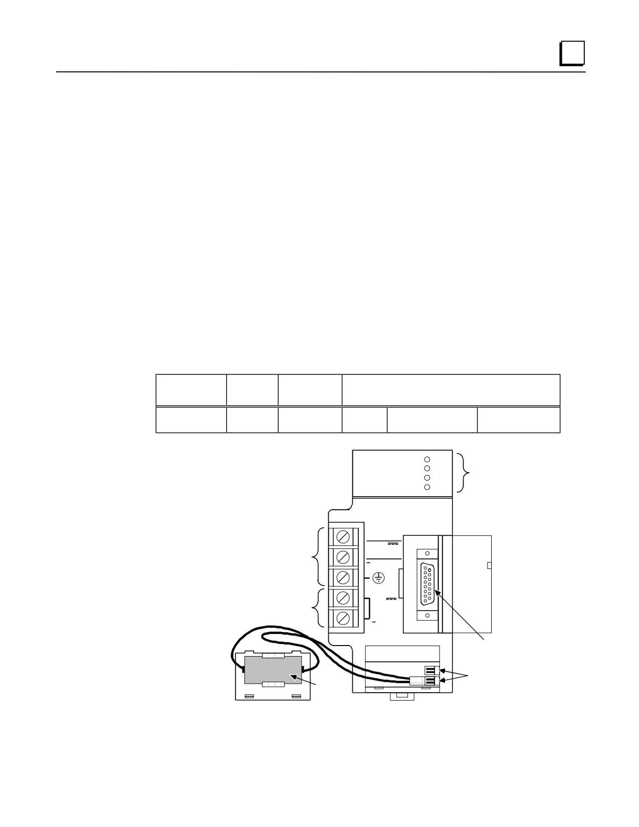
Field Wiring Connections for the AC/DC Input Power Supplies
The two AC/DC input power supplies have six terminals for user connections. These connections
are described below.
AC Power Source Connections
The Hot, Neutral, and Ground wires from the 120 VAC power source or L1, L2, and
Ground wires from the 240 VAC power source connect to the system through the top three
terminals of the terminal strip on the front of the power supply.
DC Power Source Connections
Connect the + and - wires from the 125 VDC (nominal) power source to the top two
terminals on the terminal connector. These connections are not polarity-sensitive on an
AC/DC input power supply. (However, the DC Input-only type supplies, which are
discussed later in this chapter, are polarity sensitive.)
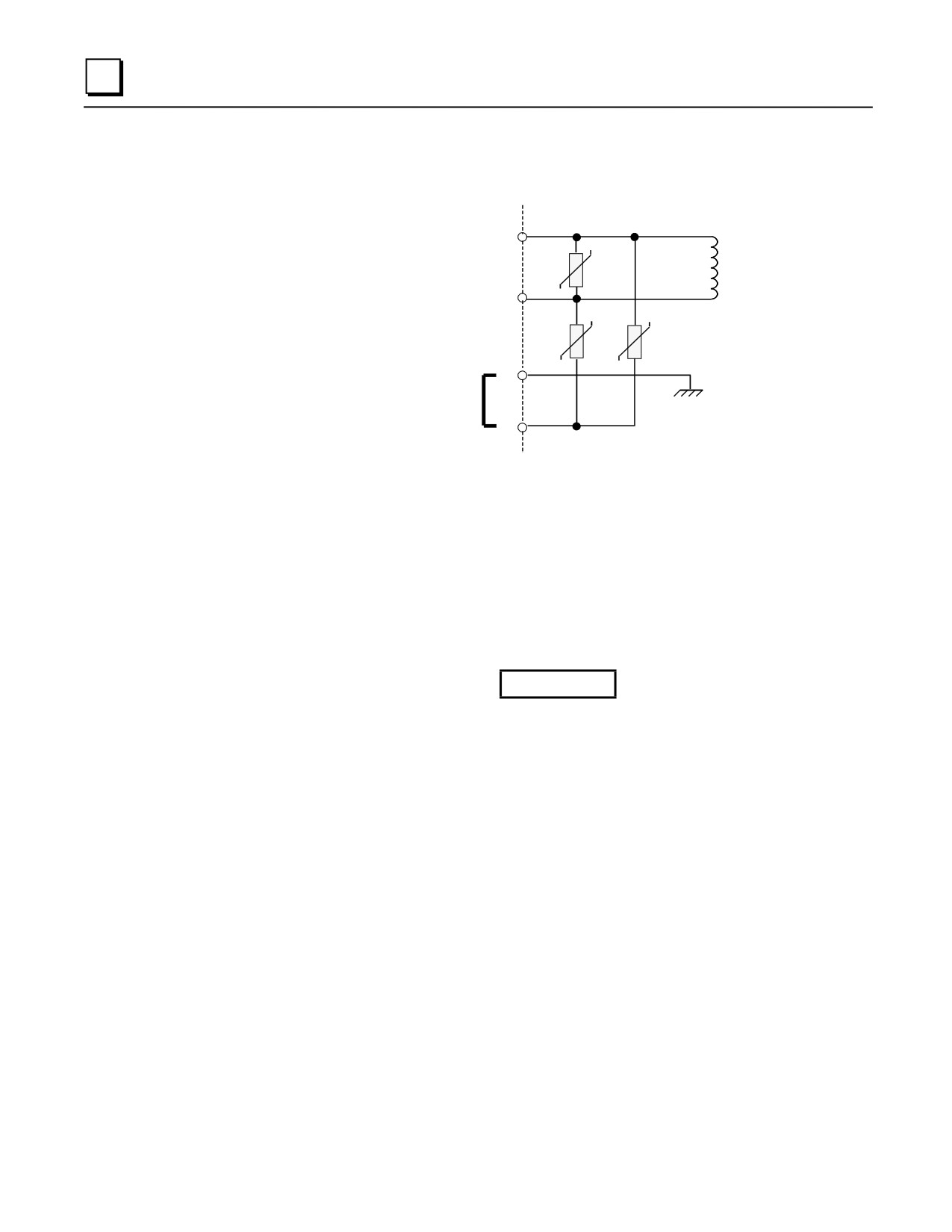
Input Overvoltage Protection Devices
This information applies to all Series 90-30 power supplies except IC693PWR322
and IC693PWR328. The overvoltage protection devices for this power supply are
connected internally to pin 4 on the user terminal strip. This pin is normally connected to
frame ground (pin 3) with the supplied jumper strap which is installed at the factory. If
overvoltage protection is not required or is supplied upstream, this feature can be disabled
by removing the jumper strap from pins 3 and 4.
GFK-0356Q
Chapter 4 Power Supplies
4-5
4
If you want to Hi-pot test this supply, overvoltage protection must be disabled during the
test by removing the terminal strip jumper strap. Re-enable overvoltage protection after
testing by reinstalling the strap.
1
2
3
Frame Ground
Jumper Strap Connects
Overvoltage Protection
Devices to Frame Ground
4
Screw Terminals
on Terminal Board
Figure 4-3. Overvoltage Protection Devices and Jumper Strap
Isolated 24 VDC Supply Output Connections
The bottom two terminals of the power supply terminal strip provide connections to the
Isolated +24 volt DC output which can be used to provide power for external circuits
(within power limitations of the supply).
Caution
If the Isolated 24 VDC supply is overloaded or shorted, the
Programmable Logic Controller will stop operation.
4-6
Series 90-30 PLC Installation and Hardware Manual - August 2002
GFK-0356Q
4
DC Input Only Power Supplies
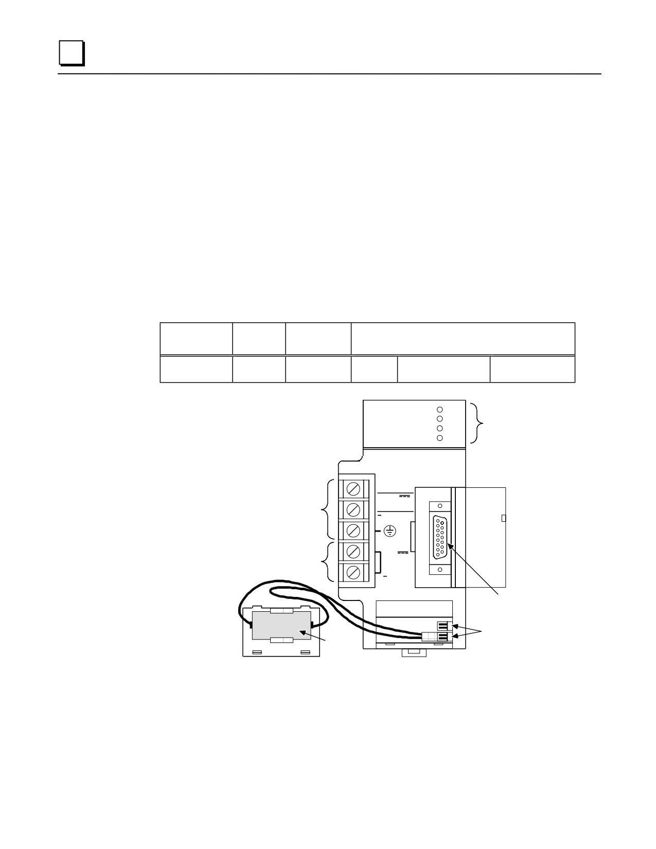
IC693PWR322 Standard Power Supply, 24/48 VDC Input
The IC693PWR322 is a 30 watt output power supply designed for 24 VDC or 48 VDC nominal
inputs. It will accept an input voltage range from 18 VDC to 56 VDC. Although it is capable of
maintaining all outputs within specifications with input voltages as low as 18 VDC, it will not start
with initial input voltages of less than 21 VDC. This power supply provides the following outputs:
■
+5 VDC output.
■
+24 VDC Relay power output which provides power to circuits on Series 90-30 Output Relay
modules.
■ Isolated +24VDC, which is used internally by some modules, can also be used to provide
external power for 24VDC Input modules.
The load capacity for each output of this power supply is shown in the following table.
Table 4-6. IC693PWR322 Power Supply Capacities
Catalog
Load
Number
Capacity
Input
Output Capacities (Voltage/Power *)
IC693PWR322
30 Watts
24 or 48 VDC
+5 VDC
+24 VDC Isolated 20
+24 VDC Relay 15
15 watts
watts
watts
* Total of all outputs combined cannot exceed 30 watts.
PWR
IC693PWR322
GE Fanuc
OK
SYSTEM
STATUS
Series 90-30
RUN
INDICATORS
BATT
PROGRAMMABLE
CONTROLLER
STANDARD
POWER SUPPLY
PROGRAMMABLE CONTROLLER
+
INPUT
CONNECTIONS
FOR
24/48 VDC
DC POWER
50 WATT
SOURCE
INTERNAL POWER
SOURCE FOR
+
MODULES REQUIRING
24 VDC
24VDC
OUTPUT
0.8A MAX.
RS-485
B
COMPATIBLE
A
SERIAL PORT
T
T
E
BATTERY
R
CONNECTORS
LITHIUM
Y
BACK-UP
BATTERY
Figure 4-4. Series 90-30 24/48 VDC Input Power Supply - IC693PWR322
GFK-0356Q
Chapter 4 Power Supplies
4-7

4
Table 4-7. Specifications for IC693PWR322 Power Supply
Nominal Rated Voltage
24 or 48 VDC
Input Voltage Range
Start
21 to 56 VDC
Run
18 to 56 VDC
Input Power
50 watts maximum at full load
Inrush Current
4A peak, 100 ms maximum
Output Power
5 VDC: 15 watts maximum
24 VDC Relay: 15 watts maximum
24 VDC Isolated: 20 watts maximum
NOTE: 30 watts maximum total (all three outputs)
Output Voltage
5 VDC: 5.0 VDC to 5.2 VDC (5.1 VDC nominal)
24 VDC Relay:
24 to 28 VDC
24 VDC Isolated: 21.5 VDC to 28 VDC
Protective Limits
Overvoltage:
5 VDC output: 6.4 to 7 V
Overcurrent;
5 VDC output: 4 A maximum
Holdup Time:
14 ms minimum
Standards
Refer to data sheet, GFK-0867B, or later version for
product standards, and general specifications.
Calculating Input Power Requirements for IC693PWR322
The following graph is a typical 24/48 VDC power supply efficiency curve. A basic procedure for
determining efficiency of the 24/48 VDC power supply follows the figure.
50
45W
40
AVERAGE
30
INPUT
POWER
(WATTS)
20
10
5
10
15
20
25
30
TOTAL OUTPUT POWER (WATTS)
Figure 4-5. Typical Efficiency Curve for 24/48 VDC Power Supply
Note
Start-up surge at full load is 4 amps for 250 milliseconds (maximum).
4-8
Series 90-30 PLC Installation and Hardware Manual - August 2002
GFK-0356Q
4
Input Power/Current Calculation
■ Determine total output load from typical specifications listed for individual modules in
Chapters 2 and 3.
■ Use the graph to determine average input power.
■ Divide the input power by the operating source voltage to determine the input current
requirements.
■ Use the lowest input voltage to determine the maximum input current.
■ Allow for start-up surge current requirements.
■ Allow margins (10% to 20%) for variations.
GFK-0356Q
Chapter 4 Power Supplies
4-9
4
IC693PWR328 Standard Power Supply, 48 VDC Input
The IC693PWR328 is a 30 watt output power supply designed for 48 VDC nominal input. It will
accept an input voltage range from 38 VDC to 56 VDC. This power supply provides the following
outputs:
■
+5 VDC output.
■
+24 VDC Relay power output which provides power to circuits on Series 90-30 Output Relay
modules.
■ Isolated +24 VDC, which is used internally by some modules, can also be used to provide
external power for 24 VDC Input modules.
The load capacity for each output of this power supply is shown in the following table.
Table 4-8. IC693PWR328 Power Supply Capacities
Catalog
Load
Number
Capacity
Input
Output Capacities (Voltage/Power *)
IC693PWR328
30 Watts
48 VDC
+5 VDC
+24 VDC Isolated 20
+24 VDC Relay 15
15 watts
watts
watts
* Total of all outputs combined cannot exceed 30 watts.
PWR
IC693PWR328
GE Fanuc
OK
SYSTEM
STATUS
Series 90-30
RUN
INDICATORS
BATT
PROGRAMMABLE
CONTROLLER
STANDARD
POWER SUPPLY
PROGRAMABLE CONTROLLER
+
INPUT
CONNECTIONS
FOR
48 VDC
DC POWER
50 WATT
SOURCE
INTERNAL POWER
SOURCE FOR
+
MODULES REQUIRING
24 VDC
24VDC
OUTPUT
0.8A MAX.
RS-485
B
COMPATIBLE
A
SERIAL PORT
T
T
E
BATTERY
R
CONNECTORS
LITHIUM
Y
BACK-UP
BATTERY
Figure 4-6. Series 90-30 48 VDC Input Power Supply - IC693PWR328
4-10
Series 90-30 PLC Installation and Hardware Manual - August 2002
GFK-0356Q

4
Table 4-9. Specifications for IC693PWR328 Power Supply
Nominal Rated Voltage
48 VDC
Input Voltage Range
38 to 56 VDC
Input Power
50 watts maximum at full load
Inrush Current
4A peak, 100 ms maximum
Output Power
5 VDC: 15 watts maximum
24 VDC Relay: 15 watts maximum
24 VDC Isolated: 20 watts maximum
NOTE: 30 watts maximum total (all three outputs)
Output Voltage
5 VDC: 5.0 VDC to 5.2 VDC (5.1 VDC nominal)
24 VDC Relay: 24 to 28 VDC
24 VDC Isolated:
21.5 VDC to 28 VDC
Protective Limits
Overvoltage:
5 VDC output: 6.4 to 7 V
Overcurrent;
5 VDC output: 4 A maximum
Holdup Time:
14 ms minimum
Standards
Refer to data sheet, GFK-0867B, or later version for
product standards, and general specifications.
Calculating Input Power Requirements for IC693PWR328
The following graph is a typical 48 VDC power supply efficiency curve. A basic procedure for
determining efficiency of the 48 VDC power supply follows the figure.
50
45W
40
AVERAGE
30
INPUT
POWER
(WATTS)
20
10
5
10
15
20
25
30
TOTAL OUTPUT POWER (WATTS)
Figure 4-7. Typical Efficiency Curve for IC693PWR328 Power Supply
Note
Start-up surge at full load is 4 amps for 250 milliseconds (maximum).
GFK-0356Q
Chapter 4 Power Supplies
4-11
4
Input Power/Current Calculation for IC693PWR328 Power Supply
■ Determine total output load from typical specifications listed for individual modules in
Chapter 12.
■ Use the graph to determine average input power.
■ Divide the input power by the operating source voltage to determine the input current
requirements.
■ Use the lowest input voltage to determine the maximum input current.
■ Allow for start-up surge current requirements.
■ Allow margins (10% to 20%) for variations.
4-12
Series 90-30 PLC Installation and Hardware Manual - August 2002
GFK-0356Q
4
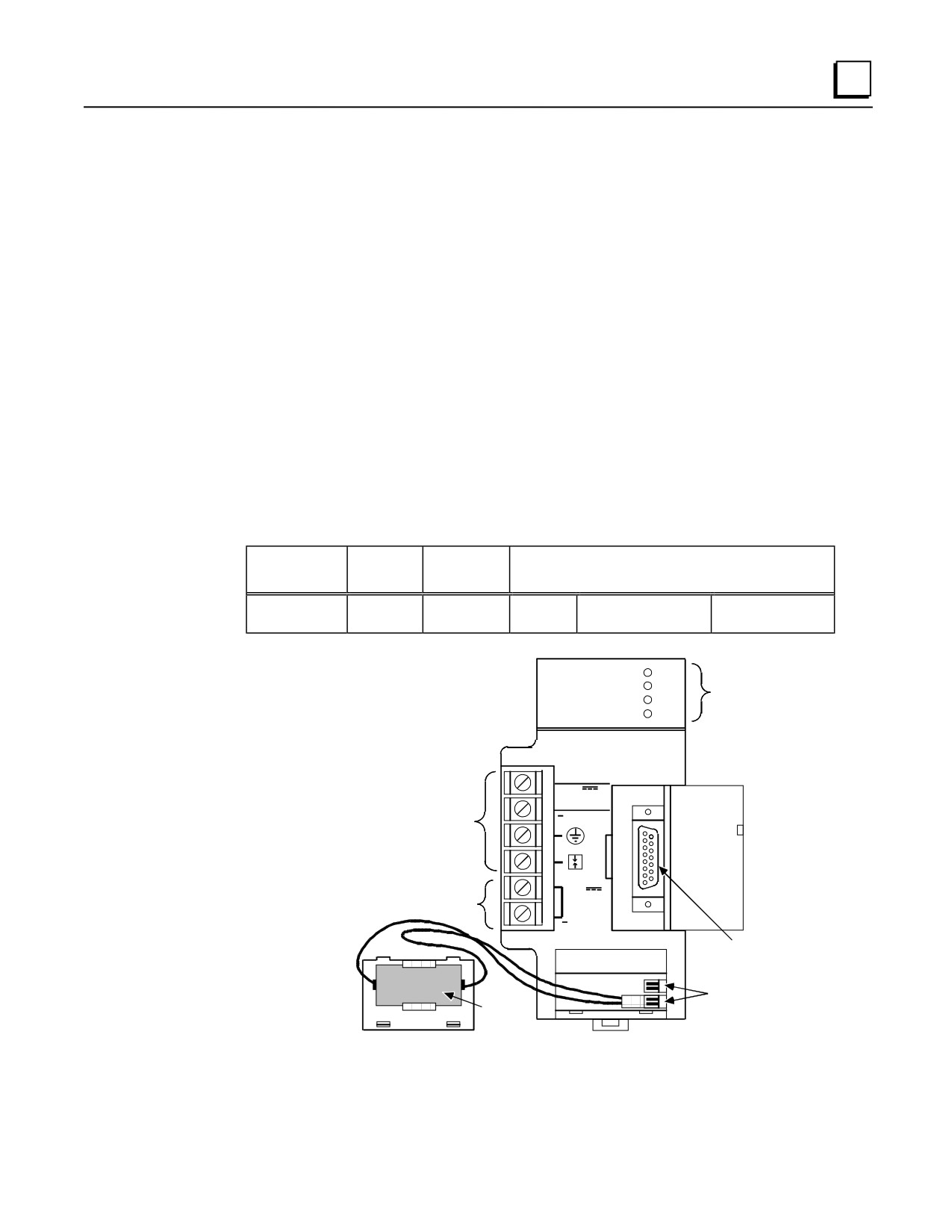
IC693PWR331 High Capacity Power Supply, 24 VDC Input
The Series 90-30 DC input High Capacity power supply (IC693PWR331) is a 30 watt wide range
supply designed for 24 VDC nominal inputs. For applications requiring greater +5V current
capacity than is available with the standard supply, this supply allows all 30 watts to be consumed
from the +5 V output. It will accept an input voltage range from 12 VDC to 30 VDC. Although it
is capable of maintaining all outputs within specifications with input voltages as low as 12 VDC, it
will not start with initial input voltages of less than 18 VDC. This power supply provides the
following outputs:
■
+5 VDC output.
■
+24 VDC Relay power output which provides power to circuits on Series 90-30 Output Relay
modules.
■ Isolated +24 VDC, which is used internally by some modules, can also be used to provide
external power for 24 VDC Input modules.
The load capacity for each output of this power supply is shown in the following table.
Table 4-10. IC693PWR331 Power Supply Capacities
Catalog
Load
Number
Capacity
Input
Output Capacities (Voltage/Power *)
IC693PWR331
30 Watts
12 to 30
+5 VDC
+24 VDC Isolated 20
+24 VDC Relay 15
VDC
30 watts
watts
watts
* Total of all outputs combined cannot exceed 30 watts.
PWR
IC693PWR331
SYSTEM
GE Fanuc
OK
STATUS
Series 90-30
RUN
INDICATORS
BATT
HIGH CAPACITY
POWER SUPPLY
PROGRAMMABL CONTROLLER
E
+ INPUT
24 VDC
50 WATT
CONNECTIONS FOR
DC POWER SOURCE
+
INTERNAL POWER SOURCE
24 VDC
MODULES REQUIRING 24VDC
OUTPUT
0.8A MAX.
RS-485
B
COMPATIBLE
A
SERIAL PORT
T
T
E
BATTERY
R
CONNECTORS
LITHIUM
BACK-UP
Y
BATTERY
Figure 4-8. Series 90-30 24 VDC Input High Capacity Power Supply - IC693PWR331
GFK-0356Q
Chapter 4 Power Supplies
4-13

4
Table 4-11. Specifications for IC693PWR331 Power Supply
Nominal Rated Voltage
24 VDC
Input Voltage Range
Start
18 to 30 VDC
Run
12 to 30 VDC
Input Power
50 watts maximum at full load
Inrush Current
Output Power
5 VDC: 30 watts maximum **
24 VDC Relay: 15 watts maximum
24 VDC Isolated: 20 watts maximum
NOTE: 30 watts maximum total (all three outputs)
Output Voltage
5 VDC:
5.0 VDC to 5.2 VDC (5.1 VDC nominal)
24 VDC Relay: 19.2 to 28.8 VDC
24 VDC Isolated: 19.2 VDC to 28.8 VDC
Protective Limits
Overvoltage:
5 VDC output: 6.4 to 7 V
Overcurrent;
5 VDC output: 7 A maximum
Holdup Time:
10 ms minimum
Standards
Refer to data sheet, GFK-0867B, or later version for
product standards, and general specifications.
* Dependent on installation and power supply impedance characteristics.
** Derate per Figure 2-22 at ambient temperatures above 50°C (122°F).
Current Derating for Higher Temperatures
6.1
6.0
5.8
5.6
5.4
5.2
5 VDC
5.0
CURRENT
4.8
4.6
4.4
4.2
4.0
0
10
20
30
40
50
55
60
AMBIENT TEMPERATURE (°C)
Figure 4-9. 5 VDC Current Output Derating for Temperatures above 50°C (122°F)
4-14
Series 90-30 PLC Installation and Hardware Manual - August 2002
GFK-0356Q
4
Calculating Input Power Requirements for IC693PWR331
Use the following procedure to determine input power requirements for the 24 VDC High Capacity
Power Supply:
■ Determine total output power load from typical specifications listed for
individual modules at the end of this chapter.
■ Multiply the output power by 1.5 to determine the input power value.
■ Divide the input power value by the operating source voltage to determine the
input current requirements
■ Use the lowest input voltage to determine the maximum input current
■ Allow for start-up surge current requirements
■ Allow margins (10% to 20%) for variations
Field Wiring Connections to the DC Input-Only Power Supplies
DC Power Source Connections
The + and - wires from the DC power source connect to the top two terminals on the
terminal strip. The + wire should be connected to the top terminal screw, and the - wire to
the second screw (counting from the top down). The ground connection connects to the
third screw. This connection scheme is clearly marked on the front of these power
supplies.
Isolated 24 VDC Supply Output Connections
The bottom two terminals of the power supply terminal strip provide connections to the
Isolated +24 volt DC output which can be used to provide power for external circuits
(within power limitations of the supply).
Caution
If the Isolated 24 VDC supply is overloaded or shorted, the
Programmable Logic Controller will stop operation.
GFK-0356Q
Chapter 4 Power Supplies
4-15
4
Common Series 90-30 Power Supply Features
Status Indicator Lights on all Power Supplies
Four LEDs are located on the upper right front of the power supply faceplate. The purpose of these
LEDs is as follows:
PWR
The top green LED, labeled PWR, provides an indication of the operating state of the
power supply. The LED is ON when the power supply has a correct source of power and
is operating properly, and OFF when a power supply fault occurs or power is not applied.
OK
The second green LED, labeled OK, is steady ON if the PLC is operating properly, and
OFF if a problem is detected by the PLC.
RUN
The third green LED, labeled RUN, is steady ON when the PLC is in the RUN mode.
BATT
The bottom red LED, labeled BATT, will be ON if the memory backup battery voltage is
too low to maintain the memory under a loss of power condition; otherwise it remains
OFF. If this LED is ON, the Lithium battery must be replaced before removing power
from the rack, or PLC memory may be lost.
Input Overvoltage Protection Devices
This information applies to all Series 90-30 power supplies except IC693PWR322
and IC693PWR328. The overvoltage protection devices for this power supply are
connected internally to pin 4 on the user terminal strip. This pin is normally connected to
frame ground (pin 3) with the supplied jumper strap which is installed at the factory. If
overvoltage protection is not required or is supplied upstream, this feature can be disabled
by removing the jumper strap from pins 3 and 4.
If you want to Hi-pot test this supply, overvoltage protection must be disabled during the
test by removing the terminal strip jumper strap. Re-enable overvoltage protection after
testing by reinstalling the strap.
4-16
Series 90-30 PLC Installation and Hardware Manual - August 2002
GFK-0356Q
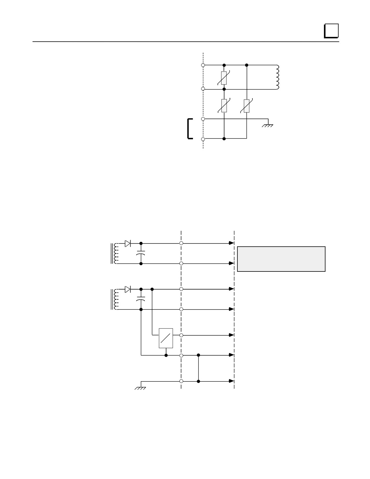
4
1
2
3
Frame Ground
Jumper Strap Connects
Overvoltage Protection
Devices to Frame Ground
4
Screw Terminals
on Terminal Board
Figure 4-10. Overvoltage Protection Devices and Jumper Strap
Output Voltage Connections to Backplane (All Supplies)
The following figure illustrates how these three output voltages are connected internally to the
backplane on the baseplate. The voltage and power required by modules installed on the baseplate
is supplied through the baseplate connectors.
POWER SUPPLY
BACKPLANE
USE/COMMENTS
USED INTERNALLY ON ANALOG INPUT,
I 24V
ANALOG OUTPUT, AND DC INPUT MODULES.
ALSO AVAILABLE ON EXTERNAL
TERMINALS ON DC INPUT MODULES AND
ON FRONT OF POWER SUPPLY FOR
IGND
USER APPLICATIONS.
R24V
USED INTERNALLY ON
RELAY OUTPUTS
RGND
SINGLE
POINT
CONNECTION
P5V
DC
DC
USED INTERNALLY ON CPU,
INPUTS, OUTPUTS, ETC.
LGND
2 POINT
CONNECTION
FGND
EXTERNAL CONNECTION
TO EARTH GROUND.
Figure 4-11. Interconnection of Power Supplies
GFK-0356Q
Chapter 4 Power Supplies
4-17
4
Overcurrent Protection (all Supplies)
The 5V logic output is electronically limited to 3.5 amps (7 amps for high capacity supplies). An
overload (including short circuits) is sensed internally and causes the supply to shut down. The
supply will continually try to restart until the overload is removed. An internal fuse in the input
line is provided as a backup. The supply will usually shut down before the fuse blows. The fuse
also protects against internal supply faults.
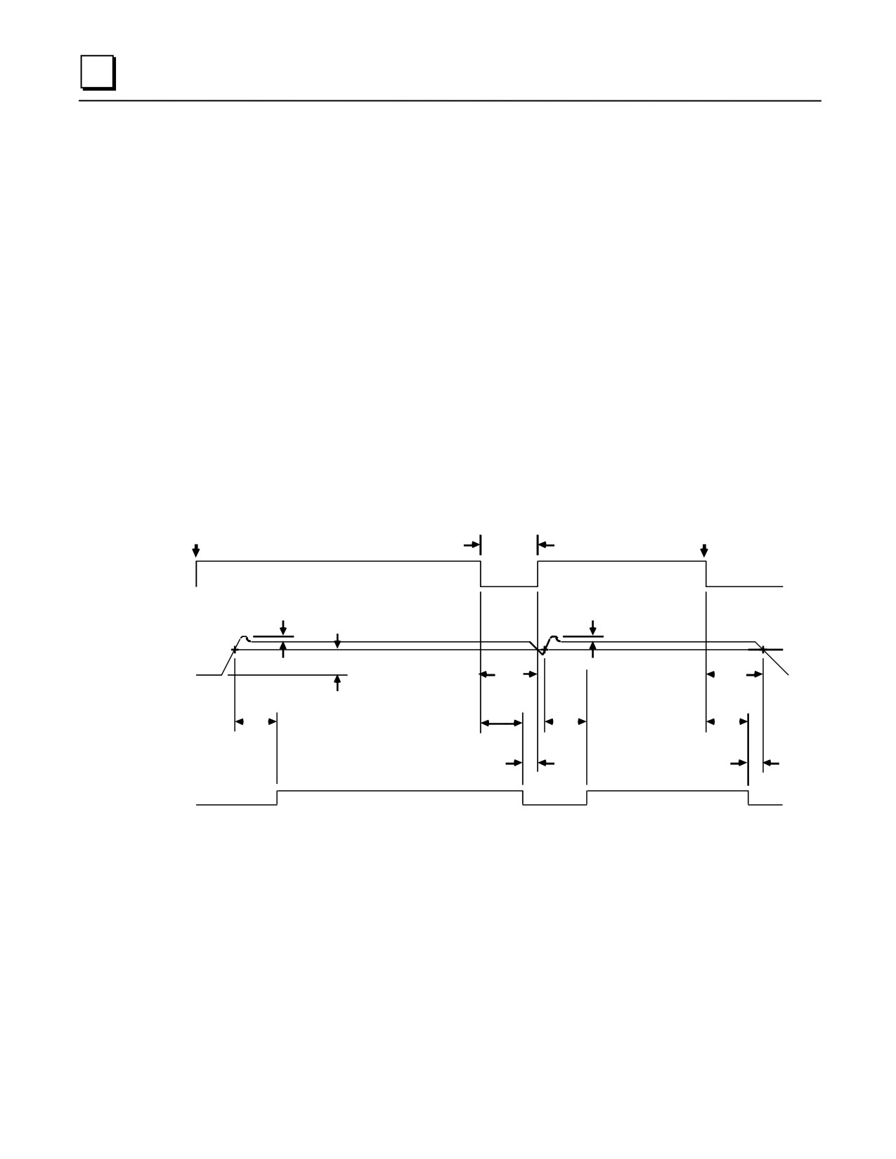
Timing Diagram
The timing diagram below shows the relationship of the DC input to the DC outputs and to the
Power Supply OK signal (PSOK) generated by the power supply. When power is first applied, the
PSOK signal goes false. This line remains false for a minimum of 20 msec after the +5V bus is
within specifications, then it becomes true.
If input power is interrupted, the +5V bus will remain within specifications and PSOK will remain
true a minimum of 10 milliseconds. PSOK then goes false. The +5V bus will remain within
specifications for an additional 4 milliseconds minimum to allow an orderly shutdown of the
system.
INPUT
INPUT
POWER
MOMENTARY
POWER
ON
POWER
OFF
LOSS
VOLTAGE
VOLTAGE
OVERSHOOT
OVERSHOOT
5% (MAX)
5% (MAX)
+5V OUTPUT
(5.1V TYP.)
97% (MIN)
HOLD
HOLD
UP
UP
TIME*
TIME
20MS
20MS
10MS
(MIN)
(MIN)
(MIN)
4MS
4MS
(MIN)
(MIN)
PSOK
*HOLD-UP TIME:
20 ms, minimum for IC693PWR321/330
14 ms, minimum for IC693PWR322
10 ms, minimum for IC693PWR331/332
Figure 4-12. Timing Diagram for all Series 90-30 Power Supplies
4-18
Series 90-30 PLC Installation and Hardware Manual - August 2002
GFK-0356Q
4
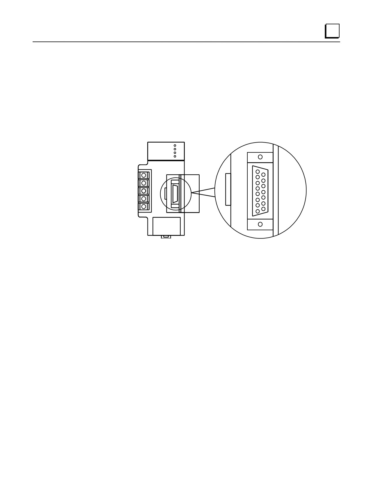
CPU Serial Port Connector on Power Supply (All Supplies)
A 15-pin D-type female connector, accessed by opening the hinged door on the right front of the
power supply, provides the connection to a CPU serial port which is used to connect to:
■ A programmer (usually a personal computer) running GE Fanuc PLC programming software.
■ The GE Fanuc Hand-Held Programmer.
■ Other serial devices.
a43832
RS-485
COMPATIBLE
SERIAL PORT
Figure 4-13. Serial Port Connector
■ The serial port connector is only functional in a power supply that is installed in a baseplate
that also contains the CPU. The serial port is not functional on a power supply that is installed
in an expansion or remote baseplate.
■ Any device connected to the serial port that uses +5 VDC power from the Series 90-30 power
supply must be included in the calculation for maximum power consumption (see “Power
Supply Loading Calculations” in Chapter 12).
CPU Serial Port Information
The serial port connector on the power supply accesses the CPU serial port, which is a feature of all
Series 90-30 CPUs. See Chapter 5, “CPUs” for information on this serial port.
GFK-0356Q
Chapter 4 Power Supplies
4-19
4
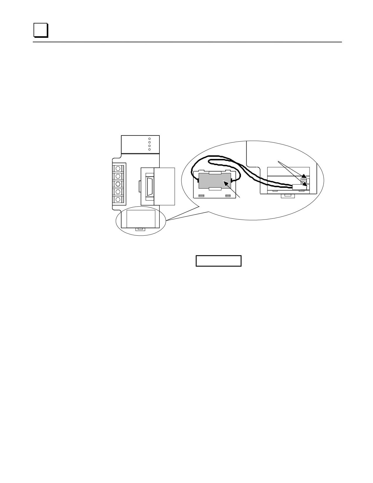
Backup Battery for RAM Memory (All Supplies)
The long-life Lithium battery (IC693ACC301) used to maintain the contents of the CMOS RAM
memory in the CPU is accessed by removing the cover plate located at the bottom of the power
supply faceplate. This battery is mounted on a plastic clip attached to the inside of this cover.
The battery is wired to a small Berg female connector that connects to either of the two Berg male
connectors mounted on the Power Supply printed circuit board. This battery can be replaced with
power applied to the PLC.
BATTERY
CONNECTORS
LITHIUM
BACK-UP
BATTERY
Figure 4-14. Backup Battery for RAM Memory
Caution
If a Low Battery Warning (BATT LED turns ON) occurs, replace the
battery located in the power supply before removing power from the rack.
Otherwise, there is a possibility that data will be corrupted or the
application program will be cleared from memory.
Additional Battery Information
For additional information on the memory backup battery, see the chapter, “Memory Backup and
Backup Battery.”
4-20
Series 90-30 PLC Installation and Hardware Manual - August 2002
GFK-0356Q
Chapter
CPUs
5
CPU Types for Series 90-30 PLCs
There are numerous CPU models available for the Series 90-30 PLC which differ in speed, I/O
capacity, size of user memory, and advanced features. This variety of models gives a system
designer considerable flexibility in choosing the one best suited to the system being designed.
There are two basic types of CPUs, Embedded and Modular. The embedded types fulfill the need
for a good low cost PLC, but lack the power, expandability, and versatility of the modular systems.
In the embedded types, the CPU is built into the baseplate. In the modular types, the CPU is
contained inside a plug-in module.
Embedded CPUs
The embedded CPUs are part of an embedded CPU baseplate. In these products, the CPU and
memory integrated circuit chips are soldered to the backplane board of the baseplate. This chapter
discusses the CPU features of these products. Details about the baseplate features are located in
Chapter 2. There are three different embedded CPUs: Model 311 (IC693CPU311), Model 313
(IC693CPU313), and Model 323 (IC693CPU323). The embedded CPUs have the following basic
features:
■ The CPU type cannot be changed. It is soldered to the backplane board in the baseplate.
■ They do not support the use of Expansion or Remote racks, so an embedded CPU baseplate
does not have an expansion connector like the modular baseplates do. This means that if you
have an application that requires more than 10 modules, you will have to use a modular CPU
system.
■ The models 311 and 313 are 5-slot baseplates, and the model 323 is a 10-slot baseplate. Since
they do not require a plug-in CPU module, all numbered slots, including Slot 1, can be used
for I/O or Option modules.
■ The memory back-up battery is located in the Power Supply module; so if the Power Supply is
unplugged from the baseplate, the battery will be disconnected from the memory circuits,
which are located on the backplane circuit board. However, the backplane circuit board
contains a high value capacitor, called a ”super capacitor,” that can store enough charge to
maintain the memory circuits for a short period of time if the Power Supply is removed or its
battery is disconnected. See the section “Super Capacitor Memory Backup” in Chapter 6.
■ These CPUs do not have a time-of-day (TOD) clock.
GFK-0356Q
5-1
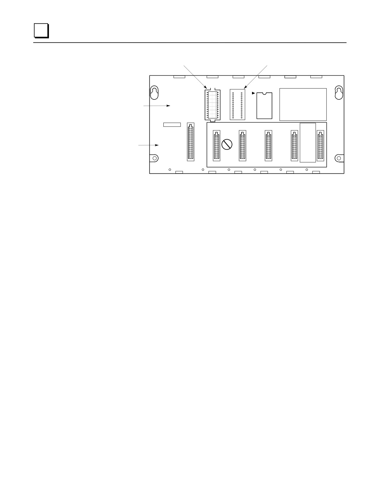
5
a44563A
Replaceable System (firmware) PROM
Socket for Optional Program PROM
SYSTEM
PROGRA
PROM
PROM
PROGRAMMABL
1
CONTROLLER
Description Label
BASE 5-
Says "With CPU"
WITH CPU
CAUTION
NON-CPU SLOTS
USER
AND REGISTER
VALUES MAY BE
Memory Backup
LOST IF POWER
C
Warning Label
SUPPLY IS
P
REMOVED FOR
U
LONGER THAN
1 HOUR
POWER
I/O-1
I/O-2
I/O-3
I/O-4
I/O-5
SUPPLY
Figure 5-1. Models 311 and 313 (5-Slot) Embedded CPU Baseplates
Modular CPUs
The modular CPUs consist of a CPU, memory, and associated integrated circuit chips soldered to
circuit board which is mounted in a plug-in module. The modular CPUs include the model CPU331
and higher. The modular CPUs have the following basic features:
■ A CPU module must be installed in Slot 1 of a modular CPU baseplate. Slot 1 is a unique size
and type that only fits a CPU module (or special Option modules). Slot 1 is labeled CPU/1.
Details on modular CPU baseplates are located in Chapter 2.
■ Modular CPUs support expansion and remote baseplates, so A 25-pin D-type female
expansion connector is located at the right end of the CPU baseplate for connection to an
expansion or remote baseplate.
■ Since the CPU is modular, it can readily be replaced or changed to a different type if desired.
■ Only one CPU is allowed per system, and it must be mounted in a CPU baseplate. If more
than one baseplate is used in a system, the additional ones must be either expansion or remote
types that do not contain a CPU.
■ A modular CPU baseplate is always assigned, by default, Rack Number 0.
■ All have a time-of-day (TOD) clock.
5-2
Series 90-30 PLC Installation and Hardware Manual - August 2002
GFK-0356Q

5
PROGRAMMABLE
CONTROLLER
BASE 5-SLOT
E
X
P
A
CAUTION
NON-CPU SLOTS
N
I/O Bus
Memory Backup
USER PROGRAMAND REGISTER
S
VALUES MAY BE
I
Expansion
Warning Label
LOST IF POWER
O
Connector
SUPPLY IS
N
REMOVED FOR
CP
LONGER THAN
U
1 HOUR
I/O-2
I/O-3
I/O-4
I/O-5
S
PPLY
CPU/1
CPU Slot (Slot 1)
Figure 5-2. IC693CHS397 5-Slot Modular CPU Baseplate
General CPU Features
Microprocessor
The microprocessor type varies by the CPU model:
■
80188 microprocessor for CPU models 311/313/323/331
■
80C188XL microprocessor for CPU models 340/341
■
80386EX microprocessor for CPU models 350-364
■
586 microprocessor for CPU model 374
The microprocessor provides all fundamental sweep and operation control, and execution of all
non-boolean (as used here, the term boolean refers to discrete logic such as contacts and coils)
functions. Boolean functions in the modular CPUs are handled by a dedicated VLSI (Very Large
Scale Integration) Instruction Sequencer Coprocessor (ISCP). All Series 90-30 CPUs use RAM
working memory.
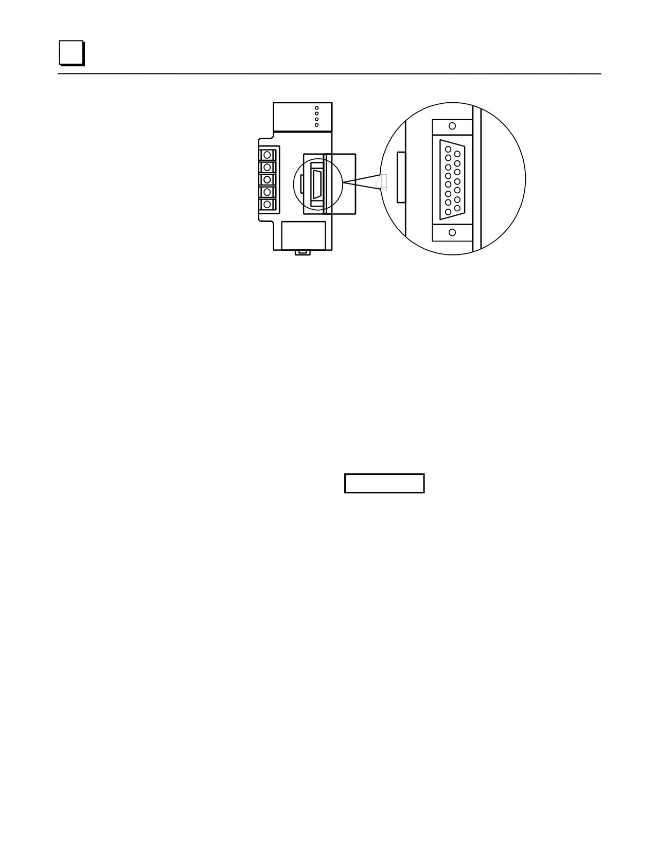
CPU Serial Port (Connector on Power Supply)
A 15-pin D-type female connector, accessed by opening the hinged door on the right front of the
power supply, provides the connection to a CPU serial port which is used to connect to:
■ a programmer (usually a personal computer) running GE Fanuc PLC programming software.
The IC690ACC901 Miniconverter/cable kit is a convenient way to access this port. See
Appendix D for details.
■ the IC693PRG300 GE Fanuc Hand-Held Programmer (CPU374 does not support the HHP.)
See Chapter 11 for details.
■ the IC200ACC003 EZ Program Store device. See GFK-1811 for details. (CPU374 only)
■ other serial devices.
GFK-0356Q
Chapter 5 CPUs
5-3
5
RS-485
COMPATIBLE
SERIAL PORT
Figure 5-3. CPU Serial Port Connector on Power Supply
■ This serial port is RS-485 compatible, and uses the GE Fanuc SNP (Series Ninety Protocol)
protocol (slave only). Breakfree SNP became the default protocol on all serial ports on the
Series 90-30 CPUs, starting with firmware release 9.00 for CPUs 350-364, and firmware
release 8.20 for CPUs 311-341. For details, see page 5-13.
■ The serial port connector is only functional in a power supply that is installed in a baseplate
that also contains the CPU. It is not functional on a power supply that is installed in an
expansion or remote baseplate.
■ Any device connected to the serial port that uses +5 VDC power from the Series 90-30 power
supply must be included in the calculation for maximum power consumption (see the heading
“Power Supply Loading Calculations” in Chapter 12).
■ All Series 90-30 CPUs have this serial port arrangement. The 351, 352, and 363 CPUs have
additional serial ports, described in a later section of this chapter.
Caution
Care must be taken that common mode voltage specifications are met for
connections to this serial port. Common mode conditions that exceed those
specified will result in errors in transmission and/or damage to Series 90
PLC components. Common mode specifications are discussed in
Appendix A. When the common mode voltage specification is exceeded, a
port isolator such as the GE Fanuc IC690ACC903 must be used. See
Appendix G for details on this port isolator.
Memory Volatility
The term volatility refers to the issue of whether or not a certain memory type retains or loses its
contents (data) when power is removed from it.
■ Volatile memory - memory that loses its contents when power is removed. RAM memory is
inherently volatile. Therefore, when the PLC is turned off, a backup battery is necessary if
data loss in RAM memory is to be prevented.
■ Non-volatile memory - memory that retains its contents when power is removed. The various
types of PROM (Programmable Read-Only Memory) memory are non-volatile.
5-4
Series 90-30 PLC Installation and Hardware Manual - August 2002
GFK-0356Q
5
RAM Memory
Every Series 90-30 CPU uses RAM memory for its ”working memory.” The RAM chips used are
of the CMOS type. CMOS RAM is an acronym for Complimentary Metal-Oxide Semiconductor,
Random Access Memory. CMOS RAM is a relatively fast, low power memory that can be easily
examined (read) and changed (written to).
In the embedded CPU models, RAM memory is mounted on the backplane board. In the modular
CPU models, RAM memory is mounted inside the CPU module. A backup battery is usually used
to preserve the contents of RAM memory when power is off.
RAM Memory Backup/Backup Battery Information
Please see Chapter 6 for the following information:
■ RAM memory backup recommendations.
■ Backup battery information such as estimated life, replacing, determining battery age using
date codes, etc.
■ Running without a backup battery.
■ Low battery warning methods.
Programmable Read-Only Memory (PROM) Types
There are three types of PROM devices used in Series 90-30 CPUs:
EPROM: Erasable Programmable Read-Only Memory. It is a plug-in integrated circuit memory
device that can be erased with an ultraviolet light. EPROMs can be read when installed in the PLC,
however in order to write new data to them, they must be removed from the PLC and written to
using an external PROM burning device.
EEPROM: Electrically Erasable Programmable Read-Only Memory. It is a plug-in integrated
circuit memory device that can be erased and written to while installed in the PLC.
Flash Memory: A variation of the EEPROM type memory. It also is an integrated circuit device
that can be erased and written to while installed in the PLC. One advantage of CPUs having flash
memory storage of firmware, is that firmware can be updated by writing from a Personal Computer
through a PLC serial port to flash memory. No modules have to be removed for flash firmware
upgrade.
Uses of PROM devices in the 90-30 CPUs
PROM-type devices are used in two ways in the 90-30 CPUs:
■ To store CPU firmware
■ To store user data, which consists of program, configuration, and register data.
The following table shows the types of PROM devices each CPU uses.
GFK-0356Q
Chapter 5 CPUs
5-5

5
Table 5-1. CPU Firmware and PROM Configurations
Firmware
EPROM
EEPROM
Flash
CPU
(standard)
(for user memory)
(for user memory)
(for user memory)
CPU311
EPROM
Optional
Optional
N/A
CPU313
EPROM
Optional
Optional
N/A
CPU323
EPROM
Optional
Optional
N/A
CPU331
EPROM
Optional
Optional
N/A
CPU340
EPROM
N/A
N/A
Optional
CPU341
EPROM
*Optional
* Optional
*Optional
CPU350
Flash
N/A
N/A
Standard
CPU351
Flash
N/A
N/A
Standard
CPU352
Flash
N/A
N/A
Standard
CPU360
Flash
N/A
N/A
Standard
CPU363
Flash
N/A
N/A
Standard
CPU364
Flash
N/A
N/A
Standard
CPU374
Flash
N/A
N/A
Standard
* Early versions of the CPU341 support optional EPROM and optional
EEPROM only. Starting with hardware version IC693CPU341-J and Firmware
version 4.61, only optional Flash is supported.
CPU Firmware
The CPU firmware contains the basic operating instructions for the PLC. Firmware is developed
by a GE Fanuc product engineering group. It is stored in either EPROM or Flash memory,
depending on the particular CPU.
CPU Firmware Upgrade (Update)
From time to time, new firmware is released. A new firmware version may contain support for
new features or improvements to existing features. Once a new version of CPU firmware is
released, all new CPU modules will be sold with that version. The Technical Support section of
the GE Fanuc Web site lists CPU revision histories, matching version numbers to associated
features. See Chapter 13 for information on the GE Fanuc Web site. Users who could benefit from
a new firmware release may choose to upgrade their CPU by installing new firmware. Upgrades
come in two formats, depending on the type of CPU to be upgraded. The ”CPU Firmware and
PROM Configuration” table in this chapter shows which type of firmware storage device each CPU
has. The two types are:
■ EPROM - For CPUs with firmware stored in EPROM, the upgrade is done by replacing the
CPU’s EPROM chips(s). The upgrade kit contains new EPROM chip(s), update labels, and
installation instructions. To upgrade the EPROM in an embedded CPU system, the module in
slot 1 must be unplugged to gain access to the PROM socket on the baseplate. In the case of a
modular CPU, the CPU must be unplugged and disassembled.
■ Flash - For CPUs with firmware stored in Flash, the upgrade is done by copying a new
firmware file to the CPU’s Flash memory. An upgrade kit may be purchased from GE Fanuc.
The upgrade kit contains the necessary files, update labels, and instructions. This method does
not require disassembling the module. The file downloading is done either through the port on
5-6
Series 90-30 PLC Installation and Hardware Manual - August 2002
GFK-0356Q
5
the power supply, or through a port on the front of the CPU module (if it has one). The
applicable method will be documented in your upgrade kit instructions. Downloadable
firmware upgrade files are also found in the Technical Support area of the GE Fanuc Web site.
See Chapter 13 for Web site information.
To order an upgrade kit, write down the full catalog number of your module from the module
identification label on the side of the module, determine your current firmware revision level, then
call your PLC distributor. If you are not sure what firmware version you currently have, see the
heading on the next page “Determining CPU Revision Levels (Versions).”
Flash Firmware Upgrade Procedure
The operating system firmware is updated by connecting a PC compatible computer to the
applicable PLC serial port and running the PC Loader software included with the firmware floppy
disk.
The computer used for this task should be an IBM AT compatible or better PC with a minimum
640K of RAM, one 3.5” or high density 5.25” floppy drive, MS-DOS version 3.3 or later, a hard
drive, and an RS-232 serial port. In addition, a miniconverter/serial cable is required. The following
miniconverter/serial cable kit is available:
■ IC690ACC901, Miniconverter Kit (RS-232/RS-485) with cable and 9-pin to 25-pin adapter.
(This product is documented in Appendix D.)
Determining CPU Revision Levels (Versions)
If you plan to make changes to your system, you will need to know if your CPU can support those
changes. The features and capabilities of your CPU are determined by its revision levels (hardware
and firmware). This section discusses methods that you can use to determine your CPU’s revision
levels and associated features and capabilities.
Direct Methods
■ Obtain the information from the Important Product Information (IPI) sheet that came with your
CPU. However, if your CPU firmware has been upgraded, the IPI will not indicate the current
revision level.
■ The surest way to determine a CPU’s firmware revision level is to read it from the CPU by
using your programmer. Your programmer must be connected to the PLC and be in Online or
Monitor mode, and the PLC must be powered up. For example, on the Logicmaster ”PLC
STATUS and CONTROL” screen is an item called ”SOFTWARE REVISION.” The data
displayed in that field (such as 6.04) is the firmware revision level. See the Logicmaster 90-30
Programming Software User’s Manual, GFK-0466 (or the user’s manual for the programming
software you use), for additional details.
Indirect Method
Check the catalog number printed on the module identification label on the side of the module.
On all Series 90-30 modules, this catalog number indicates the module’s revision level(s). For
some CPUs, the catalog number contains a single letter at the end to indicate the CPU’s overall
revision level. For example,
GFK-0356Q
Chapter 5 CPUs
5-7

5
IC693CPU341-J
This tells us that the module has a revision level J. Later CPU modules are produced with two
revision letters, such as:
IC693CPU351-EK
The first letter stands for the hardware revision level and the second for the firmware revision
level.
These letters can be cross-referenced to the firmware version. A revision history list for Series
90-30 products, including CPUs, can be found in the GE Fanuc web site technical support area
related features. Also, if you have access to the progression of IPIs that were issued for the
particular CPU (these are available on the GE Fanuc PLC InfoLink CD-ROM) you can find
the desired cross-reference. Of course, you can also contact your distributor or GE Fanuc for
help.
If your firmware has been upgraded in the past, a small label that comes in the upgrade kit
should be attached to the side of the module next to the module identification label to indicate
the current firmware revision level. However, the label could have been forgotten; so to be
sure, you may want to read the information from the CPU with a programmer as described in
the “Direct Method” above. On models with EPROM firmware, the firmware revision level
will also be printed on the EPROM.
EPROM and EEPROM User Program Storage Options
The Model 311, 313, 323, 331, and an earlier version of the Model 341 CPUs have a User PROM
option for storing user application programs, register data, and configuration data in non-volatile
memory. Application programs are usually developed in a CPU’s battery-backed RAM memory
and executed from this RAM memory. But, if additional program integrity, or operation of the
PLC without a battery is desired, an optional EEPROM or EPROM can be installed in a spare
socket (labeled PROGRAM PROM) on the embedded CPU baseplates or in a socket inside the
Model 331 CPU module (and inside the early versions of Model 341 CPU prior to hardware
version IC693CPU341-J and firmware release 4.61). The Model 331 CPU module (and the early
versions of Model 341) has a jumper labeled JP1 located next to the EEPROM/EPROM socket to
allow you to select either EEPROM or EPROM. These jumper positions are shown below.
Jumper
Selects
3 - 2
EEPROM
2 - 1
EPROM
Comparing EPROM and EEPROM Features
For one-time applications, an EEPROM is the more practical of the two. It can be created in the
PLC itself and doesn’t require any additional outside equipment. An EPROM is not as convenient
to create. It must be created outside the PLC using an EPROM burner. Because an EPROM is less
expensive than an EEPROM, if you need to reproduce multiple copies of a program to use on a
large number of identical controls, it may be cost effective to use EPROMs, especially if you
already have an EPROM burner.
5-8
Series 90-30 PLC Installation and Hardware Manual - August 2002
GFK-0356Q

5
Procedure for Creating an EPROM
1.
Install an EEPROM in the PROM socket of the PLC you will use to develop the application
program.
2.
Develop and debug the program in RAM memory, then write it to the EEPROM.
3.
Remove the EEPROM from the PLC and install it in the EPROM burner as a master to make
one or more EPROMs.
4.
Install the blank EPROM in the EPROM burner and copy the program on the EEPROM to the
blank EPROM.
5.
Install the EPROM in the PLC’s PROM socket, then copy its contents into RAM memory.
The EPROM then serves as an on-board backup to RAM memory.
Note: Your CPU can be configured to load the application program stored in the PROM device
automatically into RAM memory when the CPU is powered-up. See “Running Without a
Memory Backup Battery” in Chapter 6 for details.
Caution
If PROM is configured (on the CPU configuration screen) as the power-up
program source and a PROM device is not present in the PROM socket, or a
blank PROM is in the socket, on a power-up cycle, a blank program will be
copied into the CPU’s RAM memory and the program in RAM memory will
be lost. Always keep a backup copy of your current program files in case of
an emergency.
EEPROM and EPROM devices, listed in the following table, are available from GE Fanuc.
Table 5-2. EPROM and EEPROM Catalog Numbers
GE Fanuc
Third Party Source
Catalog Number
Description
Part Number
Vendor Part Number
IC693ACC305 (Qty 4)
28C256 EEPROM, 350ns
44A725999-000
XICOR X28C256P
XICOR X28C256P25
XICOR X28HC256P-15
IC693ACC306 (Qty 4)
32Kx8 UV EPROM, 150ns
44A723379-000
NEC PD27C256AD-15
Atmel AT27C256-15DC1
Toshiba TC57256AD-15
Hitachi HN27C256AG-15
AMD AM27C256-150DC
Intel
TD27C256A-1
Flash Memory
The Model 340, 341 (later versions), 350, 351, 352, 360, 363, 364, and 374 CPUs have Flash
memory for user program storage. (Note that versions of the Model 341 CPU prior to firmware
release 4.61 had EEPROM memory.) The Read/Write/Verify process for user programs is the
same for Flash memory as it is for EEPROM operations. Flash memory operations (Read, Write,
or Verify) are accessed from the Program Utilities Function menu or from another Program
Utilities screen in the Logicmaster 90-30/20/Micro programming software.
GFK-0356Q
Chapter 5 CPUs
5-9

5
Series 90-30 CPU Capacities
The following table describes the maximum capacities and operating features for the Series 90-30
PLC CPU models. For State Logic CPUs, see “System Specifications for Series 90-30 State Logic
CPUs” in Chapter 9.
Table 5-3. Series 90-30 CPU Capacities
CPU
Speed,
Input
Output
Register
User Program
Floating
Model
(MHz)
Processor
Points
Points
Memory
Memory
Point
(Maximum)
Math
CPU311
10
80188
160 1
160 1
1K (Bytes)
6K (Bytes)
no
CPU313
10
80188
160 1
160 1
2K (Bytes)
12K (Bytes)
no
CPU323
10
80188
320 2
320 2
2K (Bytes)
12K (Bytes)
no
CPU331
10
80188
512
512
4K (Bytes)
16K (Bytes)
no
CPU340
20
80C188XL
512
512
19.9K (Bytes)
32K (Bytes)
no
CPU341
20
80C188XL
512
512
19.9K (Bytes)
80K (Bytes)
no
CPU350
25
80386EX
2048
2048
19.9K (Bytes)
32K (Bytes)
yes
CPU351
25
80386EX
2048
2048
Note 3
Note 4
yes
CPU352
25
80386EX
2048
2048
Note 3
Note 4
yes5
CPU360
25
80386EX
2048
2048
Note 3
Note 4
yes
CPU363
25
80386EX
2048
2048
Note 3
Note 4
yes
CPU364
25
80386EX
2048
2048
Note 3
Note 4
yes
CPU374
133
586
2048
2048
Note 3
Note 4
yes5
1
Maximum of 160 combined I + O points.
2
Maximum of 320 combined I + O points.
3
Configurable from 128 to 32,640 words, in 128 word increments.
4
Depends on assigned values for configurable word memory (%R, %AQ, %AI). Maximum is 240K Bytes.
5
CPU352 and CPU374 have hardware-based floating point math. Other CPUs have firmware-based floating point math.
User Memory Addresses (References)
Data in the Series 90-30 PLC programs is referenced by its memory address. A reference indicates
the way that data is stored in the PLC. A reference specifies both a memory type and a precise
location (number) within that memory type. For example:
%I00001
specifies address 1 in input memory.
%R00256
specifies address 256 in register memory.
Difference Between a Memory Address and a Nickname
The % symbol is used to distinguish memory addresses from nicknames. For example, %I17 (or
%I000017) is a memory address. The similar term, I17 (it has no % sign), is viewed by the PLC as
a nickname and could be used with most memory addresses. For example, if you had a motor in
your plant called “Infeed No. 17,” and it was commonly referred to as ”I17” by the people in your
plant, you might wish to use I17 as the nickname for the output coil (%Q11) that turns on that
motor. You are allowed to do so because the PLC can distinguish between the nickname, I17 (your
nickname for memory address %Q11), and memory address %I17.
5-10
Series 90-30 PLC Installation and Hardware Manual - August 2002
GFK-0356Q

5
User Memory Reference Types
The user references referred to in the following tables are explained in the Series 90-30 PLC CPU
Instruction Set Reference Manual, GFK-0467.
Table 5-4. Range and Size of User References for CPU Models 311-341
Reference (Memory) Type
Model 311/313/323
Model 331/340/341
Reference Range
Size
Reference Range
Size
User program logic
Not applicable
6K bytes
Not applicable
CPU331: 16K bytes
CPU340: 32K bytes
CPU341: 80K bytes
Discrete inputs
%I0001 - %I0320*
512 bits
%I0001 - %I0512
512 bits
Discrete outputs
%Q0001 - %Q0320*
512 bits
%Q0001 - %Q0512
512 bits
Discrete globals
%G0001 - %G1280
1280 bits
%G0001 - %G1280
1280 bits
Internal coils
%M0001 - %M1024
1024 bits
%M0001 - %M1024
1024 Bits
Temporary coils
%T0001 - %T0256
256 bits
%T0001 - %T0256
256 bits
System status references
%S0001 - %S0032
32 bits
%S0001 - %S0032
32 bits
%SA001 - %SA032
32 bits
%SA0001 - %SA0032
32 bits
%SB001 - %SB032
32 bits
%SB0001 - %SB0032
32 bits
%SC001 - %SC032
32 bits
%SC0001 - %SC0032
32 bits
System register references
%R0001 - %R0512 (311)
512 words
%R0001 - %R2048
2K words (331)
%R0001 - %R1024 (313)
1024 words
%R0001 - %R9999
9999 words (340/341)
Analog inputs
%AI001 - %AI064
64 words
%AI0001 - %AI0128
128 words (331)
%AI0001 - %AI1024
1024 words (340/341)
Analog outputs
%AQ001 - %AQ032
32 words
%AQ001 - %AQ064
64 words (331)
%AQ001 - %AQ256
256 words (340/341)
System registers**
%SR001 - %SR016
16 words
%SR001 - %SR016
16 words
160 physical I/O maximum with 16 point modules installed; 320 maximum with 32 point modules installed.
** May be viewed only with a Hand-Held Programmer (see the Hand-Held Programmer User’s Manual, GFK-0402) ; may not be
referenced in a user’s logic program.
GFK-0356Q
Chapter 5 CPUs
5-11

5
Table 5-5. Range and Size of User References for CPU Models 350 through 374
Reference Type
Model 350/351/352/360/363/364/374 CPU
Reference Range
Size
Maximum User memory*
Not applicable
240K Bytes, configurable
(CPU350: 32K Bytes, fixed)
Discrete inputs
%I0001 - %I2048
2048 bits
Discrete outputs
%Q0001 - %Q2048
2048 bits
Discrete globals
%G0001 - %G1280
1280 bits
Internal coils
%M0001 - %M4096
4096 bits
Temporary coils
%T0001 - %T0256
256 bits
System status references
%S0001 - %S0032
32 bits
%SA001 - %SA032
32 bits
%SB001 - %SB032
32 bits
%SC001 - %SC032
32 bits
System register references
%R0001 - %R32640*
128 - 32,640 words, configurable.
(CPU350: 9999 words, fixed,)
Analog inputs
%AI001- %AI32640*
128 - 32,640 words, configurable.
(CPU350: 2048 words, fixed)
Analog outputs
%AQ001-%AQ32640*
128 - 32,640 words, configurable.
(CPU350: 512 words, fixed)
System registers**
%SR001 - %SR028
28 words
* Depends on user-defined value(s) of configurable memory.
** May be viewed only with a Hand-Held Programmer (see the Hand-Held Programmer User’s
Manual, GFK-0402) ; may not be referenced in a user’s logic program.
Application Program Compatibility
Programs that have been developed on Series 90-30 CPUs 311-341 will automatically be
translated by the programming software when used on CPUs 350-374. Programs created or
translated for CPUs 350-374 will automatically be translated when used with CPUs 311-341;
however, be aware that some CPUs support features, such as floating-point math or larger memory
sizes, that are not supported by other CPUs. In those cases, attempting to load a program to a CPU
not supporting one or more of the programmed or configured features will result in an error.
However, in some cases it may be possible to edit the program and configuration to make them
compatible with the targeted CPU.
CPU Time-of-Day (TOD) Clock Accuracy
The accuracy of the Series 90-30 time-of-day clock is ?9 seconds per day across the rated
operating temperature range of 0-60°C. The accuracy is relatively stable at any fixed temperature.
For applications that require greater accuracy, the following suggestions are furnished:
■ For an installation where the temperature of the CPU is stable, measure the amount of time
drift for a 24 hour period, then program a “correction” factor into the ladder program to add or
subtract seconds periodically to keep the CPU time accurate. The instruction to use in this
case is Service Request #7, “Change/Read Time-of-Day Clock.” At the appropriate time, a
5-12
Series 90-30 PLC Installation and Hardware Manual - August 2002
GFK-0356Q
5
Service Request would read the TOD clock, an ADD instruction would add the correction
value to it, and another Service Request would write the new value to the TOD clock. A
possible drawback to this method is that if you replace your CPU you will have to determine a
new correction factor. Also, this method is affected by temperature changes, so its success is
based on holding the CPU’s ambient temperature stable.
■ If more accuracy is needed, the PLC could be interfaced to a third party solution such as a
radio link or Global Positioning System (GPS) satellite system.
Breakfree SNP Protocol
Breakfree SNP became the default protocol on all serial ports on the Series 90-30 CPUs, starting
with Firmware Release 9.00 for CPUs 350-364, and Firmware Release 8.20 for CPUs 311-341.
The breakfree feature makes the protocol compatible with a wider variety of modems. This feature
is compatible with existing SNP master units such as computers running PLC programming
software, or PCM modules. In a few applications, primarily where a combination of multi-drop
SNP communications and very short PLC sweep times are used, users may desire, for performance
reasons, to disable breakfree SNP. Breakfree SNP can be disabled and re-enabled via
Communications Request instructions. The Series 90 PLC Serial Communications User’s Manual,
GFK-0582 documents these Communications Request instructions.
350-374 CPUs
The 350-374 group of CPUs was developed to meet the needs of customers requiring increased
memory size, faster processing speed, and additional features not available on the 311-341 CPUs.
Compatibility With Hand-Held Programmer (HHP) and Memory Card
■ The user program in CPUs 350—374 cannot be viewed or edited with the Series 90-30 Hand-
Held Programmer (IC693PRG300). You must use one of the GE Fanuc programming
software packages to create or edit CPU 350—-374 user programs.
■ The Series 90 Memory Card (used on the Hand-Held Programmer) is not supported by CPUs
350—374.
■ The only operations supported by the HHP’s PROGRAM mode are writing to and reading from
the CPU’s flash memory.
■ Although the HHP’s CONFIG mode can be used to perform basic configuration of these
CPUs, it cannot handle specialized parameters such as those pertaining to the embedded
Ethernet Interface in the CPU364/374.
■ The HHP can be used to change the Time-of-Day Clock unless the Mem Protect configuration
parameter is set to Enabled and the keylock switch is in the ON (Protect) position.
■ The HHP can be used to edit data values in %R registers.
■ The HHP can be used to invoke or clear overrides on CPUs 350—364
■ The CPU374 does not support the HHP.
GFK-0356Q
Chapter 5 CPUs
5-13

5
350-374 CPU Advanced Features
Advanced
features of
350 - 374
CPUs
Feature
CPU350
CPU351
CPU352
CPU360
CPU363
CPU364
CPU374
Memory
32K
240K1
240K1
240K1
240K1
240K1
240K1
fixed
Configurable
Configurable
Configurable
Configurable
Configurable
Configurable
Serial Ports
1
3
3
1
3
1
1
Floating-
Yes1
Yes1
Yes
Yes1
Yes1
Yes1
Yes1
Point Math
(Firmware)
(Firmware)
(Hardware)
(Firmware)
(Firmware)
(Firmware)
(Hardware)
Flash
Yes
Yes
Yes
Yes
Yes
Yes
Yes
Memory
Key Switch
Yes
Yes
Yes
Yes
Yes
Yes
Yes
Sequential
Yes1
Yes1
Yes1
Yes1
Yes1
Yes1
Yes1
Event
Recorder
Embedded
No
No
No
No
No
Yes1
Yes1
Ethernet
Interface
1 Denotes features supported in CPU firmware release 9.0 and later.
Details of 350 - 374 CPU Advanced Features
Upgrading Older CPUs
Older versions of the CPU firmware do not support some of the features in the table above (see
table footnote). These features may be added to older 350 - 360 CPUs by upgrading them to CPU
firmware version 9.0 or later. (The 363 and 364 CPUs were equipped with firmware version 9.0
when released as new products.) No hardware changes are required for this upgrade. For more
information on the subject of upgrading, see the heading “CPU Firmware Upgrades” earlier in this
chapter.
Memory/Configurable Memory
Starting with CPU firmware version 9.0, the 351-374 CPUs have 240K of user-configurable
memory. The CPU350 has 32K of fixed memory. The configurable memory feature lets you
specify the amount of %R, %AI, and %AQ word memory. Discrete memory (%I, %Q, %M, etc.)
sizes are not configurable. Word memory can be configured from 128 to 32,640 words in 128
word increments, which gives 255 possible sizes. The amount of memory available for a user
program depends on how much is configured for word memory.
Note: Configurable Memory has limited support in Logicmaster Version 9.02
and later (limited to 16K %R words, 8K %AI words, and 8K %AQ
words), and full support in Control (Version 2.2 and later), VersaPro (all
versions), and CIMPLICITY Machine Edition Logic Developer-PLC
(all versions).
5-14
Series 90-30 PLC Installation and Hardware Manual - August 2002
GFK-0356Q