FANUC Series 16i / 18i / 160i / 180i - Model A. Maintenance Manual (B-63005EN/01) - page 1
B-63005EN/01
DEFINITION OF WARNING, CAUTION, AND NOTE
DEFINITION OF WARNING, CAUTION, AND NOTE
This manual includes safety precautions for protecting the user and preventing damage to the
machine. Precautions are classified into Warning and Caution according to their bearing on safety.
Also, supplementary information is described as a Note. Read the Warning, Caution, and Note
thoroughly before attempting to use the machine.
WARNING
Applied when there is a danger of the user being injured or when there is a damage of both the user
being injured and the equipment being damaged if the approved procedure is not observed.
CAUTION
Applied when there is a danger of the equipment being damaged, if the approved procedure is not
observed.
NOTE
The Note is used to indicate supplementary information other than Warning and Caution.
` Read this manual carefully, and store it in a safe place.
s-1
B-63005EN/01
PREFACE
PREFACE
Description of
1.Display and operation
this manual
This chapter covers those items, displayed on the screen, that are related
to maintenance. A list of all supported operations is also provided at the
end of this chapter.
2.Hardware
This chapter covers hardware-related items, including the hardware
configuration, connection, and NC status indicated on printed circuit
boards. A list of all units is also provided as well as an explanation of how
to replace each unit.
3.Data input/output
This chapter describes the input/output of data, including programs,
parameters, and tool compensation data, aswell as the input/output
procedures for conversational data.
4.Interface between the CNC and PMC
This chapter describes the PMC specifications, the system configuration,
and the signals used by the PMC.
5.Digital servo
This chapter describes the servo tuning screen and how to adjust the
reference position return position.
6.AC spindles
These chapters describe the spindle amplifier checkpoints, as well as the
spindle tuning screen.
7.Trouble shooting
This chapter describes the procedures to be followed in the event of
certain problems occurring, for example, if the power cannot be turned on
or if manual operation cannot be performed. Countermeasures to be
applied in the event of alarms being output are also described.
APPENDIX
The appendix consists of a list of all alarms, a list of maintenance parts,
and boot system.
This manual does not provide a parameter list. If necessary, refer to the
separate PARAMETER MANUAL (B-63010EN) .
This manual can be used with the following models. The abbreviated
names may be used.
p-1
PREFACE
B-63005EN/01
Applicable models
Pruduct name
Abbreviation
FANUC Series 16i-TA
16i-TA
T series or T series
(two-path control)*1
FANUC Series 160i-TA
160i-TA
FANUC Series 16i-MA
16i-MA
M series or M series
(two-path control)*1
FANUC Series 160i-MA
160i-MA
FANUC Series 18i-TA
18i-TA
T series or T series
(two-path control)*1
FANUC Series 180i-TA
180i-TA
FANUC Series 18i-MA
18i-MA
M series
FANUC Series 180i-MA
180i-MA
*1) With two-path control function.
NOTE
Some function described in this manual may not be applied
to some products.
For details, refer to the DESCRIPTIONS manual
(B-63002EN)
p-2
B-63005EN/01
PREFACE
Related manuals
The table below lists manuals related to MODEL A of Series 16i, Series
18i, Series 160i and Series 180i.
In the table, this manual is marked with an asterisk(*).
Table 1 Related Manuals
Specification
Manual name
number
DESCRIPTIONS
B-63002EN
CONNECTION MANUAL (HARDWARE)
B-63003EN
CONNECTION MANUAL (FUNCTION)
B-63003EN-1
OPERATOR’S MANUAL FOR LATHE
B-63004EN
OPERATOR’S MANUAL FOR MACHINING
B-63014EN
MAINTENANCE MANUAL
B-63005EN
*
PARAMETER MANUAL
B-63010EN
PROGRAMMING MANUAL (Macro Compiler/Macro Executer)
B-61803E-1
FAPT MACRO COMPILER PROGRAMMING MANUAL
B-66102E
FANUC Super CAP T/Super CAP II T OPERATOR’S MANUAL
B-62444E-1
FANUC Super CAP M/Super CAP II M OPERATOR’S
B-62154E
MANUAL
FANUC Super CAP M PROGRAMMING MANUAL
B-62153E
CONVERSATIONAL AUTOMATIC PROGRAMMING
B-61804E-1
FUNCTION I FOR LATHE OPERATOR’S MANUAL
CONVERSATIONAL AUTOMATIC PROGRAMMING
B-61804E-2
FUNCTION II FOR LATHE OPERATOR’S MANUAL
CONVERSATIONAL AUTOMATIC PROGRAMMING
B-61874E-1
FUNCTION FOR MACHINING CENTER OPERATOR’S
MANUAL
p-3
PREFACE
B-63005EN/01
For specifications and maintenance of FANUC CONTROL MOTOR α
series, refer to the following manuals :
Document
Document name
Major contents
Major usage
number
D Specification
FANUC AC SERVO MOTOR α series
D Characteristics
B-65142E
DESCRIPTIONS
D External dimensions
D Connections
D Selection of motor
D Connection of motor
D Specification
FANUC AC SPINDLE MOTOR α series
D Characteristics
B-65152E
DESCRIPTIONS
D External dimensions
D Connections
D Specifications and functions
D Installation
FANUC CONTROL MOTOR AMPLIFIER
D Selection of amplifier
B-65162E
D External dimensions and
α series DESCRIPTIONS
D Connection of amplifier
maintenance area
D Connections
D Start up the system
D Start up procedure
(Hardware)
FANUC CONTROL MOTOR α series
B-65165E
D Troubleshooting
MAINTENANCE MANUAL
D Troubleshooting
D Maintenance of motor
D Maintenance of motor
D Initial setting
FANUC AC SERVO MOTOR α series
B-65150E
D Setting parameters
PARAMETER MANUAL
D Start up the system
D Description of parameters
(Software)
D Turning the system
D Initial setting
(Parameters)
FANUC AC SPINDLE MOTOR α series
B-65160E
D Setting parameters
PARAMETER MANUAL
D Description of parameters
p-4
B-63005EN/01
Table of Contents
DEFINITION OF WARNING, CAUTION, AND NOTE .
s-1
PREFACE .
p-1
1.
DISPLAY AND OPERATION .
1
1.1
FUNCTION KEYS AND SOFT KEYS
2
1.1.1
Soft Keys
2
1.2
SCREEN DISPLAYED IMMEDIATELY AFTER POWER IS TURNED ON
22
1.2.1
Slot Status Display
22
1.2.2
Setting Module Screen
23
1.2.3
Configuration Display of Software
23
1.3
SYSTEM CONFIGURATION SCREEN
24
1.3.1
Display Method
24
1.3.2
Configuration of PCBs
24
1.3.3
Software Configuration Screen
26
1.3.4
Module Configuration Screen
26
1.4
ALARM HISTORY SCREEN
27
1.4.1
General
27
1.4.2
Screen Display
27
1.4.3
Clearing Alarm History
27
1.4.4
Alarm Display
27
1.5
EXTERNAL OPERATOR MESSAGES RECORD
28
1.5.1
Screen Display
28
1.5.2
Deletion of External Operator Messages Record
28
1.5.3
Parameter
29
1.5.4
Notes
29
1.6
OPERATION HISTORY
30
1.6.1
Parameter Setting
30
1.6.2
Screen Display
31
1.6.3
Setting The Input Signal or Output Signal to Be Recorded in The Operation History
35
1.6.4
Inputting and Outputting the Operation History Data
44
1.6.5
Notes
50
1.7
HELP FUNCTION
51
1.7.1
General
51
1.7.2
Display Method
51
1.8
DISPLAYING DIAGNOSTIC PAGE
54
1.8.1
Displaying Diagnostic Page
54
1.8.2
Contents Displayed
54
1.9
CNC STATE DISPLAY
69
1.10
WAVE FORM DIAGNOSTIC FUNCTION
70
1.10.1
Setting Parameters
70
1.10.2
Waveform Diagnostic Parameter Screen
71
1.10.3
Graphic of Wave Diagnosis data
74
1.10.4
Data Sampling for Storage Type Waveform Diagnosis
76
1.10.5
Outputting Waveform Diagnosis Data (Storage Type)
78
1.10.6
Notes
81
1.11
OPERATING MONITOR
82
1.11.1
Display Method
82
1.11.2
Parameters
83
1.12
LIST OF OPERATIONS
84
1.13
WARNING SCREEN DISPLAYED WHEN AN OPTION IS CHANGED
89
c-1
Table of Contents
B–63005EN/01
1.14
WARNING SCREEN DISPLAYED WHEN SYSTEM SOFTWARE IS REPLACED
(SYSTEM LABEL CHECK ERROR)
91
1.15
MAINTENANCE INFORMATION SCREEN
92
1.15.1
Screen Display and Operation
92
1.15.2
Maintenance Information Input/Output
95
1.16
COLOR SETTING SCREEN
96
1.16.1
Screen Display
96
1.16.2
Color Setting
96
1.16.3
Parameters
98
1.16.4
Notes
99
1.17
CONTRAST ADJUSTMENT
100
1.18
POWER MOTION MANAGER
101
1.18.1
Parameter
101
1.18.2
Screen Display
101
1.18.3
Parameter Input/Output
108
1.18.4
Notes
109
2.
HARDWARE .
111
2.1
STRUCTURE
112
2.2
OVERVIEW OF HARDWARE
113
2.2.1
Series 16i/160i
113
2.2.2
Series 18i/180i
115
2.3
CONFIGURATION OF PRINTED CIRCUIT BOARD CONNECTORS AND CARDS
116
2.3.1
FS16i/18i Motherboard
116
2.3.2
FS160i/180i Motherboard with the PC Function
122
2.3.3
Inverter P.C.B
127
2.3.4
C language Board, Serial Communication Board, CAP-II Board
130
2.3.5
Sub-CPU Board
133
2.3.6
RISC Board
134
2.3.7
Data Server Board
135
2.3.8
Loader Control Board
136
2.3.9
HSSB Interface Board
137
2.4
LIST OF UNITS AND PRINTED CIRCUIT BOARDS
138
2.4.1
Basic Unit
138
2.4.2
MDI Unit
140
2.4.3
Printed Circuit Boards of the Control Unit
141
2.4.4
Others
142
2.5
REPLACING THE MOTHERBOARD
143
2.6
MOUNTING AND DEMOUNTING CARD PCBS
145
2.6.1
Demounting a Card PCB
146
2.6.2
Mounting a Card PCB
147
2.7
MOUNTING AND DEMOUNTING DIMM MODULES
148
2.7.1
Demounting a DIMM Module
149
2.7.2
Mounting a DIMM module
149
2.8
REPLACING FUSE ON CONTROL UNIT
150
2.9
REPLACING BATTERY
152
2.10
REPLACING FAN MOTORS
156
2.11
REPLACING LCD BACKLIGHT
159
2.12
MAINTENANCE OF HEAT EXCHANGER OF HEAT PIPE TYPE
163
2.13
ENVIRONMENTAL CONDITIONS OUTSIDE CABINET
167
2.14
POWER CONSUMPTION OF EACH UNIT
168
c-2
B-63005EN/01
Table of Contents
2.15
COUNTERMEASURES AGAINST NOISE
169
2.15.1
Separation of Signal Lines
169
2.15.2
Grounding
171
2.15.3
Signal Ground (SG) Connection of Control Unit
172
2.15.4
Noise Suppressor
173
2.15.5
Cable Clamping and Shielding
174
3.
INPUT AND OUTPUT OF DATA .
177
3.1
SETTING PARAMETERS FOR INPUT/OUTPUT
178
3.2
INPUTTING/ OUTPUTTING DATA
180
3.2.1
Confirming the Parameters Required for Data Output
180
3.2.2
Outputting CNC Parameters
181
3.2.3
Outputting PMC Parameters
182
3.2.4
Outputting Pitch Error Compensation Amount
182
3.2.5
Outputting Custom Macro Variable Values
183
3.2.6
Outputting Tool Compensation Amount
183
3.2.7
Outputting Part Program
183
3.2.8
Inputting CNC Parameters
184
3.2.9
Inputting PMC Parameters
185
3.2.10
Inputting Pitch Error Compensation Amount
186
3.2.11
Inputting Custom Macro Variable Values
186
3.2.12
Inputting Tool Compensation Amount
187
3.2.13
Inputting Part Programs
187
3.3
INPUT/OUTPUT SUPER CAP DATA
189
3.3.1
Input/Output of Conversational Data in a Lump(Super CAP M)
189
3.3.2
Input and Output of Each File (Super CAP M)
191
3.3.3
Input and output of CAP Data (Super CAP T)
191
3.3.4
Input and Output of Each File (Super CAP T)
198
3.4
INPUTTING/OUTPUTTING CAP-II DATA (16i-T)
201
3.5
DUMP/RESTORE OF CAP-II DATA (16i-T)
203
3.5.1
Kind of Data in Sub Memory
203
3.5.2
Operation
203
3.6
CLEARING CAP-II DATA (16i-T)
204
3.6.1
Deleting File Name and Files
204
3.6.2
Clearing CAP-II Memory
205
3.7
DATA INPUT/OUTPUT ON THE ALL IO SCREEN
206
3.7.1
Setting Input/Output-Related Parameters
207
3.7.2
Inputting and Outputting Programs
208
3.7.3
Inputting and Outputting Parameters
212
3.7.4
Inputting and Outputting Offset Data
213
3.7.5
Outputting Custom Macro Common Variables
214
3.7.6
Inputting and Outputting Floppy Files
215
3.7.7
Memory Card Input/Output
220
3.8
DATA INPUT/OUTPUT USING A MEMORY CARD
227
4.
INTERFACE BETWEEN NC AND PMC .
237
4.1
GENERAL OF INTERFACE
238
4.2
SPECIFICATION OF PMC
239
4.2.1
Specification
239
4.2.2
Address
240
4.2.3
Built-in Debug Function
241
4.2.4
System Reserve Area of Internal Relay
241
4.2.5
Execution Period of PMC
244
c-3
Table of Contents
B–63005EN/01
4.3
PMC SCREEN
245
4.3.1
Display Method
245
4.3.2
PMCLAD Screen
246
4.3.3
PMCDGN Screen
250
4.3.4
Memory Display (M.SRCH)
254
4.3.5
PMCPRM Screen
258
4.4
LIST OF SIGNALS BY EACH MODE
264
5.
DIGITAL SERVO .
266
5.1
INITIAL SETTING SERVO PARAMETERS
267
5.2
SERVO TUNING SCREEN
277
5.2.1
Parameter Setting
277
5.2.2
Displaying Servo Tuning Screen
277
5.3
ADJUSTING REFERENCE POSITION (DOG METHOD)
280
5.3.1
General
280
5.4
DOGLESS REFERENCE POSITION SETTING
282
5.4.1
General
282
5.4.2
Operation
282
5.4.3
Associated Parameters
283
6.
AC SPINDLE (SERIAL INTERFACE) .
284
6.1
AC SPINDLE (SERIAL INTERFACE)
285
6.1.1
Outline of Spindle Control
285
6.1.1.1 Method A of Gear Change for Machining Center
287
6.1.1.2 Method B of Gear Change for Machining Center (PRM 3705#2=1)
287
6.1.1.3 For Lathe
287
6.1.2
Spindle Setting and Tuning Screen
288
6.1.2.1 Display method
288
6.1.2.2 Spindle setting screen
288
6.1.2.3 Spindle tuning screen
289
6.1.2.4 Spindle monitor screen
291
6.1.2.5 Correspondence between operation mode and parameters on spindle tuning screen
293
6.1.3
Automatic Setting of Standard Parameters
296
6.2
AC SPINDLE (ANALOG INTERFACE)
297
6.2.1
Outline of Spindle Control
297
6.2.1.1 Block diagram
298
6.2.1.2 Calculation of S analog voltage and related parameters
299
6.2.1.3 Tuning S analog voltage (D/A converter)
301
7.
TROUBLESHOOTING .
303
7.1
CORRECTIVE ACTION FOR FAILURES
304
7.1.1
Investigating the Conditions under which Failure Occurred
304
7.2
NO MANUAL OPERATION NOR AUTOMATIC OPERATION CAN BE EXECUTED
306
7.3
JOG OPERATION CANNOT BE DONE
310
7.4
HANDLE OPERATION CANNOT BE DONE
314
7.5
AUTOMATIC OPERATION CANNOT BE DONE
317
7.6
CYCLE START LED SIGNAL HAS TURNED OFF
325
7.7
NO DISPLAY APPEARS AT POWER-UP
327
c-4
B-63005EN/01
Table of Contents
7.8
ALARM 85 TO 87 (READER/PUNCHER INTERFACE ALARM)
329
7.9
ALARM 90 (REFERENCE POSITION RETURN IS ABNORMAL)
336
7.10
ALARM 300 (REQUEST FOR REFERENCE POSITION RETURN)
338
7.11
ALARM 417 (DIGITAL SERVO SYSTEM IS ABNORMAL)
339
7.12
ALARM 704 (SPINDLE SPEED FLUCTUATION DETECTION ALARM)
340
7.13
ALARM 749 (SERIAL SPINDLE COMMUNICATION ERROR)
341
7.14
ALARM 750 (SPINDLE SERIAL LINK CANNOT BE STARTED)
342
7.15
ALARM 700 (OVERHEAT AT CONTROL SIDE)
344
7.16
ALARM 900 (ROM PARITY ERROR)
345
7.17
ALARM 910, 911 (SRAM PARITY ERROR)
347
7.18
ALARM 912 TO 919 (DRAM PARITY ERROR)
349
7.19
ALARM 920, 921 (WATCH DOG OR RAM PARITY)
350
7.20
ALARM 924 (SERVO MODULE MOUNTING ERROR)
352
7.21
ALARM 930 (CPU ERROR)
353
7.22
ALARM 950 (PMC SYSTEM ALARM)
354
7.23
ALARM 951 (PMC WATCH DOG ALARM)
357
7.24
ALARM 972 (NMI ALARM)
358
7.25
ALARM 973 (NMI ALARM BY UNKNOWN CAUSE)
359
APPENDIX
A. ALARM LIST .
363
A.1
LIST OF ALARM CODES
364
A.2
LIST OF ALARMS (PMC)
394
A.3
SPINDLE ALARMS (SERIAL SPINDLE)
404
B. LIST OF MAINTENANCE PARTS .
410
B.1
MAINTENANCE PARTS
411
C. BOOT SYSTEM .
412
C.1
OVERVIEW
413
C.1.1
Starting the Boot System
413
C.1.2
System Files and User Files
414
C.1.3
Boot Slot Configuration Screen
414
C.2
SCREEN CONFIGURATION AND OPERATING PROCEDURE
415
C.2.1
System Data Loading Screen
416
C.2.2
System Data Check Screen
418
C.2.3
System Data Delete Screen
420
C.2.4
SYSTEM DATA SAVE Screen
421
C.2.5
SRAM DATA BACKUP Screen
423
C.2.6
MEMORY CARD FILE DELETE Screen
426
C.2.7
MEMORY CARD FORMAT Function
427
C.2.8
LOAD BASIC SYSTEM Function
428
C.3
ERROR MESSAGES AND REQUIRED ACTIONS
430
D. NOTATION OF MDI KEYS .
433
c-5
B-63005EN/01
1. DISPLAY AND OPERATION
DISPLAY AND OPERATION
1
This chapter describes how to display various screens by the function
keys. The screens used for maintenance are respectively displayed.
1.1
FUNCTION KEYS AND SOFT KEYS
2
1.2
SCREEN DISPLAYED IMMEDIATELY AFTER
POWER IS TURNED ON
22
1.3
SYSTEM CONFIGURATION SCREEN
24
1.4
ALARM HISTORY SCREEN
27
1.5
EXTERNAL OPERATOR MESSAGES
RECORD
28
1.6
OPERATION HISTORY
30
1.7
HELP FUNCTION
51
1.8
DISPLAYING DIAGNOSTIC PAGE
54
1.9
CNC STATE DISPLAY
69
1.10
WAVE FORM DIAGNOSTIC FUNCTION
70
1.11
OPERATING MONITOR
82
1.12
LIST OF OPERATIONS
84
1.13
WARNING SCREEN DISPLAYED WHEN
AN OPTION IS CHANGED
89
1.14
WARNING SCREEN DISPLAYED
WHEN SYSTEM SOFTWARE IS REPLACED
(SYSTEM LABEL CHECK ERROR)
91
1.15
MAINTENANCE INFORMATION SCREEN
92
1.16
COLOR SETTING SCREEN
96
1.17
CONTRAST ADJUSTMENT
100
1.18
POWER MOTION MANAGER
101
1
1. DISPLAY AND OPERATION
B-63005EN/01
Operations and soft key display staturs for each function key are described
1.1
below:
FUNCTION KEYS
AND SOFT KEYS
1.1.1
To display a more detailed screen, press a function key followed by a soft
key. Soft keys are also used for actual operations.
Soft Keys
The following illustrates how soft key displays are changed by pressing
each function key.
The symbols in the following figures mean as shown below :
:
Indicates screens
:
Indicates a screen that can be displayed by pressing a
function key(*1)
[
]
:
Indicates a soft key(*2)
(
)
:
Indicates input from the MDI panel.
[
]
:
Indicates a soft key displayed in green (or highlighted).
:
Indicates the continuous menu key (rightmost soft key)(*3).
*1 Press function keys to switch between screens that are used frequently.
*2 Some soft keys are not displayed depending on the option configuration.
*3 In some cases, the continuous menu key is omitted when the 12 soft keys
type is used.
2
B-63005EN/01
1. DISPLAY AND OPERATION
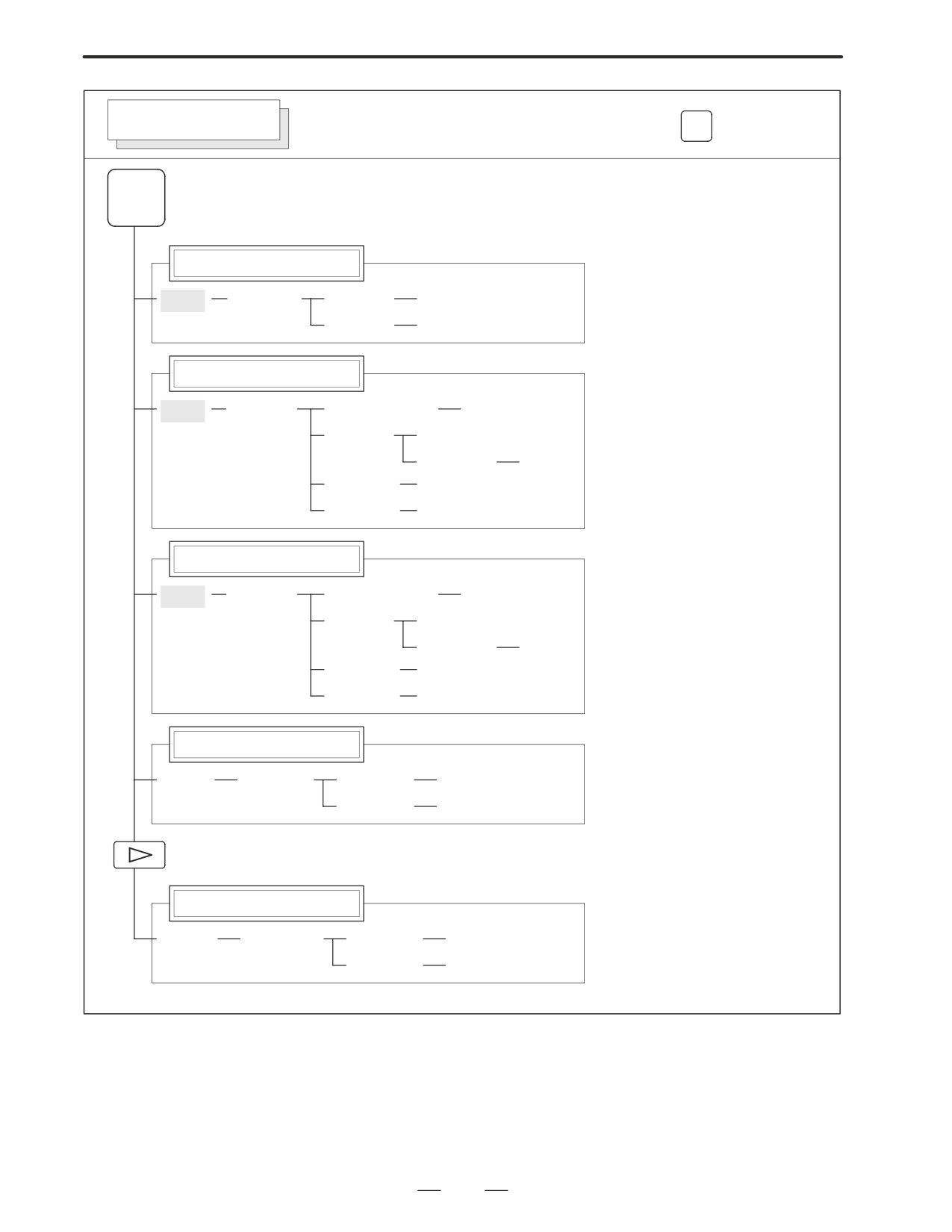
POSITION SCREEN
Soft key transition triggered by the function key
POS
POS
Absolute coordinate display
[ABS]
[(OPRT)]
[PTSPRE]
[EXEC]
[RUNPRE]
[EXEC]
Relative coordinate display
[REL]
[(OPRT)]
(Axis or numeral)
[PRESET]
[ORIGIN]
[ALLEXE]
[Axis name]
[EXEC]
[PTSPRE]
[EXEC]
[RUNPRE]
[EXEC]
Current position display
[ALL]
[(OPRT)]
(Axis or numeral)
[PRESET]
[ORIGIN]
[ALLEXE]
[Axis name]
[EXEC]
[PTSPRE]
[EXEC]
[RUNPRE]
[EXEC]
Handle interruption
[HNDL]
[(OPRT)]
[PTSPRE]
[EXEC]
[RUNPRE]
[EXEC]
Monitor screen
[MONI]
[(OPRT)]
[PTSPRE]
[EXEC]
[RUNPRE]
[EXEC]
3
1. DISPLAY AND OPERATION
B-63005EN/01
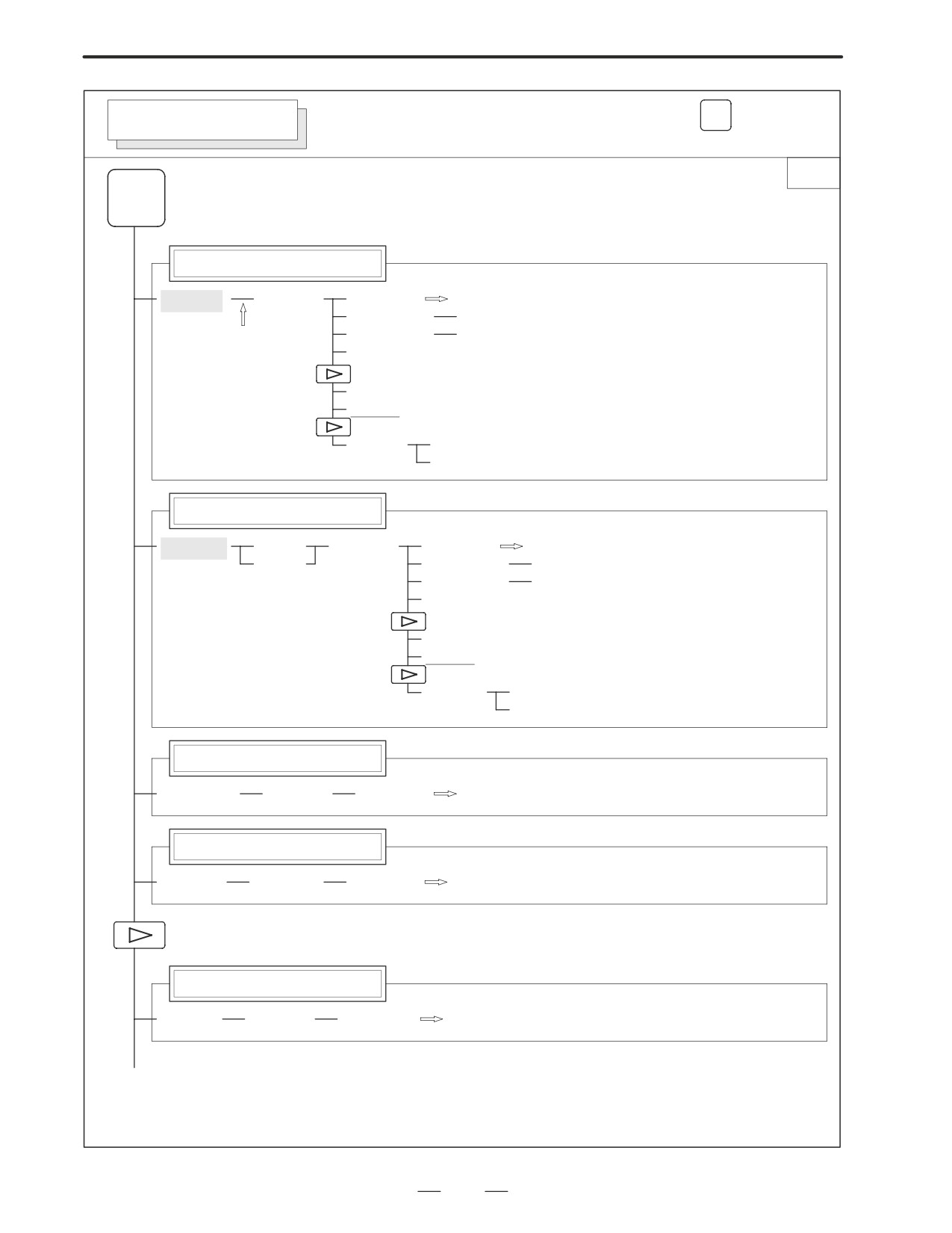
Soft key transition triggered by the function key
PROG
PROGRAM SCREEN
in the MEM mode
1/2
PROG
Program display screen
[PRGRM]
[(OPRT)]
[BG-EDT]
See “When the soft key [BG-EDT] is pressed”
[O number]
[O SRH]
[N number]
[N SRH]
(1)
[REWIND]
[P TYPE]
[Q TYPE]
[F SRH]
[CAN]
[EXEC]
Program check display screen
[CHECK]
[ABS]
[(OPRT)]
[BG-EDT]
See “When the soft key [BG-EDT] is pressed”
[REL]
[O number]
[O SRH]
[N number]
[N SRH]
[REWIND]
[P TYPE]
[Q TYPE]
[F SRH]
[CAN]
[EXEC]
Current block display screen
[CURRNT]
[(OPRT)]
[BG-EDT]
See “When the soft key [BG-EDT] is pressed”
Next block display screen
[NEXT]
[(OPRT)]
[BG-EDT]
See “When the soft key [BG-EDT] is pressed”
Program restart display screen
[RSTR]
[(OPRT)]
[BG-EDT]
See “When the soft key [BG-EDT] is pressed”
(2)(Continued on the next page)
4
B-63005EN/01
1. DISPLAY AND OPERATION
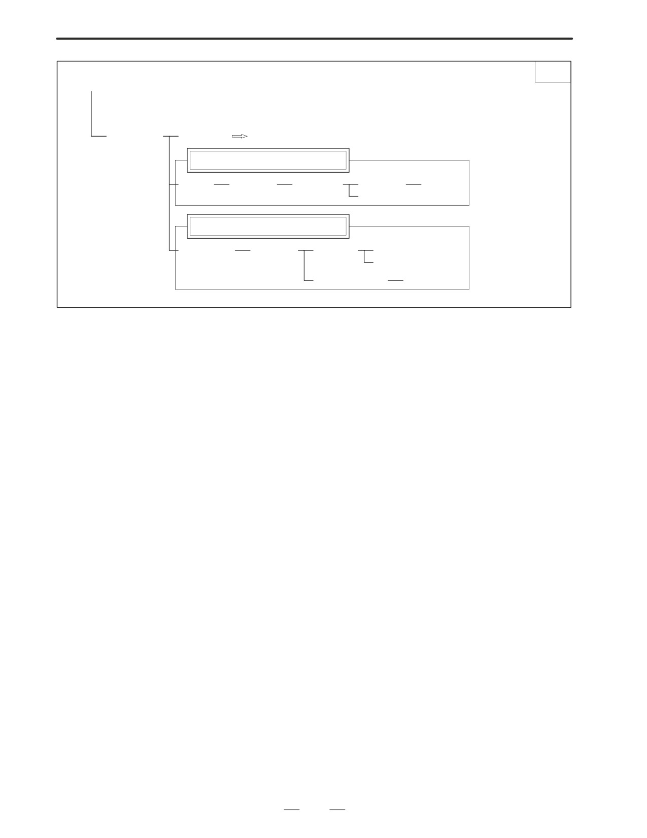
2/2
(2)
[FL.SDL]
[PRGRM]
Return to (1) (Program display)
File directory display screen
[DIR]
[(OPRT)]
[SELECT]
[File No. ]
[F SET]
[EXEC]
Schedule operation display screen
[SCHDUL]
[(OPRT)]
[CLEAR]
[CAN]
[EXEC]
(Schedule data)
[INPUT]
5
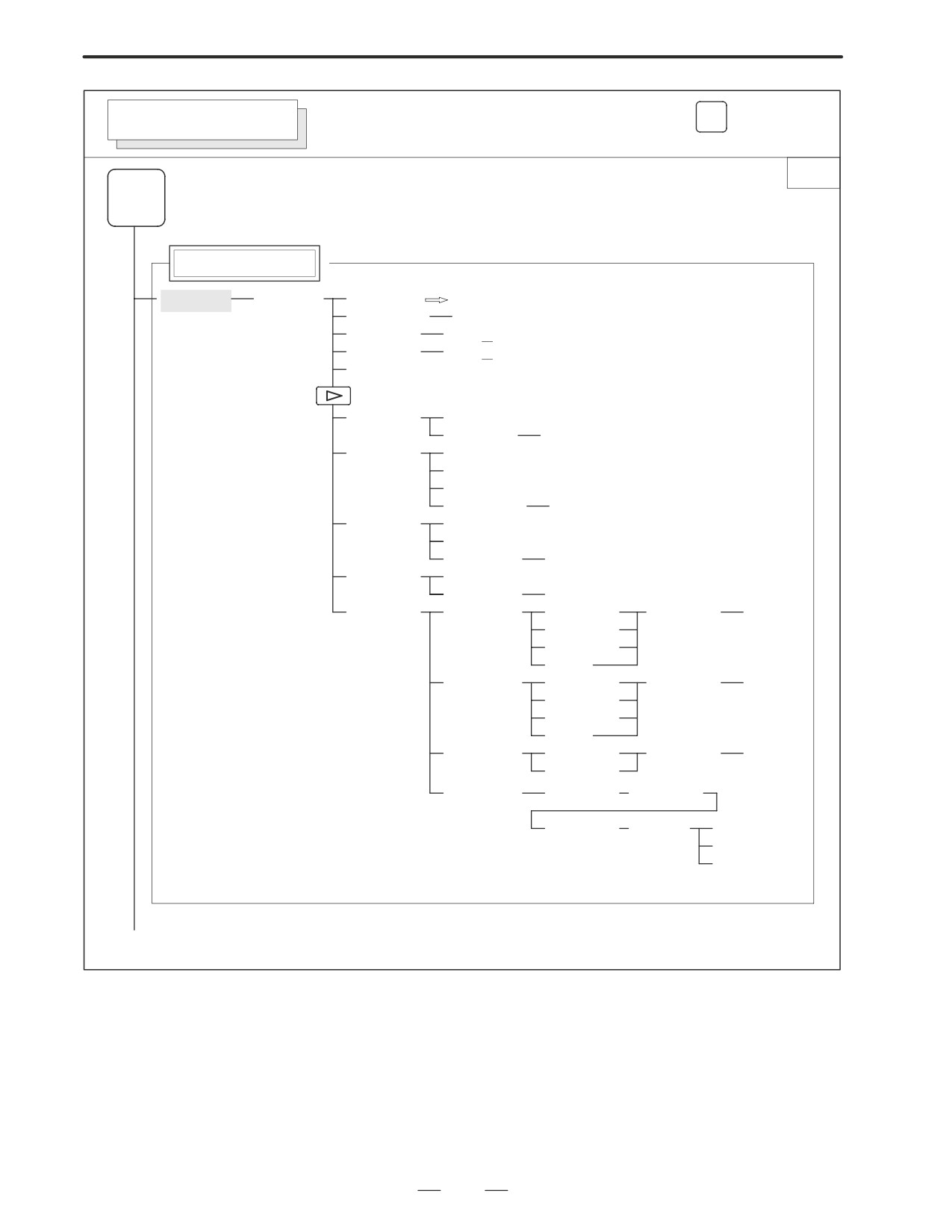
1. DISPLAY AND OPERATION
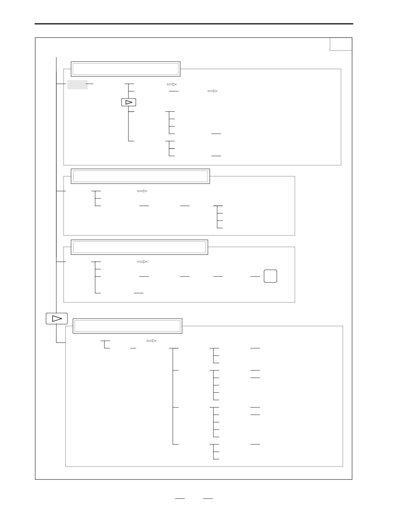
B-63005EN/01
Soft key transition triggered by the function key
PROG
PROGRAM SCREEN
in the EDIT mode
1/2
PROG
Program display
[PRGRM]
[(OPRT)]
[BG-EDT]
See “When the soft key [BG-EDT] is pressed”
(O number)
[O SRH]
(Address)
[SRH↓]
(Address)
[SRH↑]
[REWIND]
[F SRH]
[CAN]
(N number)
[EXEC]
[READ]
[CHAIN]
(The cursor moves to the end of a program.)
[STOP]
[CAN]
(O number)
[EXEC]
[PUNCH]
[STOP]
[CAN]
(O number)
[EXEC]
[DELETE]
[CAN]
(N number)
[EXEC]
[EX-EDT]
[COPY]
[CRSR∼]
(O number)
[EXEC]
[∼CRSR]
[∼BTTM]
[ALL]
[MOVE]
[CRSR∼]
(O number)
[EXEC]
[∼CRSR]
[∼BTTM]
[ALL]
[MERGE]
[∼CRSR]
(O number)
[EXEC]
[∼BTTM]
[CHANGE]
(Address)
[BEFORE]
(Address)
[AFTER]
[SKIP]
[1-EXEC]
[EXEC]
(1)(Continued on the next page)
6
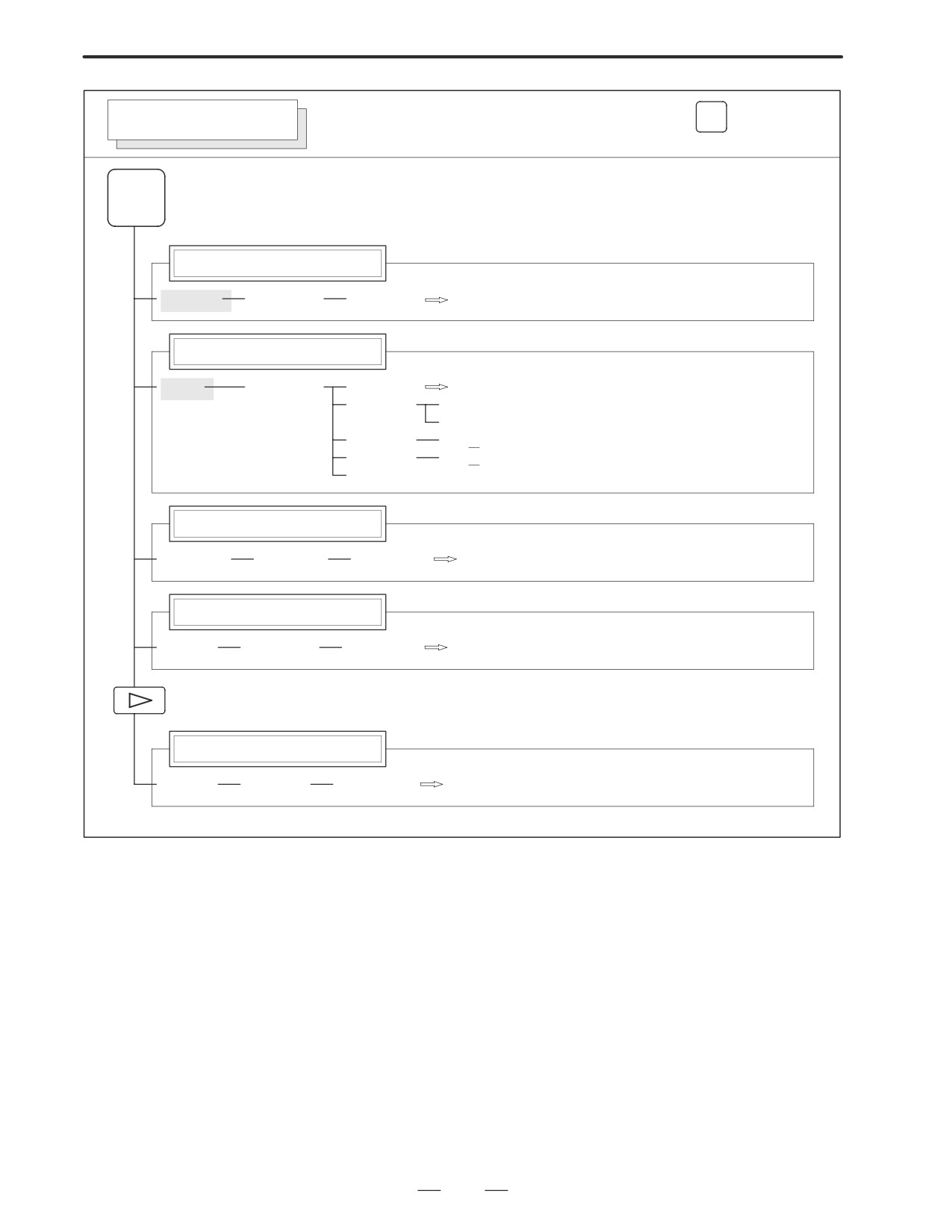
B-63005EN/01
1. DISPLAY AND OPERATION
2/2
(1)
Program directory display
[LIB]
[(OPRT)]
[BG-EDT]
See “When the soft key [BG-EDT] is pressed”
(O number)
[O SRH]
Return to the program
[READ]
[CHAIN]
[STOP]
[CAN]
(O number)
[EXEC]
[PUNCH]
[STOP]
[CAN]
(O number)
[EXEC]
Graphic Conversational Programming (T series)
[C.A.P.]
[PRGRM]
Return to the program
[G.MENU]
(G number)
[BLOCK]
(Data)
[LINE]
When a G number is omitted,
[CHAMF]
the standard screen appears.
[CNR.R]
[INPUT]
Graphic Conversational Programming (M series)
[C.A.P.]
[PRGRM]
Return to the program
[G.MENU]
(G number)
[BLOCK]
(Data)
[INPUT]
INSERT
When a G number is omitted, the standard screen appears.
[(OPRT)]
[INPUT]
Floppy directory display
[FLOPPY]
[PRGRM]
Return to the program
[DIR]
[(OPRT)]
[F SRH]
(Numeral)
[F SET]
[CAN]
[EXEC]
[READ]
(Numeral)
[F SET]
(Numeral)
[O SET]
[STOP]
[CAN]
[EXEC]
[PUNCH]
(Numeral)
[F SET]
(Numeral)
[O SET]
[STOP]
[CAN]
[EXEC]
[DELETE]
(Numeral)
[F SET]
[CAN]
[EXEC]
7
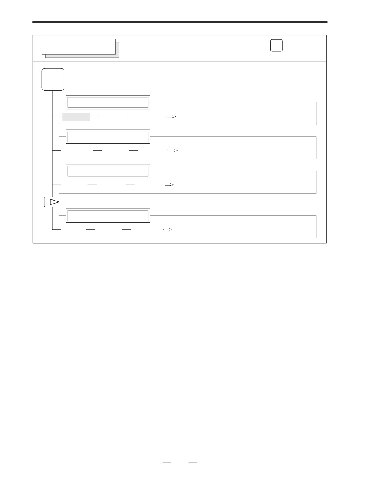
1. DISPLAY AND OPERATION
B-63005EN/01
Soft key transition triggered by the function key
PROG
PROGRAM SCREEN
in the MDI mode
PROG
Program display
[PRGRM]
[(OPRT)]
[BG-EDT]
See “When the soft key [BG-EDT] is pressed”
Program input screen
[MDI]
[(OPRT)]
[BG-EDT]
See “When the soft key [BG-EDT] is pressed”
[START]
[CAN]
[EXEC]
(Address)
[SRH↓]
(Address)
[SRH↑]
[REWIND]
Current block display screen
[CURRNT]
[(OPRT)]
[BG-EDT]
See When the soft key [BG-EDT] is pressed"
Next block display screen
[NEXT]
[(OPRT)]
[BG-EDT]
See “When the soft key [BG-EDT] is pressed”
Program restart display screen
[RSTR]
[(OPRT)]
[BG-EDT]
See “When the soft key [BG-EDT] is pressed”
8
B-63005EN/01
1. DISPLAY AND OPERATION
Soft key transition triggered by the function key
PROG
PROGRAM SCREEN
in the HNDL, JOG, or REF mode
PROG
Program display
[PRGRM]
[(OPRT)]
[BG-EDT]
See “When the soft key [BG-EDT] is pressed”
Current block display screen
[CURRNT]
[(OPRT)]
[BG-EDT]
See “When the soft key [BG-EDT] is pressed”
Next block display screen
[NEXT]
[(OPRT)]
[BG-EDT]
See “When the soft key [BG-EDT] is pressed”
Program restart display screen
[RSTR]
[(OPRT)]
[BG-EDT]
See “When the soft key [BG-EDT] is pressed”
9
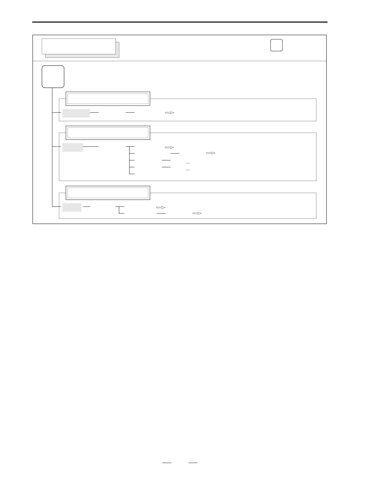
1. DISPLAY AND OPERATION
B-63005EN/01
Soft key transition triggered by the function key
PROG
PROGRAM SCREEN
in the TJOG or THDL mode
PROG
Program display
[PRGRM]
[(OPRT)]
[BG-EDT]
See “When the soft key [BG-EDT] is pressed”
Program input screen
[MDI]
[(OPRT)]
[BG-EDT]
See “When the soft key [BG-EDT] is pressed”
(O number)
[O SRH]
Return to the program
(Address)
[SRH↓]
(Address)
[SRH↑]
[REWIND]
Program directory display
[LIB]
[(OPRT)]
[BG-EDT]
See “When the soft key [BG-EDT] is pressed”
(O number)
[O SRH]
Return to the program
10
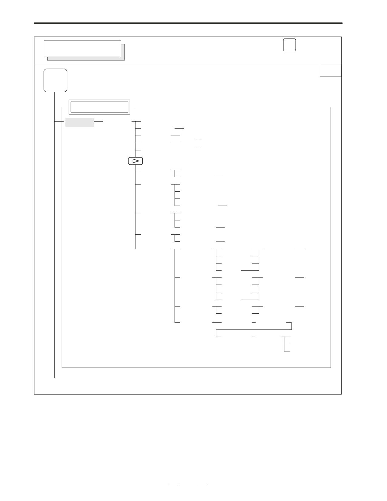
B-63005EN/01
1. DISPLAY AND OPERATION
PROG
Soft key transition triggered by the function key
PROGRAM SCREEN
(When the soft key [BG-EDT] is pressed in all modes)
1/2
PROG
Program display
[PRGRM]
[(OPRT)]
[BG-END]
(O number)
[O SRH]
(Address)
[SRH↓]
(Address)
[SRH↑]
[REWIND]
[F SRH]
[CAN]
(N number)
[EXEC]
[READ]
[CHAIN]
(The cursor moves to the end of a program.)
[STOP]
[CAN]
(O number)
[EXEC]
[PUNCH]
[STOP]
[CAN]
(O number)
[EXEC]
[DELETE]
[CAN]
(N number)
[EXEC]
[EX-EDT]
[COPY]
[CRSR∼]
(O number)
[EXEC]
[∼CRSR]
[∼BTTM]
[ALL]
[MOVE]
[CRSR∼]
(O number)
[EXEC]
[∼CRSR]
[∼BTTM]
[ALL]
[MERGE]
[∼CRSR]
(O number)
[EXEC]
[∼BTTM]
[CHANGE]
(Address)
[BEFORE]
(Address)
[AFTER]
[SKIP]
[1-EXEC]
[EXEC]
(1)(Continued on the next page)
11
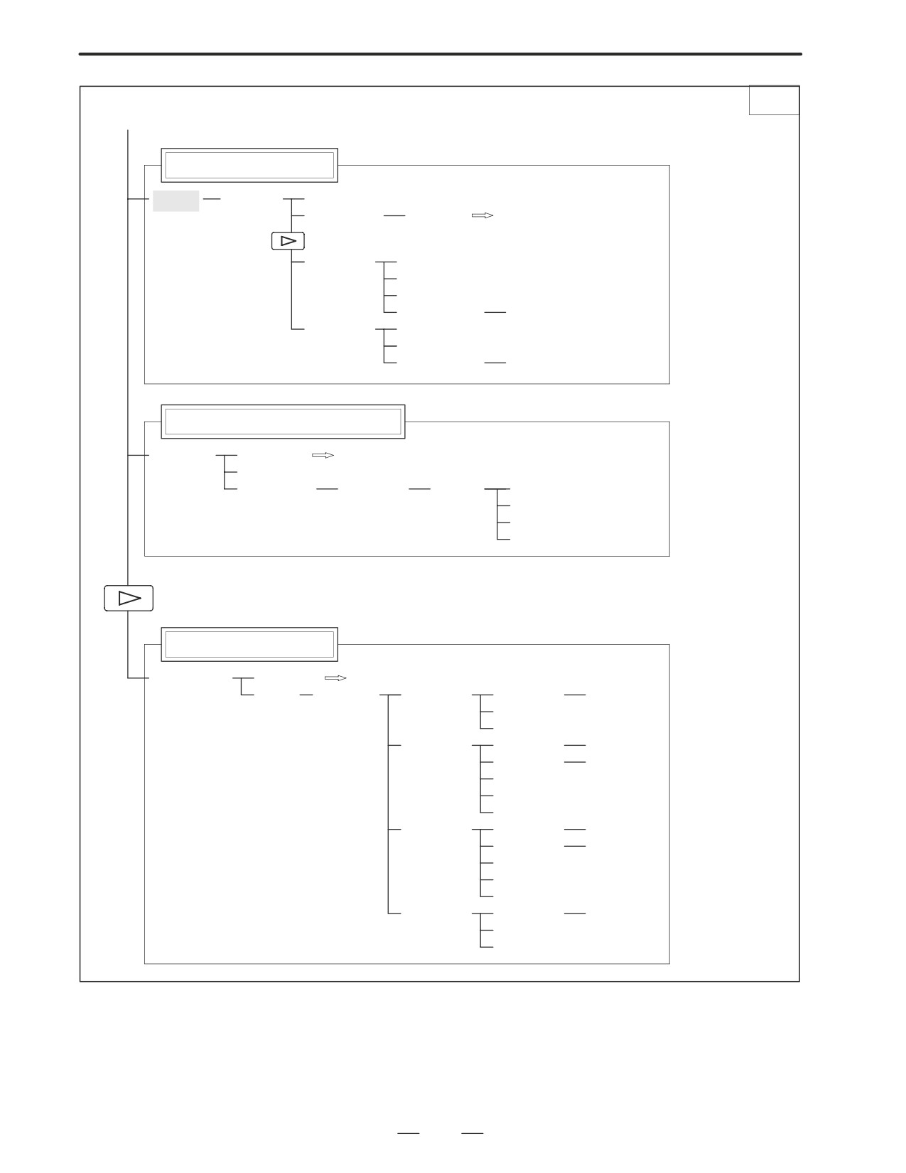
1. DISPLAY AND OPERATION
B-63005EN/01
2/2
(1)
Program directory display
[LIB]
[(OPRT)]
[BG-EDT]
(O number)
[O SRH]
Return to the program
[READ]
[CHAIN]
[STOP]
[CAN]
(O number)
[EXEC]
[PUNCH]
[STOP]
[CAN]
(O number)
[EXEC]
Graphic Conversational Programming
[C.A.P.]
[PRGRM]
Return to the program
[G.MENU]
(G number)
[BLOCK]
(Data)
[LINE]
[CHAMF]
When a G number is omitted, the standard
screen appears.
[CNR.R]
[INPUT]
Floppy directory display
[FLOPPY]
[PRGRM]
Return to the program
[DIR]
[(OPRT)]
[F SRH]
(Numeral)
[F SET]
[CAN]
[EXEC]
[READ]
(Numeral)
[F SET]
(Numeral)
[O SET]
[STOP]
[CAN]
[EXEC]
[PUNCH]
(Numeral)
[F SET]
(Numeral)
[O SET]
[STOP]
[CAN]
[EXEC]
[DELETE]
(Numeral)
[F SET]
[CAN]
[EXEC]
12
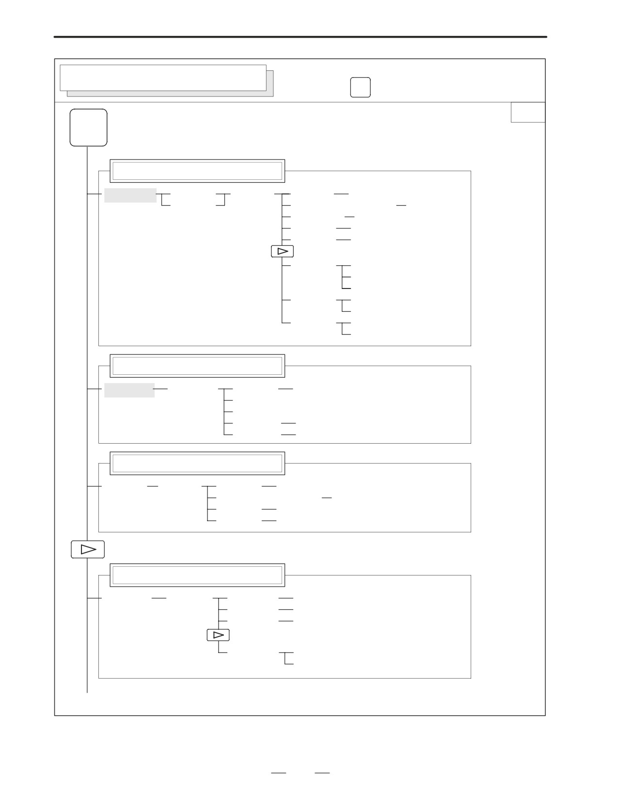
B-63005EN/01
1. DISPLAY AND OPERATION
Soft key transition triggered by the
OFFSET/SETTING SCREEN (T series)
function key
OFFSET
SETTING
1/2
OFFSET
SETTING
Tool offset screen
[OFFSET]
[WEAR]
[(OPRT)]
(Number)
[NO SRH]
[GEOM]
(Axis name and numeral)
[MEASUR]
(Axis name)
[INP.C.]
(Numeral)
[+INPUT]
(Numeral)
[INPUT]
[CLEAR]
[ALL]
[WEAR]
[GEOM]
[READ]
[CAN]
[EXEC]
[PUNCH]
[CAN]
[EXEC]
Setting screen
[SETING]
[(OPRT)]
(Number)
[NO SRH]
[ON:1]
[OFF:0]
(Numeral)
[+INPUT]
(Numeral)
[INPUT]
Work coordinate system setting screen
[WORK]
[(OPRT)]
(Number)
[NO SRH]
(Axis name and numeral)
[MEASUR]
(Numeral)
[+INPUT]
(Numeral)
[INPUT]
Macro variables display screen
[MACRO]
[(OPRT)]
(Number)
[NO SRH]
(Axis name)
[INP.C.]
(Numeral)
[INPUT]
[PUNCH]
[CAN]
[EXEC]
(1)(Continued on the next page)
13
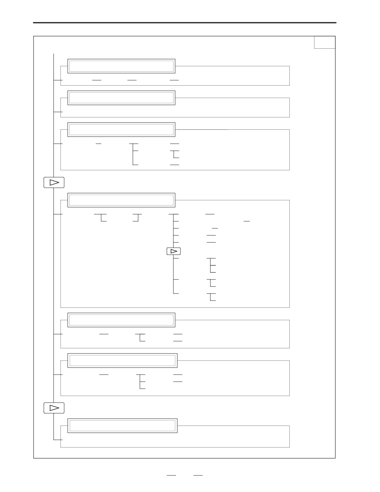
1. DISPLAY AND OPERATION
B-63005EN/01
2/2
(1)
Menu programming screen
[MENU]
[(OPRT)]
(Number)
[SELECT]
Software operator’s panel screen
[OPR]
Tool life management setting screen
[TOOLLF]
[(OPRT)]
(Number)
[NO SRH]
[CLEAR]
[CAN]
[EXEC]
(Numeral)
[INPUT]
Y axis tool offset screen
[OFST
.2]
[WEAR]
[(OPRT)]
(Number)
[NO SRH]
[GEOM]
(Axis name and numeral)
[MEASUR]
(Axis name)
[INP.C.]
(Numeral)
[+INPUT]
(Numeral)
[INPUT]
[CLEAR]
[ALL]
[WEAR]
[GEOM]
[READ]
[CAN]
[EXEC]
[PUNCH]
[CAN]
[EXEC]
Workpiece shift screen
[WK.SHFT]
[(OPRT)]
(Numeral)
[+INPUT]
(Numeral)
[INPUT]
Chuck/tailstock barrier setting screen
[BARRIER]
[(OPRT)]
(Numeral)
[INPUT]
(Numeral)
[+INPUT]
[SET]
B axis tool offset screen
[OFST.B]
14
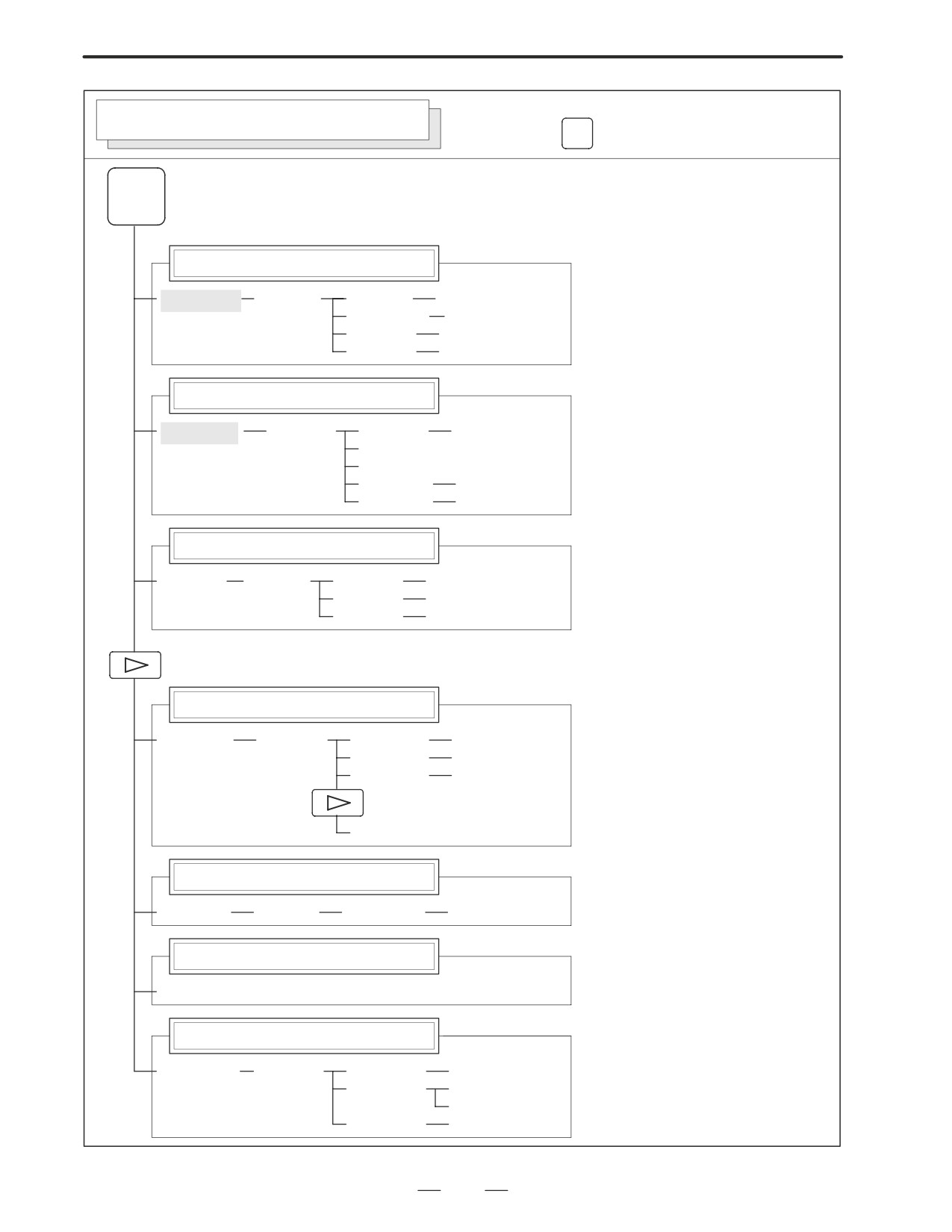
B-63005EN/01
1. DISPLAY AND OPERATION
Soft key transition triggered by the
OFFSET/SETTING SCREEN (M series)
function key
OFFSET
SETTING
OFFSET
SETTING
Tool offset screen
[OFFSET]
[(OPRT)]
(Number)
[NO SRH]
(Axis name)
[INP.C.]
(Numeral)
[+INPUT]
(Numeral)
[INPUT]
Setting screen
[SETING]
[(OPRT)]
(Number)
[NO SRH]
[ON:1]
[OFF:0]
(Numeral)
[+INPUT]
(Numeral)
[INPUT]
Work coordinate system setting screen
[WORK]
[(OPRT)]
(Number)
[NO SRH]
(Numeral)
[+INPUT]
(Numeral)
[INPUT]
Macro variables display screen
[MACRO]
[(OPRT)]
(Number)
[NO SRH]
(Axis name)
[INP.C.]
(Numeral)
[INPUT]
[PUNCH]
Patten data input screen
[MENU]
[(OPRT)]
(Number)
[SELECT]
Software operator’s panel screen
[OPR]
Tool life management setting screen
[TOOLLF]
[(OPRT)]
(Number)
[NO SRH]
[CLEAR]
[CAN]
[EXEC]
(Numeral)
[INPUT]
15
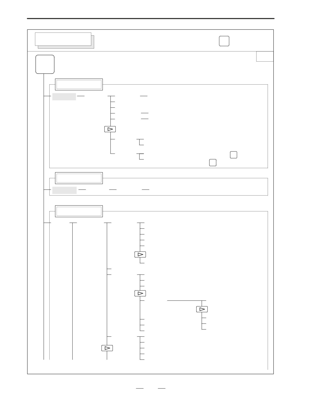
1. DISPLAY AND OPERATION
B-63005EN/01
SYSTEM SCREEN
Soft key transition triggered by the function key
SYSTEM
1/3
SYSTEM
Parameter screen
[PARAM]
[(OPRT)]
(Number)
[NO SRH]
[ON:1]
[OFF:0]
(Numeral)
[+INPUT]
(Numeral)
[INPUT]
[READ]
[CAN]
[EXEC]
[PUNCH]
[CAN]
N
To enter a file number: Press
, enter a file
[EXEC]
number, then press
INPUT
on the PRGRM screen
Diagnosis screen
[DGNOS]
[(OPRT)]
(Number)
[NO SRH]
PMC screen
[PMC]
[PMCLAD]
[SEARCH]
[TOP]
[BOTTOM]
[SRCH]
[W-SRCH]
[N-SRCH]
[F-SRCH]
[ADRESS]/[SYMBOL]
[TRIGER]
[TRGON]
[TRGOFF]
[START]
[DUMP]
[SEARCH]
[BYTE]
[DPARA]/[NDPARA]
[WORD]
[TRGSRC]
[D.WORD]
[INIT]
[WINDOW]
[DIVIDE]
[CANCEL]
[DELETE]
[SELECT]
[WIDTH]
(1)
(2)
(3)
(Continued on the next page)
16
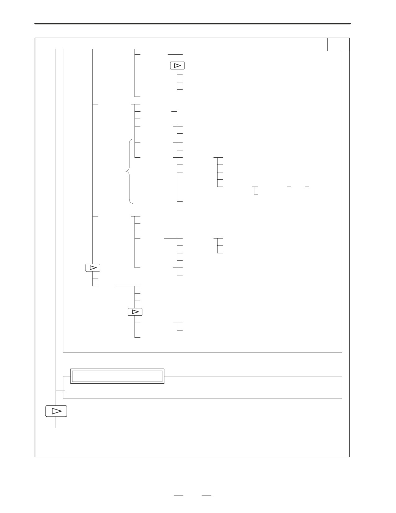
B-63005EN/01
1. DISPLAY AND OPERATION
(1)
(2)
(3)
2/3
[DUMP]
[SEARCH]
[BYTE]
[WORD]
[D.WORD]
[DRARA]/[NDPARA]
[PMCDGN]
[TITLE]
[STATUS]
[SEARCH]
[ALARM]
[TRACE]
[T.DISP]/[TRCPRM]
[EXEC]
[M.SRCH]
[SEARCH]
[INPUT]
[ANALYS]
[SCOPE]
[SGNPRM]
With
[DELETE]
[START]/[STOP]
PMC-RC
[INIT]
[T-SRCH]
only
[ADRESS]/[SYMBOL]
[EXCHG]
[SELECT]
[TO]
[EXEC]
[CANCEL]
[ADRESS]/[SYMBOL]
[PMCPRM]
[TIMER]
[COUNTR]
[KEEPRL]
[DATA]
[G.DATA]
[C.DATA]
[G.CONT]
[G-SRCH]
[NO.SRH]
[SEARCH]
[INIT]
[SETTING]
[YES]/[MANUAL]/[ROM]
[NO]/[AUTO]/[RAM]
[STOP]/[RUN]
[I/O]
[EXEC]
[CANCEL]
(No.)
[SPEED]
[INPUT]
[INIT]
[MDI]/[ROM]
System configuration screen
[SYSTEM]
(4)
(Continued on the next page)
17
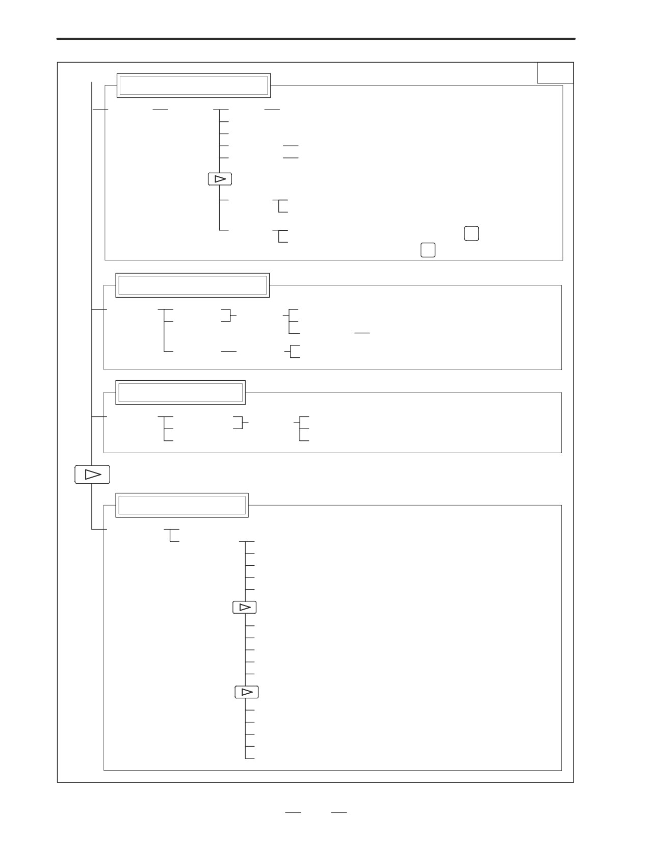
1. DISPLAY AND OPERATION
B-63005EN/01
(4)
3/3
Pitch error compensation screen
[PITCH]
[(OPRT)]
(No.)
[NO SRH]
[ON:1]
[OFF:0]
(Numeral)
[+INPUT]
(Numeral)
[INPUT]
[READ]
[CAN]
[EXEC]
[PUNCH]
[CAN]
N
, enter a file
[EXEC] To enter a file number: Press
INPUT
number, then press
on the PRGRM screen
Servo parameter screen
[SV.PRM]
[SV.SET]
[ON:1]
[(OPRT)]
[SV.TUN]
[OFF:0]
(Numeral)
[INPUT]
[TRACE]
[SV.TRC]
[(OPRT)]
[TRNSF]
Spindle parameter screen
[SP.PRM]
[SP.SET]
[ON:1]
[(OPRT)]
[SP.TUN]
[OFF:0]
[SP.MON]
[INPUT]
Waveform diagnosis screen
[W.DGNS]
[W.PRM]
[W.GRPH]
[STSRT]
[TIME→]
[←TIME]
[H-DOBL]
[H-HALF]
[STSRT]
[CH-1↑]
[CH-1↓]
[V-DOBL]
[V-HALF]
[STSRT]
[CH-2↑]
[CH-2↓]
[V-DOBL]
[V-HALF]
18
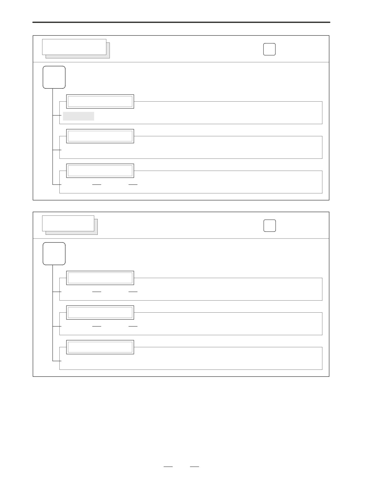
B-63005EN/01
1. DISPLAY AND OPERATION
MESSAGE SCREEN
Soft key transition triggered by the function key
MESSAGE
MESSAGE
Alarm display screen
[ALARM]
Message display screen
[MSG]
Alarm history screen
[HISTRY]
[(OPRT)]
[CLEAR]
HELP SCREEN
Soft key transition triggered by the function key
HELP
HELP
Alarm detail screen
[ALARM]
[(OPRT)]
[SELECT]
Operation method screen
[OPERAT]
[(OPRT)]
[SELECT]
Parameter table screen
[PARAM]
19