FANUC Series 90-30 PLC. Installation and Hardware Manual (GFK-0356P) - page 15
K
Key in the new PLC ID. For newer CPUs, it may be from one to seven
alpha-numeric characters long. For older CPUs, it is limited to a maximum of six
characters. For example, it could be PLC1, APM001, A1, B00001, etc.
Press the Enter key. The new SNP ID will be written to the PLC and the CURRENT
PLC ID field on your screen will update to show this new SNP ID.
Repeat the above steps for each PLC that is on the multidrop system. If assigning
an SNP ID to a module, you must use the appropriate software. See the user ’s
manual for the module for instructions.
Connecting your Logicmaster Programmer to a PLC on a Multidrop System
Connect your programmer to the programmer connection for the multidrop system.
From the Logicmaster Main Menu, select F2, “Logicmaster 90 Configuration
Package.”
Select F7, “Programmer Mode and Setup.”
Select F3, “Select PLC Connections.”
In the SELECTED SNP ID field, enter the SNP ID of the PLC or device you wish to
communicate with.
In the PORT CONNECTION field, select MULTIDROP.
Press F6, “setup,” to connect to the selected PLC. You should connect to the selected
PLC within a few seconds. If you cannot connect, see the next section.
SNP Multidrop Troubleshooting
If you are having trouble connecting to a PLC or module over the multidrop system,
check the following:
Is there a problem with all PLCs or only one? Try connecting to other PLCs over
the multidrop system. If you cannot connect to any, check for a common problem
such as a defective cable. If you can connect to all but one PLC, use the direct
connection method described in the next paragraph. Also, if you only have a
problem with the last PLC on the multidrop link, the last section of cable may have a
problem. Or, perhaps you can connect to all PLCs up to a certain point, but none
beyond that point. This would also strongly suggest that there is a problem in a
section of cable.
SNP ID may be incorrect. You may not be able to connect because you are
specifying the wrong SNP ID. If you are not sure of a PLC’s correct SNP ID and
would like to check it, you can connect your programmer directly to the PLC’s
programmer port and read its SNP ID from the software’s ASSIGN PLC ID screen,
(as described in “Assigning an SNP ID to a PLC with Logicmaster,” above). Make
sure you change the programming software’s connection method to Direct for this
test. When set for Direct connection, the software will communicate with a directly
connected PLC without regard to its SNP ID.
Communications settings may not match. If the PLC’s serial port communication
settings and the programming software’s communication settings do not match,
they will not be able to communicate. These settings include such things as BAUD
Rate, Parity, Stop Bits, etc. If you suspect this to be the problem, try connecting
directly to the PLC as described above in “SNP ID may be incorrect.” If you cannot
K-6
Series 90-30 PLC Installation and Hardware Manual - October 1999
GFK-0356P
K
connect directly, there may be a communication settings mismatch. If so, try setting
the programming software to its default communication settings.
Multidrop may not be selected as the connection method. The default connection
method in the programming software is Direct, which requires that you be
connected directly to a PLC or module’s programmer port. If this default setting is
not changed to Multidrop, you will not be able to connect to a selected SNP ID over
a multidrop system.
You may have a hardware problem. Inspect the multidrop cable; it may be wired
incorrectly, damaged, or disconnected. A wire may be loose on one of the
connectors. Also check the status of the PLC you are trying to connect to. It may not
be powered up; it may be stopped; or it may have some other problem. Eliminate
the PLC itself as a possible problem by connecting your programmer directly to the
PLC’s programmer port. You should be able to communicate with a PLC using this
direct connection even if the programming software is configured for Multidrop, as
long as the SNP IDs match.
GFK-0356P
Appendix K SNP Multidrop
K-7
Appendix
L Ethernet Transceivers
section level 1
figure_ap level 1
L
table_ap level 1
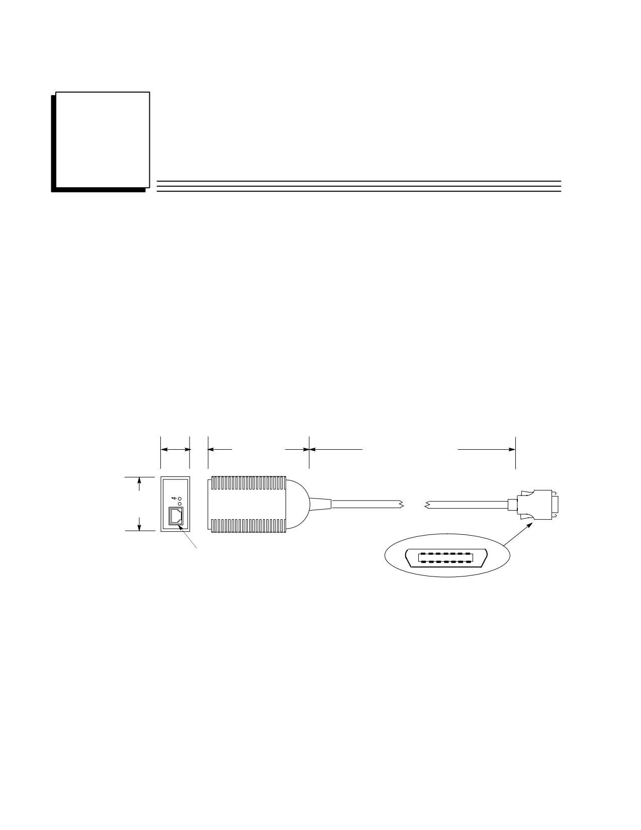
IC649AEA102 Ethernet 10BASE-T Transceiver
Compliant with the IEEE 802.3 Ethernet specification for 10BASE-T.
Connector on transceiver body is standard RJ-45 type for connection to unshielded
twisted pair (UTP) Ethernet cable. .
This unit has an attached 40” (1 meter) cable with standard 14-pin AAUI connector
for connecting to a Series 90-30 Ethernet module (IC693CMM321) or CPU with
Ethernet interface (IC693CPU364).
SQE option is enabled.
Power and Link Integrity LED indicator lights.
1”
3.5” (89 mm)
40 inches (1 meter)
(25mm)
1.8”
LI
(46mm)
7 6 5 4 3 2
1
14-Pin AAUI
8-Pin RJ-45
Connector
Connector
8
9 10111213 14
Figure L-1. IC649AEA102 Ethernet 10BASE-T Transceiver
Power Requirement
This unit draws 60 mA @ 5Vdc from the Ethernet interface via the AAUI connector.
LED Indicator Lights
These are located on the end of the unit next to the RJ-45 connector. The one labeled LI
stays on as long as Link Integrity is maintained. The one marked with a “jagged arrow”
symbol indicates the presence of 5Vdc power to the unit.
GFK-0356P
L-1
L
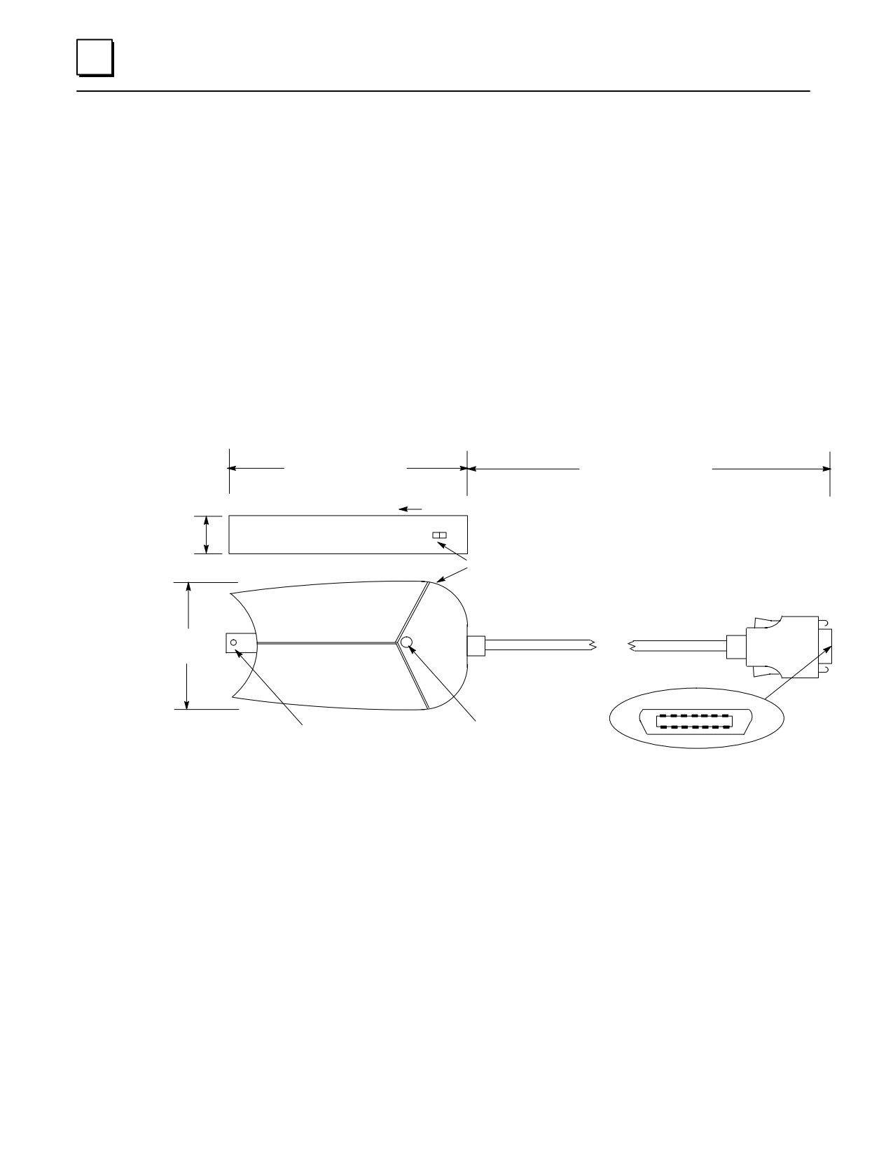
IC649AEA103 Ethernet 10BASE2 Transceiver
Note: This transceiver replaces obsolete catalog number IC649AEA101
Compliant with the IEEE 802.3 Ethernet specification for 10BASE2.
A standard BNC connector is mounted on the body of the transceiver for connection
to thin coaxial Ethernet cable.
This unit has an attached 10” (254 mm) cable with standard 14-pin AAUI connector
for connecting to a Series 90-30 Ethernet module (IC693CMM321) or CPU with
Ethernet interface (IC693CPU364).
SQE slide switch is set to enabled position at the factory. It must be in this position
for proper operation with GE Fanuc Ethernet products IC693CMM321 and
IC693CPU364 (see figure below).
Power LED indicator light.
3.2 inches (81 mm)
10 inches (254mm)
0.9”
(23 mm)
Slide Switch in this Direction to Enable SQE.
SQE Slide Switch (recessed in housing)
14-Pin AAUI
Connector
2 inches
(51 mm)
7 6 5 4 3 2
1
Green LED
BNC Connector
8
9 10111213 14
Power Indicator
Figure L-2. IC649AEA103 Ethernet 10BASE2 Transceiver
Power Requirement
This unit draws 400 mA @ 5Vdc from the Ethernet Interface via the AAUI connector.
LED Indicator Light
Located on the side of the unit as shown in the figure. This green LED turns on to
indicate the presence of 5Vdc power to the unit.
L-2
Series 90-30 PLC Installation and Hardware Manual - October 1999
GFK-0356P
Appendix
Tables and Formulas
M
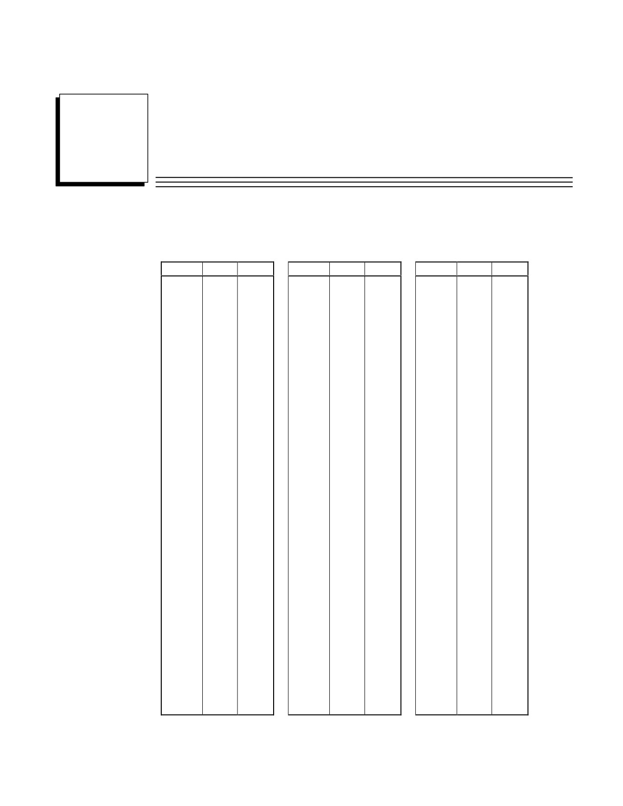
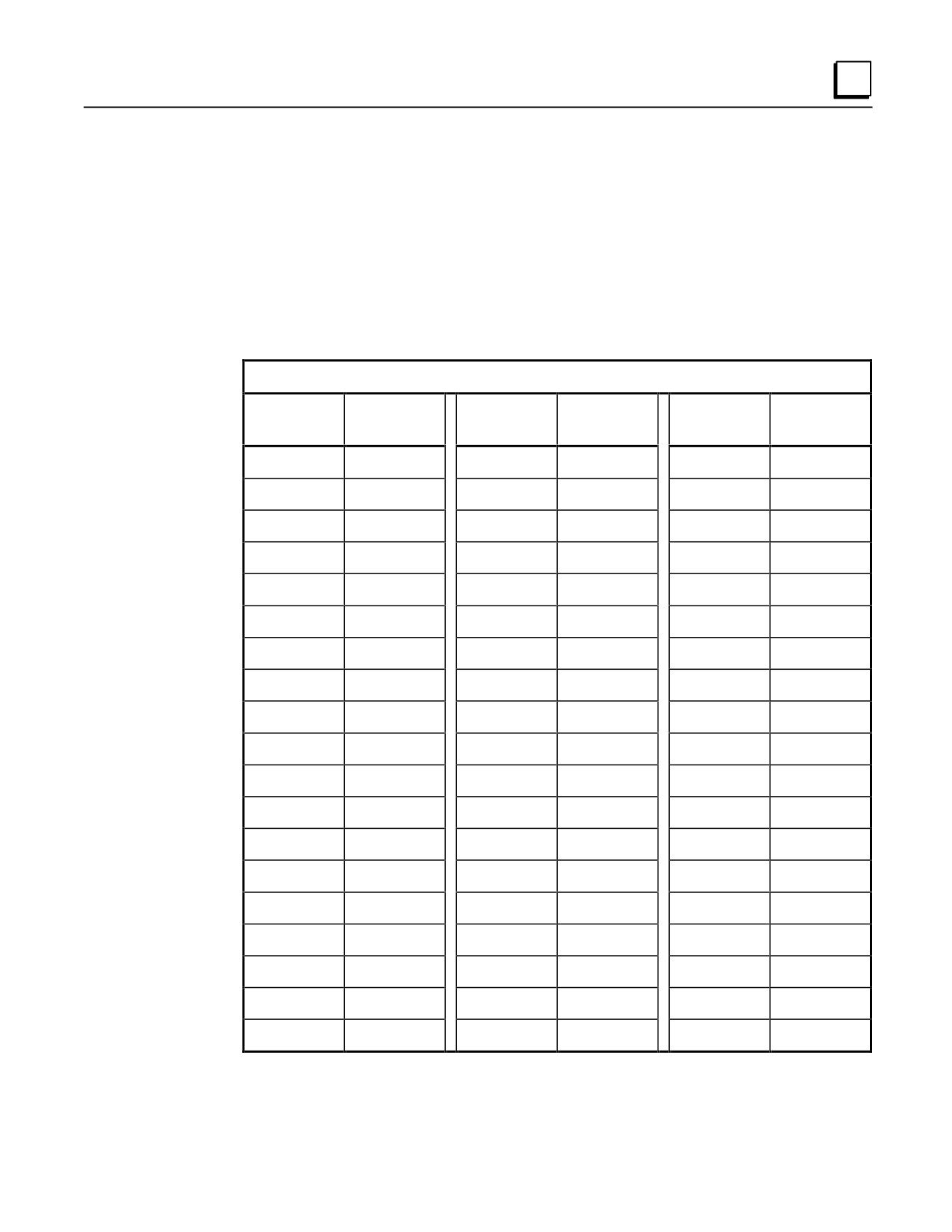
Table M-1. Standard ASCII (American Standard Code for Information Interchange) Codes
Char.
Dec.
Hex.
Char.
Dec.
Hex.
Char.
Dec.
Hex.
NUL
0
00
+
43
2B
V
86
56
SOH
1
01
,
44
2C
W
87
57
STX
2
02
-
45
2D
X
88
58
ETX
3
03
46
2E
Y
89
59
EOT
4
04
/
47
2F
Z
90
5A
ENQ
5
05
0
48
30
[
91
5B
ACK
6
06
1
49
31
\
92
5C
BEL
7
07
2
50
32
]
93
5D
BS
8
08
3
51
33
^
94
5E
HT
9
09
4
52
34
_
95
5F
LF
10
0A
5
53
35
`
96
60
VT
11
0B
6
54
36
a
97
61
FF
12
0C
7
55
37
b
98
62
CR
13
0D
8
56
38
c
99
63
SO
14
0E
9
57
39
d
100
64
SI
15
0F
:
58
3A
e
101
65
DLE
16
10
;
59
3B
f
012
66
DC1
17
11
<
60
3C
g
103
67
DC2
18
12
=
61
3D
h
104
68
DC3
19
13
>
62
3E
i
105
69
DC4
20
14
?
63
3F
j
106
6A
NAK
21
15
@
64
40
k
107
6B
SYN
22
16
A
65
41
l
108
6C
ETB
23
17
B
66
42
m
109
6D
CAN
24
18
C
67
43
n
110
6E
EM
25
19
D
68
44
o
111
6F
SUB
26
1A
E
69
45
p
112
70
ESC
27
1B
F
70
46
q
113
71
FS
28
1C
G
71
47
r
114
72
GS
29
1D
H
72
48
s
115
73
RS
30
1E
I
73
49
t
116
74
US
31
1F
J
74
4A
u
117
75
SP
32
20
K
75
4B
v
118
76
!
33
21
L
76
4C
w
119
77
”
34
22
M
77
4D
x
120
78
#
35
23
N
78
4E
y
121
79
$
36
24
O
79
4F
z
122
7A
%
37
25
P
80
50
{
123
7B
&
38
26
Q
81
51
|
124
7C
¢
39
27
R
82
52
}
125
7D
(
40
28
S
83
53
~
126
7E
)
41
29
T
84
54
“
127
7F
*
42
2A
U
85
55
GFK-0356P
M-1
M
AWG to Metric Wire Size Conversion
Since there is not an exact correspondence between American AWG wire sizes and metric sizes,
the metric values in the following table are close approximations. If you need greater precision,
contact your wire supplier.
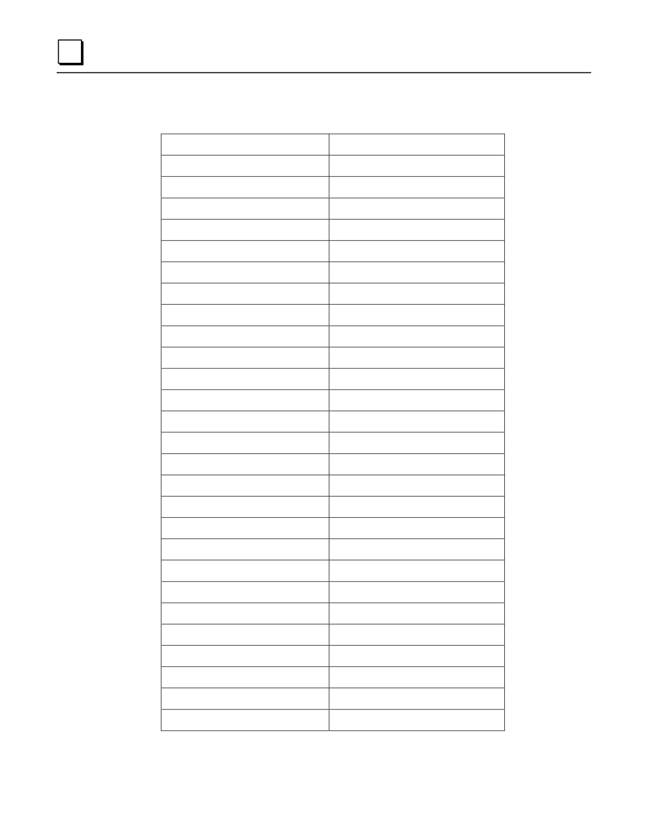
Table M-2. AWG to Metric Wire Size Conversion
AWG to Metric Wire Size Conversion
AWG Size
Metric Cross Section in
square millimeters (mm2 )
1
42.4
2
33.6
4
21.2
6
13.2
8
8.37
10
5.26
12
3.31
14
2.08
16
1.31
18
0.82
20
0.52
22
0.32
24
0.21
26
0.13
28
0.081
30
0.051
M-2
Series 90-30 PLC Installation and Hardware Manual - October 1999
GFK-0356P
M
Temperature Conversion
Formulas
°C = 5/9(°F - 32)
°F = (9/5 x °C) + 32
Table M-3. Celsius to Fahrenheit Conversion
Celsius to Fahrenheit Conversion (to nearest degree)
Degrees
Degrees
Degrees
Degrees
Degrees
Degrees
Celsius
Fahrenheit
Celsius
Fahrenheit
Celsius
Fahrenheit
-50
-58
50
122
145
293
-45
-49
55
131
150
302
-40
-40
60
140
155
311
-30
-22
65
149
160
320
-25
-13
70
158
165
329
-20
-4
75
167
170
338
-15
5
80
176
175
347
-10
14
85
185
180
356
-5
23
90
194
185
365
0
32
95
203
190
374
5
41
100
212
195
383
10
50
105
221
200
392
15
59
110
230
205
401
20
68
115
239
210
410
25
77
120
248
215
419
30
86
125
257
220
428
35
95
130
266
225
437
40
104
135
275
230
446
45
113
140
284
235
455
GFK-0356P
Appendix M Tables and Formulas
M-3
M
Conversion Information
Table M-4. General Conversions
1 ounce (weight) =
28.35 grams
1 pound (weight) =
453.6 grams
1 pound (weight) =
16 ounces
1 pound (force) =
4.448 newtons
1 short ton (weight)=
907.2 kilograms
1 short ton (weight)=
2,000 pounds
1 horsepower (power)=
550 foot-pounds per second
1 horsepower (power) =
746 watts of electrical power
1 kilowatt (power) =
1.341 horsepower
1 kilowatt-hour (energy or work) =
3,412.142 Btu
1 kilowatt-hour (energy or work) =
1,000 watts/hr.
1 watt (power) =
3.412 Btu/hr.
1 watt (power) =
1 joule/sec.
1 joule/sec. (power) =
1 watt
1 joule (energy)=
1 newton-meter
1 Btu =
0.293 watt
1 Btu =
778.2 foot-pounds
1 Btu =
252 gram-calories
1 Btu (energy)=
1055 joules
1 newton-meter (torque or work) =
0.7376 pound-feet
1 newton-meter (torque or work) =
8.851 pound-inches
1 pound-foot (torque or work) =
1.3558 newton-meters
1 pound-inch (torque or work) =
0.113 newton-meters
1 ounce-inch (torque or work) =
72 gram-centimeters
1 degree (angular) =
0.0175 radians
1 minute (angular) =
0.01667 degrees
1 radian (angular) =
57.3 degrees
1 quadrant (angular) =
90 degrees
M-4
Series 90-30 PLC Installation and Hardware Manual - October 1999
GFK-0356P
M
English and Metric Equivalents
This section is based upon information published on the World Wide Web by the U.S.
government’s National Institute of Standards and Technology (NIST). For further information,
visit their web site at www.nist.gov.
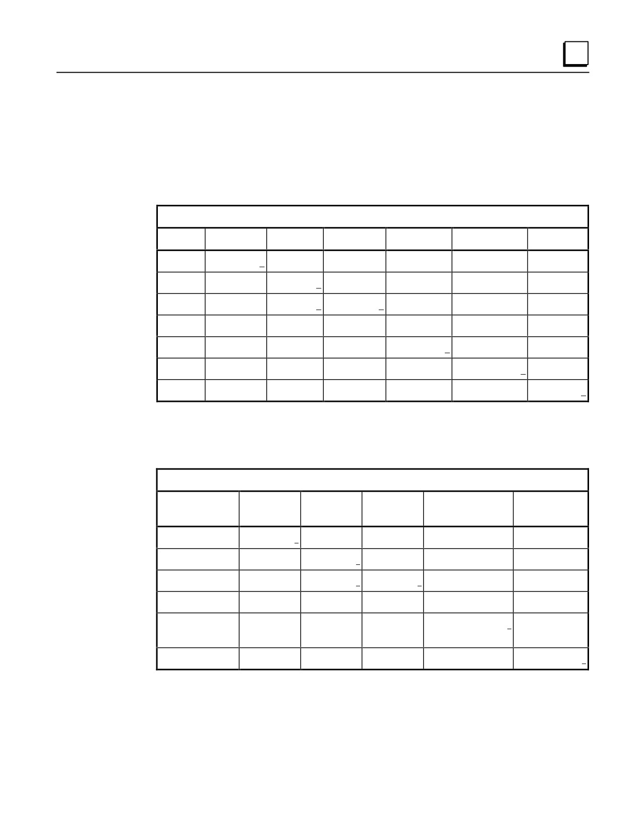
Table M-5. Length Equivalents
Units of Length (Underlined Figures are Exact)
Units
Inches
Feet
Yards
Millimeters
Centimeters
Meters
1 inch =
1
0.083 333
0.027 777
25.4
2.54
0.025 4
1 foot =
12
1
0.333 333
304.8
30.48
0.304 8
1 yard =
36
3
1
914.4
91.44
0.914 4
1 mile =
63,360
5,280
1,760
1,609,344
160,934.4
1,609.344
1 mm =
0.0393 700
0.003 280 8
0.001 093 6
1
.1
.001
1 cm =
0.393 700 8
0.032 808
0.010 936
10
1
0.01
1 meter =
39.370 08
3.280 840
1.093 613
1000
100
1
Table M-6. Area Equivalents
Units of Area (Underlined Figures are Exact)
Units
Square
Square Feet
Square
Square
Square Meters
Inches
Yards
Centimeters
1 square inch =
1
0.006944
0.000 771 604 9
6.451 6
0.000 645 16
1 square foot =
144
1
0.111111
929.030 4
0.092 903 04
1 square yard =
1296
9
1
8,361.273 6
0.836 127 36
1 square mile =
4,014,489,600
27,878,400
3,097,600
25,899,881,103.36
2,589,988.110 336
1 square
0.155 000 3
0.001 076 391
0.0001195990
1
0.0001
centimeter =
1 square meter =
1,550.003
10.763 91
1.195 990
10,000
1
GFK-0356P
Appendix M Tables and Formulas
M-5
M
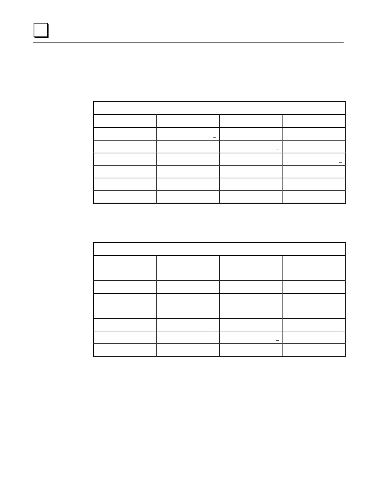
Table M-7. Volume Equivalents I
Units of Volume (Underlined Figures are Exact)
Units
Cubic Inches
Cubic Feet
Cubic Yards
1 cubic inch =
1
0.000 578 703 7
0.000 021 433 47
1 cubic foot =
1,728
1
0.037 037 04
1 cubic yard =
46,656
27
1
1 cubic centimeter =
0.061 023 74
0.000 035 314 67
0.000 001 307 951
1 cubic decimeter =
61.023 74
0.035 314 67
0.001 307 951
1 cubic meter
61,023.74
35.314 67
1.307 951
Table M-8. Volume Equivalents II
Units of Volume (Underlined Figures are Exact)
Units
Milliliters
Liters
Cubic Meters
(Cubic Centimeters)
(Cubic Decimeters)
1 cubic Inch =
16.387 064
0.016 387 064
0.000 016 387 064
1 cubic foot =
28,316.846 592
28.316 846 592
0.028 316 846 592
1 cubic yard =
764,554.857 984
764.554 857 984
0.764 554 857 984
1 cubic centimeter =
1
0.001
0.000 001
1 cubic decimeter =
1,000
1
0.001
1 cubic meter =
1,000,000
1,000
1
M-6
Series 90-30 PLC Installation and Hardware Manual - October 1999
GFK-0356P
Appendix
N 44A720084-001 EMI Line Filter
section level 1
figure_ap level 1
N
table_ap level 1
44A720084-001 Optional EMI Line Filter
Note
This product is not required on later versions of the Series 90-30 PLC. This
information is provided as a reference for those already using this product.
This item is still available for purchase from GE Fanuc.
Early versions of the Series 90-30 PLC and its associated hardware components were
designed primarily for use in industrial applications which are, in general, exempted
from FCC requirements. The AC power supply in those early PLCs may not comply
with FCC requirements in non-industrial applications for conducted EMI on AC power
lines. In a situation where it was desired to satisfy the FCC requirements for
non-industrial applications, a line filter was used in series with the AC power line input.
Later versions of the Series 90-30 PLC meet FCC requirements and do not require a
separate line filter.
A line filter that satisfies the FCC requirements for non-industrial applications is
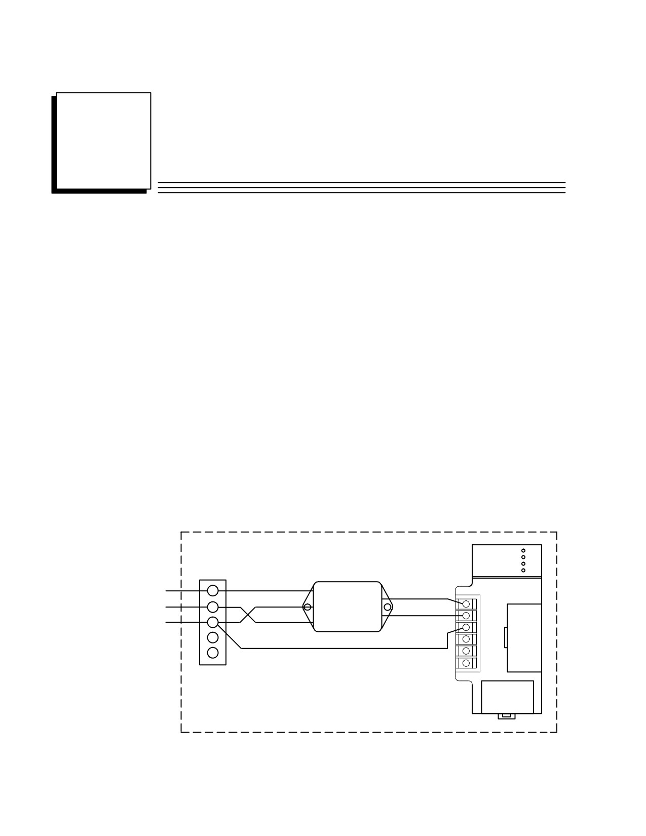
available from GE Fanuc as part number 44A720084-001. A wiring diagram for
connecting the line filter in a Series 90-30 PLC system is shown below.
POWER
TERMINAL
SUPPLY
STRIP
FILTER
BROWN
H
L
BROWN H
GRN/YEL
L
N
G
BLUE N
BLUE
N
G
N
G
NOTE:
FILTER CASE AND ENCLOSURE SHOULD ALSO
BE GROUNDED, IF POSSIBLE.
Figure N-1.
44A720084-001 Line Filter Connections to Series 90-30 Power Supply
GFK-0356P
N-1
N
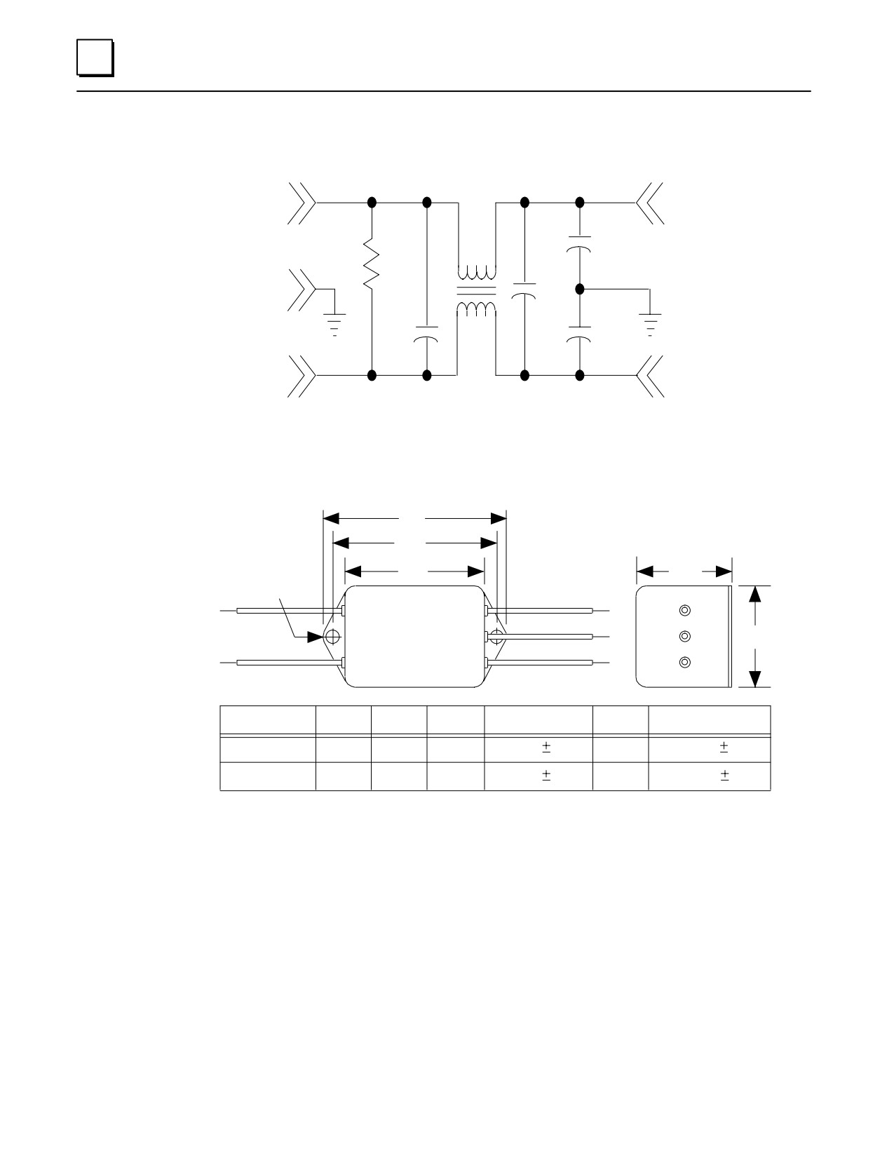
The equivalent circuit for the line filter is shown below. This is provided in case you
wish to specify or design a line filter as an alternative to the one mentioned above.
a43834
L
L
7.06
m H
.0033µf
1M
.33
µf
G
.33µf
.0033µf
7.06
m H
N
N
Figure N-2. Equivalent Circuit for 44A720084-001 Line Filter
44A720084-001 Line Filter Mounting Dimensions
E
a45626
D
Oty.2
A
C
Mtg. Holes
BLU
BLU
B
GRN/YEL
BRN
BRN
Dimension
A
B
C
D
E
Mounting Holes
Inches
2.09
1.84
1.29
2.375
.010
2.75
(2)
.187
.008
Millimeters
53.09
46.74
32.77
60.32
.25
69.85
(2)
4.75
.0.20
Figure N-3.
44A720084-001 Line Filter Mounting Dimensions
N-2
Series 90-30 PLC Installation and Hardware Manual - October 1999
GFK-0356P