FANUC Series 90-30 PLC. Installation and Hardware Manual (GFK-0356P) - page 14
H
· Multiply the input voltage times the current value times the estimated percent of on-time to
arrive at average power dissipation for that input.
· Repeat for all inputs on the module. To save time, you could determine if several inputs
were similar in current draw and on-time so that you would only have to make their
calculation once.
· Repeat these calculations for all Discrete Input modules in the rack.
Discrete Input Module Example:
The “Specifications” table for the IC693MDL240 16-Point Discrete 120 VAC Input Module in the
Series 90-30 PLC I/O Module Specification Manual, GFK-0898, gives the following information:
Input Current:
12 mA (typical) at rated voltage
Use this value for all of the input calculations for this module.
In this example, eight of the Input Module’s points are used for switches that, for normal operation,
stay on (closed) 100% of the time. These include the Emergency Stop, Over Temperature, Lube
Pressure OK, and similar switches.
Use the formula Average Power Dissipation = Input Voltage x Input Current (in Amps) x Percent
(expressed as a decimal) of on-time:
120 x .012 x 1.0 = 1.44 Watts per input
Then multiply this result by 8:
1.44 Watts x 8 inputs = 11.52 Watts total for the 8 inputs
Also in this example, two input points on this 16-point module are for the Control On and Pump
Start pushbuttons. Under normal conditions, these pushbuttons are only pressed once per day for
about one second - just long enough to start up the control and pump. Therefore, their effect on
our power calculation is negligible and we will assume a power dissipation of zero for them:
0.0 Watts total for 2 inputs
For the remaining six inputs of our sixteen point module, it is estimated that they will be on for an
average of 20% of the time. So the following calculation is made for these six inputs:
Using the formula of Average Power Dissipation = Input Voltage x Input Current (in Amps) x
Percent (expressed as a decimal) of on-time:
120 x .012 x 0.20 = 0.288 Watts per input
Then multiply this result by 6:
0.288 Watts x 6 inputs = 1.728 Watts total for the 6 inputs
GFK-0356P
Appendix H Series 90-30 Heat Dissipation
H-5

H
Finally, adding up the individual calculations, we get:
11.52 + 0.0 + 1.728 = 13.248 Watts for the module’s total input calculation
Step 5: Final Calculation
Once the individual power dissipations have been calculated, add them all to obtain total PLC heat
dissipation. Note that the PLC baseplate, analog input modules, and analog output modules have
been ignored in this procedure because their power dissipation values are negligible when
compared with the total. Also, since each Series 90-30 rack has its own power supply, each rack
should be calculated on an individual basis. The following table summarizes the final calculation:
Series 90-30 Rack Heat Dissipation Calculation Summary
Step
Description
Value (Watts)
1
Calculate total of dissipation values for all modules in the rack
2
Divide value obtained in Step 1 by 2 to obtain Power Supply value
3
Calculate total of all Output modules’ output dissipation values
4
Calculate total of all Input modules’ input dissipation values
5
Add the above four values to obtain the total dissipation of the rack
Other Information Related to Enclosure Sizing
The “Baseplates” chapter of this manual contains rack dimensions and minimum ventilation
clearance distances required around the racks. The “Cables” chapter contains clearance dimensions
for cables that mount on the front of modules.
H-6
Series 90-30 PLC Installation and Hardware Manual - October 1999
GFK-0356P
Appendix
Catalog Number to Publication Cross-Reference
I
Purpose
Manuals are not shipped with many of the Series 90-30 products; they must be
ordered separately. This appendix can help you identify the correct documentation to
order and use. Products are arranged in this appendix by categories such as Analog
I/O Modules, Baseplates, Communications Modules, etc. The category headings are
listed in alphabetical order. Modules that share common documentation are grouped
under a generic catalog number, such as IC693ALGxxx for the Analog I/O modules.
Note that you may not need every publication listed for a particular product. Your
need for some of the publications depends on your application. For example, if you
intend to use Logicmaster Programming software to configure and program your
PLC, you will not need the Control, VersaPro, or Hand Held Programmer manuals.
Or, if you are going to program your Programmable Coprocessor module using the C
computer language, you will not need the MegaBasic language manual. For your
convenience, a list of publication titles is included at the end of this data sheet.
Abbreviations Used
· HHP stands for Hand-Held Programmer.
· LM90 stands for Logicmaster, a DOS-based programming and configuration
software.
· Control stands for GE Fanuc Control, a Windows-based programming and
configuration software.
· SFC stands for Sequential Function Chart.
General System Information
90-30 PLC System
Installation: GFK-0356
Installation for Conformance to Standards: GFK-1179
Configuration Options:
· Configuration (HHP): GFK-0402
· Configuration (LM90): GFK-0466
· Configuration (Control): GFK-1295
· Configuration (VersaPro): GFK-1670
GFK-0356P
I-1

I
Analog I/O Modules
Task: Publication Number (revision letters not
Catalog Number
included)
All Analog Input,
Installation, Configuration, Specifications: GFK-0898
Output, and
Combination. Modules
(IC693ALGxxx)
Baseplates
All Series 90-30
Installation: GFK-0356
Baseplates
Configuration Options:
(IC693CHSxxx)
· Configuration (HHP): GFK-0402
· Configuration (LM90): GFK-0466
· Configuration (Control): GFK-1295
· Configuration (VersaPro): GFK-1670
Communications Modules
IC693BEM320
Installation, Configuration, User’s Guide: GFK-0631
I/O Link Interface
Module (slave)
IC693BEM321
Installation, Configuration, User’s Guide: GFK-0823
I/O Link Master
Module
IC693BEM330
Installation, Configuration, User’s Guide: GFK-1037
FIP Remote I/O
Related Publications:
Scanner Module
· Interfacing to Series 90-70: GFK-1038
· Hand Held Programmer User’s Manual: GFK-0402
· FIP Bus Controller User’s Manual: GFK-1213
IC693BEM340
Installation, Configuration, User’s Guide: GFK-1213
FIP Bus Controller
Related Publications:
Module
· Hand Held Programmer User’s Manual: GFK-0402
· FIP Bus Interface Unit: GFK-1175
· FIP Remote I/O Scanner: GFK-1037
I-2
Series 90-30 PLC Installation and Hardware Manual - October 1999
GFK-0356P

I
IC693CMM311
Installation, Configuration, User’s Guide: GFK-0582
Comm. Coprocessor
Module
IC693CMM321
Installation, Configuration, User’s Guide: GFK-1541
Ethernet Module
Programming Options:
· Ethernet Station Manager: GFK-1186
· Host Communications Toolkit, C/C++: GFK-0870
· Host Communications Drivers, MS Windows: GFK-
1026
· Host Communications Toolkit, Visual Basic: GFK-
1063
CPU Modules, CPU311-CPU341
Series 90-30 CPUs
Installation: GFK-0356
(IC693CPU311 -
Configuration and Programming Options:
IC693CPU341)
· Configuration and Programming (HHP): GFK-0402
· Configuration (LM90): GFK-0466
· Programming (LM90): GFK-0467
· SFC Programming (LM90): GFK-0854
· Configuration / Programming (VersaPro): GFK-1670
CPU Modules, CPU350 - CPU364
IC693CPU350
Installation: GFK-0356
CPU Module
Configuration and Programming Options:
· Configuration / Programming (HHP): GFK-0402
· Configuration (Control): GFK-1295
· Programming (Control): GFK-1411
· SFC Programming (Control): GFK-1385
· Configuration (LM90): GFK-0466
· Programming (LM90): GFK-0467
· SFC Programming (LM90): GFK-0854
· Configuration / Programming (VersaPro): GFK-1670
GFK-0356P
Appendix I Catalog Number to Publication Cross-Reference
I-3

I
IC693CPU351
· Installation: GFK-0356
IC693CPU352
· Serial Communications: GFK-0582
· Configuration and Programming Options:
CPU Modules
· Configuration / Programming (HHP): GFK-0402
· Configuration (Control): GFK-1295
· Programming (Control): GFK-1411
· SFC Programming (Control): GFK-1385
· Configuration (LM90): GFK-0466
· Programming (LM90): GFK-0467
· SFC Programming (LM90): GFK-0854
· Configuration / Programming (VersaPro): GFK-1670
IC693CPU360
Installation: GFK-0356
CPU modules
Configuration and Programming Choices:
· Configuration / Programming (HHP): GFK-0402
· Configuration (Control): GFK-1295
· Programming (Control): GFK-1411
· SFC Programming (Control): GFK-1385
· Configuration (LM90): GFK-0466
· Programming (LM90): GFK-0467
· SFC Programming (LM90): GFK-0854
· Configuration / Programming (VersaPro): GFK-1670
IC693CPU363
Installation: GFK-0356P or later
CPU Module
Configuration and Programming Options:
· Configuration and Programming (HHP): GFK-0402
· Configuration (Control): GFK-1295
· Programming (Control): GFK-1411
· SFC Programming (Control): GFK-1385
· Configuration (LM90): GFK-0466
· Programming (LM90): GFK-0467
· SFC Programming (LM90): GFK-0854
· Configuration / Programming (VersaPro): GFK-1670
· Serial Communications: GFK-0582
I-4
Series 90-30 PLC Installation and Hardware Manual - October 1999
GFK-0356P

I
IC693CPU364
Installation, Configuration, User’s Guide: GFK-1541
CPU Module
Specifications: GFK-0356P or later
Configuration and Programming Options:
· Configuration (Control): GFK-1295
· Programming (Control): GFK-1411
· SFC Programming (Control): GFK-1385
· Configuration (LM90): GFK-0466
· Programming (LM90): GFK-0467
· SFC Programming (LM90): GFK-0854
· Configuration / Programming (VersaPro): GFK-1670
· Ethernet Station Manager: GFK-1186
· Host Communications Toolkit, C/C++: GFK-0870
· Host Communications Drivers, MS Windows:
GFK-1026
· Host Communications Toolkit, Visual Basic:
GFK-1063
Digital Valve Driver Module
Installation and Specifications: GFK-0356P or later
IC693DVM300
Configuration Options:
· This module does not connect to PLC backplane;
therefore, it mounts in an unconfigured slot.
Discrete I/O Modules
Installation and Specifications: GFK-0898
All Discrete Input,
Configuration Options:
Output, and
Combination Modules
· Configuration (HHP): GFK-0402
(IC693MDLxxx)
· Configuration (LM90): GFK-0466
· Configuration (Control): GFK-1295
· Configuration (VersaPro): GFK-1670
GFK-0356P
Appendix I Catalog Number to Publication Cross-Reference
I-5

I
Genius Modules
IC693BEM331
Installation, Configuration, User Guide: GFK-1034
Genius Bus Controller
Related Publication:
· Genius I/O System User’s Manual: GEK-90486-1
· Genius Blocks User’s Manual: GEK-90486-2
IC693CMM301
Installation, Configuration, User Guide: GFK-0412
Genius Comm.
Related Publication:
Module
Genius I/O System User’s Manual: GEK-90486-1
IC693CMM302
Installation, Configuration, User Guide: GFK-0695
Genius Comm.
Related Publication:
Module + (Enhanced)
Genius I/O System User’s Manual: GEK-90486-1
Motion Modules
IC693APU300
Installation, Configuration, User Guide: GFK-0293
High Speed Counter
IC693APU301
Installation, Configuration, User’s Guide:
IC693APU302
· Standard Mode: GFK-0840
Axis Positioning
· Follower Mode: GFK-0781
Modules
· Motion Programming: GFK-0664
IC693DSM302
Installation, Configuration, User’s Guide (standard and
follower modes): GFK-1464
Digital Servo Module
Motion Programming: GFK-0664
IC693DSM314
Installation, Configuration, Local Logic, Motion
Programming User’s Guide (standard and follower modes):
Digital Servo Module
(Available late 1999)
(Manual will not be available until late 1999) GFK-1742
I-6
Series 90-30 PLC Installation and Hardware Manual - October 1999
GFK-0356P

I
Other Option Modules
IC693ADC311
Installation, Configuration, User’s Guide: GFK-0499
Alphanumeric
Programming Options:
Coprocessor Module
· Programming, PCOP Development Software:
GFK-0487
· ADS Display System Reference Manual: GFK-0641
IC693TCM302
Installation, Configuration, User’s Guide: GFK-1466
Temperature Control
Module
IC693APU305
Installation, Configuration, User’s Guide: GFK-1028
I/O Processor Module
IC693PCM300
Installation, Configuration, User’s Guide: GFK-0255
IC693PCM301
Programming Options:
IC693PCM311
· Programming, PCOP Development Software: GFK-
Programmable
0487
Coprocessor Modules
· Programming, MegaBasic: GFK-0256
· Programming, C Language: GFK-0771
· PCM C Function Library Reference: GFK-0772
· PCM Quick Reference Guide: GFK-0260
· PCOP Quick Reference Guide: GFK-0657
· TERMF Quick Reference Guide: GFK-0655
IC693PTM100
Installation, configuration, user’s guide: GFK-1734
Power Transducer
(Not available until late 1999.)
Module (PTM)
(Not available until
late 1999.)
GFK-0356P
Appendix I Catalog Number to Publication Cross-Reference
I-7
I
Power Supply Modules
All Series 90-30
Installation: GFK-0356 (Version P required for
Power Supply
preliminary information on IC693PWR332.)
Modules
Configuration Options:
(IC693PWRxxx)
· Configuration (HHP): GFK-0402
· Configuration (LM90): GFK-0466
· Configuration (Control): GFK-1295
· Configuration (VersaPro): GFK-1670
Programming Device
IC693PRG300
User’s Manual (using the HHP for configuration and
programming): GFK-0402
Hand-Held
Programmer
State Logic Products
IC693CSE311
Installation, Configuration, User’s Guide: GFK-1056
IC693CSE313
Programming Options:
IC693CSE323
· ECLiPS English Control Language: GFK-0732
IC693CSE331
· OnTOP User’s Guide:
GFK-0747
IC693CSE340
· OnTOP Troubleshooting Manual:
GFK-0750
State Logic CPUs
AD693SLP300
Installation, Configuration, User’s Guide: GFK-0726
State Logic Processor
Software Options:
(SLP) Module
· ECLiPS English Control Language: GFK-0732
· OnTOP Troubleshooting Manual: GFK-0750
AD693CMM301
Installation, Configuration, User’s Information Data Sheet:
State Logic Serial
GFK-1529
Communications
See also: GFK-1056
(SCM) Module
I-8
Series 90-30 PLC Installation and Hardware Manual - October 1999
GFK-0356P
I
Understanding Publication Revision Letters
When a GE Fanuc publication is revised, a letter is placed at the end of the
publication number. For example, in the publication number GFK-0356N, the
revision letter N at the end indicates the version of the manual. Manuals are revised
when there are changes or additions to the products or product lines covered in the
manual. Since this is a continual process, we decided that, except in a few special
cases, we would not include revision letters in this appendix in order to prevent
confusion. Therefore, when ordering these publications, ask for the latest version.
Note: Under normal circumstances, if a publication number does not have an ending
letter (suffix), such as GFK-1581, it is an indication that the publication has never
been revised.
Other Sources of Information
· GE Fanuc InfoLink PLC CD. This CD contains a collection of GE Fanuc
PLC manuals for Series 90-30, Series 90-70, Genius, VersaMax, etc. There is
also an InfoLink available for GE Fanuc CNC products. Be sure to specify
which one you need when ordering from your PLC distributor.
only an on-line version of the InfoLink CD, but also recently revised
publications, product revision histories, the GE Fanuc Automation Solutions
Catalog, and Third-Party product information.
Note: The information in this appendix is based upon Data Sheet GFK-1661.
GFK-0356P
Appendix I Catalog Number to Publication Cross-Reference
I-9

I
Publication No.
Titles of Series 90-30 Publications Cited in this Appendix
GFK-0255
Series 90 Programmable Coprocessor Module and Support Software User’s Manual
GFK-0256
MegaBasic Language Reference and Programmer’s Guide Reference Manual
GFK-0260
Programmable Coprocessor Module Quick Reference Guide
GFK-0293
Series 90-30 PLC High Speed Counter User’s Manual
GFK-0356
Series 90-30 PLC Installation Manual
GFK-0402
Hand-Held Programmer for Series 90-30/20/Micro PLC User’s Manual
GFK-0412
Series 90-30 Genius Communications Module User’s Manual
GFK-0466
Logicmaster 90, Series 90-30/20/Micro Programming Software User’s Manual
GFK-0467
Series 90-30/20/Micro PLC Reference Manual
GFK-0487
Series 90 PCM Development Software (PCOP) User’s Manual
GFK-0499
CIMPLICITY 90-ADS Alphanumeric Display System User’s Manual
GFK-0582
Series 90 PLC Serial Communications Driver User’s Manual
GFK-0631
Series 90-30 I/O Link Slave Interface User’s Manual
GFK-0641
CIMPLICITY 90-ADS Alphanumeric Display System Reference Manual
GFK-0655
Series 90 PCM Support Software (TERMF) Quick Reference Guide
GFK-0657
Series 90 PCM Development Software (PCOP) Quick Reference Guide
GFK-0664
Series 90-30 Axis Positioning Module Programmer’s Manual
GFK-0695
Series 90-30 Enhanced Genius Communications Module User’s Manual
GFK-0726
State Logic Processor For Series 90-30 PLC User’s Guide
GFK-0732
ECLiPS English Control Language Prog. System for Series 90-30 PLC User’s Guide
GFK-0750
OnTOP for Series 90-30 Online Troubleshooting and Operator Prog. User’s Manual
GFK-0771
C Programmer’s Toolkit for Series 90 PCMs User’s Manual
GFK-0772
PCM C Function Library Reference Manual
GFK-0781
Motion Mate APM for Series 90-30 PLC Follower Mode User’s Manual
GFK-0823
Series 90-30 I/O Link Master Module User’s Guide
GFK-0840
Power Mate APM for Series 90-30 PLC Standard Mode User’s Manual
GFK-0854
Series 90 Sequential Function Chart Programming Language User’s Manual
GFK-0870
Host Communications Toolkit for C/C++ Applications User’s Manual
GFK-0898
Series 90-30 PLC I/O Module Specifications Manual
GFK-1026
Host Drivers &Comm. Config. Software for Windows Environments User’s Manual
GDK-1028
Series 90-30 I/O Processor Module User’s Manual
GFK-1034
Series 90-30 Genius Bus Controller User’s Manual
GFK-1037
Series 90-30 FIP Remote I/O Scanner User’s Manual
GFK-1038
Series 90-70 FIP Bus Controller’s User’s Manual
GFK-1056
Series 90-30 State Logic Control System User’s Manual
GFK-1063
Host Communications Toolkit for Visual Basic Applications User’s Manual
GFK-1175
Field Control Distributed I/O & Control Sys. FIP Bus Interface Unit User’s Manual
GFK-1179
Installation Requirements for Conformance to Standards
GFK-1186
TCP/IP Ethernet Communications for the Series 90 PLC Station Manager Manual
GFK-1213
Series 90-30 FIP Bus Controller User’s Manual
GFK-1295
Using GE Fanuc Control
GFK-1385
GE Fanuc Control: Using the Sequential Function Chart Editor
GFK-1411
Series 90-30 System Manual
GFK-1464
Motion Mate DSM 302 for Series 90-30 PLCs User’s Manual
GFK-1466
Temperature Control Module for the Series 90-30 PLC User’s Manual
GFK-1541
TCP/IP Ethernet Communications for the Series 90 PLC User’s Manual
GFK-1670
VersaPro User’s Guide
GEK-90486-1
Genius I/O System and Communications User’s Manual
GEK-90486-2
Genius I/O Discrete and Analog Blocks User’s Manual
I-10
Series 90-30 PLC Installation and Hardware Manual - October 1999
GFK-0356P
GHIGHIGHI
Appendix
J Terminal Block Quick Connect Components
section level 1
figure_ap level 1
J
table_ap level 1
This appendix describes the optional terminal block components for Series 90-30 discrete I/O
modules. This system is referred to as the Terminal Block Quick Connect (TBQC) system.
The advantage of this system, is that it allows the listed discrete I/O modules to be quickly
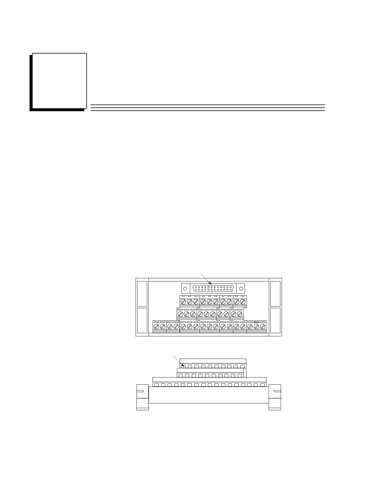
connected to TBQC terminal blocks. In this system, the TBQC terminal block (shown
below) is snapped onto a standard DIN-rail. Then, a factory-made cable is connected
between the terminal block’s connector and the I/O module’s connector. An I/O module
that has a terminal board instead of a connector is converted into a connector type using an
adapter faceplate.
The TBQC system is not recommended for use with Analog modules because it does not
meet the shielding recommendations for Analog module connections. (See the Series 90-30
PLC I/O Module Specifications Manual, GFK-0898, for Analog module wiring information.)
This appendix contains two sections, one for discrete 16-point I/O modules and one for
discrete 32-point I/O modules.
Connector (Male Pins)
a45586A
2
20
1
19
Top View
“Box” Terminals
Front View
Figure J-1. Typical TBQC Terminal Block
GFK-0356P
J-1

J
Terminal Block Quick Connect Components for 16-Point Modules
Installing a 16 point module typically takes 2 1/2 hours to wire from a PLC to a terminal
blocks or strip. With the TBQC, you simply snap the terminal block onto a DIN rail, remove
the I/O module’s terminal assembly, snap in the I/O faceplate, and connect the cable. This
reduces wiring time to about two minutes, thereby reducing wiring costs and errors.
Complete assemblies consist of a terminal block, an I/O Face Plate, and a cable.
Terminal Blocks
Terminal blocks have three rows of terminals, arranged in three levels, as shown in
Figure J-1. These terminal blocks feature an easy to use captive-screw, “rising cage” type
connection system. Catalog numbers for the terminal blocks and the modules they can
be used with are listed below.
Table J-1. TBQC Terminal Block Selection Table
Catalog
Use With
Module
Number
These Modules
Description
IC693ACC3291
IC693MDL240
Input, 120 VAC - 16 points
IC693MDL645
Input, 24 VDC Pos./Neg Logic- 16 points
IC693MDL646
Input, 24 VDC Pos./Neg,Logic,FAST - 16 points
IC693ACC330
IC693MDL740
Output, 12/24VDC Pos Logic, 0.5A - 16 points
IC693MDL742
Output, 12/24VDC Pos Logic ESCP, 1A- 16 points
IC693ACC331
IC693MDL741
Output, 12/24 VDC Neg Logic, 0.5A- 16 points
IC693ACC332
IC693MDL940
Output, Relay, N.O. - 16 points
IC693ACC333
IC693MDL340
Output, 120 VAC, 0.5A - 16 points
1
This Terminal Block may be used with most I/O modules that have up to 16 I/O points (can
not be used with 32 point modules). Jumpers may have to be added; for details of required
wiring connections, refer to module specifications in GFK-0898.
Cable Current Rating
Each conductor in these 24-conductor cables has a current rating of 1.2 Amps. If using
these cables with a 16-point Output module with a higher output current rating, you
must use the lower value of 1.2 Amps for the maximum load current rating . If you have
field devices that require more than 1.2 Amps, do not use a TBQC assembly - use the
standard Terminal Board that comes with the module instead.
J-2
Series 90-30 PLC Installation and Hardware Manual - October 1999
GFK-0356P
J
Cable Selection and Cross-Reference
Three cables are available for connecting between the module’s faceplate connector and
the terminal block. The only difference in these cables is their length. These cables have
right-angle connectors on the module end to minimize the space required in front of the
modules. These three cables replace three obsolete cables that had straight connectors.
Use the following table to select the correct cable.
Cable Catalog
Description
Replaces Obsolete
Number
Cable Number
IC693CBL330
CBL Assembly, 24-pin, 90 Deg, Right Side,
IC693CBL321
1.0 Meter length
IC693CBL332
CBL Assembly, 24-pin, 90 Deg, Right Side,
IC693CBL322
2.0 Meter length
IC693CBL334
CBL Assembly, 24-pin, 90 Deg, Right Side,
IC693CBL323
0.5 Meter length
I/O Face Plate for 16-Point Modules
The I/O Face Plate (catalog number IC693ACC334) has a 24-pin connector, which
provides the connection to the applicable terminal block through a 0.5, 1, or 2 meter
cable. This face plate replaces the standard terminal board on the listed modules.
I/O Face Plate Installation
Step 1: Install terminal block assembly on DIN rail
Place the terminal block over the desired location on the DIN rail and snap into place.
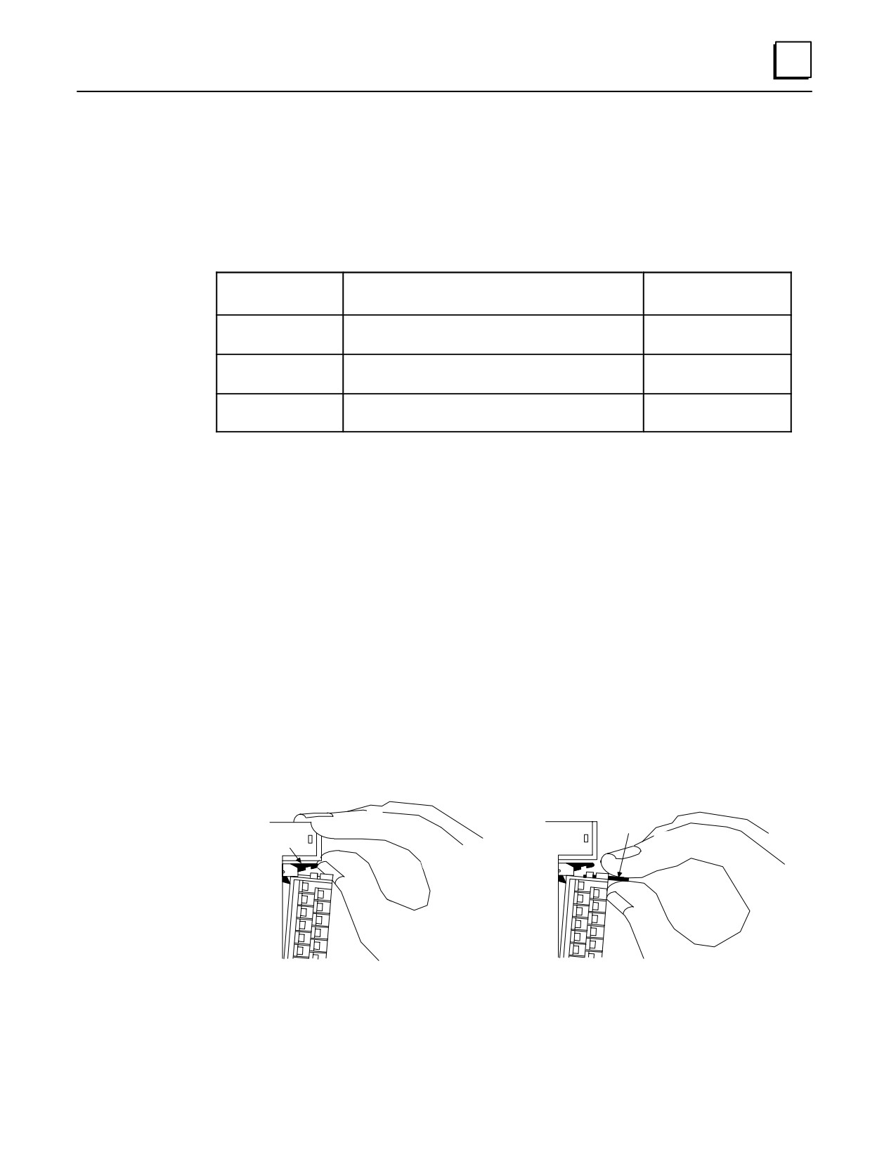
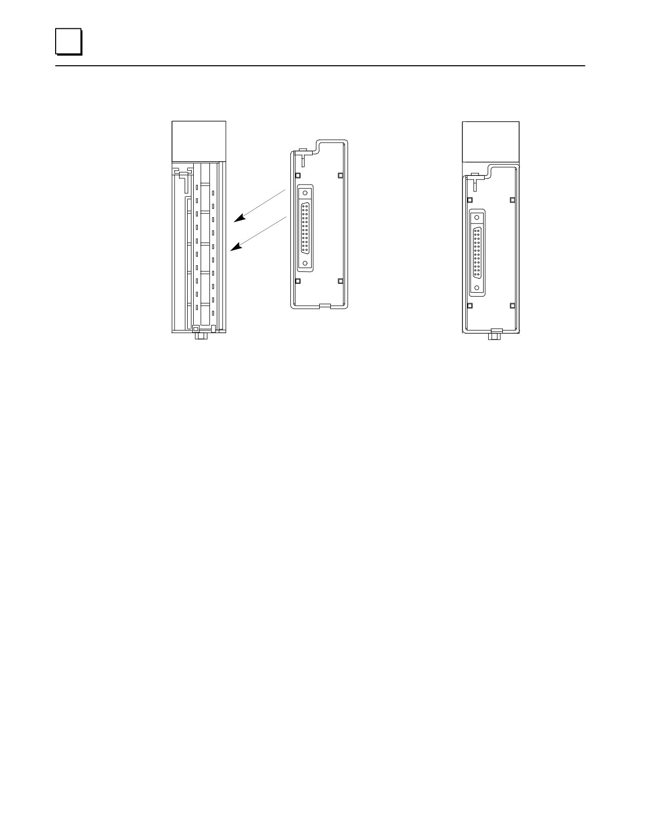
Step 2: Remove 20-pin terminal assembly from module
a43061
a43715
ÎÎ
Î
PULL
TAB
JACKING
LEVER
ÎÎ
ÎÎ
ÎÎ
Î
ÎÎÎ
ÎÎ
ÎÎ
ÎÎÎ
ÎÎÎÎ
Î
ÎÎÎÎ
Open the plastic terminal board cover.
Grasp pull-tab towards you until contacts have
separated from module housing and hook has
Push up on the jacking lever to release
disengaged for full removal.
the terminal block.
GFK-0356P
Appendix
J Terminal Block Quick Connect Components
J-3
J
Step 3: Snap I/O Face Plate assembly on module
a47118
A1 2 3 4 5 6 7 8
A1 2 3 4 5 6 7 8
B1 2 3 4 5 6 7 8F
B1 2 3 4 5 6 7 8F
Installing the I/O Face Plate
Module with I/O Face Plate Installed
Step 4: Connect cable to connector on terminal block
Finally, connect the selected length cable from the connector on the I/O Face Plate to the
connector on the interposing terminal block.
Module Wiring Information
Refer to GFK-0898, Series 90-30 PLC I/O Module Specifications Manual for wiring
connections for each module.
Cable Information
Data sheets for the cables are found in the “Cables” chapter of this manual.
J-4
Series 90-30 PLC Installation and Hardware Manual - October 1999
GFK-0356P
J
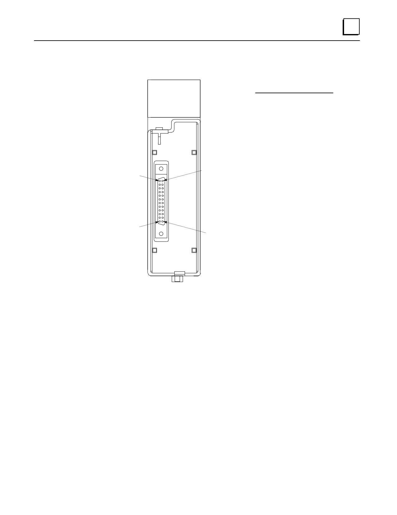
Connector Pin Orientation and Connection to Module Terminal
a47119
Module
Connector
Terminal #
Pin#
A1 2 3 4 5 6 7 8
1
B1
B1 2 3 4 5 6 7 8F
2
A1
3
B2
4
A2
5
B3
6
A3
7
B4
8
A4
9
B5
10
A5
. . . . . . . . B6 (N.C.)
Pin B1
. . . . . . . . A6 (N.C.)
Pin A1
. . . . . . . . B7 (N.C.)
. . . . . . . . A7 (N.C.)
11
B8
12
A8
13
B9
14
A9
15
B10
16
A10
Pin A12
17
B11
Pin B12
18
A11
19
B12
20
A12
Connector Pin Orientation
Figure J-2. TBQC Faceplate
Terminal Block Information
Terminal block data sheets are found on the next several pages.
GFK-0356P
Appendix
J Terminal Block Quick Connect Components
J-5
J
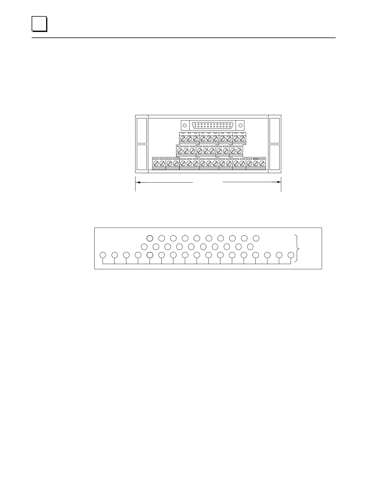
IC693ACC329 TBQC Terminal Block
Use with the following 16-point I/O modules:
IC693MDL240
IC693MDL645
IC693MDL646
a45586
2
20
1
19
Maximum wire size
per terminal: one
#14 AWG (2.10 mm2)
Width
4.44” (112mm)
Height (all blocks)
2.25” (57mm)
Depth (all blocks)
1.7716” (45mm)
2
4
6
8
10
12
14
16
18
20
TERMINAL
1
3
5
7
9
11
13
15
17
19
BLOCK
C
C
C
C
C
C
C
C
C
C
C
C
C
C
C
C
C
(See Note 1
Below)
Figure J-3. IC693ACC329 TBQC Terminal Block
Note
The common row terminals (labeled with the letter C) are provided for wiring
convenience. Their use is optional. They are electrically isolated from the
numbered terminals. You may use them as is, or jumper them to a numbered
terminal. Refer to GFK-0898, Series 90-30 PLC I/O Module Specifications Manual for
wiring diagrams of the modules.
Mounting
These terminal blocks are mounted on a standard, user-supplied 35 mm DIN-rail.
J-6
Series 90-30 PLC Installation and Hardware Manual - October 1999
GFK-0356P
J
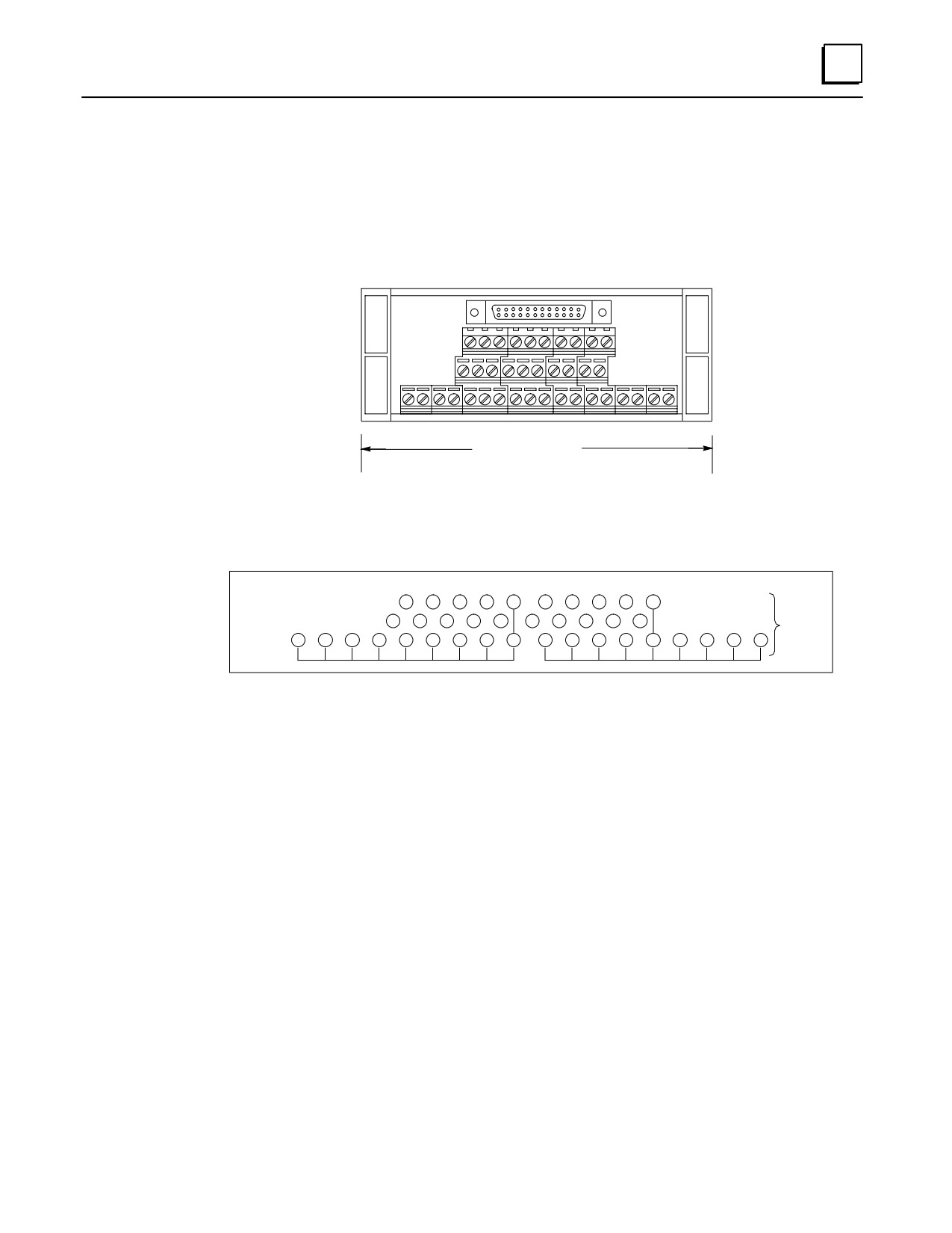
IC693ACC330 TBQC Terminal Block
Use with the following 16-point I/O modules:
IC693MDL740
IC693MDL742
a45587
2
20
1
19
Maximum wire size
per terminal: one
#14 AWG (2.10 mm2)
Width
4.64” (117.86mm)
Height (all blocks)
2.25” (57mm)
Depth (all blocks)
1.7716” (45mm)
2
4
6
8
10
12
14
16
18
20
TERMINAL
1
3
5
7
9
11
13
15
17
19
BLOCK
C
C
C
C
C
C
C
C
C
C
C
C
C
C
C
C
C
C
Figure J-4. IC693ACC330 TBQC Terminal Block
Note
Refer to GFK-0898, Series 90-30 PLC I/O Module Specifications Manual for required
wiringconnections.
Mounting
These terminal blocks are mounted on a standard, user-supplied 35 mm DIN-rail.
GFK-0356P
Appendix
J Terminal Block Quick Connect Components
J-7
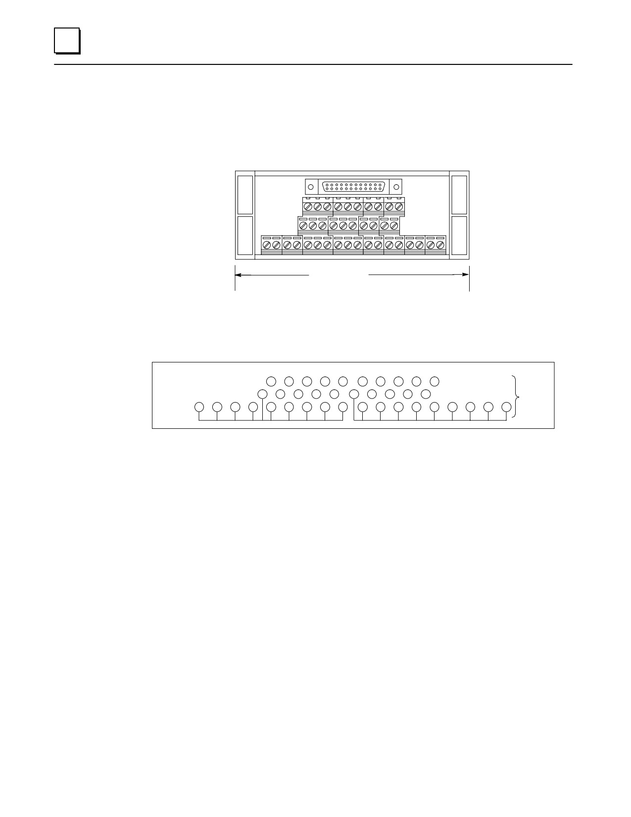
J
IC693ACC331 TBQC Terminal Block
Use with the following 16-point I/O module:
IC693MDL741
a45588
2
20
1
19
Maximum wire size
per terminal: one
#14 AWG (2.10 mm2)
Width
4.64” (117.86mm)
Height (all blocks)
2.25” (57mm)
Depth (all blocks)
1.7716” (45mm)
2
4
6
8
10
12
14
16
18
20
1
3
5
7
9
11
13
15
17
19
TERMINAL
BLOCK
+
+
+
+
+
+
+
+
+
+
+
+
+
+
+
+
+
+
Figure J-5. IC693ACC331 TBQC Terminal Block
Note
Refer to GFK-0898, Series 90-30 PLC I/O Module Specifications Manual for required
wiringconnections.
Mounting
These terminal blocks are mounted on a standard, user-supplied 35 mm DIN-rail.
J-8
Series 90-30 PLC Installation and Hardware Manual - October 1999
GFK-0356P
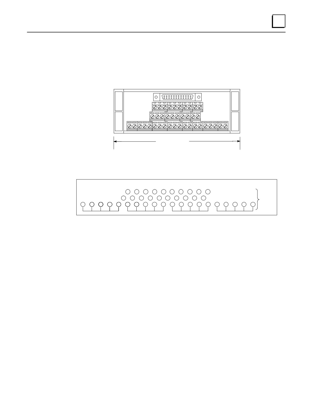
J
IC693ACC332 TBQC Terminal Block
Use with the following 16-point I/O module:
IC693MDL940
a45589
2
20
1
19
Maximum wire size
per terminal: one
#14 AWG (2.10 mm2)
Width
5.04” (128mm)
Height (all blocks)
2.25” (57mm)
Depth (all blocks)
1.7716” (45mm)
2
4
6
8
10
12
14
16
18
20
1
3
5
7
9
11
13
15
17
19
TERMINAL
BLOCK
C
C
C
C
C
C
C
C
C
C
C
C
C
C
C
C
C
C
C
C
(See Note 1
Below)
Figure J-6. IC693ACC332 TBQC Terminal Block
Note
The common row terminals (labeled with the letter C) are provided for wiring
convenience. Their use is optional. They are electrically isolated from the
numbered terminals. You may use them as is, or jumper them to a numbered
terminal. Refer to GFK-0898, Series 90-30 PLC I/O Module Specifications Manual for
wiring diagrams of the modules.
Mounting
These terminal blocks are mounted on a standard, user-supplied 35 mm DIN-rail.
GFK-0356P
Appendix
J Terminal Block Quick Connect Components
J-9
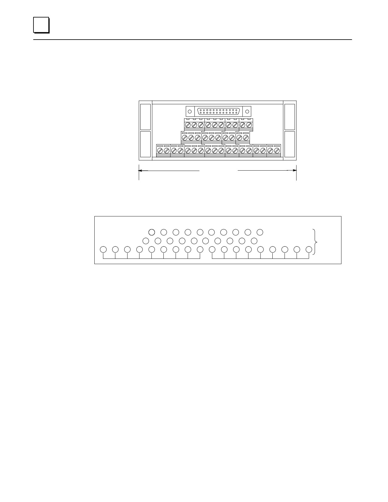
J
IC693ACC333 TBQC Terminal Block
Use with the following 16-point I/O module:
IC693MDL340
a45590
2
20
1
19
Maximum wire size
per terminal: one
#14 AWG (2.10 mm2)
Width
4.64” (117.86mm)
Height (all blocks)
2.25” (57mm)
Depth (all blocks)
1.7716” (45mm)
2
4
6
8
10
12
14
16
18
20
TERMINAL
1
3
5
7
9
11
13
15
17
19
BLOCK
N
N
N
N
N
N
N
N
N
N
N
N
N
N
N
N
N
N
(See Note 1
Below)
Figure J-7. IC693ACC333 TBQC Terminal Block
Note
The neutral row terminals (labeled with the letter N) are provided for wiring
convenience. Their use is optional. They are electrically isolated from the
numbered terminals. You may use them as is, or jumper them to a numbered
terminal. Refer to GFK-0898, Series 90-30 PLC I/O Module Specifications Manual for
wiring diagrams of the modules.
Mounting
These terminal blocks are mounted on a standard, user-supplied 35 mm DIN-rail.
J-10
Series 90-30 PLC Installation and Hardware Manual - October 1999
GFK-0356P
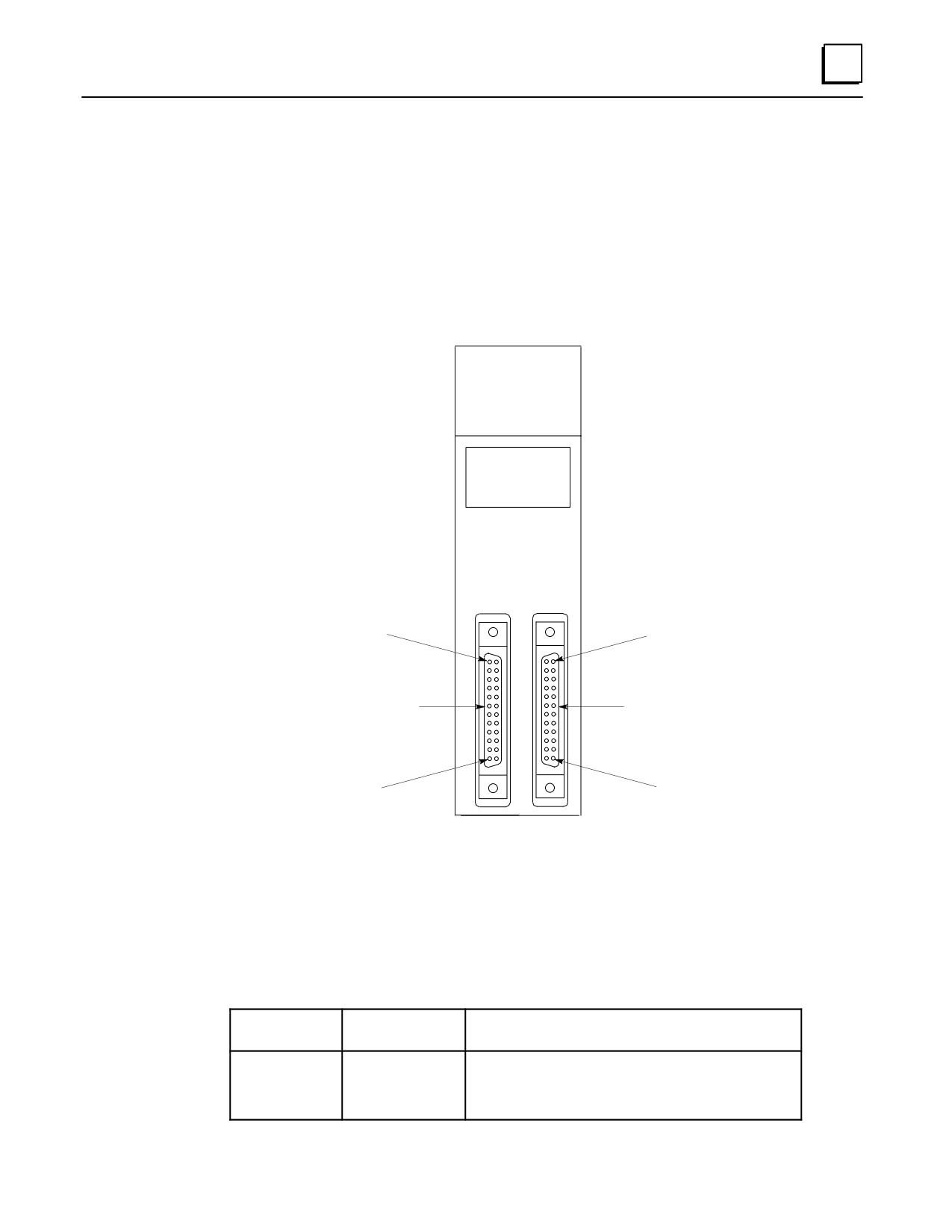
J
Terminal Block Quick Connect Components for 32-Point Modules
The 32-point modules do not require a new faceplate since they are equipped with a
dual-connector faceplate as a standard feature. Since each module has two 24-pin
connectors, they each require two cables and two terminal blocks. Also, since the
modules’ two connectors are oriented differently (see example in figure below), the two
cables are different. One is called a “right side” cable and the other, a “left side” cable.
Note: These terminal blocks will not work with the 32-point I/O modules that have
50-pin connectors.
A1 2 3 4 5 6 7 8
F
B1 2 3 4 5 6 7 8
C1 2 3 4 5 6 7 8
D1 2 3 4 5 6 7 8
INPUT
5/12 VDC
POS/NEG LOGIC
3.0 mA/Pt at 5VDC
8.5 mA/Pt at 12VDC
CD
AB
Pin B12
Pin B1
“Left Side”
“Right Side”
Connector
Connector
Pin B1
Pin B12
Figure J-8. IC693MDL654 32-Point Module
Terminal Block
Terminal blocks have three rows of terminals, arranged in three levels, as shown in
Figure J-1. The terminals feature an easy to use captive-screw, “rising cage” type
connection system. Catalog numbers for the terminal block and the modules it can be
used with are listed below.
Catalog
Use With
Module
Number
These Modules
Description
IC693ACC337
IC693MDL654
Input, 5/12 VDC (TTL) Pos/Neg Logic- 32 points
IC693MDL655
Input, 24 VDC Pos/Neg Logic - 32 points
IC693MDL752
Output, 5/24 VDC Neg Logic-32 points
IC693MDL753
Output, 12/24VDC Pos Logic, 0.5A - 32 points
GFK-0356P
Appendix
J Terminal Block Quick Connect Components
J-11

J
Cable Selection and Cross-Reference
Six cables are available for connecting between the modules’ faceplate connectors and
the terminal blocks. These cables have right-angle connectors on the module end to
minimize the space required in front of the modules. These six cables replace three
obsolete cables that had straight connectors. Since the modules’ two connectors are
oriented differently (see previous figure), a right-side and left-side cable is required. Use
the following table to select the correct cables. The table also lists cable kits that consist
of a pair of same length, right side and left side cables.
Cable Current Rating
Each conductor in these 24-conductor cables has a current rating of 1.2 Amps, which is
more than adequate to handle the current requirement of any of the 32-point I/O
modules listed in the previous table.
Cable Catalog
Cable Description
Replaces Obsolete
Number
and Length
Cable Number
IC693CBL329
Dual 24-pin, 90 deg. connectors, Left Side
IC693CBL321
Cable length = 1.0 Meter
IC693CBL330
Dual 24-pin, 90 deg. connectors, Right Side
IC693CBL321
Cable length = 1.0 Meter
IC693CBL331
Dual 24-pin, 90 deg. connectors, Left Side
IC693CBL322
Cable length = 2.0 Meters
IC693CBL332
Dual 24-pin, 90 deg. connectors, Right Side
IC693CBL322
Cable length = 2.0 Meters
IC693CBL333
Dual 24-pin, 90 deg. connectors, Left Side
IC693CBL323
Cable length = 0.5 Meter
IC693CBL334
Dual 24-pin, 90 deg. connectors, Right Side
IC693CBL323
Cable length = 0.5 Meter
Cable Kits
IC693CBK002
Cable Kit. Includes both the IC693CBL329 (left side) and
IC693CBL330 (right side) cables
IC693CBK003
Cable Kit. Includes both the IC693CBL331 (left side) and
IC693CBL332 (right side) cables
IC693CBK004
Cable Kit. Includes both the IC693CBL333 (left side) and
IC693CBL334 (right side) cables
Cable Data
Data sheets for these cables are found in the “Cables” chapter of this manual.
Terminal Block Data
Data for the terminal block is found on the next page.
J-12
Series 90-30 PLC Installation and Hardware Manual - October 1999
GFK-0356P
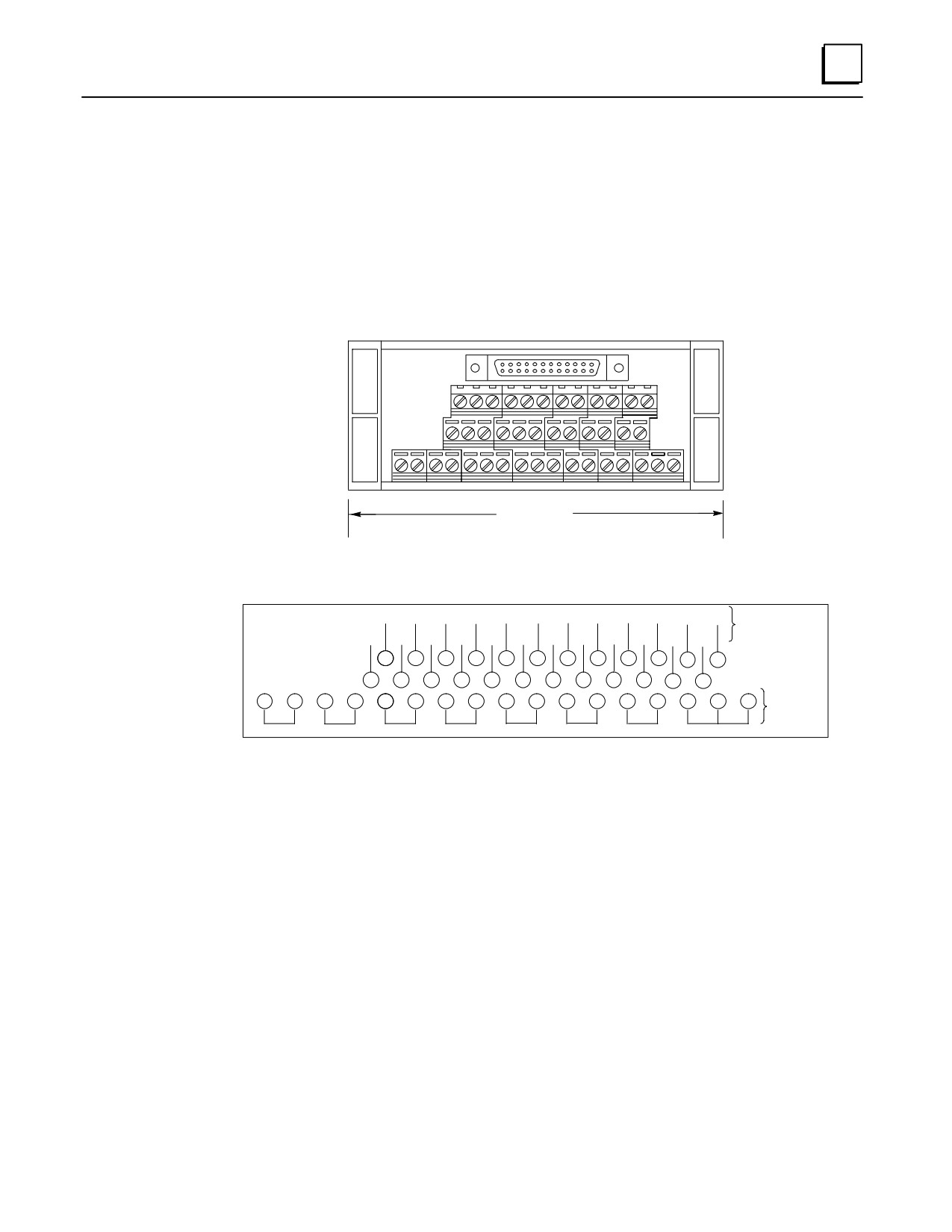
J
IC693ACC337 TBQC Terminal Block
Use with the following 32-point I/O modules (2 required per module):
IC693MDL654
IC693MDL655
IC693MDL752
IC693MDL753
2
24
1
23
Maximum wire size
per terminal: one
#14 AWG (2.10 mm2)
Width
4.45” (112mm)
Height (all blocks)
2.15” (57mm)
Depth (all blocks)
1.7716” (45mm)
A1
A2
A3
A4
A5
A6
A7
A8
A9
A10
A11
A12
24-Pin
Connector
B1
B2
B3
B4
B5
B6
B7
B8
B9
B10
B11
B12
2
4
6
8
10
12
14
16
18
20
22
24
TERMINAL
1
3
5
7
9
11
13
15
17
19
21
23
BLOCK
C
C
C
C
C
C
C
C
C
C
C
C
C
C
C
C
C
(See Note 1
Below)
Figure J-9. IC693ACC337 TBQC Terminal Block
Note
The common row terminals (labeled with the letter C) are provided for wiring
convenience. Their use is optional. They are electrically isolated from the
numbered terminals. You may use them as is, or jumper them to a numbered
terminal. Refer to GFK-0898, Series 90-30 PLC I/O Module Specifications Manual for
wiring diagrams of the modules.
Mounting
These terminal blocks are mounted on a standard, user-supplied 35 mm DIN-rail.
GFK-0356P
Appendix
J Terminal Block Quick Connect Components
J-13
Appendix
K SNP Multidrop
section level 1
figure_ap level 1
K
table_ap level 1
SNP Multidrop Overview
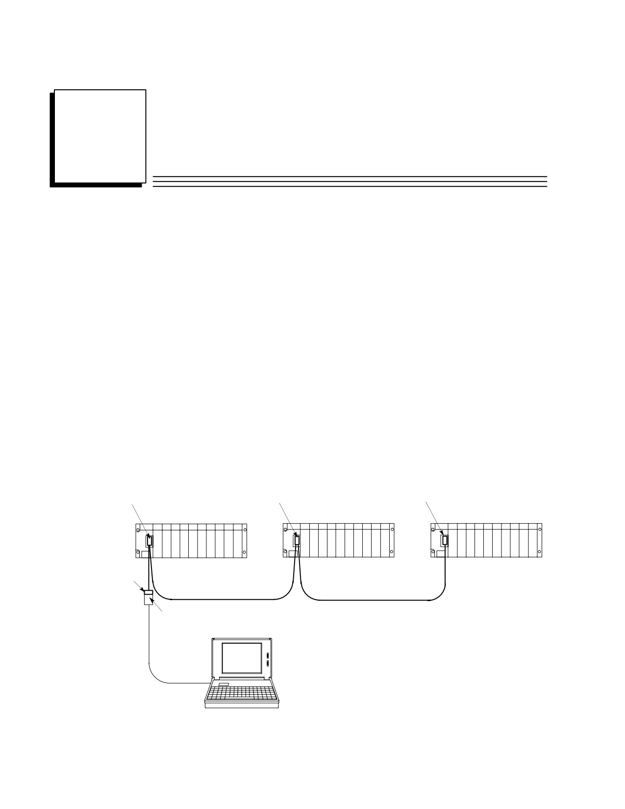
As used in this appendix, the term “SNP Multidrop” refers to a system that allows a
programmer (called the “master or host”), such as a personal computer running GE
Fanuc programming software, to connect to two or more PLCs or intelligent Option
modules (called “slaves“) via a single connection. In this arrangement the programmer
is able to program, configure, test, troubleshoot, etc., any one of the multidropped
devices from one connection point.
Physically, a typical SNP multidrop system consists of a programmer and two or more
PLCs interconnected by a “daisy-chain“ type cabling arrangement, as shown in the
figure below. It is necessary to assign each slave device (PLC or Option module) a
unique SNP (Series Ninety Protocol) address, using programming software such as
Logicmaster or VersaPro. The SNP address is used by the programmer to designate
which PLC it will communicate with. The SNP protocol uses the RS-422
communications standard. Note that the PLCs or Option modules do not communicate
with each other over the multidrop system. They only communicate with the
programmer. And only one device, the one designated by the programmer, can
communicate with the programmer at a time.
Multidrop Connector
Multidrop Connector
Multidrop Connector
15-pin Male
15-pin Male
15-pin Male
Series 90-30 PLC (slave)
Series 90-30 PLC (slave)
Series 90-30 PLC (slave)
Multidrop
Connector
15-pin Fe-
male
Multidrop Cable
Multidrop Cable
IC690ACC901
Miniconverter
Serial Cable
Programmer (master)
Figure K-1. Series 90-30 Multidrop Example
K-1
GFK-0356P

K
Multidrop Cables
There are two sources of multidrop cables:
GE Fanuc cable, catalog number IC690CBL714A - This pre-made cable can be
purchased for applications where the PLCs are mounted in the same cabinet, such as
in the case of redundant systems. The length of this cable is 40 inches (1 meter).
Custom built - For PLCs that are more than 40 inches (1 meter) apart, it is necessary
to build a custom length cable. The specifications are provide below.
Limitations
The maximum cable length between a master (programmer) and slave device (PLC
or Option module) in a multidrop system is 4,000 feet (1,219 meters).
The maximum number of slave devices is limited to eight.
Cable and Connector Specifications
The cable assembly presents one of the most common causes of communication failure.
For best performance, construct the cable assemblies using the recommended connector
parts and specifications.
Table K-1. Connector and Cable Specifications
Item
Description
Series 90 PLC: Serial (RS-422) port with metric hardware
Connectors
Connector: 15-pin male, D-Subminiature Type, Cannon DA15S (solder pot)
Hood: AMP 207470-1 connector shell
Hardware Kit: AMP 207871-1 Kit includes 2 metric screws and 2 screw clips
Miniconverter: For connecting to IC690ACC901 miniconverter
Connector:
15-pin female, DB15F,
Hood: AMP #207470-1 or equivalent
M3 Latchblocks: AMP #208101 or equivalent
Computer grade, 24 AWG (.22 mm2), minimum with overall shield
Catalog Numbers: Belden 9505, Belden 9306, Belden 9832
Cable
These cables provide acceptable operation for data rates up to 19.2 Kbps
as follows:
RS-422/RS-422:
4000 feet (1200 meters) maximum length. Must not
exceed the maximum RS-422 Common Mode specifi-
cation of +7V to -7V. Isolation at the remote end may
be used to reduce or eliminate Common Mode voltages.
When using RS-422/RS-422, the twisted pairs should be matched so that both
transmit signals make up one twisted pair and both receive signals make up the
other twisted pair. If this is ignored, cross-task resulting from the mismatching
will affect the performance of the communications system.
When routing communication cables outdoors, transient suppression devices can
be used to reduce the possibility of damage due to lightning or static discharge.
Care should be exercised that all connected devices are grounded to a common point.
Failure to do so could result in damage to the equipment.
K-2
Series 90-30 PLC Installation and Hardware Manual - October 1999
GFK-0356P
K
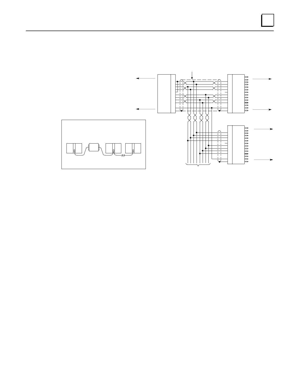
MultiDrop Cable Wiring Diagram
RS-422
MAKE CONNECTIONS
INSIDE D-CONNECTORS
PIN
PIN
DCD ( A )
2
2
DCD ( B )
3
3
RD ( A’ )
10
12
SD ( A )
RD ( B’ )
11
13
SD ( B )
SD ( A )
12
10
RD ( A’ )
To Miniconverter on
SD ( B )
13
11
RD ( B’ )
Programmer Serial
RT
9
9
RD
To First Slave PLC
Cable
CTS ( A’ )
15
6
RTS ( A )
CTS ( B’ )
8
14
RTS ( B )
RTS ( A )
6
15
CTS ( A’ )
RTS ( B )
14
8
CTS ( B’ )
+5V
5
5
+5V
0V
7
7
0V
SHLD
1
1
SHLD
15- PIN
15- PIN
FEMALE
MALE
NOTE
WHEN WIRING RS-422 /485 MULTIDROP CABLES, REFLECTIONS ON THE
PIN
TRANSMISSION LINE CAN BE REDUCED BY CONFIGURING THE CABLE IN A
2
DAISY CHAIN FASHION, AS SHOWN BELOW.
3
12
SD ( A )
13
SD ( B )
MINI-
FIRST SLAVE
LAST SLAVE
10
RD ( A’ )
PROGRAMMER CONVERTER
STATION (PLC)
STATION (PLC)
11
RD ( B’ )
*
9
RD
To Second Slave PLC
ÎÎ
PLC 15-PIN CONNECTOR
6
RTS ( A )
SERIES 90-30 LOCATED
14
RTS ( B )
ON POWER SUPPLY
SERIES 90-70 LOCATED
15
CTS ( A’ )
ÎÎ
ON THE CPU BOARD
8
CTS ( B’ )
5
+5V
ALSO IT IS RECOMMENDED TO MAKE ANY NECESSARY CONNECTIONS
7
0V
INSIDE THE CABLE CONNECTOR TO BE MOUNTED ON THE PLC. IT IS
1
SHLD
NOT RECOMMENDED TO USE TERMINAL STRIPS TO OTHER TYPES OF
15- PIN
CONNECTORS ALONG THE LENGTH OF THE TRANSMISSION LINE.
TO OTHER PLC’s
MALE
If applicable
* TERMINATION RESISTANCE FOR THE RECEIVE DATA (RD) SIGNAL NEEDS TO BE CONNECTED ONLY ON UNITS AT THE END OF THE LINES. THIS TERMINATION IS MADE
ON THE SERIES 90 PLC PRODUCTS BY CONNECTING A JUMPER BETWEEN PIN 9 AND PIN 10 INSIDE THE 15-PIN D-SHELL WITH THE FOLLOWING EXCEPTION. FOR SERIES
90-70 PLCs, CATALOG NUMBERS IC697CPU731 AND IC697CPU771, THE TERMINATION FOR RD AT THE PLC IS IMPLEMENTED BY A JUMPER BETWEEN PIN 9 AND PIN 11.
GROUND POTENTIAL: MULTIPLE UNITS, NOT CONNECTED TO THE SAME POWER SOURCE, MUST HAVE COMMON GROUND POTENTIALS OR GROUND ISOLATION FOR PROPER
OPERATION OF THIS SYSTEM.
Figure K-2. Multidrop Cable Wiring Diagram
GFK-0356P
Appendix K SNP Multidrop
K-3
K
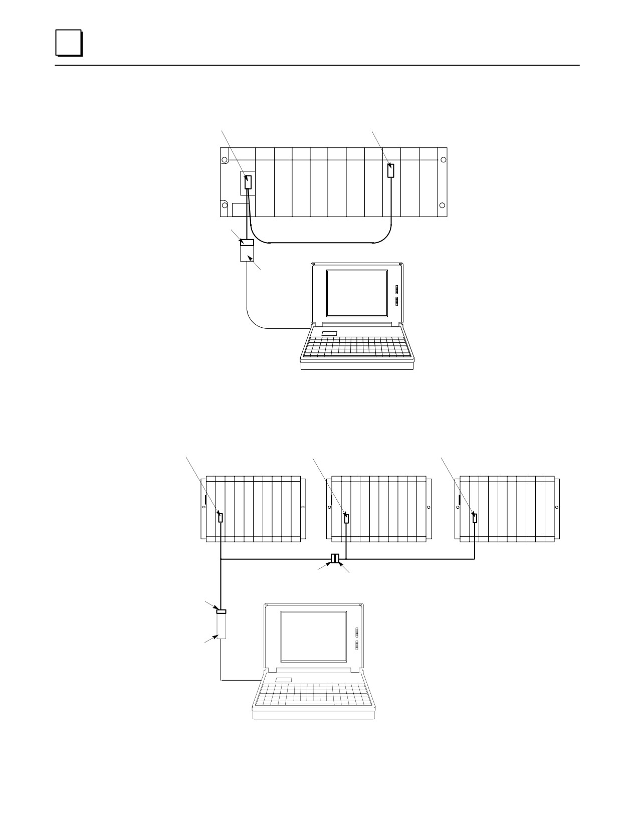
SNP Multidrop Examples
Conn. B
Conn. C to APM Comm. Port
Series 90-30 PLC
PS
CPU
APM
Conn. A
IC690CBL714A Cable
IC690ACC901
Miniconverter
Serial Cable
Figure K-3. Connecting CPU and APM to Programmer with IC690CBL714A Cable
a47100
Conn. B
Conn. B
Conn. C
PLC A
PLC
B
PLC C
C
C
C
P
P
P
U
U
U
IC690CBL714A
IC690CBL714A
Conn. C
Conn. A
Conn. A
RS-232/422
Converter
Figure K-4. Multidrop Arrangement for Series 90-70 TMR Redundant System
K-4
Series 90-30 PLC Installation and Hardware Manual - October 1999
GFK-0356P
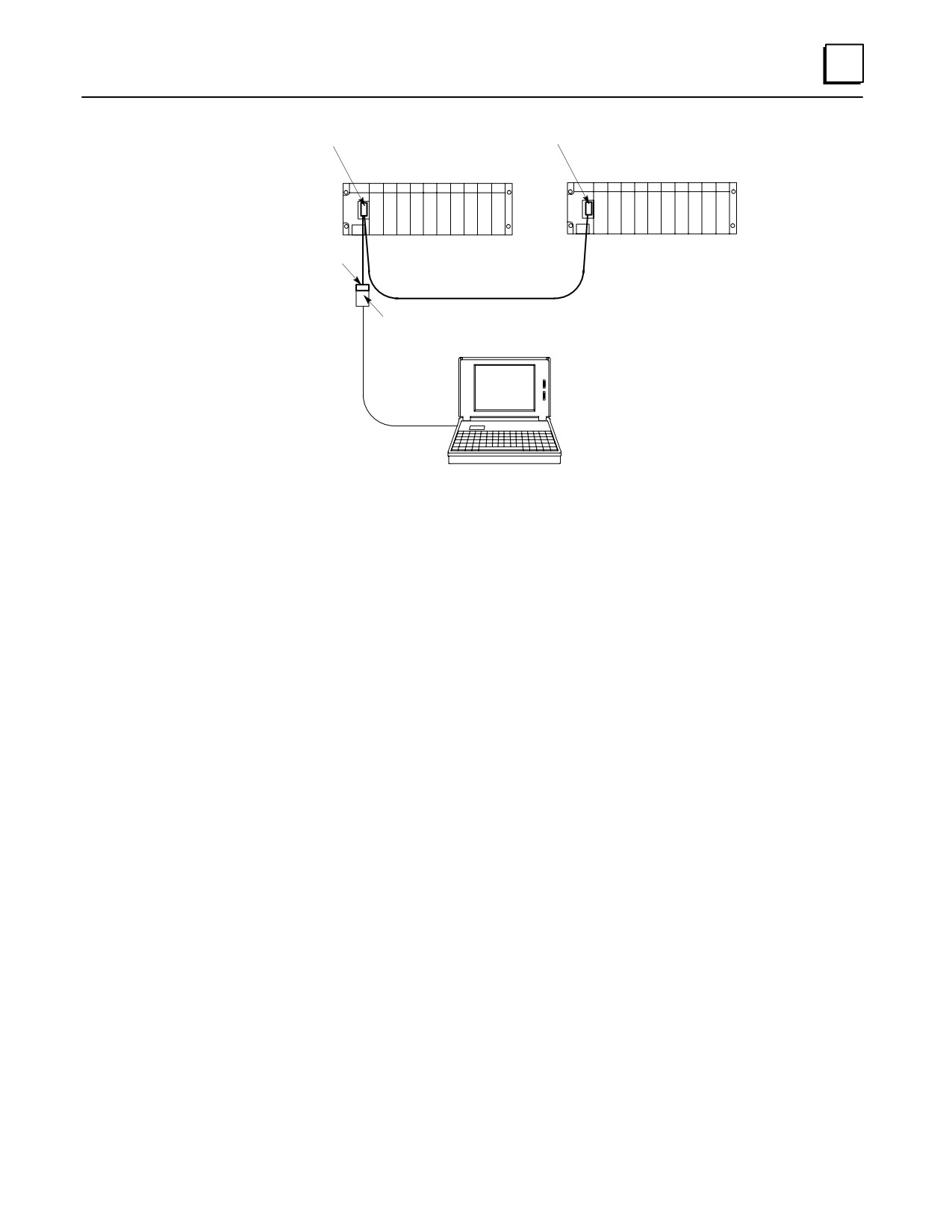
K
Conn. B
Conn. C
Series 90-30 PLC
Series 90-30 PLC
Conn. A
IC690CBL714A Cable
IC690ACC901
Miniconverter
Serial Cable
Figure K-5. Multidrop Arrangement for Series 90-30 Redundant System
Configuring and Connecting a Programmer to a Multidrop Network
Each slave device on a multidrop system must have its own unique SNP ID
(identification). The SNP ID assignment is made with a programmer running GE Fanuc
programming software, or with the Hand Held Programmer. Logicmaster, Control, or
Versa Pro software packages all can be used for this purpose. The following example
uses Logicmaster. Please see your software user ’s manual or on-line help screens for
instructions. Regardless of what software you use, the basic steps are:
Connect your programmer to each individual PLC or module on the multidrop
system and assign each one a unique SNP ID.
Connect your programmer to the multidrop system and select Multidrop for the
programmer ’s connection method.
In the programming software, select the SNP ID of the PLC or module you wish to
connect to.
Assigning a PLC SNP ID to a PLC with Logicmaster
Take your programmer to the first PLC to be assigned, and connect directly to its
programmer port.
From the Logicmaster Main Menu, select F2, “Logicmaster 90 Configuration
Package.“
Select F2, “CPU Configuration.”
Put the software in the ONLINE mode.
Select F3, “Assign PLC ID.” On the ASSIGN PLC ID screen, the CURRENT PLC ID
field will display an ID if the PLC has one. If the PLC does not currently have an
SNP ID, this field will be blank. (In the OFFLINE mode it will display a series of
asterisks.)
GFK-0356P
Appendix K SNP Multidrop
K-5