FANUC Series 90-30 PLC. Installation and Hardware Manual (GFK-0356P) - page 11
11
IC693PRG300 Hand-Held Programmer (HHP)
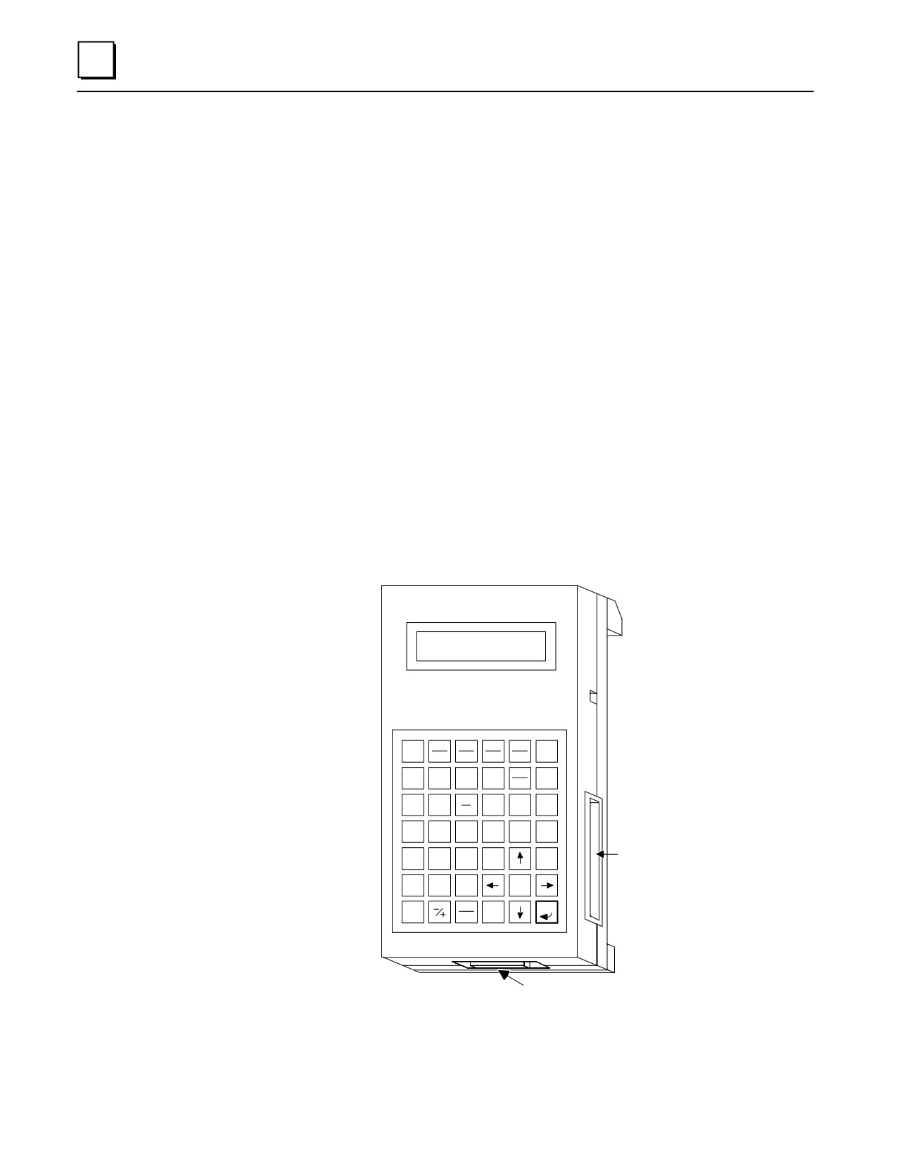
Some models of the Series 90-30 PLC can be programmed with the GE Fanuc Hand-Held
Programmer (HHP). The HHP uses the Statement List Language. With the HHP, you
can develop, debug, and monitor logic programs, monitor data tables, and configure
PLC and I/O parameters.
Note
The user logic program in Series 90-30 CPU numbers 350 and above
cannot be viewed or edited with the Hand-Held Programmer. You must
use Logicmaster 90-30, Control, or VersaPro programming software with
those CPUs.
The HHP connects to the CPU serial port through a 15-pin D-type connector on the
Series 90-30 PLC power supply in the CPU baseplate. The physical connection is
through a 6-foot (2-meters) long cable (IC693CBL303). This cable also provides power
connections to the HHP, and provides a signal that tells the PLC that an HHP is attached.
The HHP can be connected or disconnected while the PLC is powered-up. The HHP
does not require communications parameter configuration in order to communicate
with a PLC. This makes it useful for troubleshooting a communications problem
between a PC and the PLC.
a43052
GE Fanuc
SERIES 90-30
PROGRAMMABLE
CONTROLLER
HAND HELD PROGRAMMER
OUT
SETM
RSTM
TMR
LD
MODE
OUTM
SET
RST
ONDTR
D
E
F
UPCTR
AND
OR
NOT
BLK
DNCTR
RUN
A
I
B
Q
CM
G
FUNC
DEL
A I
AQ
T
S
7
8
9
R
#
SRCH
SLOT
4
5
6
WRITE
INS
FOR
MEMORY
READ
CARD
1
2
3
VRFY
HEX
ENT
0
CLR
DEC
SERIAL PORT CONNECTOR
TO CPU SERIAL PORT
Figure 11-5. Hand-Held Programmer for the Series 90-30 PLC
11-6
Series 90-30 PLC Installation and Hardware Manual - October 1999
GFK-0356P
11
HHP Features
The keypad for the HHP is a sealed type with tactile feedback, and has 42 keys, arranged
in a matrix of six keys across by seven keys down. It has a two-line by 16 character LCD
display screen.
HHP Memory Card (IC693ACC303)
The HHP has a slot for a removable memory card , which provides a means for
non-volatile, off-line program storage and restoration. The memory card can only be
used with CPU numbers 311 through 341. CPU numbers 350 and above do not support
either the HHP or the memory card. The memory card plugs into a connector accessed
through a slot on the lower right side of the HHP (see previous figure).
HHP Modes of Operation
The HHP functionality is basically divided into four modes of operation which are
selected through a key sequence on the keypad. These modes are: program mode,
protection mode, data mode, and configuration mode.
Program Mode:
Allows you to create, change, monitor, and debug Statement List logic. This
mode also allows read, write, and verify functions with the memory card,
EEPROM, or flash memory.
ProtectionMode
Provides a way to control access to (protection of) certain PLC functions,
including program logic, reference data, and configuration information. The
use of this function is optional; however, it is convenient in that it allows you to
protect parts of the PLC system from accidental or deliberate modification.
Protection is provided through four levels of passwords assigned by the user.
DataMode
Allows you to view, and optionally alter values in various reference tables.
Several display formats can be selected in which to view this data: binary,
hexadecimal, signed decimal, and timer/counter.
ConfigurationMode
Allows you to define the types of I/O modules that are installed or will be
installed in the PLC system. You can also assign I/O module addresses to these
modules. This feature is convenient in that it allows you to write and test logic
programs using discrete references assigned to I/O modules that are not yet
installed. In this mode, you can also configure CPU data, such as real-time
clock , coil check, and HHP characteristics, such as keyclick on or off.
Documentation
For detailed information about the Hand-Held Programmer, refer to GFK-0402,
the Series 90-30/20/Micro Hand-Held Programmer User’s Manual.
GFK-0356P
Chapter 11 Programmer Hardware Products
11-7
11
IC693PIF301/400
Personal Computer Interface (PCIF) Cards
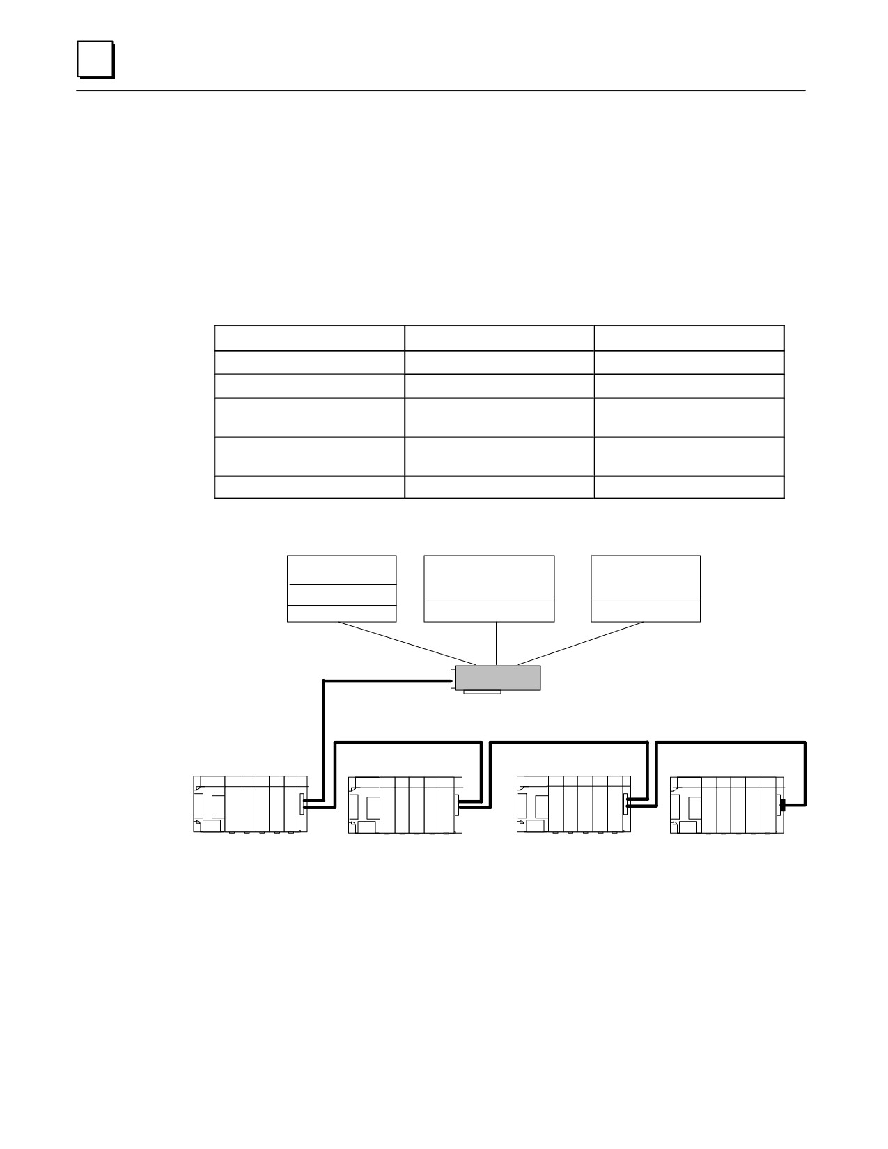
These two Personal Computer Interface cards (PCIF and PCIF2) provide an alternative
method of controlling Series 90-30 I/O. Either card can be used in place of a Series 90-30
PLC CPU. These ISA-compatible cards can be installed in any IBM-PC/AT ISA bus
computer. The cards are implemented using computer language software (for example, C),
or PC control software, such as Total Control Products’ FrameworX Automation Software.
Table 11-1. Personal Computer Interface Card Comparison Table
ITEM
PCIF
PCIF2
Catalog Number
IC693PIF301
IC693PIF400
Amount of I/O controlled
1,280 bytes
25,886 bytes
Number of Series 90-30
Up to four Expansion or
Up to seven Expansion or
racks controlled
Remote racks
Remote racks
Slot requirement
IBM-PC/AT ISA, 8-bit, half
IBM-PC/AT ISA, 16-bit, full
size
size
Documentation
GFK-0889 (IPI)
GFK-1540 (data sheet)
47016
DOS-BASED
MICROSOFT C/TURBO C
WINDOWS-BASED
SOFTWARE
PROGRAMS
SOFTWARE
C LIBRARY
WINDOWS DLL
DOS TSR ROUTINE
OR
OR
MS-DOS
MS WINDOWS
MS-DOS
I/O EXPANSION CABLE
PCIF or PCIF2
I/O EXPANSION CABLE
I/O EXPANSION CABLE
I/O EXPANSION CABLE
SERIES 90-30 I/O
SERIES 90-30 I/O
SERIES 90-30 I/O
SERIES 90-30 I/O
ÎÎÎÎÎÎ
ÎÎÎÎÎÎ
ÎÎÎÎÎÎ
Î
ÎÎÎÎ
ÎÎÎÎÎ
ÎÎÎÎÎ
ÎÎÎÎÎ
ÎÎÎÎÎ
ÎÎÎÎÎÎ
ÎÎÎÎÎÎ
ÎÎÎÎÎÎ
ÎÎÎÎÎÎ
5 OR 10 SLOT
5 OR 10 SLOT
5 OR 10 SLOT
5 OR 10 SLOT
BASEPLATE
BASEPLATE
BASEPLATE
BASEPLATE
Figure 11-6. Example of PCIF Interface to Series 90-30 I/O
Both of these PCIF cards have a 25-pin I/O expansion connector that connects to standard
Series 90-30 Expansion and Remote baseplates (see the “Baseplates” chapter) via I/O
expansion cabling. Remote racks can be located up to 700 feet ( 213 meters) and Expansion
racks up to 50 feet (15 meters) from the personal computer. Several standard prewired I/O
expansion cables are available from GE Fanuc. Alternately, custom length cables can be
built. Please refer to the “Cables” chapter of this manual for information on standard and
custom I/O expansion cables.
11-8
Series 90-30 PLC Installation and Hardware Manual - October 1999
GFK-0356P
11
These cards also provide connections to an internal watchdog-supervised RUN output relay
contact. This contact is closed under normal operating conditions, but opens if the
computer or software application fails, which makes it useful for interfacing with external
safety circuits.
These cards support all Series 90-30 discrete and analog I/O modules (except 16-channel
analog modules). A variety of smart modules from Horner Electric, Inc. are also
supported.
A C Language Interface software product, available from Horner Electric, works with both
Borland Turbo C and Microsoft C. The source code for this interface is available from
Horner Electric (catalog number HE693SRC844).
Documentation
Documentation for these cards is noted in the table above. Additional user ’s
documentation is available from Horner Electric, Inc.
GFK-0356P
Chapter 11 Programmer Hardware Products
11-9
11
IC655CCM590 Isolated Repeater/Conver ter
This item is no longer available. The information provided in this manual is for the
convenience of those still using this product. This product also went by an earlier
catalog number, IC630CCM390, and is nicknamed, the “Brick.” Details can be found in
Appendix E.
Note
In most applications, the newer IC690ACC903 Port Isolator can be used
in place of the IC655CCM590 Isolated Repeater/Converter.
IC690ACC903 Port Isolator
This product was produced to fill the need created when the IC655CCM590 Isolated
Repeater/Converter became obsolete. It provides 500 volts of isolation between
connected RS-485 ports. It can be used in either single or multi-drop applications, and
has a cable length working distance of 4,000 feet (1,219 meters). It is physically smaller
than the IC655CCM590. For details about this product, please refer to Appendix G.
11-10
Series 90-30 PLC Installation and Hardware Manual - October 1999
GFK-0356P
Chapter
System Design
12
Introduction
This chapter does not pretend to cover every possible aspect of designing a Series 90-30
system, but it does provide you with basic product selection guidelines and with help in
finding the information you need. You will also find the GE Fanuc Automation Solutions
Catalog to be a valuable tool for system design.
Step 1: Planning Your System
Planning is an important part of designing a system. The better you plan the system, the
less trouble you will have installing and implementing it. The following list discusses
some basic things to know or have when planning your system:
Expectations. If a new system, what is it expected to do? If retrofitting an existing
system, what does it do now, and what is it expected to do after it is retrofitted.
Specifications (preferably in writing). These include such things as operating
environment information, speed, accuracy, repeatability, size, conformance to
standards, cost restrictions, time requirements, etc.
Technical documentation. If retrofitting existing equipment, you can refer to its
documentation (layout drawings, schematics, etc.). If the documentation is lost,
perhaps a copy is available from the manufacturer. Additional information may be
gathered from discussions with the equipment operators and maintenance
technicians. For a new design, there are probably mechanical or process drawings of
the equipment.
Step 2: Determining I/O Requirements
This step comes next because other Series 90-30 component choices are dependent on
the number of I/O points required. In particular, the number of modules required, and
their locations, determines what type and how many baseplates are needed and also is a
major factor in CPU selection. Note that there are some restrictions on the maximum
number of certain types of modules (Analog I/O and Option) that can be supported in
one PLC system. See the table “Maximum Number of Modules Per System” for data.
To start, determine how many I/O points, both analog and discrete, are needed for
your system. If retrofitting an existing system, use the schematic diagrams for the
system. If designing a new system, use the mechanical drawings or specifications to
determine what inputs and outputs are needed. List these on a piece of paper (or on
12-1
GFK-0356P
12
your drawing software screen). Separate them into four type, to correspond to the
four types of modules you will use: Discrete Input, Discrete Output, Analog Input,
Analog Output. If there are any special requirements, such as fast response, etc.,
make a note of them on the page. Also, if parts of your system are physically
separated from other parts, meaning you will probably be using Expansion or
Remote Racks, create a separate list for each location.
When you have finished developing your I/O lists, determine how many I/O
modules of each type you need. Although there is an abbreviated ”I/O Modules”
chapter in this manual, you should refer to publication GFK-0898, Series 90-30 PLC
I/O Module Specifications User’s Manual for complete details. If you are using Remote
Racks, create a separate list for each location.
Additional I/O Module Selection Factors
Voltage/Current Requirements - A wide variety of possible operating voltage and
current requirements can be met with Series 90-30 I/O modules.
Positive or Negative Logic - The applicable type can be selected to match sink or
source signal requirements. See GFK-0898, Series 90-30 PLC I/O Module Specifications
User’s Manual, for details.
Isolation Requirements - Isolated discrete I/O and relay output modules may be
selected to meet isolation requirements.
Hard Contact Requirements - Relay output modules can be applied.
Cost - The selection of certain modules can possibly reduce the number of racks
required in your system. For example, 32-point discrete I/O modules can save rack
space compared to lower density modules.
Standardization - Sometimes a company will standardize on particular types of
modules to simplify training or stocking of spare parts.
Response Time and Noise immunity - I/O modules have different response time
and noise immunity capabilities. These factors should be considered when selecting
I/O modules. In general, higher response speed is usually attained at the sacrifice of
some noise immunity. Therefore, if high response speed is not a requirement, it
would be better to select a slower I/O module that has higher noise immunity.
However, all I/O modules, regardless of their response time rating, have a
reasonable level of noise immunity. Note that the IC693APU305 I/O Processor
Option module, with its 500 us update time, can handle I/O signals that are too fast
for the CPU to handle directly (see GFK-1028, Series 90-30 I/O Processor Module User’s
Manual).
Step 3: Selecting Option Modules
There are several application requirements that determine Option module selection.
However, note that there are some restrictions on the maximum number of certain types
of modules (Analog and Option) that can be supported in one PLC system. See the table
“Maximum Number of Modules Per System” for data.
Interfacing with a Particular Protocol or Standard - CCM, Ethernet, FIP, Genius,
RTU, SNP, etc.
Interfacing with GE Fanuc CNC controls- Use the IC693BEM320 and
IC693BEM321 I/O Link modules.
12-2
Series 90-30 PLC Installation and Hardware Manual-October 1999
GFK-0356P
12
Distance - Genius controller modules can communicate at distances up to 7,500
feet (2,286 meters). Serial communications using the RS-485 standard can cover up
to 4,000 feet (1,219 meters). FIP networks are rated for 1,640 feet (500 meters).
Modules with serial ports communicating via modems and telephone lines or
satellite links can cover unlimited distances.
High speed inputs - The IC693APU300 High Speed Counter can be used with
encoders to count high speed pulse trains. The IC693APU305 I/O Processor module
is an intelligent module that can satisfy high speed input and output requirements
independent of the PLC scan.
Motion needs - The IC693APM301/302 and IC693DSM302 (and the future
IC693DSM314) are motion control modules that work with servo motor controllers
and other motion devices. The IC693APU300 High Speed Counter module can count
high speed pulses from encoders for use in measuring motion-related data.
Temperature control - The IC693TCM302 Temperature Control Module (TCM) has
thermocouple inputs and PWM outputs.
Extended features - Where there are two or more Option module choices for a
particular application, often an extended feature requirement determines which one
to choose. For example, there are two Ethernet choices, the IC693CMM321 and the
IC693CPU364, but only the IC693CPU364 has Ethernet Global Data (EGD) capability.
Another example: There are three Genius controller modules, the IC693CMM301
Genius Communications Module (GCM), the IC693CMM302 Enhanced Genius
Communications Module (GCM+), and the IC693BEM331 Genius Bus Controller
module (GBC). While all three are capable of basic Genius communications, only
the Genius Bus Controller module can control Genius Blocks.
Remote or distributed I/O needs - One distributed I/O solution is the use of GE
Fanuc’s Genius Blocks, which can be mounted at the point of use and connected
with a PLC’s Genius Bus Controller (GBC) module via a twisted-pair cable. The
Genius Bus Controller is the only Series 90-30 module that can control Genius
Blocks. Other modules (GCM, GCM+) can read input data broadcast by Genius
Blocks, but cannot send commands to them. By selecting the applicable bus
interface unit (BIU), you can use GE Fanuc Field Control distributed I/O to interface
to Series 90-30 WorldFIP, Profibus, and Genius buses.
State Logic - These products allow “Natural Language programming” as an
alternative to ladder logic. This makes program creation, documenting, and editing
easier for those not trained in ladder logic programming. Industries that are
required by law to thoroughly document any changes to their system find State
Logic to be especially useful.
Cost - Sometimes an Option module choice can be made based on the basis of cost.
This is the case where either of two modules are capable of filling a need. For
example, if you only need the capabilities of the IC693CMM302 Enhanced Genius
Communications Module (GCM), you wouldn’t have to purchase the more capable,
but more expensive, IC693BEM331 Genius Bus Controller module (GBC).
Performance - Higher data transfer rate or amount of data often dictates which
Option module will be used. For example, the IC693CMM302 Enhanced Genius
Communications Module can transmit and receive many times more data than the
IC693CMM301 Genius Communications Module, and it transfers data to the PLC
CPU at a faster rate. A comparison table for these two modules is found in
Appendix A of GFK-0695.
GFK-0356P
Chapter 12 System Design
12-3
12
Standardization - Sometimes a company will standardize on particular types of
modules to simplify training or stocking of spare parts.
Display requirements - Several options are available for interfacing with GE Fanuc
Human to Machine Interface (HMI) devices.
Third-party solutions - Many automation solutions result from combining GE
Fanuc product with third-party products. There are dozens of third-party modules
and other products that work with GE Fanuc PLC products. Example s of
third-party Series 90-30 modules are Profibus, DeviceNet, SDS, LonWorks,
Interbus-S, RTU/Modbus,ASCII Basic,RTD, and Millivolt/Strain Gauge Input.
Contact your GE Fanuc distributor for further information, or check the GE Fanuc
Web site for third-party product information and links.
Step 4: Selecting a CPU
Once you have determined how many and what type of I/O and Option modules you
require, you can select a CPU. Many of the factors that apply to selecting Option
modules, such as performance, cost, standardization, etc. also apply to selecting a CPU.
Details on CPU capabilities are found in the “CPUs” chapter.
Number of modules required by the system - Embedded CPUs come in 5-slot or
10-slot sizes and they do not support Extension or Remote baseplates. Therefore, if
a system requires only a few modules, these may be an option. If more than 10
modules are required, you must select a Modular CPU. The CPU331-341 CPUs
support up to 5 total baseplates, and the CPU350-364 CPUs support up to 8 total
baseplates. If you need more than 49 total Option and I/O modules, you will need
to use one of the CPU350-364 group of CPUs.
Modules with Quantity Restrictions- Many modules are restricted as to how many
may be used in one system. This number also varies by CPU. For example, in the
case of an 8-channel Analog Output module, the maximum number per system is:
4 if using a 311, 313, or 323 CPU
8 if using a 331, 340,or 341 CPU
79 if using a 360-364 CPU
Please see the section “Maximum Number of Modules Per System” table for data.
Types of Option Modules - The PCM, ADC, CMM, and SLP modules can only work
in a Modular CPU baseplate. Use of these modules would, therefore, rule out the
use of Embedded CPUs (311, 313, 323). See the section “Location of Modules in the
PLC Racks” for more information.
Performance - as shown in the “CPUs” chapter, the CPU350 - 364 CPUs use a more
powerful microprocessor than the lower numbered CPUs. For applications where
higher performance is required, one of these would be a good choice. For
math-intensive applications, the CPU352, with its built-in math coprocessor, would
give the best performance. For Ethernet applications, the CPU364 with its built-in
Ethernet interface, provides faster performance than separate CPU and Ethernet
modules because they have to communicate over the PLC backplane, which is
slower than the CPU364’s internal path. For serial communications, the CPUs 351,
352, and 363 (using Ports 1 and 2) perform faster than an IC693CMM311 module.
Extended features - The IC693CPU364 has a built-in Ethernet interface which
would eliminate the need for a separate Ethernet module. This would save a PLC
12-4
Series 90-30 PLC Installation and Hardware Manual-October 1999
GFK-0356P
12
slot. The CPU351, CPU352, and CPU353 each have two additional built-in serial
ports which eliminate the need for a separate serial communications Option module.
The CPUs 350-364 have extra features and capabilities that the other CPUs do not
have such as, Floating Point Math, Sequential Event Recorder, and Memory Protect
Key Switch. Also, CPUs 351-364 have larger total memory size, as well as
configurable analog and register memory.
Memory requirements - The CPU351-364 CPUs have configurable analog and
register memory. This makes them more capable of meeting the needs of (1) Option
modules that require this type of memory and (2) user programs that require larger
amounts of register or analog memory. The CPU360 does not have configurable
memory and has a lower base memory size than the CPU351-364 CPUs. The
CPU360-364 CPUs have standard Flash PROM for user data storage. This is not
available in some of the other CPUs. See the “CPU Firmware and PROM
Configurations” table in the “CPUs” chapter for details.
Expandability and Upgradeability - The Embedded CPUs do not support
Expansion or Remote racks and do not allow changing CPU type. Therefore, they
have limited expandability or upgradeability options. Modular CPUs can be
upgraded to more powerful CPUs. The type of modular CPU determines whether a
system can have a total of 5 or 8 baseplates, which can have a direct bearing on the
future expansion capabilities of a system. For example, if you only need 49 total
Option and I/O Modules, you could use one of the CPU331-341 CPUs. However,
you would be at the maximum module limit and would not be able to add any more
to the system without changing the CPU. If you used, instead, one of the
CPU360-364 CPUs, you could later add up to 30 more modules while keeping the
same CPU. This would simplify expanding the system.
Cost - If some of the other factors such as performance or extended features are
not major issues, one of the lower cost CPUs can be applied. However, sometimes
purchasing a more expensive CPU with extended features can be less costly than
purchasing a lower cost CPU and an additional Option module to cover the feature
needed. Besides the direct cost of the modules, using the single CPU would save a
PLC slot, which could help eliminate the need for, and cost of, an extra Baseplate,
Power Supply, I/O Bus Expansion Cable, etc. Since prices are subject to change, it
would not be practical to give an example of this. Please check with your distributor
for current pricing information.
Display requirements - The CPU351, CPU352, CPU363, and CMM311 have serial
ports that are often used to communicate with Human to Machine Interface (HMI)
or Operator Interface (OI) devices.
Time of day (TOD) clock requirements - The Embedded CPUs do not have one,
the Modular CPUs do.
System size limitation - If you are close to the maximum number of modules
limitation of your system, you can use modules that have dual functions to conserve
rack slots. For example, the CPU364 has CPU and Ethernet communications
capability in one module. The CPUs 351, 352, and 363 have CPU and Serial
Communications capability in one module. There are discrete and analog
combination I/O modules that provide a limited number of both inputs and outputs
in one module. Also, the 32-point discrete I/O modules conserve rack slots
compared with lower density (16-point and less) I/O modules. You may also be able
to use Genius Blocks or Field Control distributed I/O to accommodate the need for
additionalI/O, since these do not require a PLC slot; they communicate with the
GFK-0356P
Chapter 12 System Design
12-5
12
PLC over a communications bus. Genius Blocks communicate over a Genius Bus,
and Field Control can communicate over Genius, FIP, or Profibus busses.
Protection against unauthorized changes. CPUs 360 - 364 have a keylock switch
that can be locked to protect against unauthorized changes to the PLC. CPUs 311 -
341 do not have a keylock switch. However, all CPUs have the capability of
password protection for the application program.
Step 5: Selecting Baseplates
The requirements determined in the previous steps will largely dictate what baseplates
to select. Please refer to the “Baseplates” chapter for additional details.
Embedded CPU baseplate - If the previous selections dictate the use of an
Embedded CPU, you have three choices. The CPU311 and CPU313 are 5-slot sizes,
and the CPU323 is a 10-slot size. The CPU311 has 6K Bytes of memory and the
CPU313 has 12K Bytes.
Modular CPU Baseplate - If you need a modular CPU, you must use a Modular
CPU baseplate. There can be only one CPU baseplate per system. There are just
two types, 5-slot and 10-slot. If you only need a 5-slot size, you may want to
consider whether the extra slots that a 10-slot size would provide would be
advantageous for possible future expansion. On the other hand, the 5-slot size
requires less space.
Expansion and Remote baseplates - These also come in 5-slot and 10-slot sizes. In
general, it is best to use Expansion baseplates where possible instead of Remote
baseplates because of the better speed performance of the Expansion baseplates.
Where a total cable distance of over 50 feet is required, Remote baseplates must be
used. In cases where you only need a 5-slot size, you may want to consider whether
it would be advantageous to use a 10-slot size in order to have open slots for future
expansion. That factor should be weighed against the fact that the 5-slot size
requires less space and costs less.
Physical size - For locations with size limitations, one or more 5-slot baseplates may
be a good choice. See the “Baseplates” chapter for baseplate dimensions and
clearance requirements.
Number of Modules Required - The number of modules need at each location will
have a bearing on the sizes of racks required. You may choose to use a smaller rack
(5-slot), if possible, to save cost and space. However, as noted below, a larger rack
(10-slot) with unused slots will leave some room for future expansion, if desired.
Expandability - For future expansion, you might wish to leave some unused slots in
certain baseplates.
Step 6: Selecting Power Supplies
The following factors will affect your Power Supply selection decisions. See the “Power
Supplies” chapter for additional details.
Power capacity - All Series 90-30 Power Supplies have three individual outputs:
+5VDC, +24VDC (Relay), and +24VDC (Isolated). Although all of these Power
Supplies are rated at 30 Watts maximum total output, the rating of the +5VDC
output varies from supply to supply, as shown in the following table. For
applications requiring heavy loading of the +5VDC supply, choose one of the “High
Output” power supplies: IC693PWR330 or IC693PWR331.
12-6
Series 90-30 PLC Installation and Hardware Manual-October 1999
GFK-0356P

12
Input voltage - As seen in the next table, nominal input voltage choices are 24VDC,
48VDC, 120VAC, 125VDC, and 240VAC.
Table 12-1. Power Supply Feature Comparison Table
Catalog
Load
Nominal
Number
Capacity
Input
Output Capacities (Voltage/Power
)
IC693PWR321
30 Watts
100 to 240 VAC or
+5 VDC
+24 VDC Isolated
+24 VDC Relay
125 VDC
15 watts
20 watts
15 watts
IC693PWR330
30 Watts
100 to 240 VAC or
+5 VDC
+24 VDC Isolated
+24 VDC Relay
125 VDC
30 watts
20 watts
15 watts
IC693PWR322
30 Watts
24 or 48 VDC
+5 VDC
+24 VDC Isolated
+24 VDC Relay
15 watts
20 watts
15 watts
IC693PWR331
30 Watts
24 VDC
+5 VDC
+24 VDC Isolated
+24 VDC Relay
30 watts
20 watts
15 watts
Total of all outputs combined cannot exceed 30 watts.
Reducing PLC Module Count by Using Other GE Fanuc Products
If system size limitations (more than 79 modules are needed) are a problem in a system
using Remote racks, a possible solution could be the use of GE Fanuc Genius Blocks,
Field Control, or VersaMax products. These distributed I/O devices can be used instead
of Remote racks in remote locations in some cases, and their use would not add to the
Series 90-30 module count.
Genius Blocks
These are intelligent distributed I/O blocks that are panel-mounted at the point of use.
They communicate with a Genius Bus Controller (GBC) module in the PLC via a
shielded, twisted-pair cable. They are not included in the PLC module count, but do
require I/O memory allocation. A single GBC module in a PLC rack can control up to 31
Genius Blocks. Genius Blocks come in discrete and analog I/O, high speed counter, RTD,
and thermocouple interface types. For more information on using Genius Blocks, see
GEK-90486-1, Genius I/O System and Communications User’s Manual, and GEK-90486-2,
Genius I/O Discrete and Analog Blocks User’s Manual.
Field Control
These are intelligent distributed I/O units that mount at the point-of-use on a 35mm x
7.5mm DIN-rail. They can communicate over Genius, FIP, or Profibus buses. They are
not included in the PLC module count, but do require I/O memory allocation. A Field
Control unit consists of a Bus Interface Unit (BIU) that interfaces to the applicable bus,
from one to eight I/O modules, and cabling. I/O modules come in various discrete,
analog, and RTD types. A local logic processor module (MFP) is also available. For
further information on Field Control, see the following:
GFK-0826, Field Control Distributed I/O and Control System I/O Modules User’s Manual
GFK-0825, Field Control Genius Bus Interface Unit User’s Manual
GFK-1175, Field Control FIP Bus Interface Unit User’s Manual
GFK-1291, Field Control Profibus Bus Interface Unit User’s Manual
GFK-0356P
Chapter 12 System Design
12-7
12
VersaMax
VersaMax I/O modules can be used as distributed I/O, communicating with a Series
90-30 PLC over one of three bus types: Genius, Profibus, or Device Net. This
arrangement would require an Option module for the desired bus type in the Series
90-30 PLC as well as the applicable Network Interface Module in the VersaMax system.
For more information on the VersaMax products, please see GFK-1504, VersaMax Modules,
Power Supplies, and Carriers Manual.
Designing For Safety
A good design should not only function properly and efficiently, but must also protect
personnel and equipment from harm. Although some basic guidelines are found in the
“Installation” chapter of this manual, it is not possible to cover every aspect of safety
because of the diversity of applications. Additionally, it is not practical for this manual to
try to cover all the possible codes and regulations that may apply to your locality or type
of equipment. You have the ultimate responsibility to consult applicable safety codes
for your locality, or that pertain to the particular type of equipment you are designing,
and ensure that your design complies with these standards. In the United States, the
National Electric Code (NEC) has been adopted by many localities. The United States
Occupational Safety and Health Administration (OSHA) regulations also contain many
safety regulations that apply to all industrial equipment in the United States. In the
absence of local regulations, the NEC and OSHA regulations should be followed when
designing your system, in addition to the information contained in this manual. OSHA
regulations can be accessed on-line at www.osha.gov. Some key safety issues are
outlined below:
Protection From Electrical Shock
Proper wiring design, including grounding and circuit protection issues, should be
followed. Personnel should be prevented from accidentally coming in contact with
hazardous voltages. Also, unauthorized personnel should be prevented from gaining
access to high voltage cabinets and panels. Interlock circuits are often used for this
purpose.
Fire Prevention
The guidelines in the NEC and OSHA regulations protect against fires, especially those
caused by faulty electrical design.
Protection From Mechanical Hazards
Personnel should be protected from physical hazards, such as moving mechanisms like
conveyors or index tables or mechanical pinch points. The use of interlocked safety
gates, light curtains, safety mat switches, dual hand buttons, physical barriers (guards),
etc. can be used for this purpose. See the applicable section of the OSHA regulations for
details.
Protection From Electrical Failure
In the event of a system component failure, the design should be an acceptable
“fail-safe” one in which the failure does not cause a safety hazard such as a runaway
12-8
Series 90-30 PLC Installation and Hardware Manual-October 1999
GFK-0356P
12
condition or a disabling of emergency stop circuits. Emergency stop and other safety
circuits should consist of hard-wired components that tend to fail in a harmless manner.
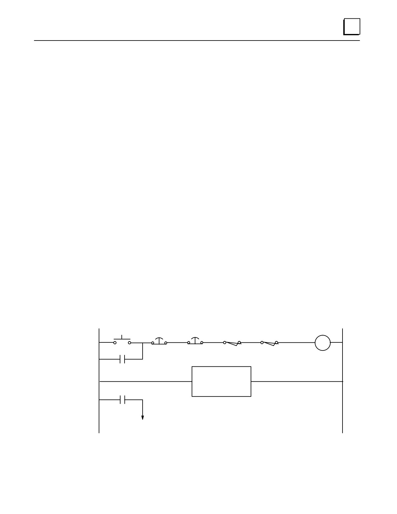
For example, in a Master Control Relay (MCR) circuit, use series-wired, normally closed
Emergency Stop pushbutton switches and interlocks to control an electro-mechanical
Master Control Relay (see next figure). This relay should directly disable motor starters,
PLC output circuits, etc. This type of circuit tends to fail “open,” which disables the
equipment. For example, if a wire breaks or a contact wears out, the circuit opens and
the MCR drops out. If solid state devices fail, they tend to fail “shorted,” which in the
case of PLC output circuits would cause the controlled device to turn on or stay on.
In the circuit below, the MCR is an electro-mechanical relay. It is energized by the
application of power to its solenoid coil which magnetically pulls the contacts to their
energized states. When de-energized, the contacts move to their normal, at rest states
by the pull of a mechanical spring. When the Reset pushbutton is pressed, and if all four
of the E-Stop and Gate switches are closed, the MCR relay will energize and “latch” in
the energized state through its MCR contact in parallel with the Reset pushbutton. Its
other MCR contact applies power to the motor starter and PLC output circuits. If any
one of the E-Stop or Gate switches opens, or if a wire breaks in this circuit, or if the MCR
coil becomes defective, MCR will de-energize and open the circuit to the motor starters
and PLC output circuits.
As shown, the PLC’s main power and input circuits are not controlled by the MCR since
they do not directly control any outputs. Keeping these circuits energized is desirable
because this allows the PLC to continue gathering data, recording fault information, and
controlling communications, even if its Output module outputs are disabled by the
MCR.
If an additional margin of safety were desired, two MCR relays could be used. Their
coils would be wired in parallel, their normally open contacts wired in series, and their
normally closed contacts wired in parallel. This would help guard against the possibility
of a “welded contact” on a single MCR relay.
Master Control
Reset
E-Stop 1
E-Stop 2
Gate 1
Gate 2
Relay (MCR)
MCR
MCR
PLC Main Power and
Input Power Circuits
MCR
To Motor Starters, PLC
Output Module Circuits, etc.
Figure 12-1. Hard-Wired MCR Circuit Example
GFK-0356P
Chapter 12 System Design
12-9
12
Protection From Design Changes or Overrides
Only authorized personnel should be allowed to make changes that could impact the
safe operation of the equipment. Passwords and lockout circuits may be used to
accomplish this. Some Series 90-30 CPUs have keylock switches to protect against
program changes (see “CPUs” chapter for keylock switch details).
Safety Documentation
PLC Program Documentation. Thorough documentation will help you and others
who work on the equipment remember and understand how the safety circuits and
features work. (In some industries, applicable regulations may require this type of
documentation.) The PLC programming software gives you extensive
documentation abilities.
For example, you can create Nicknames such as “PSTOP,” Descriptions such as
“Program Stop Coil,” and Comments such as “This coil is used to stop the program
cycle, but it does not turn off power to the main hydraulic circuit. However, if the
operator opens the safety gate, the Safety Gate Interlock switch will open and shut
off the hydraulic pump.” These Nicknames, Descriptions, and Comments become
part of the PLC program and can be viewed with the applicable software.
As an alternative to ladder logic programming, the State Logic programming
language makes it easier to document PLC program design because it uses “Natural
Language” expressions instead of ladder logic symbols.
Electrical and mechanical prints should contain notations pertaining to safety
issues.
Written operating and maintenance instructions as well as training should be
provided to operators and maintenance personnel. These should address any
applicable safety issues.
Guarding Against Unauthorized Operation
Keylock switches and passwords are frequently used for this purpose.
Labeling, Guarding, and Lighting Issues
Labeling. Operator devices such as pushbuttons, switches, or on-screen (software)
buttons should be clearly labeled as to their function.
Guarding. Operator devices should be guarded, where applicable, to prevent them
from being activated accidentally. Recessed pushbutton designs or pushbuttons
with surrounding guard rings might help prevent the pushbutton from being
depressed if, for example, a tool were dropped or laid upon it. Mounting
pushbutton stations to vertical surfaces also may help avoid this problem.
Lighting. Illumination levels in the working area should be adequate so that all
labels can be clearly seen.
Equipment Accessibility Issues
The equipment should be laid out so as to give operators sufficient room to perform
their tasks safely. Also, sufficient clearance should be provided so that maintenance
personnel have safe access to electrical panels, control boxes, etc. These minimum
clearances are specified in the NEC and OSHA requirements.
12-10
Series 90-30 PLC Installation and Hardware Manual-October 1999
GFK-0356P

12
Number of Modules Per Series 90-30 PLC System
The following table lists the maximum number of each type of I/O and option modules
that can be installed in a Series 90-30 PLC system. The number of modules that can be
installed in a system depends on several factors, including available references for each
CPU model, the current rating for each module to be installed in the system, and other
installed modules. Before installing modules in a baseplate, verify that the total current
rating of all of those modules does not exceed the power rating of the power supply.
Table 12-2. Maximum Number of Modules Per System
CPU
CPU
CPU
Module Type
Model 311/313/323
Model 331/340/341
Model 350 - 364
Input and Output, Discrete
5 (5-slot baseplate)
(331/340/341)
79
10 (10-slot baseplate)
Input Module, Analog , 4-Channel
5 (5-slot baseplate)
40
64
8 (10-slot baseplate)
Input Module, Analog, 16-Channel
4
8 (Model 331)
51
12(Model340/341)
Output Module (Voltage), Analog, 2-Channel
5 (5-slot baseplate)
16 (Model 331)
48
6 (10-slot baseplate)
30(Model340/341)
Output Module (Current), Analog, 2-Channel
3 (5-slot baseplate)
15 (Model 331)
24
3 (10-slot baseplate)
15(Model340/341)
Output Module, Analog, 8-Channel
4
8 (Model 331)
79
32(Model340/341)
Combination Input/Output Module, Analog
5 (5-slot baseplate)
21 (Mode3 31/40/341)
79
4-ChIn/2-Ch Out
10 (10-slot baseplate)
Programmable CoprocessorModule
n/a
4
4
Alphanumeric Display CoprocessorModule
n/a
4
4
Communications Control Module
n/a
9
9
State Logic ProcessorModule
n/a
Refer to the State Logic User’s Guide, GFK-0726.
Genius Communications ModulE (1)
1
1
1
Enhanced Genius Communications ModulE (1)
2
2
2
High Speed Counter
4 (5/10-slot baseplate)
8 (Model 331)
79
32(Model340/341)
I/O Link Interface Module
5(5/10-slotbaseplate)
49
79
I/O ProcessorModule
2 (5-slot baseplate)
8 (Model 331)
64
4 (10-slot baseplate)
16(Model340/341)
Genius Bus Controller (2)
8
8
8
Ethernet Interface Module
Refer to the Series 90-30 TCP/IP Ethernet Communications User’s Manual,
GFK-1084 for details.
Motion Mate APM300 Module
Refer to the Motion Mate APM300 User’s Manuals, GFK-0840 or GFK-0781
for details.
Motion Mate DSM302 Module
Refer to the Motion Mate DSM302 User’s Manual, GFK-1464 , for details.
Motion Mate DSM314 Module
Refer to the Motion Mate DSM314 User’s Manual, GFK-1742 , for details
Temperature Control Module
Refer to the Temperature Control User’s Manual, GFK-1466 for details
Power Transducer Module
Refer to the Power Transducer Module User’s Manual, GFK-1734, for details
(1) The Enhanced Genius Communications Module and the Genius Communications Module cannot be
installed in the same PLC baseplate; however, both modules can be present on the same bus.
(2) Refer to GFK-1034, Series 90-30 Genius Bus Controller User’s Manual fordetails.
GFK-0356P
Chapter 12 System Design
12-11
12
Calculating Power Supply Loading
The load placed on a power supply in a Series 90-30 PLC baseplate is the sum of the
internal and external loads placed on it by all of the hardware components in the
baseplate (backplane, modules, etc.), as well as external loads connected to the Isolated
+ 24 VDC supply. Use of the Isolated +24 Volt power supply output is optional;
however, this output can be used to drive a limited number of input devices. The
maximum total power output rating of the Power Supplies is 30 watts; however, the
individual +5VDC outputs can be rated for either 15 or 30 Watts, depending on the
Power Supply catalog number. See Table 12-1, “Power Supply Feature Comparison
Table,” for details.
Load Requirements for Hardware Components
The following table shows the DC load required by each module and hardware component.
All ratings are in milliamps (except where noted). Input and Output module current
ratings are with all inputs or outputs on. Three voltages are listed in the table:
+5 VDC provides primary power to operate most internal circuits
+ 24 VDC Relay Power provides power for circuits that drive the relays on Relay
modules
+24 VDC Isolated provides power to operate a number of input circuits (input
modules only), and any external circuits connected to the 24 VDC Output terminals
on the power supply terminal strip.
Note that the figures listed in the following table are maximum (worst case)
requirements , not typical requirements.
12-12
Series 90-30 PLC Installation and Hardware Manual-October 1999
GFK-0356P

12
Table 12-3. Load Requirements (in milliamps)
Catalog
+24 VDC
+24 VDC
Number
Description
+5 VDC
Relay Power
Isolated
AD693SLP300
State Logic Processor Module
425
-
-
IC693ACC300
Input Simulator, 8/16 Points
120
-
-
IC693ACC307
Expansion Bus Termination Plug
72
-
-
IC690ACC900
RS-422/RS-485toRS-232Converter
170
-
-
IC690ACC901
RS-422 (SNP) to RS-232, Miniconverter Kit (Version A)
150
-
-
(version B, or later )
100
-
-
IC693ADC311
Alphanumeric Display Coprocessor Module
400
-
-
IC693ALG220
Analog Input, Voltage, 4 Channel
27
-
98
IC693ALG221
Analog Input, Current, 4 Channel
25
-
100
IC693ALG222
Analog Input, Voltage, High Density (16 Channel)
112
41
IC693ALG223
Analog Input, Current, High Density (16 Channel)
120
-
-
IC693ALG390
Analog Output, Voltage, 2 Channel
32
-
120
IC693ALG391
Analog Output, Current, 2 Channel
30
-
215
IC693ALG392
Analog Current/Voltage Output, 8 Channel
110
-
IC693ALG442
Analog Current/Voltage Combination 4 Ch In/2 Ch Out
95
-
129
IC693APU300
High Speed Counter
250
-
-
IC693APU301
Motion Mate APM300, 1-Axis
800
-
-
IC693APU302
Motion Mate APM300, 2-Axis
800
-
-
IC693APU305
I/OProcessor Module
360
-
-
IC693BEM320
I/O Link Interface Module (slave)
205
-
-
IC693BEM321
I/O Link Interface Master Module (w/o optical adapter)
415
-
-
(with Optical Adapter)
615
IC693BEM330
FIP Remote I/O Scanner
609
-
-
IC693BEM331
Genius Bus Controller
300
-
-
IC693BEM340
FIP Bus Controller
(maximum)
1.2A
(typical)
800
IC693CHS391
10-slot Modular CPU Baseplate
250
-
-
IC693CHS392
10-slot Expansion Baseplate
150
-
-
IC693CHS393
10-slot Remote Baseplate
460
-
-
IC693CHS397
5-slot Modular CPU Baseplate
270
-
-
IC693CHS398
5-slot Expansion Baseplate
170
-
-
IC693CHS399
5-slot Remote Baseplate
480
-
-
IC693CMM301
Genius Communications Module
200
-
-
IC693CMM302
Enhanced Genius Communications Module
300
-
-
IC693CMM311
Communications Control Module
400
-
-
IC693CMM321
Ethernet Interface Module
750
-
-
IC693CPU311
Series 90-30 5-Slot Embedded CPU Baseplate
410
-
-
IC693CPU313
Series 90-30 5-Slot Embedded CPU Baseplate
430
-
-
IC693CPU323
Series 90-30 10-Slot Embedded CPU Baseplate
430
-
-
IC693CPU331
CPU (Model 331)
350
-
-
IC693CPU340
CPU (Model 340)
490
-
-
IC693CPU341
CPU (Model 341)
490
-
-
IC693CPU350
CPU (Model 350)
670
IC693CPU351
CPU (Model 351)
890
IC693CPU352
CPU (Model 352)
910
IC693CPU360
CPU (Model 360)
670
IC693CPU363
CPU (Model 363)
890
IC693CPU364
CPU (Model 364)
1.51 A
IC693CSE313
State Logic CPU, 5-slot baseplate
430
-
-
IC693CSE323
State Logic CPU, 10-slot baseplate
430
-
-
GFK-0356P
Chapter 12 System Design
12-13

12
Catalog
+24 VDC
+24 VDC
Number
Description
+5 VDC
Relay Power
Isolated
IC693CSE340
State Logic CPU Module
490
-
-
IC693DSM302/314*
Motion Mate DSM302 or DSM314 Module
1.3A
-
-
IC693MAR590
120 VAC Input, relay Output, 8 In/8 Out
80
70
-
IC693MDL230
120 VAC Isolated, 8 Point Input
60
-
-
IC693MDL231
240 VAC Isolated, 8 Point Input
60
-
-
IC693MDL240
120 VAC, 16 Point Input
90
-
-
IC693MDL241
24 VAC/DC Pos/Neg logic, 16 Point
80
-
125
IC693MDL310
120 VAC, 0.5A, 12 Point Output
210
-
-
IC693MDL330
120/240VAC, 1A, 8 Point Output
160
-
-
IC693MDL340
120 VAC, 0.5A, 16 Point Output
315
-
-
IC693MDL390
120/240VAC Isolated, 2A, 5 Point Output
110
-
-
IC693MDL630
24 VDC Positive Logic, 8 Point Input
2.5
-
60
IC693MDL632
125 VDC Pos/Neg Logic, 8 Point Input
40
-
-
IC693MDL633
24 VDC Negative Logic, 8 Point Input
5
-
60
IC693MDL634
24 VDC Pos/Neg Logic, 8 Point Input
80
-
125
IC693MDL640
24 VDC Positive Logic, 16 Point Input
5
-
120
IC693MDL641
24 VDC Negative Logic, 16 Point Input
5
-
120
IC693MDL643
24 VDC Positive Logic, FAST, 16 Point Input
5
-
120
IC693MDL644
24 VDC Negative Logic, FAST, 16 Point Input
5
-
120
IC693MDL645
24 VDC Pos/Neg Logic, 16 Point Input
80
-
125
IC693MDL646
24 VDC Pos/NegLogic,FAST, 16 Point Input
80
-
125
IC693MDL652
24 VDC Pos/Neg Logic 32 Point Input
5
-
-
IC693MDL653
24 VDC Pos/NegLogic,FAST, 32 Point Input
5
-
-
IC693MDL654
5/12 VDC (TTL) Pos/Neg Logic, 32 Point
195/440
-
-
IC693MDL655
24 VDC Pos/Neg, 32Point Input
195
-
224
IC693MDL730
12/24VDCPositive Logic, 2A, 8 Point Output
55
-
-
IC693MDL731
12/24 VDC Negative Logic, 2A, 8 Point Output
55
-
-
IC693MDL732
12/24VDCPositive Logic, 0.5A, 8 Point Output
50
-
-
IC693MDL733
12/24 VDC Negative Logic, 0.5A, 8 Point Output
50
-
-
IC693MDL734
125 VDC Pos/Neg Logic, 6 Point Output
90
-
-
IC693MDL740
12/24VDCPositive Logic, 0.5A, 16 Point Output
110
-
-
IC693MDL741
12/24 VDC Negative Logic, 0.5A, 16 Point Output
110
-
-
IC693MDL742
12/24VDCPos. Logic ESCP, 1A, 16 Point Output
130
-
-
IC693MDL750
12/24 VDC Negative Logic, 32 Point Output
21
-
-
IC693MDL751
12/24VDCPositive Logic, 32 Point Output
21
-
-
IC693MDL752
5/24 VDC (TTL) Negative Logic, 0.5A, 32 Point
260
-
-
IC693MDL753
12/24VDCPositive Logic, 0.5A, 32 Point Output
260
-
-
IC693MDL930
Relay, N.O., 4A Isolated, 8 Point Output
6
70
-
IC693MDL931
Relay, N.C. and Form C, 8A Isolated, 8 Point Out
6
110
-
IC693MDL940
Relay, N.O., 2A, 16 Point Output
7
135
-
IC693MDR390
24 VDC Input, Relay Output, 8 In/8 Out
80
70
-
IC693PCM300
Programmable Coprocessor Module, 65K
425
-
-
IC693PCM301
Programmable Coprocessor Module, 85K
425
-
-
IC693PCM311
Programmable Coprocessor Module, 380K
400
-
-
IC693PRG300
Hand-Held Programmer
170
-
-
IC693PTM100*
Power Transducer Module
400
IC693TCM302
Temperature Control Module
150
-
-
Refer to module specifications in GFK-0898, Series 90-30 I/O Module Specifications Manual for more details.
Note that the model 350-364 CPUs do not support the A version (IC690ACC901A) of the Miniconverter.
*
Note that this is preliminary information. The IC693DSM314 and IC693PTM100 will not be available until late 1999.
12-14
Series 90-30 PLC Installation and Hardware Manual-October 1999
GFK-0356P

12
Power Supply Loading Calculation Examples
Following are examples of calculations for determining the total load placed on a Series
90-30 PLC power supply by the Series 90-30 PLC hardware. All current figures are
expressed in milliamps. Note that although each output is rated at 15 or 20 watts (with the
exception that the +5 VDC output for the High Capacity power supply is rated at 30 watts),
the total combined output can be no more than 30 watts. The power required by external
circuits connected to the 24 VDC OUTPUT terminals on the power supply terminal strip
should be added to the calculation.
Example 1: Series 90-30, Model 323 Embedded CPU (10-slot baseplate)
Component
+5V
+24V Isolated
+24V Relay
IC693CPU323 Embedded CPU
430
Baseplate
IC693PRG300 Hand-Held Pro-
170
grammer
IC693ALG390 Analog Output
32
120
IC693ALG220 Analog Input
27
98
IC693APU300 HS Counter
190
24 VDC Input (16 points)
5
120
IC693MDL340 Input Module
5
120
IC693MDL740 Output Module
110
IC693MDL240 Input Module
90
IC693MDL310 Output Module
210
IC693MDL940 Relay Out. Mod.
7
135
IC693MDL930 Relay Out. Mod.
6
70
Totals (milliamps)
1281
458
205
(Watts)
6.41
10.99
4.92
Total Watts = 22.32
Example 2: Series 90-30, Model 351 Modular CPU (10-slot baseplate)
Component
+5V
+24V Isolated
+24V Relay
IC693CHS391 Modular CPU
250
Baseplate
IC693CPU351 CPU Module
890
IC690ACC901 Miniconverter Kit
100
IC693PCM301 PCM Module
425
IC693ALG390 Analog Output
32
120
IC693ALG220 Analog Input
27
98
IC693APU300 HS Counter
190
IC693MDL340 Input Module
5
120
IC693MDL740 Output Module
110
IC693MDL240 Input Module
90
IC693MDL310 Output Module
210
IC693MDL940 Relay Out. Mod.
7
135
Totals (milliamps)
2336
338
135
(Watts)
11.68
8.11
3.24
Total Watts = 23.03
GFK-0356P
Chapter 12 System Design
12-15
12
Scan (Sweep) Time Calculation
Scan or Sweep time is the time it takes the PLC CPU to perform all of its tasks one time.
Scan time contribution is the amount of time added to the PLC scan by the software and
hardware components of the system. For systems that may be time-sensitive, this factor
should be made part of the design specification. To help avoid timing issues, the
theoretical scan time should be calculated so that appropriate solutions can be designed
into the system up-front.
Major Design Factors Affecting Scan Time
Size of ladder program
Type of CPU. Some CPUs have faster clock speeds and architecture than others.
Types of instructions used in ladder program
Number of modules
Types of modules. Some modules, such as several of the Option modules, have a
much greater impact than others such as discrete I/O modules.
Location of modules. This refers to the type of rack (CPU, Expansion, or Remote)
that they are installed in.
Connections to other devices such as an HMI, or to other systems via
communications modules or ports.
Cable types. Cable type can have a significant impact on scan time, especially when
connecting Remote racks or communicating over long distances. Propagation time of
data should be minimized to ensure proper system timing and margins. Suggested
cable types for I/O Bus Expansion and communication cables are documented in the
“Cables” chapter. Any deviation in cable types from those recommended may
result in erratic or improper system operation.
Where to Find Scan Time Information
For information on calculating scan time, please refer to the “Sweep Time Calculation”
section of GFK-0467, Series 90-30/20/Micro PLC CPU Instruction Set Reference Manual.
Calculating PLC Heat Dissipation
The amount of heat dissipated by a PLC mounted in an enclosure can be an important
factor in determining the enclosure size needed for the system. This is because the
enclosure must be able to adequately dissipate the heat generated by all of the
components mounted inside so that no components overheat. PLC heat dissipation is
also a factor in determining the need for enclosure cooling options such as fans and air
conditioning. Enclosure manufacturers generally consider enclosure heat dissipation as
a factor in their enclosure selection guidelines. Instructions for calculating Series 90-30
PLC heat dissipation can be found in Appendix H, “Series 90-30 Heat Dissipation.”
12-16
Series 90-30 PLC Installation and Hardware Manual-October 1999
GFK-0356P
12
System Layout Guidelines
Because of the differences from one system to another, it is not practical to try to discuss
every possible layout. Instead, this section offers guidelines and an example to help you
lay out your system.
Benefits of a Good Layout - Safe, Reliable, and Accessible
The layout of your system has a lot to do with how reliably your system will operate,
how easy it will be to install, how well it will look, and how easy and safe it will be to
maintain:
Safety and Maintenance - A good layout helps minimize the chance of electrical
shock to personnel working on the system. It lets maintenance technicians easily
access the unit to make measurements, load software, check indicator lights, remove
and replace modules, etc. It also makes it easier to trace wiring and locate
components while troubleshooting.
Reliability -Proper layout promotes good heat dissipation and helps eliminate
electrical noise from the system. Excess heat and noise are two major causes of
electronic component failure.
Installation Efficiency- A well designed layout allows sufficient room to mount
and wire the unit. This saves time and frustration.
Appearance - A neat and orderly layout gives others a favorable impression of your
system. It lets others know that careful thought went into the design of the system.
PLC Rack Location and Clearance Requirement
The following list provides PLC rack mounting location guidelines. For an example
layout, see the figure “Series 90-30 Example Layout” later in this chapter.
Locate PLC racks away from other components that generate a lot of heat, such as
transformers, power supplies, or power resistors.
Locate PLC racks away from components that generate electrical noise such as
relays and contactors.
Locate PLC racks away from high voltages components and wiring such as circuit
breakers and fusible disconnects, transformers, motor wiring, etc. This not only
reduces electrical noise, but makes it safer for personnel working on the PLC.
Locate PLC racks at a convenient level that allows technicians reasonable access for
maintaining the system.
Route sensitive input wires away from electrically noisy wires such as discrete
output and AC wiring. This can be facilitated by grouping I/O modules to keep
Output modules separated from sensitive Input modules.
The PLC racks each require a 4” clearance space on all four sides (6 inches on the
right end if using I/O Bus Expansion Cables) to ensure adequate ventilation/cooling.
See the “Baseplates” chapter for baseplate size and clearance requirement
information.
GFK-0356P
Chapter 12 System Design
12-17
12
Location of Modules in the PLC Racks
There are several factors to consider when when laying out your PLC racks.
Location restrictions - Although most modules can be located in any type of
baseplate, a few of the Option modules (PCM, ADC, CMM, SLP) will only work in a
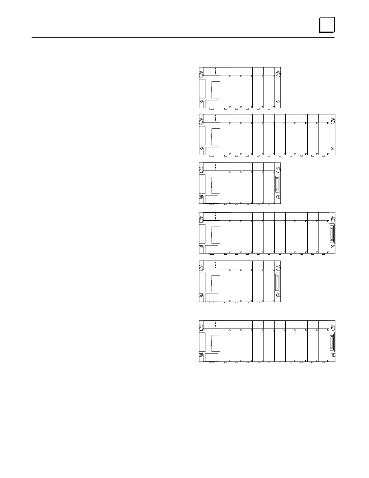
CPU baseplate. The next figure identifies where you can locate the modules in your
system.
Power Supply capacity - Since some modules draw considerably more power than
others, it is possible to overload the power supply by placing many of the modules
requiring higher power in one rack. Therefore, before finalizing your rack layout
you should calculate the power supply loading to ensure that you will not overload
the power supply. See the section “Calculating Power Supply Loading.”
Noise Reduction - Group I/O modules to keep Output modules separated from
sensitive Input modules. This will facilitate keeping noisy wiring separated from
sensitive wiring, as recommended in a previous section.
12-18
Series 90-30 PLC Installation and Hardware Manual-October 1999
GFK-0356P
12
Allowable Module Locations
DISCRETE INPUT/OUTPUT
a43086A
ANALOG INPUT/OUTPUT
ÎÎÎÎÎÎÎ
HIGH SPEED COUNTER
MODEL 311/313
I/O PROCESSOR
ÎÎÎÎÎÎÎ
(5-SLOT)
GENIUS COMMUNICATIONS
ENHANCED GENIUS COMM.
MOTION MATE APM300/DSM302
ÎÎÎÎÎÎÎ
I/O LINK INTERFACE
GENIUS BUS CONTROLLER
ÎÎÎÎÎÎÎ
ETHERNET INTERFACE
TEMPERATURE CONTROL
ÎÎÎÎÎ
ÎÎ
DISCRETE INPUT/OUTPUT
ANALOG INPUT/OUTPUT
ÎÎÎÎÎÎÎÎÎÎÎÎ
HIGH SPEED COUNTER
I/O PROCESSOR
MODEL 313
ÎÎÎÎÎÎÎÎÎÎÎÎÎ
GENIUS COMMUNICATIONS
(10-SLOT)
ENHANCED GENIUS COMM.
MOTION MATE APM300/DSM302
ÎÎÎÎÎÎÎÎÎÎÎÎÎ
I/O LINK INTERFACE
GENIUS BUS CONTROLLER
ÎÎÎÎÎÎÎÎÎÎÎÎÎ
ETHERNET INTERFACE
TEMPERATURE CONTROL
ÎÎÎÎÎÎÎÎÎÎÎÎÎ
DISCRETE INPUT/OUTPUT
ANALOG INPUT/OUTPUT
HIGH SPEED COUNTER
I/O PROCESSOR
ÎCÎÎÎÎÎ
MODEL 331/340/341
GENIUS COMMUNICATIONS
and 350/351/352/360/
ENHANCED GENIUS COMM.
ÎUÎÎÎÎÎ
363/364 5-Slot CPU
MOTION MATE APM300/DSM302
I/O LINK INTERFACE
PCM / ADC / CMM / SLP
ÎÎÎÎÎÎÎ
GENIUS BUS CONTROLLER
ETHERNET INTERFACE
ÎÎÎÎÎÎÎ
TEMPERATURE CONTROL
DISCRETE INPUT/OUTPUT
ANALOG INPUT/OUTPUT
HIGH SPEED COUNTER
ÎÎÎÎÎÎÎÎÎÎÎÎÎ
MODEL 331/340/341
I/O PROCESSOR
C
and 350/351/352/360/
GENIUS COMMUNICATIONS
ÎPÎÎÎÎÎÎÎÎÎÎÎ
ENHANCED GENIUS COMM.
U
363/364 10-Slot CPU
MOTION MATE APM300/DSM302
ÎÎÎÎÎÎÎÎÎÎÎÎÎ
I/O LINK INTERFACE
GENIUS BUS CONTROLLER
ETHERNET INTERFACE
ÎÎÎÎÎÎÎÎÎÎÎÎÎ
TEMPERATURE CONTROL
PCM / ADC / CMM / SLP
DISCRETE INPUT/OUTPUT
ANALOG INPUT/OUTPUT
ÎÎÎÎÎÎÎ
HIGH SPEED COUNTER
I/O PROCESSOR
ÎÎÎÎÎÎÎ
MODEL 331/340/341
GENIUS COMMUNICATIONS
and 350/351/352/360/
ENHANCED GENIUS COMM.
MOTION MATE APM300/DSM302
ÎÎÎÎÎÎÎ
363/364 5-Slot Expansion
I/O LINK INTERFACE
GENIUS BUS CONTROLLER
ÎÎÎÎÎÎÎ
ETHERNET INTERFACE
TEMPERATURE CONTROL
ÎÎÎÎÎÎÎ
DISCRETE INPUT/OUTPUT
ANALOG INPUT/OUTPUT
ÎÎÎÎÎÎÎÎÎÎÎÎ
HIGH SPEED COUNTER
I/O PROCESSOR
ÎÎÎÎÎÎÎÎÎÎÎÎÎ
GENIUS COMMUNICATIONS
MODEL 331/340/341
ENHANCED GENIUS COMM.
MOTION MATE APM300/DSM302
ÎÎÎÎÎÎÎÎÎÎÎÎÎ
and 350/351/352/360/
I/O LINK INTERFACE
363/364 10-Slot Expansion
GENIUS BUS CONTROLLER
ÎÎÎÎÎÎÎÎÎÎÎÎÎ
ETHERNET INTERFACE
TEMPERATURE CONTROL
ÎÎÎÎÎÎÎÎÎÎÎÎÎ
* For location of FIP modules in baseplates, refer to the applicable FIP module user’s manual.
Figure 12-2. Allowable Location of Modules
GFK-0356P
Chapter 12 System Design
12-19
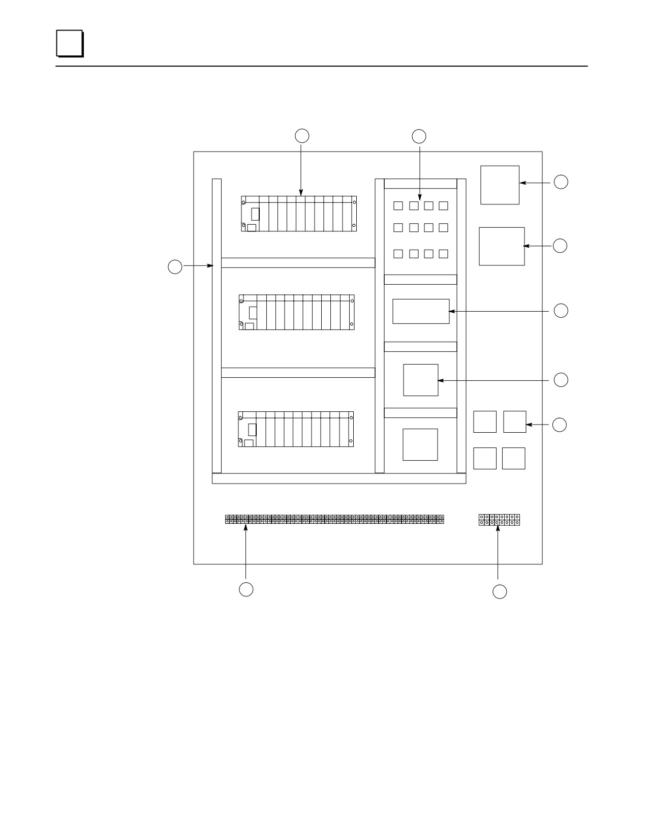
12
Series 90-30 PLC Layout Example
1
10
9
8
2
7
6
5
3
4
Figure 12-3. Series 90-30 Example Layout
1.
Series 90-30 PLC, 10-slot rack
2.
Wireway (Wire Duct)
3.
Field device connection terminal block
4.
Motor connection terminal block
5.
Motor starters
6.
Circuit board
7.
Power supply
8.
Control transformer
9.
Fusible disconnect or circuit breaker
10. Control relays
12-20
Series 90-30 PLC Installation and Hardware Manual-October 1999
GFK-0356P
12
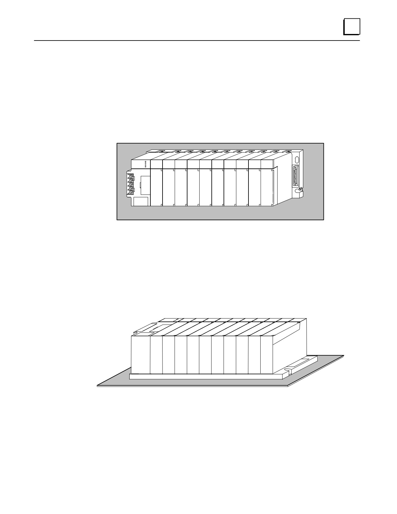
PLC Mounting Position
Power supply load rating depends on the mounting position of the baseplate and the
ambient temperature.
Recommended Upright Mounting Orientation
The load rating with the baseplate mounted upright on a panel is:
100% at 60 C (140 F)
ÎÎ
ÎÎ
Î
ÎÎ
Figure 12-4. Recommended PLC Mounting Orientation
Derated Horizontal Mounting Orientation
Power supply load ratings with the baseplate mounted horizontally are:
temperature at 25 C (77 F) - full load
temperature at 60 C (140 F) - 50% of full load
Figure 12-5. Derated PLC Mounting Orientation
GFK-0356P
Chapter 12 System Design
12-21
Chapter
Maintenance and Troubleshooting
13
Troubleshooting Features of Series 90-30 Hardware
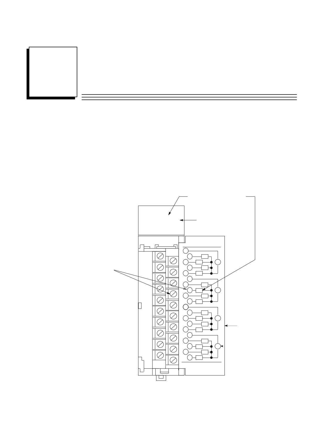
Indicator Lights (LEDs) and Terminal Board
The following figure shows how the indicator LEDs correspond to the circuit connection
points on an I/O Module’s terminal board. The terminal board terminals are numbered
from the top, with the top terminal in the left row being number 1 and the top terminal
in the right row being number 2. The numbers alternate between rows with even
numbers on the right and odd numbers on the left, as shown in the circuit diagram on
the back of the hinged cover.
LED A6 corresponds to circuit A6:
A1 2 3 4 5 6 7 8
F
Fuse Indicator LED
B1 2 3 4 5 6 7 8
ÎÎÎÎÎÎ
OUTPUT
ÎRELAY N.O2 AMPÎ
Î1ÎÎÎÎÎ
2
A1
Î3ÎA2ÎÎVÎ
Circuit A6 connects
ÎÎÎA3ÎÎÎ
to terminal 8
5
A4
6
ÎÎÎÎÎÎ
Î7ÎÎA5ÎÎÎ
8
A6
V
Î9ÎÎA7ÎÎÎ
Î10ÎA8ÎÎÎ
11
Î12ÎÎB1ÎÎÎ
13Î B2 ÎÎV Î
14
B3
Hinged Cover
15Î B4 ÎÎÎ
Î16ÎÎÎÎÎ
17
B5
Î18ÎB6ÎÎVÎ
Indicates External
Power Supply
19ÎÎB7ÎÎÎ
20
B8
ÎÎÎÎÎÎ
44A726782-015
ÎÎFIC693MDL940 Î a43082B
ÎÎÎÎÎÎ
Figure 13-1. Relationship of Indicator Lights to Terminal Board Connections
13-1
GFK-0356P
13
Module LED Indicators
Input Module LED Indicators
When a discrete input device closes, the corresponding input LED should light to
indicate that the signal reached the module. If the light does not turn ON, a voltage
check can be made on the module’s terminal board or block:
If the correct voltage is present at the terminal, the corresponding input bit can
be checked in the PLC with your programming software. If the software shows
that the input bit is at logic 1, the module’s LED circuit is defective.
If the correct voltage level is not present at the terminal, a check can be made at
the input field device to determine if the device or interconnecting wiring is
defective.
If none of an input module’s inputs are working, it may be that the external (field) input
power supply is defective, is not powered up, or is not connected properly. (As indicated
in the connections diagram in the previous figure, input and output devices are powered
from an external power supply, not from inside the module). Input modules are not
fused, so the Fuse Indicator LED in the previous picture does not apply to them.
Output Module LED Indicators
When a discrete output address (%Q) is turned on in the ladder program, the
corresponding output LED should light to indicate that the signal reached the module.
If the light does not turn ON, the module may be defective or the LED light may
be bad.
If the light turns on but the output device doesn’t operate, a voltage check can
be made on the module’s terminal board or block. If the correct voltage level is
present there, a check could be made of the output device or wiring.
If none of an output module’s outputs are working, it may be that the external (field)
output power supply is defective, is not powered up. or is not connected properly.
(As
indicated in the connection diagram in the previous figure, input and output devices are
powered from an external power supply, not from inside the module). If the output
module is a type that has built-in fuses (some have electronic short circuit protection
instead), the Fuse Indicator LED (labeled “F”), shown in the previous picture, will light if
a fuse blows.
Power Supply LED Indicators
The power supplies have four LED indicators. Their functions are explained in the
“Power Supplies” chapter.
CPU LED Indicators
There are several different LED arrangements on the various CPUs. These are explained
in the “CPUs” chapter.
Option Module LED Indicators
There are numerous LED arrangements on the various option modules. The “Option
Modules” chapter has some information on this subject. It also directs you, for each
module, to further information in the “Documentation” heading for each module. Also,
Appendix I contains a catalog number to documentation cross-reference.
13-2
Series 90-30 PLC Installation and Hardware Manual - October 1999
GFK-0356P
13
Troubleshooting Features of Programming Software
Detailed information about the following items are found in GFK-0467, Series
90-30/20/Micro PLC CPU Instruction Set Reference Manual, and GFK-0466, Series
90-30/20/Micro Programming Software User’s Manual.
Ladder Screens
Contacts, connections, and coils displayed on the ladder screens that are ON (passing
power or energized) are displayed in enhance brightness, allowing the tracing of signals
through the program. Addresses that refer to physical input (%I and %AI) and output
signals (%Q and %AQ) can be checked against module status lights, voltages, etc. to
verify that the hardware is working properly.
Configuration Screens
Normally, the following information is obtained from the system documentation.
However, if they are not available, the configuration screens can be used to determine:
If the software configuration matches the actual hardware. Sometimes, while
troubleshooting, a module is installed in an incorrect slot by mistake. This will create
a fault in one of the two fault tables. The correct configuration can be determined
from the Configuration Screens.
The memory addresses that a particular module is using.
Fault Tables
There are two fault tables, the “PLC Fault Table,” and the “I/O Fault Table.” The fault
tables can be viewed using the PLC programming software. These fault tables will not
report such things as a defective limit switch, but will identify system faults such as:
Loss of or Missing Modules, System Configuration Mismatch.
CPU hardware failure, Low Battery
PLC Software Failure, Program Checksum Failure, No User Program, PLC Store
Failures.
System Status References
These discrete references (%S, %SA, %SB, and %SC) can be viewed in the System
Reference (Status) Table, or on-screen if used in the ladder program, for determining the
status of various conditions and faults. For example, the %SC0009 bit turns on if a fault
is logged in either fault table. Another example is that bit %SA0011 will turn on if the
CPU memory backup battery is low. The Series 90-30 PLC CPU Instruction Set Reference
Manual, GFK-0467, includes a “System Status Reference Table.”
Reference Tables
There are two types of reference tables, standard and mixed. These tables show groups
of memory addresses and their status. For discrete addresses, the status of these will be
shown as either logic 1 or logic 0. For analog and register addresses, values will be
displayed. Standard tables display only one type of memory address, such as all of the
%I bits. Mixed reference tables are created by the user, who selects what addresses to
display in the tables. These mixed tables can contain discrete, analog, and register
GFK-0356P
Chapter 13 Maintenance and Troubleshooting
13-3
13
references all in one table. This makes them useful for gathering numerous related
addresses on one screen where they can all be viewed or monitored at the same time.
This saves time compared with searching or scrolling through the ladder logic screens to
find these addresses.
Override feature
This feature must be used with caution to ensure the safety of personnel and
equipment. Normally, the machine should not be cycling, and all conditions should be
such that the output device can be turned on without any harm being done. This
method can be used to check an output circuit from the ladder screen all the way to the
device being controlled. For example, when overriding and toggling a %Q output to an
ON state, the relay, solenoid, or other device being controlled should turn on or pick up.
If it does not, the status light on the output module could be checked, then voltage
checks could be made at the module terminal board, the system terminal strip, the
machinery terminal strip, the solenoid or relay connections, etc. until the source of the
fault is found.
Sequential Event Recorder (SER), DOIO functional instruction
These can be set up to capture the status of specified discrete addresses upon receiving a
trigger signal. They may be used to monitor and capture data about certain portions of
the program, even when unattended. They can be useful for locating the cause of an
intermittent problem. For example, a contact in a string of contacts that maintain power
to a coil may, from time to time, momentarily open and interrupt normal operation.
However, when maintenance personnel attempt to locate the problem, all of these
contacts may test OK. By using the SER or DOIO instruction, the status of all of these
contacts can be captured within milliseconds of the time the fault occurs, and the contact
that opened will show a status of logic 0 at the moment of capture.
Replacing Modules
Modules do not contain configuration switches. The slot in each baseplate (rack) is
configured (using the configuration software) to hold a particular module type (catalog
number). This configuration information is stored in CPU memory. Therefore, when
replacing a module, you do not have to make any hardware settings on the module
itself. You do, however, have to ensure that you install the correct module type in a
particular slot.
Be aware that some “intelligent” modules, such as the CPU, PCM, APM, or DSM302,
may contain application programs that will need to be reloaded after the module is
replaced. For such modules, make sure that up-to-date copies of the application
programs are maintained in case they have to be restored later.
For I/O modules with terminal boards, you do not have to rewire a new terminal board
in order to replace the module. If the old terminal board is not defective, it can be
removed from the old module and reinstalled on the new module without removing
any of the wiring. Procedures for removing and installing modules and terminal boards
are found in Chapter 2.
Series 90-30 Product Repair
The Series 90-30 products are, for the most part, not considered to be field-repairable.
The one major exception are the few modules that have replaceable fuses. The next
section, “Module Fuse List,” identifies these modules and their applicable fuses.
GE Fanuc offers a repair/product warranty service through your local distributor.
Contact you distributor for details.
13-4
Series 90-30 PLC Installation and Hardware Manual - October 1999
GFK-0356P