FANUC Series 30i-MODEL B, 31i-MODEL B, 32i-MODEL B. For Machining Center System. OPERATOR'S MANUAL - page 2
3.INTERPOLATION FUNCTION
PROGRAMMING
B-64484EN-2/02
Example
C (Imaginary axis)
Path after tool
compensation
Programmed path
N204
C-axis
N205
Tool
X-axis
N201
N202
N200
Z-axis
N203
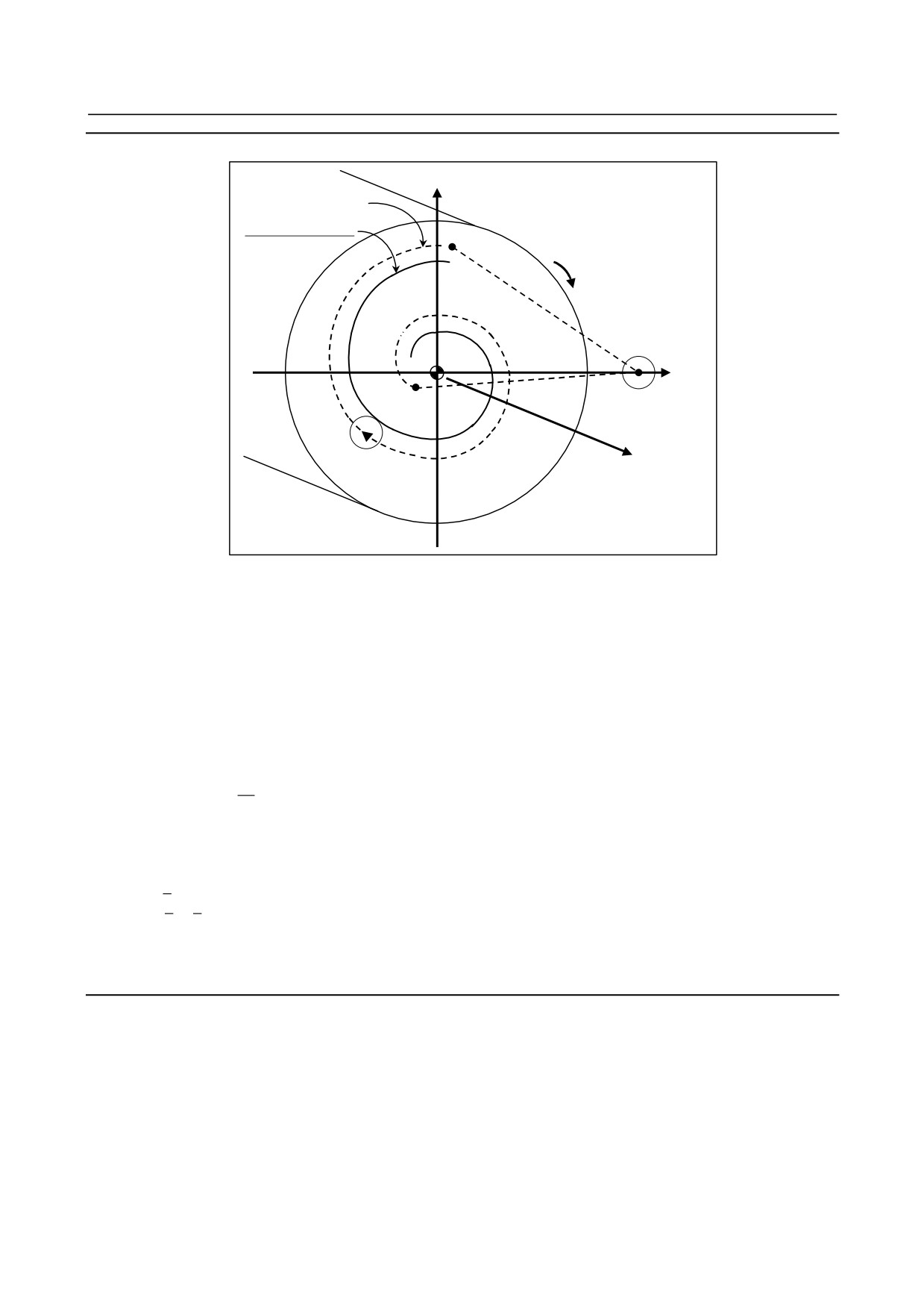
Fig. 3.1 (e) Involute interpolation in the polar coordinate interpolation mode
O0001 ;
:
:
N010 T0101 ;
:
:
N100 G90 G00 X15.0 C0 Z0 ;
Positioning to the start point
N200 G12.1 ;
Polar coordinate interpolation started
N201 G41 G00 X-1.0 ;
N202 G01 Z-2.0 F
;
N203 G02.2 X1.0 C9.425 I1.0 J0 R1.0 ; Involute interpolation during polar coordinate interpolation
N204 G01 Z0 ;
N205 G40 G00 X15.0 C0 ;
N206 G13.1 ;
Polar coordinate interpolation cancelled
N300 Z
;
N400 X
C
;
:
:
M30 ;
Limitation
-
Number of involute curve turns
Both the start point and end point must be within 100 turns from the point where the involute curve starts.
An involute curve can be specified to make one or more turns in a single block.
If the specified start point or end point is beyond 100 turns from the point where the involute curve starts,
alarm PS0242 is issued.
-
Unspecifiable functions
In involute interpolation mode, optional chamfering and corner R cannot be specified.
- 22 -
B-64484EN-2/02
PROGRAMMING
3.INTERPOLATION FUNCTION
-
Mode that does not allow involute interpolation specification
Involute interpolation cannot be used in the following mode:
G07.1: Cylindrical interpolation
3.2
THREADING (G33)
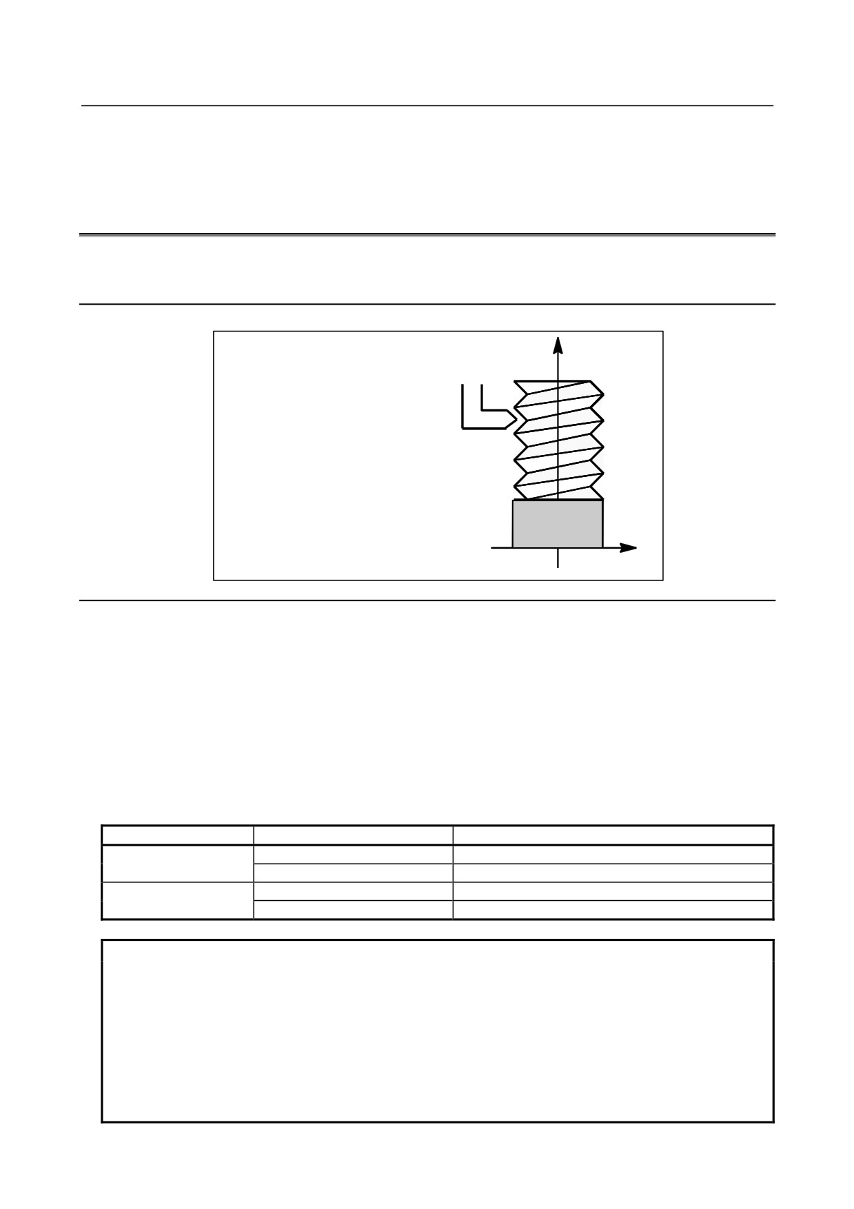
Straight threads with a constant lead can be cut. The position coder mounted on the spindle reads the
spindle speed in real-time. The read spindle speed is converted to the feedrate per minute to feed the tool.
Format
Z
G33IP_ F_ ;
F : Long axis direction lead
Workpiece
X
Explanation
In general, threading is repeated along the same tool path in rough cutting through finish cutting for a
screw. Since threading starts when the position coder mounted on the spindle outputs a 1-turn signal,
threading is started at a fixed point and the tool path on the workpiece is unchanged for repeated
threading. Note that the spindle speed must remain constant from rough cutting through finish cutting. If
not, incorrect thread lead will occur.
In general, the lag of the servo system, etc. will produce somewhat incorrect leads at the starting and
ending points of a thread cut. To compensate for this, a threading length somewhat longer than required
should be specified.
Table 3.2 (a) lists the ranges for specifying the thread lead.
Table 3.2 (a) Ranges of lead sizes that can be specified
Least command increment
Command value range of the lead
0.001 mm
F1 to F50000 (0.01 to 500.00mm)
Metric input
0.0001 mm
F1 to F50000 (0.01 to 500.00mm)
0.0001 inch
F1 to F99999 (0.0001 to 9.9999inch)
Inch input
0.00001 inch
F1 to F99999 (0.0001 to 9.9999inch)
NOTE
1 The spindle speed is limited as follows :
1 ≤ spindle speed ≤ (Maximum feedrate) / (Thread lead)
Spindle speed : min-1
Thread lead : mm or inch
Maximum feedrate : mm/min or inch/min ; maximum command-specified
feedrate for feed-per-minute mode or maximum feedrate that is determined
based on mechanical restrictions including those related to motors, whichever is
smaller
- 23 -
3.INTERPOLATION FUNCTION
PROGRAMMING
B-64484EN-2/02
NOTE
2 Cutting feedrate override is not applied to the converted feedrate in all machining
process from rough cutting to finish cutting. The feedrate is fixed at 100%
3 The converted feedrate is limited by the upper feedrate specified.
4 Feed hold is disabled during threading. Pressing the feed hold key during
threading causes the machine to stop at the end point of the next block after
threading (that is, after the G33 mode is terminated)
Example
Threading at a pitch of 1.5mm
G33 Z10. F1.5;
3.3
CONTINUOUS THREADING
Threading blocks can be programmed successively to eliminate a discontinuity due to a discontinuous
movement in machining by adjacent blocks.
Explanation
Since the system is controlled in such a manner that the synchronism with the spindle does not deviate in
the joint between blocks wherever possible, it is possible to performed special threading operation in
which the lead and shape change midway.
G33
G33
G33
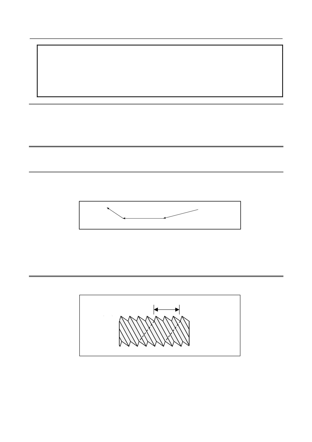
Fig. 3.3 (a) Continuous threading
Even when the same section is repeated for thread cutting while changing the depth of cut, this system
allows a correct machining without impairing the threads.
3.4
MULTIPLE THREADING
Using the Q address to specify an angle between the one-spindle-rotation signal and the start of threading
shifts the threading start angle, making it possible to produce multiple-thread screws with ease.
L
L : Lead
Fig. 3.4 (a) Multiple thread screws
- 24 -

B-64484EN-2/02
PROGRAMMING
3.INTERPOLATION FUNCTION
Format
(Constant lead threading)
G33 IP _ F_ Q_ ;
IP : End point
F_ : Lead in longitudinal direction
G33 IP _ Q_ ;
Q_ : Threading start angle
Explanation
-
Available threading commands
G33: Constant lead threading
G34: Variable lead threading
G76.7: Multiple threading cycle
Limitation
-
Start angle
The start angle is not a continuous state (modal) value. It must be specified each time it is used. If a
value is not specified, 0 is assumed.
-
Start angle increment
The start angle (Q) increment is 0.001 degrees. Note that no decimal point can be specified.
Example:
For a shift angle of 180 degrees, specify Q180000.
Q180.000 cannot be specified, because it contains a decimal point.
-
Specifiable start angle range
A start angle (Q) of between 0 and 360000 (in 0.001-degree units) can be specified. If a value
greater than 360000 (360 degrees) is specified, it is rounded down to 360000 (360 degrees).
-
Multiple threading cycle (G76.7)
For the G76 multiple threading cycle command, always use the FS15 tape format.
Example
Program for producing double-threaded screws (with start angles of 0 and
180 degrees)
G00 X40.0 ;
G33 W-38.0 F4.0 Q0 ;
G00 X72.0 ;
W38.0 ;
X40.0 ;
G33 W-38.0 F4.0 Q180000 ;
G00 X72.0 ;
W38.0 ;
- 25 -
3.INTERPOLATION FUNCTION
PROGRAMMING
B-64484EN-2/02
3.5
CIRCULAR THREAD CUTTING B (G2.1,G3.1)
Overview
Circular thread cutting B can perform circular interpolation on two axes and, at the same time, can
perform linear interpolation between the major axis of the two axes subject to circular interpolation,
which has a longer traveling distance, and up to two other, arbitrary axes. This circular thread cutting
function does not move the tool in synchronization with the rotation of the spindle (workpiece) using the
spindle motor, but controls the rotation of the workpiece using a servo motor (rotation axis) to perform
threading at equal pitches along cylindrical material, grooving, tool grinding, and other machining.
Application example
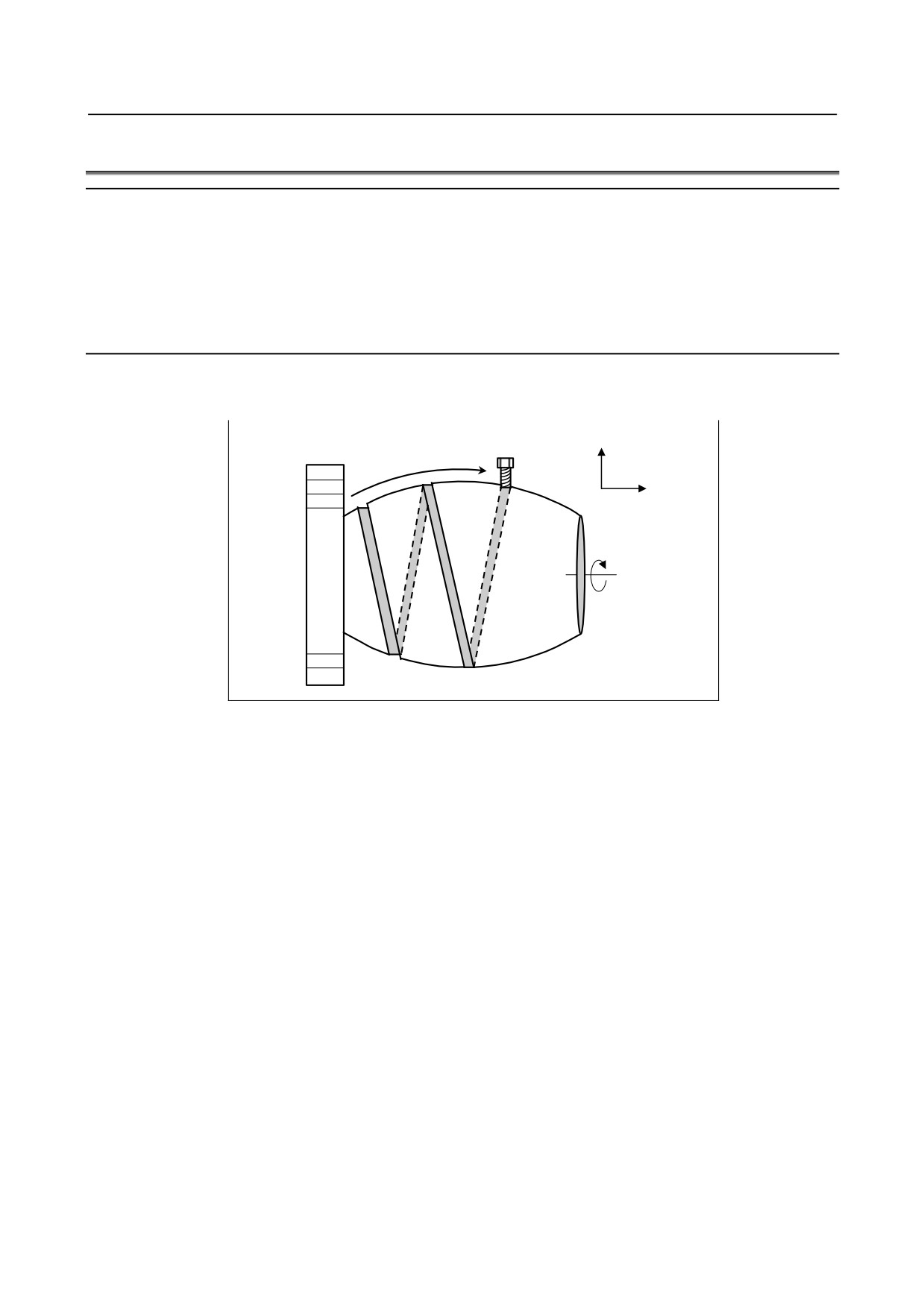
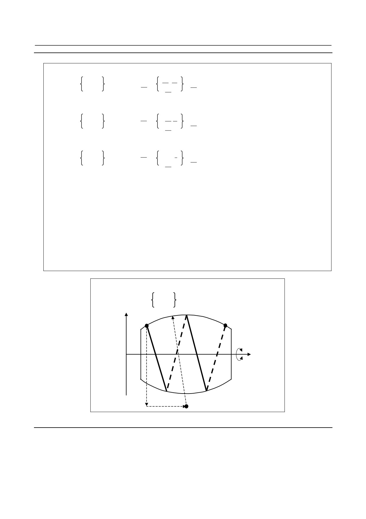
For example, the grooving shown in Fig. 3.5 (a) can be performed by executing circular interpolation on
the ZpXp plane in synchronization with linear interpolation on the Z-axis and the C-axis.
X axis
Z axis
C axis
Fig. 3.5 (a) Example of grooving
- 26 -
B-64484EN-2/02
PROGRAMMING
3.INTERPOLATION FUNCTION
Format
Xp-Yp plane
G02.1
I
J
G17
X Y α β
F
;
G03.1
R
Zp-Xp plane
G02.1
Z X α β
K I
G18
F
;
G03.1
R
Yp-Zp plane
G02.1
Y Z α β
J K
G19
F
;
G03.1
R
G02.1: Clockwise circular thread cutting B command
G03.1: Counterclockwise circular thread cutting B command
X,Y,Z: Coordinates of the end point for circular interpolation
α,β:
Coordinates of the end point for linear interpolation
I,J,K:
Signed distance from the start point to the center of an arc
R:
Arc radius
F:
Feedrate in the major axis direction
α and β are arbitrary axes other than the circular interpolation axis. Up to two such axes
can be specified.
X, Y, Z, I, J, K, and R are the same as those for G02 and G03.
In the case of the ZpXp plane, the major axis being the Z-axis, the minor axis
being the X-axis, the arbitrary axis being the C-axis, and clockwise direction
G91 G18 G02.1 Z_ C_
I_ K_
F_
R_
X axis
Start point
End point (X,Z)
C axis
Z axis
R
I
K
Arc center
Fig. 3.5 (b)
Explanation
Circular thread cutting B can perform circular interpolation on two axes and, at the same time, can
perform linear interpolation between the major axis of the two axes subject to circular interpolation,
which has a longer traveling distance, and up to two other, arbitrary axes. This circular thread cutting
function does not move the tool in synchronization with the rotation of the spindle (workpiece) using the
spindle motor, but controls the rotation of the workpiece using a servo motor (rotation axis) to perform
threading at equal pitches along cylindrical material, grooving, tool grinding, and other machining.
- 27 -
3.INTERPOLATION FUNCTION
PROGRAMMING
B-64484EN-2/02
-
Relationship between major axis and minor axis
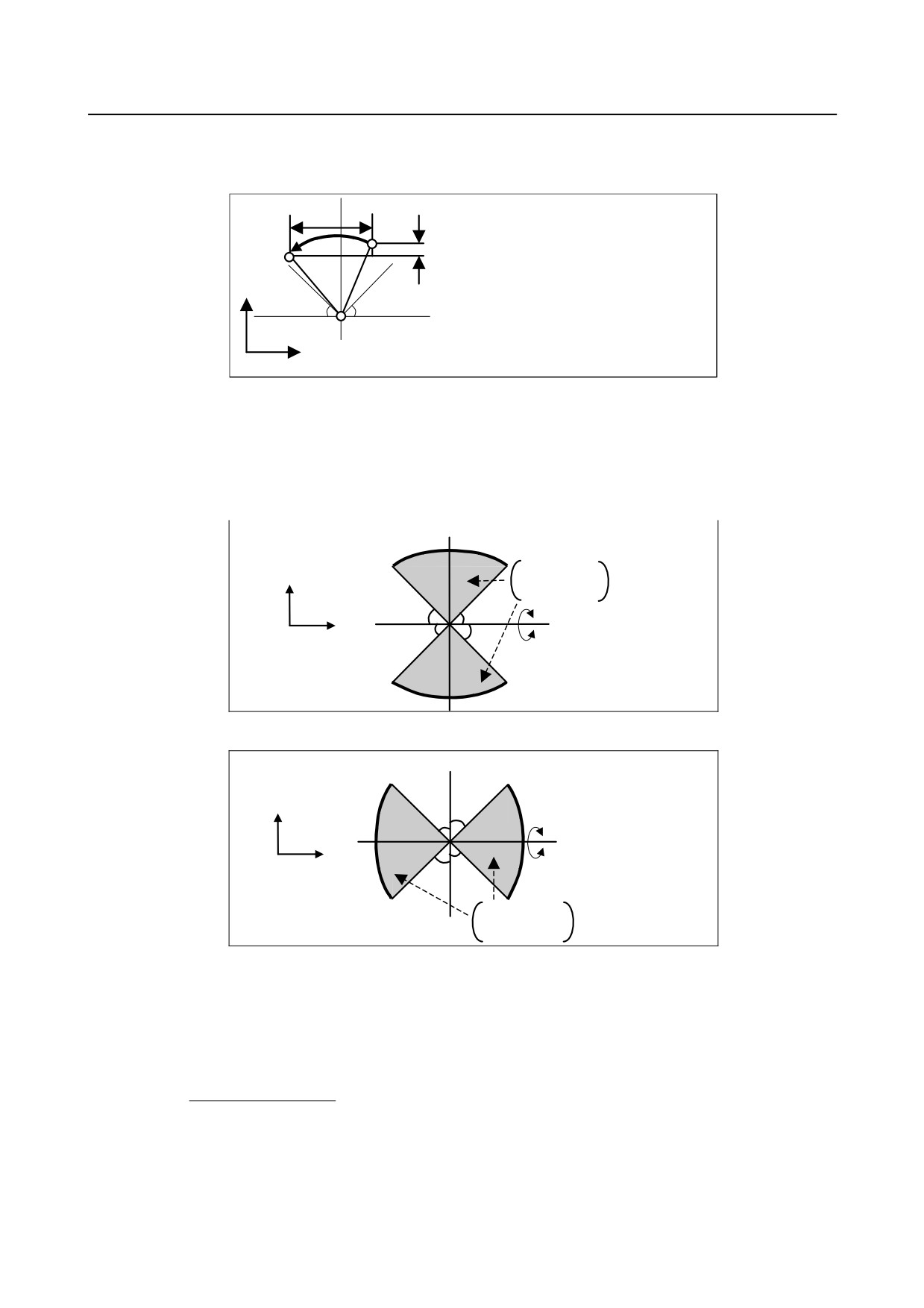
The relationship between the major axis and minor axis is as shown in Fig. 3.5 (c).
ΔX
Start
End
point
If |ΔX| > |ΔY|,
point
ΔY
the major axis is the X-axis, and the
minor axis is the Y-axis.
Y
If |ΔX| < |ΔY|,
45°
45°
the major axis is the Y-axis, and the
Center
minor axis is the X-axis.
X
Fig. 3.5 (c)
When diameter programming is used, the relationship between the major axis and minor axis is judged
with the radius value.
-
Permissible arc range
If the arc goes beyond the range shown in Fig. 3.5 (d) or Fig. 3.5 (e), alarm PS2070 is issued.
90°
Minor
Range in which
45° to 135°
axis
interpolation is
225° to 315°
enabled
45°
45°
0°
Major
45°
45°
Rotation
axis
axis
Fig. 3.5 (d)
90°
Major
axis
45°
45°
0°
Minor
Rotation
45°
45°
axis
axis
315° to 45°
Range in which
135° to 225°
interpolation is enabled
Fig. 3.5 (e)
-
Feedrate
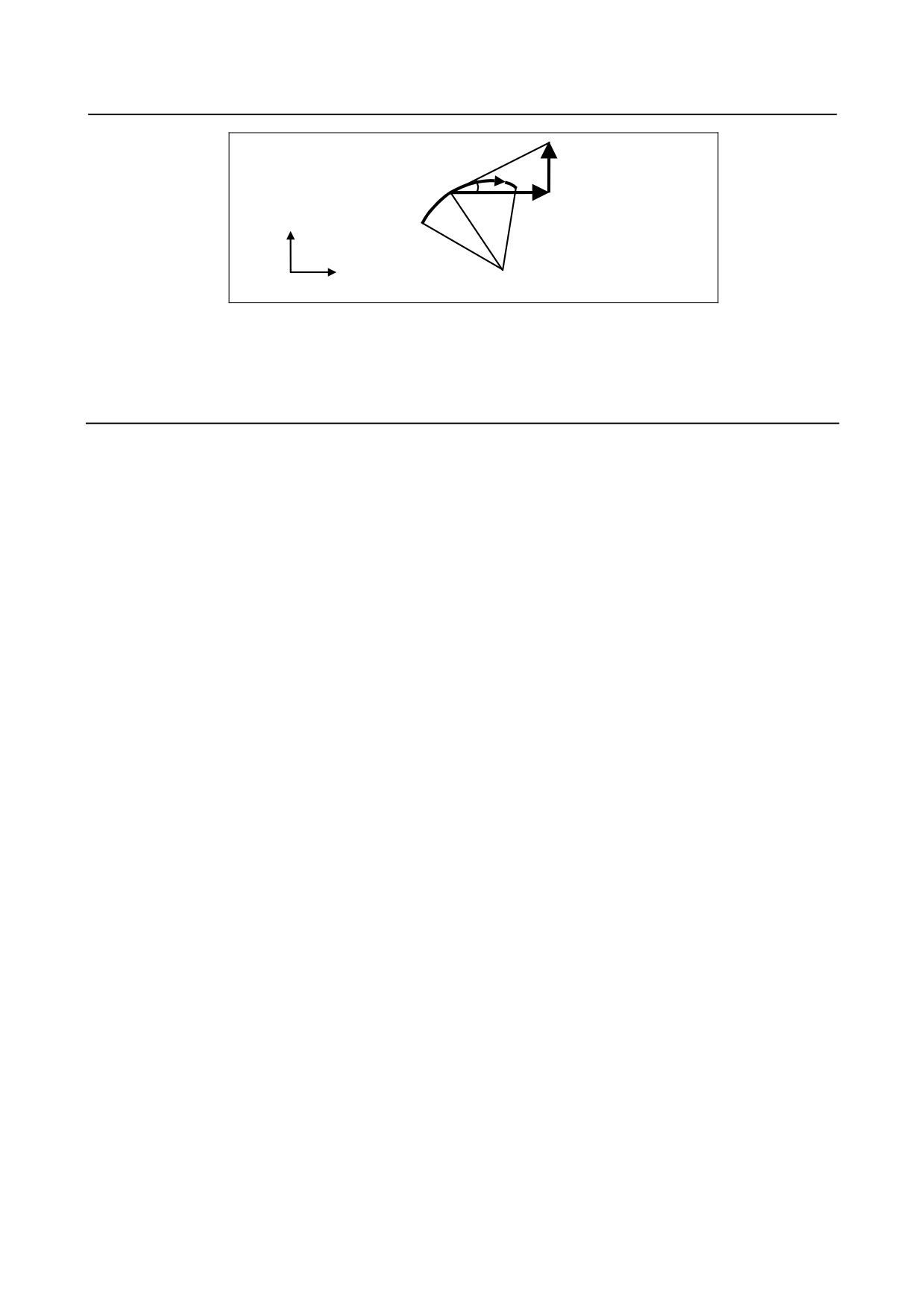
If the specified feedrate for the major axis is F, the feedrate for the minor axis Fs and feedrate for the α
axis Fα are expressed as follows.
Length of α axis
Fα = F ×
(The maximum value is the maximum cutting feedrate for each axis.)
Length of major axis
Fs = F × TAN θ
θ: Angle of a tangent to the major axis
- 28 -
B-64484EN-2/02
PROGRAMMING
3.INTERPOLATION FUNCTION
End
Fs
θ
point
Minor
F
axis
Start point
Major
axis
Center
Fig. 3.5 (f)
-
Tool radius compensation
Tool radius compensation applies only to two axes of the plane on which circular interpolation is
performed.
Limitation
-
Tool offset and tool length compensation
In a block in which circular thread cutting B is specified, tool offset or tool length compensation cannot
be specified.
-
I,J,K and the R command
Either I,J,K or the R command cannot be omitted.
-
Unavailable functions
Circular thread cutting B cannot be used together with the following functions:
•
3-dimensional cutter compensation
•
Tool center point control
- 29 -
3.INTERPOLATION FUNCTION
PROGRAMMING
B-64484EN-2/02
3.6
GROOVE CUTTING BY CONTINUOUS CIRCLE MOTION
(G12.4, G13.4)
Overview
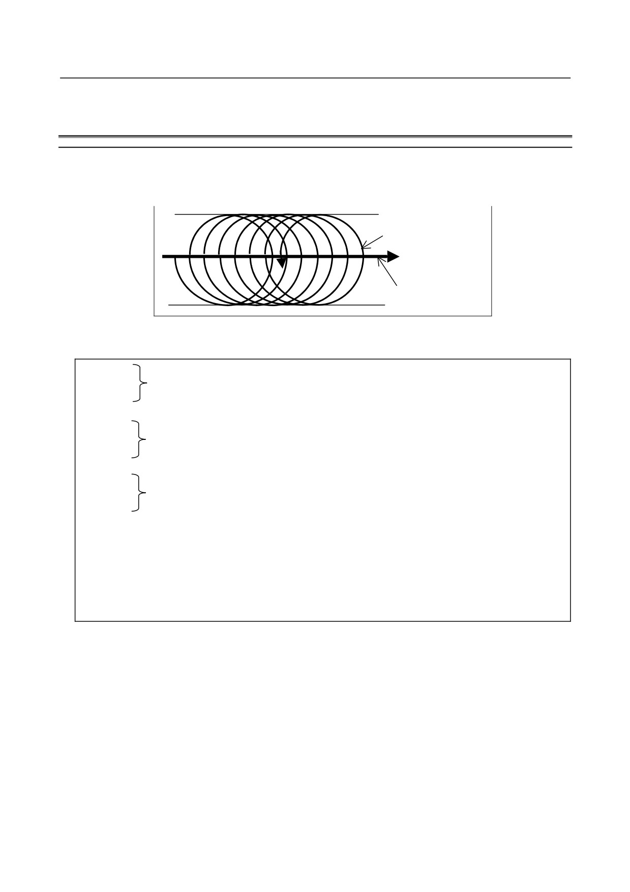
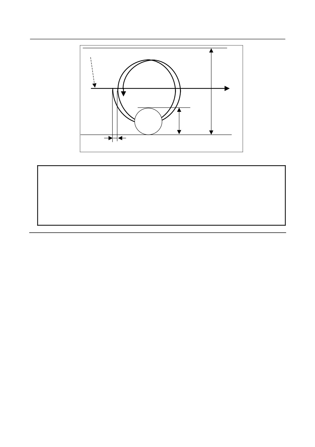
Groove cutting with a width greater than the tool diameter can be performed by causing the tool to make
continuous circle motion independently of axis movement by the groove cutting path program and
superposing the continuous circle motion on the axis movement by the groove cutting path program.
Continuous
circle motion
Groove cutting path
specification route
Fig. 3.6 (a)
Format
G12.4
P1Ii Kk Qq Ff;
(Mode on)
G13.4
:
:
(Groove cutting path program)
:
G12.4
P0;
(Mode cancel)
G13.4
G12.4 : Clockwise continuous circle motion
G13.4 : Counterclockwise continuous circle motion
i
: Groove width
k
: Tool diameter
q
: Travel distance in the groove cutting direction per continuous circle motion (pitch)
f
: Feedrate (speed of the center of a tool that performs continuous circle motion)
- 30 -
B-64484EN-2/02
PROGRAMMING
3.INTERPOLATION FUNCTION
Groove cutting path program
i
(Groove width)
k (Tool diameter)
q (pitch)
Fig. 3.6 (b)
NOTE
1 In the G12.4/G13.4 blocks, addresses other than the commands mentioned
above cannot be used.
2 If bit 4 (GCC) of parameter No. 3452 is 0, continuous circle motion stops due to
the stoppage of axis movement by the groove cutting path program, but because
axis movement by the groove cutting path program is independent of continuous
circle motion, the stoppage will not exactly be at the position of continuous circle
motion converted from the groove cutting path program and the pitch.
Explanation
-
Mode on
The continuous circle motion-based groove cutting mode sets continuous circle motion-based groove
cutting mode to the on state. The continuous circle motion-based groove cutting enable signal must be
"1".
If the mode on command is specified with the continuous circle motion-based groove cutting enable
signal being "0", alarm PS0010 is issued.
No axis movement is performed with the continuous circle motion-based groove cutting mode on
command.
-
Mode cancel
The continuous circle motion-based groove cutting mode cancel command causes the tool to move with
cutting feed (continuous circle motion speed) from the present position on the continuous circle to the
end-specified position (groove center) of the groove cutting path program. After the end of movement, the
command sets continuous circle motion-based groove cutting mode to the cancel state.
-
Startup
In the first move command block of the groove cutting path program, the tool moves to a point on the
continuous circle with cutting feed (continuous circle motion speed). After the end of the movement to a
point on the continuous circle, continuous circle motion is started in synchronization with the move
command of the groove cutting path program.
Depending on the first move command block of the groove cutting path program, the direction of startup
varies.
- 31 -
3.INTERPOLATION FUNCTION
PROGRAMMING
B-64484EN-2/02
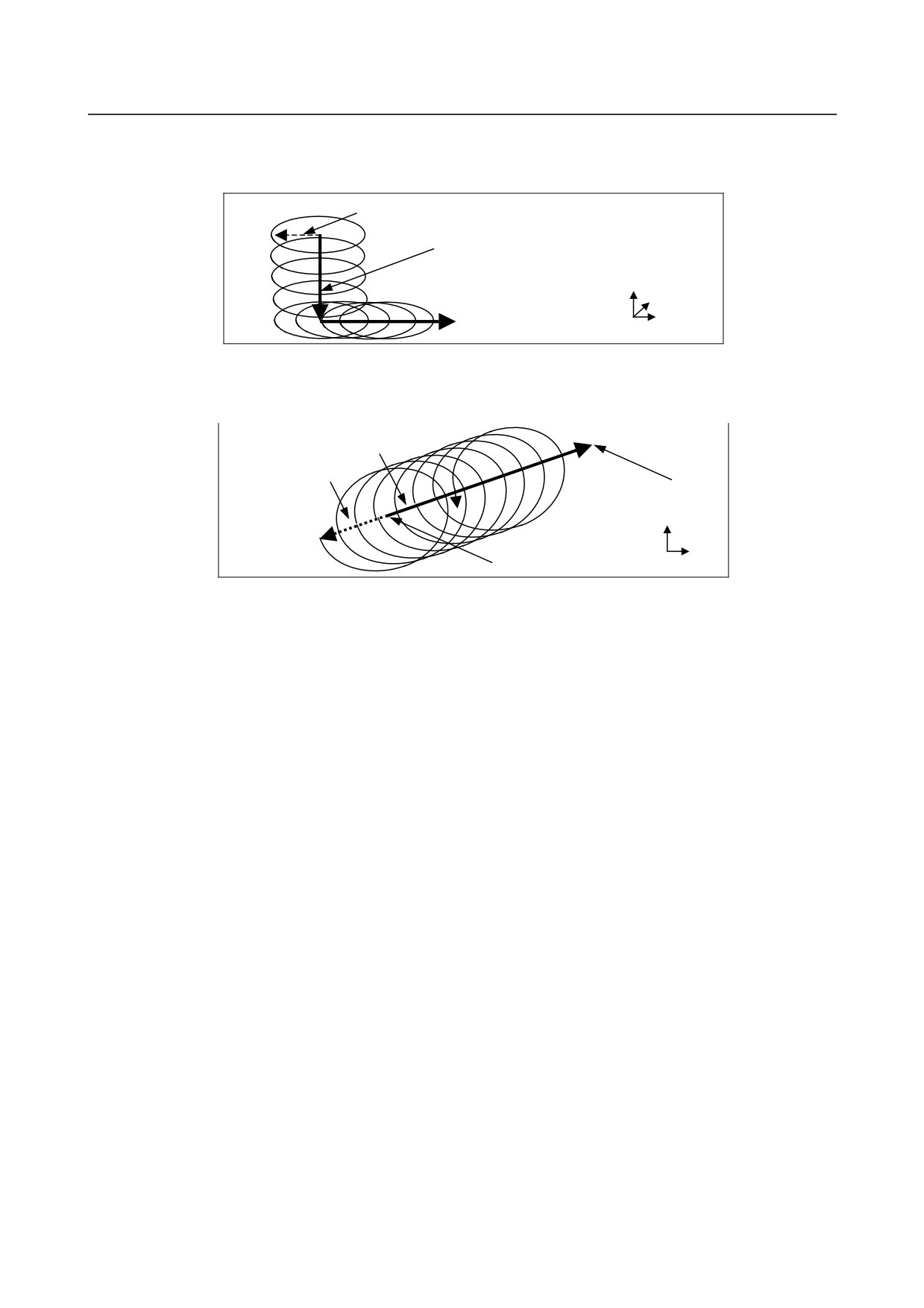
• In the case of an axis command perpendicular to a plane or if there is no movement along an axis
used to form the currently selected plane
Assuming that R = (I-K)/2, the following holds true: (X,Y) = (-R,0)
Startup
R
Groove cutting
path command
Z
Y
X
Fig. 3.6 (c)
• If there is movement along an axis used to form the selected plane
Direction opposite to the direction of movement projected onto the currently selected plane
Groove cutting path command
End
Startup
point
Y
R
X
Start point
Fig. 3.6 (d)
-
Increments systems for horizontal width, tool diameter, and pitch
The increment systems for I (horizontal width), K (tool diameter), and Q (pitch) follow the incremental
system of the reference axis (parameter No. 1031).
-
Feedrate
For the feedrate F, specify the central speed of the tool that performs continuous circle motion.
The speed on the groove cutting path is:
Speed on the groove cutting path
= F × Q / π (I-K)
-
Pitch
If the pitch is large, there may be portions left uncut. The tool diameter must be greater than the pitch.
-
Groove cutting path program
The groove cutting path program specifies the path of the center of continuous circle motion.
(1) Effective commands
The groove cutting path program can execute only the G01, G02, G03, G04, G90, G91, and
auxiliary functions. The G00 command causes alarm PS5256. By setting bit 0 (GG0) of parameter
No. 3452, however, the G00 command can be moved as G01 movement. The modal code changes
from G00 to G01.
(2) Specifying a controlled axis
The groove cutting path program can specify the control axes below.
•
Commands for the axes forming a plane
•
Commands for axes perpendicular to a plane (independent command for the Z-axis)
•
Commands for linear axes other than the axes forming a plane
•
Commands for rotation axes
- 32 -

B-64484EN-2/02
PROGRAMMING
3.INTERPOLATION FUNCTION
(3) Specification of a pitch in a move command block
In addition to the specification of a pitch with the continuous circle motion-based groove cutting
mode on command, a pitch can be specified in each move command block.
The pitch specification is modal; the pitch last specified is effective from the time the mode is
entered with G12.4P1/G13.4P1 until the mode is exited.
(4) Command example
(Example 1) Example of a command for an axis perpendicular to a plane
(independent command for the Z-axis)
:
G12.4 P1 Ii Kk Ff ;
G01 Z--- Q--- ;
Specify the pitch for the Z-axis (pitch of this block).
X--- Y--- Q--- ;
Specify the pitch for the X- and Y-axes (pitch of the
subsequent blocks)
:
For a command for the Z-axis only, the pitch is regarded as the travel distance in
the Z-axis direction.
(Example 2) If a move command for other than a plane is included
:
G12.4P1 Ii Kk Ff ;
G01 X--- Y--- Z--- Q---
;
This is a pitch on a slanted path.
:
The pitch is the travel distance in the synthetic direction of the X-, Y-, and Z-axes.
(Example 3) Pitch switching
:
G12.4P1 Ii Kk Ff ;
G01 X--- Y--- Q--- ;
X--- Y--- Q--- ;
Specify Q in the block in which the pitch is to be changed.
:
The pitch is the travel distance in the synthetic direction of the specified axes.
(Example 4) Command containing a rotation axis
:
G12.4P1 Ii Kk Ff ;
G01 A--- Q--- ;
X--- Y--- ;
Specify Q in the block in which the pitch is to be changed.
:
The increment system for Q follows that of the reference axis. Thus, if the
increment system for the reference axis is IS-B, the pitch Q100 will be 0.1°.
So that a cut along the Z-axis will start after the stabilization of the radius of continuous circle motion, the
continuous circle motion-based groove cutting mode on command must be specified in the air, apart from
the cut position by at least the pitch per rotation. Cutting with a constant groove width is possible by
letting the tool escape in the Z-axis direction at the end of cutting while keeping continuous circle motion
and then after the tool comes out into the air, executing the continuous circle motion-based groove cutting
mode cancel command to stop continuous circle motion.
- 33 -
3.INTERPOLATION FUNCTION
PROGRAMMING
B-64484EN-2/02
NOTE
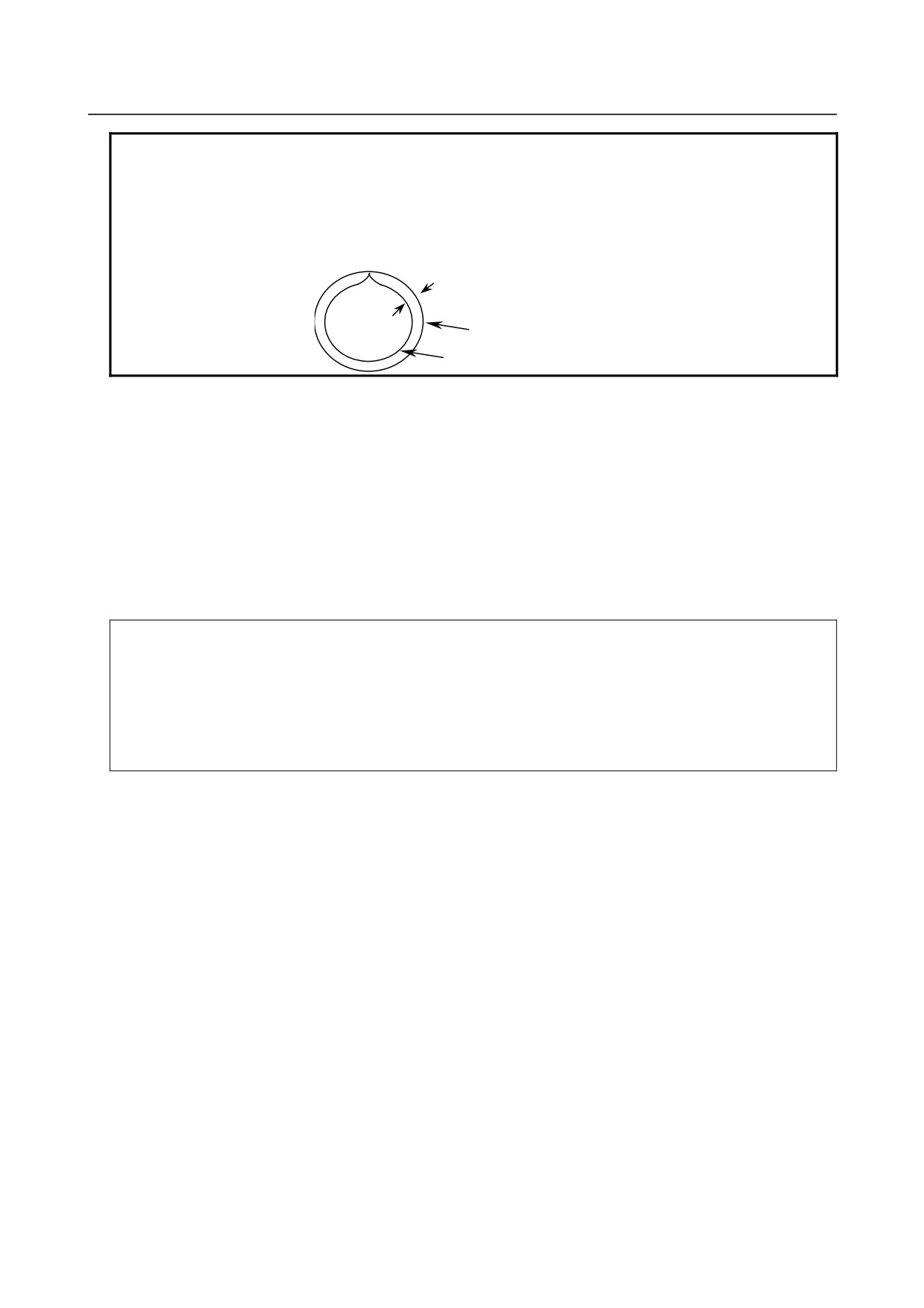
The radius of continuous circle motion is smaller than that specified at the start
of continuous circle motion, and is larger when continuous circle motion comes
to a deceleration stop. In the steady state, the radius is smaller than that
specified. This is an error that occurs due to acceleration/deceleration after
information and the delay of the servo system.
Error that occurs due to
acceleration/deceleration after
interpolation and the delay of the servo
system
Specified
Actual path
-
Mode in progress signal
This signal notifies the PMC that continuous circle motion-based groove cutting mode is in progress.
The signal is set to "1" if continuous circle motion-based groove cutting mode is turned on.
The signal is set to "0" if continuous circle motion-based groove cutting mode is canceled.
-
Clamping the feedrate with the acceleration of continuous circle motion
Using the I and K commands in G12.4/13.4 and the acceleration clamp value for continuous circle motion
(parameter No. 3490), the feedrate command F for continuous circle motion can be clamped.
Clamp feedrate F = SQR (parameter No.3490 × (I-K) / 2)× 60
Example If parameter No. 3490 = 100
If G13.4 P1 I10.0 K5.0 Q1.0 F1000 ;, clamp feedrate = 948. Thus, execution with
an F value of 948
If G13.4 P1 I10.0 K8.0 Q1.0 F1000 ;, clamp feedrate = 600. Thus, execution with
an F value of 600
If G13.4 P1 I10.0 K9.0 Q1.0 F1000 ;, clamp feedrate = 424. Thus, execution with
an F value of 424
A continuous circle motion feedrate override is applied to the clamped feedrate.
-
Acceleration deceleration after interpolation
In continuous circle motion-based groove cutting mode, acceleration/deceleration after interpolation is
enabled.
-
Selecting stoppage conditions
(1) Stoppage of continuous circle motion due to a feed hold, single block, etc.
It can be selected whether to continue or stop continuous circle motion when a specified operation is
stopped due to one of the various stoppage conditions such as a feed hold and a single block, using a
parameter:
Bit 4 (GCC) of parameter No. 3452 = 0 : Stops continuous circle motion.
Bit 4 (GCC) of parameter No. 3452 = 1 : Continues continuous circle motion.
(2) Stoppage condition/mode switching
The conditions for groove cutting path operation, continuous circle motion stoppage/continuation,
and switching to operation mode in connection with stoppage conditions are as given in Table 3.6
(a).
- 34 -

B-64484EN-2/02
PROGRAMMING
3.INTERPOLATION FUNCTION
Table 3.6 (a)
Continuous circle motion
Groove cutting
stoppage/continuation
Switching to operation
Stoppage condition
path operation
Stoppage
Continuation
mode
(GCC = 0)
(GCC = 1)
Feed hold
Deceleration stop
Deceleration stop
Continuation
Possible after the stoppage
of path operation
Single block
Deceleration stop
Deceleration stop
Continuation
Possible after the stoppage
of path operation
Switching to manual
Deceleration stop
Deceleration stop
Continuation
To be performed after the
mode
stoppage of path operation
Switching between
Deceleration stop
Deceleration stop
Continuation
Possible after the stoppage
auto modes
of path operation
MDI operation
Deceleration stop
Deceleration stop
Continuation
Possible after the stoppage
of path operation
Pitch override of 0%
Deceleration stop
Deceleration stop
Continuation
Possible after the stoppage
of path operation
M/S/T code FIN
Deceleration stop
Deceleration stop
Continuation
Possible after the stoppage
awaiting
of path operation
Programming error
Deceleration stop
Deceleration stop
Continuation
Possible after the stoppage
of path operation
Overheat alarm
Deceleration stop
Deceleration stop
Continuation
Possible after the stoppage
of path operation
BG edit alarm
Continuation
Continuation
Continuation
Automatic operation does
not stop.
Mode end
Deceleration stop
Withdrawal by the
Withdrawal by the
Follows other stoppage
radius/
radius/
conditions.
deceleration stop
deceleration stop
Reset
Deceleration stop
Deceleration stop
Deceleration stop
Possible after the end of all
operations
Machine lock
*1
Deceleration stop
Deceleration stop
Deceleration stop
―――
Servo off
*1
Deceleration stop
Deceleration stop
Deceleration stop
―――
Interlock
*2
Deceleration stop
Deceleration stop
Deceleration stop
―――
OT alarm
Deceleration stop
Deceleration stop
Deceleration stop
Possible after the end of all
operations
DS alarm
Deceleration stop
Deceleration stop
Deceleration stop
Possible after the end of all
operations
Emergency stop
Immediate stop
Immediate stop
Immediate stop
Possible after an
emergency stop is
canceled
PC-related alarm
Immediate stop
Immediate stop
Immediate stop
Possible after an alarm is
canceled
Servo alarm
Immediate stop
Immediate stop
Immediate stop
Possible after an alarm is
canceled
Spindle alarm
Immediate stop
Immediate stop
Immediate stop
Possible after an alarm is
canceled
System alarm
Immediate stop
Immediate stop
Immediate stop
The power must be turned
off and then back on.
*1: Stoppage occurs only on the axis on which the function is enabled.
*2: Stoppage occurs on all axes if the function is enabled on at least one axis.
• If bit 4 (GCC) of parameter No. 3452 is 0, continuous circle motion stops due to the stoppage of axis
movement by the groove cutting path program, but because axis movement by the groove cutting
path program is independent of continuous circle motion, the stoppage will not exactly be at the
position of continuous circle motion converted from the groove cutting path program and the pitch.
- 35 -

3.INTERPOLATION FUNCTION
PROGRAMMING
B-64484EN-2/02
•
After the mode is switched to manual mode, the axes on which manual movement is possible do not
include the axes on which to perform continuous circle motion.
•
If continuous circle motion is to continue (bit 4 (GCC) of parameter No. 3452 = 1), there will be no
fluctuations in radius because continuous circle motion continues.
•
Movement to the continuous circle motion start position and movement to the groove cutting path
program end position after the end of continuous circle motion will stop under the stoppage
conditions below.
Reset
Deceleration stop
Machine lock
Deceleration stop
Servo off
Deceleration stop
Interlock
Deceleration stop
OT alarm
Deceleration stop
DS alarm
Deceleration stop
Emergency stop
Immediate stop
PC-related alarm
Immediate stop
Servo alarm
Immediate stop
Spindle alarm
Immediate stop
System alarm
Immediate stop
-
Feedrate specification and pitch override
(1)
Feedrate specification
For the feedrate during cutting, specify the feedrate for continuous circle motion.
This feedrate is displayed as a specified feedrate.
(2)
Continuous circle motion feedrate override
The feedrate override signals
(*FV0 to *FV7) are not effective to the specified feedrate for
continuous circle motion. Use the continuous circle motion feedrate override signals (*CGROV7 to
*CBROV0). If the continuous circle motion feedrate override is at 0%, continuous circle motion can
be stopped independently of the movement on the groove cutting path.
(3)
Feedrate override
The feedrate on the groove cutting path is determined with the pitch command. The feedrate
override signals (*FV0 to *FV7) are effective to the feedrate on the groove cutting path. This makes
it possible to change the feedrate for continuous circle motion independently of the feedrate on the
groove cutting path.
Also, the override cancel signal (OVC) and the second feedrate override signal (optional function)
are effective to the feedrate on the groove cutting path.
(4)
Dry run
The feedrate during a dry run is as given in Table 3.6 (b).
A dry run is not effective to the feedrate on the groove cutting path.
Table 3.6 (b)
Feedrate
Override
Feedrate on the groove
Feedrate F for continuous circle motion ×
Feedrate override
cutting path
pitch / 2πR
Manual rapid traverse selection signal (RT)
Feedrate for continuous
Dry run rate
0
1
circle motion
(Parameter No.1410)
JV
JVmax
JV :
Manual feedrate override
Jvmax :
Maximum manual feedrate override
- 36 -
B-64484EN-2/02
PROGRAMMING
3.INTERPOLATION FUNCTION
(5) Feedrate display
•
Specified feedrate display shows the specified speed for continuous circle motion.
•
Actual cutting feedrate display show the synthetic one from the feedrate for continuous circle
motion and the feedrate on the groove cutting path.
(6) Clamping with the maximum cutting feedrate
If the specification of the feedrate for continuous circle motion exceeds the maximum cutting
feedrate (parameter No. 1430), the specification of the feedrate for continuous circle motion is
clamped to calculate the feedrate on the groove cutting path. In addition, the feedrate for continuous
circle motion and the feedrate on the groove cutting path, to which their respective overrides have
been applied, are clamped with the maximum cutting feedrate.
Limitation
-
Mirror image
A mirror image is effective to groove cutting path commands only.
No mirror image is applied to continuous circle motion, movement to the continuous circle motion start
position, and movement to the groove cutting path program end position after the end of continuous circle
motion.
-
Distance to go
Movement to the continuous circle motion start position, movement of continuous circle motion, and
movement to the groove cutting path program end position after the end of continuous circle motion are
not reflected in the distance to go (on the position screen, etc.).
-
Workpiece coordinate system and machine coordinate system
Movement to the continuous circle motion start position, movement of continuous circle motion, and
movement to the groove cutting path program end position after the end of continuous circle motion are
not reflected in the workpiece coordinate system. The workpiece coordinate system is the coordinate
system of the groove cutting path program.
Note, however, that these movements are reflected in the machine coordinate system.
-
Axis moving signal
The axis moving signal does not change due to axis moving due to continuous circle motion.
Use the continuous circle motion-based groove cutting mode in progress signal.
-
Graphic display
The tool path of the program during cutting is in the workpiece coordinate system and, therefore, the
groove cutting command path is drawn.
-
Restart functions
The restart functions, such as program restart and tool retract and recover, cannot be used to start
continuous circle motion-based groove cutting in the middle of the groove cutting path program.
-
Retrace
Retrace cannot be used in continuous circle motion-based groove cutting mode.
-
AI contour control
In continuous circle motion-based groove cutting mode, AI contour control is disabled. If continuous
circle motion-based groove cutting is specified during AI contour control, AI contour control is
temporarily canceled. If continuous circle motion-based groove cutting mode is canceled, AI contour
control returns to on. Note that if AI contour control is disabled, acceleration/deceleration before
look-ahead interpolation, acceleration control, and optimum torque acceleration/deceleration are also
disabled.
- 37 -
3.INTERPOLATION FUNCTION
PROGRAMMING
B-64484EN-2/02
-
One-digit F code
The one-digit F code cannot be used in continuous circle motion-based groove cutting mode.
-
Interruption type custom macro
The interruption type custom macro cannot be used in continuous circle motion-based groove cutting
mode.
-
Commands that can be executed in continuous circle motion-based groove
cutting mode
The groove cutting path program can executed the following commands only:
• G01
• G02, G03 (except helical interpolation and helical interpolation B)
• G04
• G90, G91
• M/S/T (auxiliary function), Second auxiliary function
• G00 (An operation can be selected with bit 0 (GG0) of parameter No. 3452.
GG0 = 0: Alarm PS5256 is issued.
GG0 = 1: The G00 command is moved as G01 operation.)
• G94 (Feed per minute)
-
Modes in which the continuous circle motion-based groove cutting mode
command cannot be specified
The continuous circle motion-based groove cutting command cannot be executed in the function modes
below.
Interpolation function
•
Helical interpolation
•
Helical interpolation B
•
Conical interpolation / spiral interpolation
•
Polar coordinate interpolation
•
Cylindrical interpolation / Cutting point interpolation for cylindrical interpolation
•
Exponential interpolation
•
Smooth interpolation
•
Nano smoothing
•
NURBS interpolation
•
Hypothetical axis interpolation
•
Variable lead thread cutting
•
Circular thread cutting
•
3-dimensional circular interpolation
•
Involute interpolation
•
Thread cutting
Feed function
•
One-digit F code feed / feed per revolution / inverse time feed
•
Exact stop / Tapping mode / automatic corner override
Coordinate value and dimension
•
Polar coordinate command
Function to simplify programming
•
Figure copying
•
3-dimensional coordinate system conversion
•
Canned cycle for drilling
•
Rigid tapping
•
Index table indexing
- 38 -
B-64484EN-2/02
PROGRAMMING
3.INTERPOLATION FUNCTION
Compensation function
•
Scaling
•
Programmable mirror image
•
Tool offset
•
Tool radius compensation
•
Tool nose radius compensation/vector retention/corner circular interpolation
•
3-dimensional tool compensation
•
Coordinate system rotation
Axis control function
•
Polygon turning
•
Arbitrary angular axis control
5-axis machining function
•
Tool center point control for 5-axis machining
•
Tilted working plane command
•
Inclined Rotary Axis Control
•
3-dimensional cutter compensation
Multi-path control function
•
Inter-path waiting / Path spindle control
•
Synchronous/Composite/Superimposed control
- 39 -
3.INTERPOLATION FUNCTION
PROGRAMMING
B-64484EN-2/02
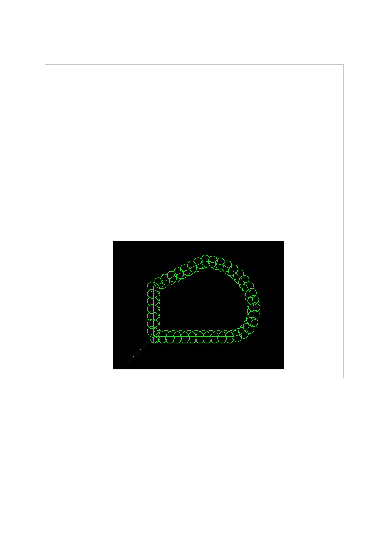
Example
If the following program is executed, the center of the tool moves as shown in
the figure below.
(This program is merely a sample. The Q and F commands must be determined
according to the cutting conditions.)
O0002 ;
N01 G90 G0 X0 Y0 Z0 ;
N02 G91 G00 X20.0 Y20.0 ;
N03 G01 Z-25.0 F5000 ;
N04 G13.4 P1 I20.0 K10.0 Q5.0 F3000 ;
N05 Y40.0 ;
N06 X40.0 Y20.0 ;
N07 G02 X40.0 Y-40.0 R40.0 ;
N08 X-20.0 Y-20.0 R20.0 ;
N09 G01 X-60. ;
N10 G13.4 P0 ;
N11 G00 Z25.0 ;
N12 X-20.0 Y-20.0 M02 ;
%
- 40 -
4.COORDINATE VALUE AND
B-64484EN-2/02
PROGRAMMING
DIMENSION
4 COORDINATE VALUE AND DIMENSION
Chapter 4, "COORDINATE VALUE AND DIMENSION", consists of the following sections:
4.1 POLAR COORDINATE COMMAND (G15, G16)
41
4.1
POLAR COORDINATE COMMAND (G15, G16)
The end point coordinate value can be input in polar coordinates (radius and angle).
The plus direction of the angle is counterclockwise of the selected plane first axis + direction, and the
minus direction is clockwise.
Both radius and angle can be commanded in either absolute or incremental programming (G90, G91).
Format
Gxx Gyy G16; Starting the polar coordinate command
(polar coordinate mode)
G00 IP_ ;
:
Polar coordinate command
:
G15;
Canceling the polar coordinate command
(polar coordinate mode)
G16 : Polar coordinate command
G15 : Polar coordinate command cancel
Gxx
: Plane selection of the polar coordinate command (G17, G18 or G19)
Gyy
: Center selection of the polar coordinate command (G90 or G91)
G90 specifies the origin of the workpiece coordinate system as the origin of the polar
coordinate system, from which a radius is measured.
G91 specifies the current position as the origin of the polar coordinate system, from
which a radius is measured.
IP_
: Specifying the addresses of axes constituting the plane selected for the polar
coordinate system, and their values
First axis : radius of polar coordinate
Second axis : angle of polar coordinate
-
Setting the origin of the workpiece coordinate system as the origin of the
polar coordinate system
Specify the radius (the distance between the origin and the point) to be programmed with an absolute
programming. The origin of the workpiece coordinate system is set as the origin of the polar coordinate
system.
When a local coordinate system (G52) is used, the origin of the local coordinate system becomes the
center of the polar coordinates.
Command position
Command position
Radius
Radius
Angle
Actual position
Angle
Actual position
When the angle is specified with an
When the angle is specified with an
absolute command
incremental command
- 41 -
4. COORDINATE VALUE AND
DIMENSION
PROGRAMMING
B-64484EN-2/02
-
Setting the current position as the origin of the polar coordinate system
Specify the radius (the distance between the current position and the point) to be programmed with an
incremental programming. The current position is set as the origin of the polar coordinate system.
Command position
Command position
Angle
Radius Angle
Radius
Actual position
Actual position
When the angle is specified with an
When the angle is specified with an
absolute command
incremental command
Example
Bolt hole circle
Y
- The origin of the workpiece coordinate
system is set as the origin of the polar
coordinate system.
- The XY plane is selected.
150°
30°
X
270°
100mm
-
Specifying angles and a radius with absolute programmings
N1 G17 G90 G16 ; Specifying the polar coordinate command and selecting the XY plane
Setting the origin of the workpiece coordinate system as the origin of the polar
coordinate system
N2 G81 X100.0 Y30.0 Z-20.0 R-5.0 F200.0 ;
Specifying a distance of 100 mm and an angle of 30 degrees
N3 Y150.0 ;
Specifying a distance of 100 mm and an angle of 150 degrees
N4 Y270.0 ;
Specifying a distance of 100 mm and an angle of 270 degrees
N5 G15 G80 ;
Canceling the polar coordinate command
-
Specifying angles with incremental programmings and a radius with absolute
programmings
N1 G17 G90 G16; Specifying the polar coordinate command and selecting the XY plane
Setting the origin of the workpiece coordinate system as the origin of the polar
coordinate system
N2 G81 X100.0 Y30.0 Z-20.0 R-5.0 F200.0 ;
Specifying a distance of 100 mm and an angle of 30 degrees
N3 G91 Y120.0 ; Specifying a distance of 100 mm and an angle of +120 degrees
N4 Y120.0 ;
Specifying a distance of 100 mm and an angle of +120 degrees
N5 G15 G80 ;
Canceling the polar coordinate command
Limitation
-
Specifying a radius in the polar coordinate mode
In the polar coordinate mode, specify a radius for circular interpolation or helical interpolation (G02,
G03) with R.
- 42 -
4.COORDINATE VALUE AND
B-64484EN-2/02
PROGRAMMING
DIMENSION
-
Axes that are not considered part of a polar coordinate command in the polar
coordinate mode
Axes specified for the following commands are not considered part of the polar coordinate command:
• Dwell (G04)
• Programmable data input (G10)
• Local coordinate system setting (G52)
• Workpiece coordinate system setting (G92)
• Machine coordinate system setting (G53)
• Stored stroke check (G22)
• Coordinate system rotation (G68)
• Scaling (G51)
-
Optional chamfering and corner R
Optional chamfering and corner R cannot be specified in polar coordinate mode.
- 43 -
5. FUNCTIONS TO SIMPLIFY
PROGRAMMING
PROGRAMMING
B-64484EN-2/02
5 FUNCTIONS TO SIMPLIFY PROGRAMMING
Chapter 5, "FUNCTIONS TO SIMPLIFY PROGRAMMING", consists of the following sections:
5.1 CANNED CYCLE FOR DRILLING
44
5.2 IN-POSITION CHECK SWITCHING FOR DRILLING CANNED CYCLES
75
5.3 RIGID TAPPING
89
5.4 OPTIONAL CHAMFERING AND CORNER R
103
5.5 INDEX TABLE INDEXING FUNCTION
106
5.6 IN-FEED CONTROL (FOR GRINDING MACHINE)
108
5.7 CANNED GRINDING CYCLE (FOR GRINDING MACHINE)
110
5.8 MULTIPLE REPETITIVE CYCLE (G70.7, G71.7, G72.7, G73.7, G74.7, G75.7,G76.7)
124
5.1
CANNED CYCLE FOR DRILLING
Overview
Canned cycles for drilling make it easier for the programmer to create programs. With a canned cycle, a
frequently-used machining operation can be specified in a single block with a G function; without canned
cycles, normally more than one block is required. In addition, the use of canned cycles can shorten the
program to save memory.
Table 5.1 (a) lists canned cycles for drilling.
Table 5.1 (a) Canned cycles for drilling
Drilling
Operation at the
Retraction
G code
Application
(-Z direction)
bottom of a hole
(+Z direction)
G73
Intermittent feed
-
Rapid traverse
High-speed peck drilling cycle
G74
Feed
Dwell → Spindle CW
Feed
Left-hand tapping cycle
G76
Feed
Spindle orientation
Rapid traverse
Fine boring cycle
G80
-
-
-
Cancel
Drilling cycle, spot drilling
G81
Feed
-
Rapid traverse
cycle
Drilling cycle, counter boring
G82
Feed
Dwell
Rapid traverse
cycle
G83
Intermittent feed
-
Rapid traverse
Peck drilling cycle
G84
Feed
Dwell → Spindle CCW
Feed
Tapping cycle
G85
Feed
-
Feed
Boring cycle
G86
Feed
Spindle stop
Rapid traverse
Boring cycle
G87
Feed
Spindle CW
Rapid traverse
Back boring cycle
G88
Feed
Dwell → Spindle stop
Manual
Boring cycle
G89
Feed
Dwell
Feed
Boring cycle
Explanation
A canned cycle for drilling consists of a sequence of six operations.
Operation 1 Positioning of axes X and Y (including also another axis)
Operation 2 Rapid traverse up to point R level
Operation 3 Hole machining
Operation 4 Operation at the bottom of a hole
Operation 5 Retraction to point R level
Operation 6 Rapid traverse up to the initial point
- 44 -
5.FUNCTIONS TO SIMPLIFY
B-64484EN-2/02
PROGRAMMING
PROGRAMMING
Operation 1
Initial level
Operation 2
Operation 6
Point R level
Operation 5
Operation 3
Rapid traverse
Operation 4
Feed
Fig. 5.1 (a) Operation sequence of canned cycle for drilling
-
Positioning plane
The positioning plane is determined by plane selection code G17, G18, or G19.
The positioning axis is an axis other than the drilling axis.
-
Drilling axis
Although canned cycles for drilling include tapping and boring cycles as well as drilling cycles, in this
chapter, only the term drilling will be used to refer to operations implemented with canned cycles.
The drilling axis is a basic axis (X, Y, or Z) not used to define the positioning plane, or any axis parallel
to that basic axis.
The axis (basic axis or parallel axis) used as the drilling axis is determined according to the axis address
for the drilling axis specified in the same block as G codes G73 to G89.
If no axis address is specified for the drilling axis, the basic axis is assumed to be the drilling axis.
Table 5.1 (b) Positioning plane and drilling axis
G code
Positioning plane
Drilling axis
G17
Xp-Yp plane
Zp
G18
Zp-Xp plane
Yp
G19
Yp-Zp plane
Xp
Xp: X axis or an axis parallel to the X axis
Yp: Y axis or an axis parallel to the Y axis
Zp: Z axis or an axis parallel to the Z axis
Example
Assume that the U, V and W axes be parallel to the X, Y, and Z axes respectively. This condition is
specified by parameter No. 1022.
G17 G81 Z_ _ :
The Z axis is used for drilling.
G17 G81 W_ _:
The W axis is used for drilling.
G18 G81 Y_ _ :
The Y axis is used for drilling.
G18 G81 V_ _ :
The V axis is used for drilling.
G19 G81 X_ _ :
The X axis is used for drilling.
G19 G81 U_ _ :
The U axis is used for drilling.
G17 to G19 may be specified in a block in which any of G73 to G89 is not specified.
- 45 -
5. FUNCTIONS TO SIMPLIFY
PROGRAMMING
PROGRAMMING
B-64484EN-2/02
CAUTION
Switch the drilling axis after canceling a canned cycle for drilling.
NOTE
A bit 0 (FXY) of parameter No. 5101 can be set to the Z axis always used as the
drilling axis. When FXY=0, the Z axis is always the drilling axis.
-
Travel distance along the drilling axis G90/G91
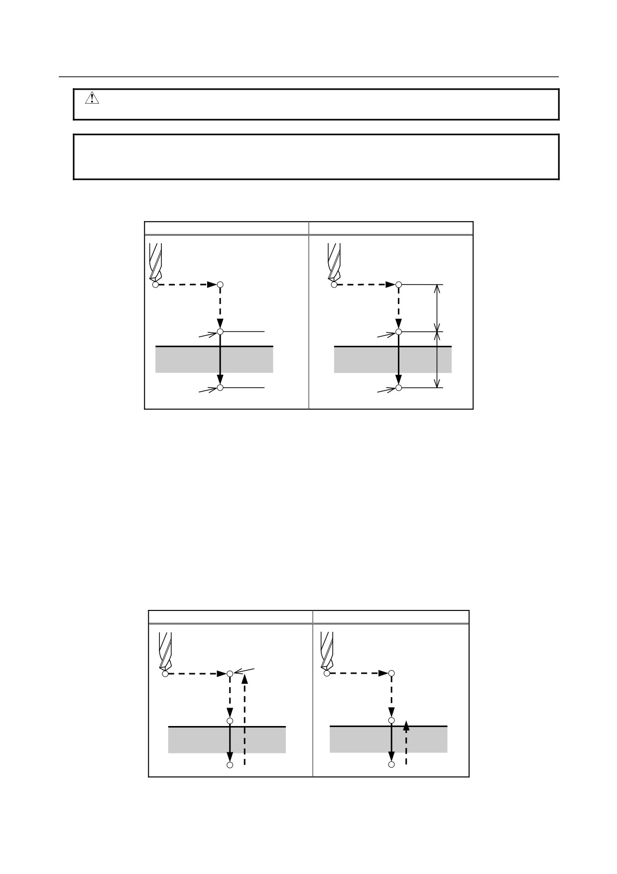
The travel distance along the drilling axis varies for G90 and G91 as Fig. 5.1 (b):
G90 (Absolute programming)
G91 (Incremental programming)
R
R
Point R
Point R
Z = 0
Z
Point Z
Z
Point Z
Fig. 5.1 (b) Absolute programming and incremental programming
-
Drilling mode
G73, G74, G76, and G81 to G89 are modal G codes and remain in effect until canceled. When in effect,
the current state is the drilling mode.
Once drilling data is specified in the drilling mode, the data is retained until modified or canceled.
Specify all necessary drilling data at the beginning of canned cycles; when canned cycles are being
performed, specify data modifications only.
-
Return point level G98/G99
When the tool reaches the bottom of a hole, the tool may be returned to point R or to the initial level.
These operations are specified with G98 and G99. The operations performed when G98 and G99 are
specified are shown in Fig. 5.1 (c). Generally, G99 is used for the first drilling operation and G98 is used
for the last drilling operation.
The initial level does not change even when drilling is performed in the G99 mode.
G98 (Return to initial level)
G99 (Return to point R level)
Initial level
Point R level
Fig. 5.1 (c) Initial level and point R level
- 46 -
5.FUNCTIONS TO SIMPLIFY
B-64484EN-2/02
PROGRAMMING
PROGRAMMING
-
Repeat
To repeat drilling for equally-spaced holes, specify the number of repeats in K_.
K is effective only within the block where it is specified.
Specify the first hole position in incremental programming (G91).
If it is specified in absolute programming (G90), drilling is repeated at the same position.
Number of repeats K
The maximum command value = 9999
If K0 is specified, drilling data is stored, but drilling is not performed.
NOTE
For K, specify an integer of 0 or 1 to 9999.
-
Single block
If a drilling cycle is performed in a single block, the control unit stops at each of the end points of
operations 1, 2, and 6 in Fig. 5.1 (a). This means that three starts are made to make a single hole. At the
end points of operations 1 and 2, the feed hold lamp turns on and the control unit stops. If the repetitive
count is not exhausted at the end point of operation 6, the control unit stops in the feed hold mode, and
otherwise, stops in the single block stop mode. Note that G87 does not cause a stop at point R in G87.
G88 causes a stop at point Z after a dwell.
-
Cancel
To cancel a canned cycle, use G80 or a group 01 G code.
Group 01 G codes
G00 : Positioning (rapid traverse)
G01 : Linear interpolation
G02 : Circular interpolation or helical interpolation (CW)
G03 : Circular interpolation or helical interpolation (CCW)
-
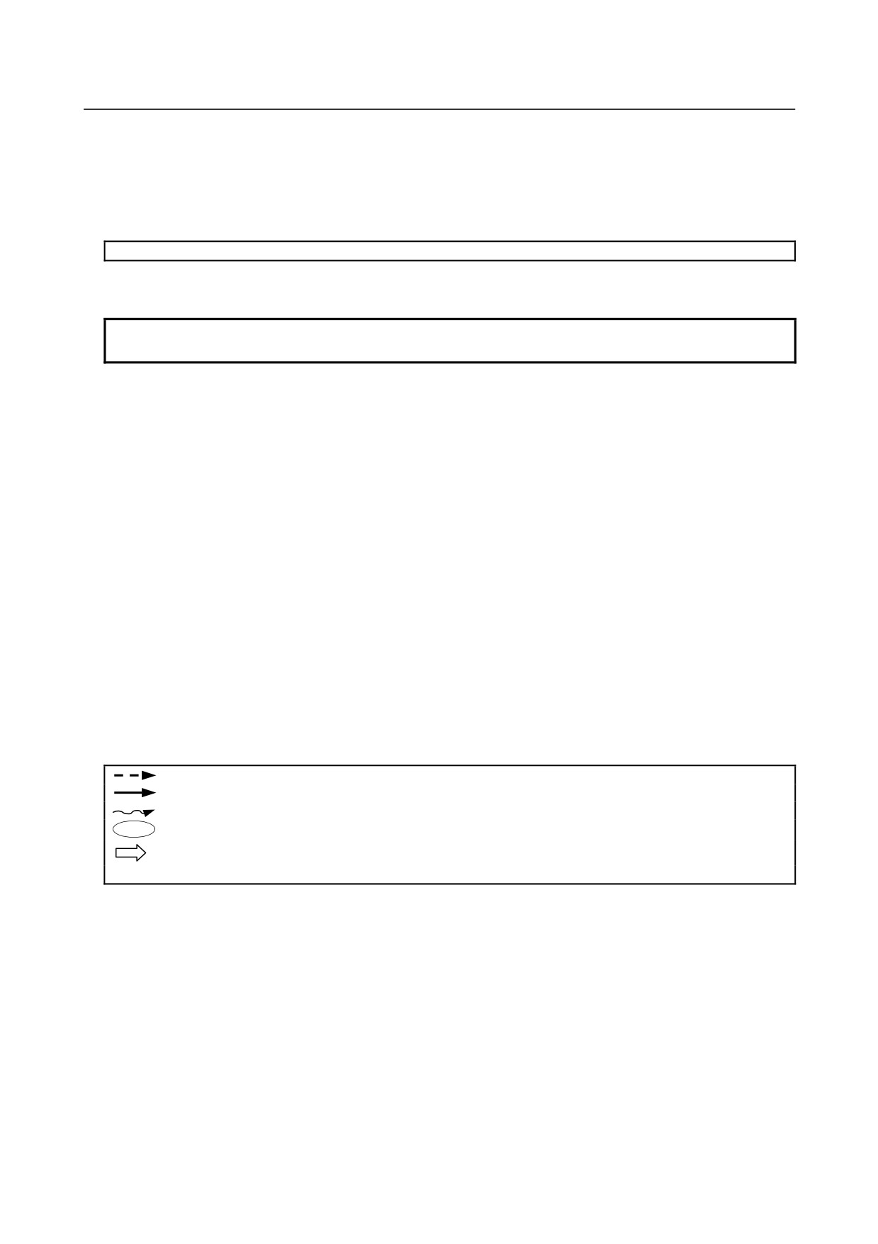
Symbols in figures
Subsequent sections explain the individual canned cycles. Figures in these Explanation use the following
symbols:
Positioning (rapid traverse G00)
Cutting feed (linear interpolation G01)
Manual feed
OSS
Oriented spindle stop (The spindle stops at a fixed rotation position)
Shift (rapid traverse G00)
P
Dwell
- 47 -
5. FUNCTIONS TO SIMPLIFY
PROGRAMMING
PROGRAMMING
B-64484EN-2/02
5.1.1
High-Speed Peck Drilling Cycle (G73)
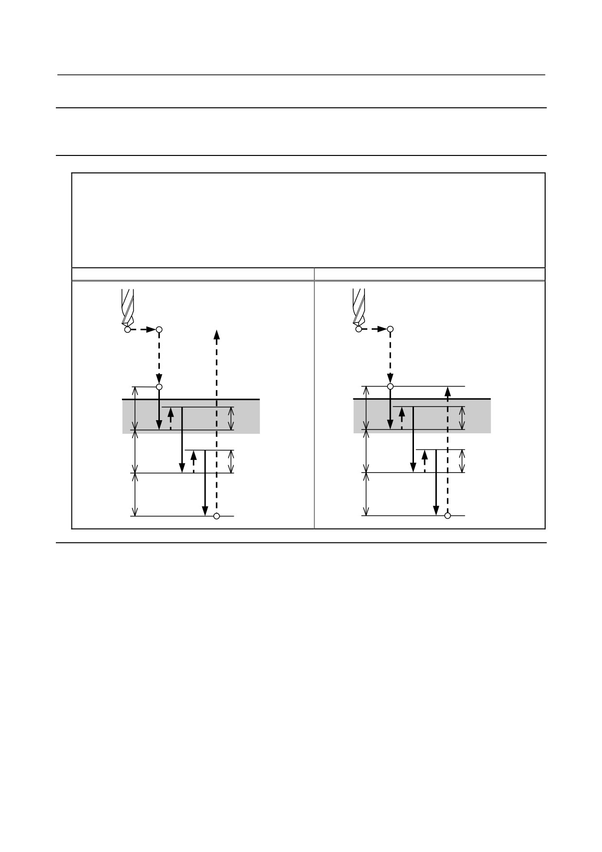
This cycle performs high-speed peck drilling. It performs intermittent cutting feed to the bottom of a hole
while removing chips from the hole.
Format
G73 X_ Y_ Z_ R_ Q_ F_ K_ ;
X_ Y_ : Hole position data
Z_
: The distance from point R to the bottom of the hole
R_
: The distance from the initial level to point R level
Q_
: Depth of cut for each cutting feed
F_
: Cutting feedrate
K_
: Number of repeats (if required)
G73 (G98)
G73 (G99)
Initial level
Point R
Point R
Point R level
q
q
d
d
q
q
d
d
q
q
Point Z
Point Z
Explanation
-
Operations
The high-speed peck drilling cycle performs intermittent feeding along the Z-axis. When this cycle is
used, chips can be removed from the hole easily, and a smaller value can be set for retraction. This allows,
drilling to be performed efficiently. Set the clearance, d, in parameter 5114.
The tool is retracted in rapid traverse.
-
Spindle rotation
Before specifying G73, rotate the spindle using an auxiliary function (M code).
-
Auxiliary function
When the G73 code and an M code are specified in the same block, the M code is executed at the time of
the first positioning operation. When K is used to specify the number of repeats, the M code is executed
for the first hole only; for the second and subsequent holes, the M code is not executed.
-
Tool length compensation
When a tool length compensation (G43, G44, or G49) is specified in the canned cycle for drilling, the
offset is applied after the time of positioning to point R.
- 48 -
5.FUNCTIONS TO SIMPLIFY
B-64484EN-2/02
PROGRAMMING
PROGRAMMING
Limitation
-
Axis switching
Before the drilling axis can be changed, the canned cycle for drilling must be canceled.
-
Drilling
In a block that does not contain X, Y, Z, R, or any other axes, drilling is not performed.
-
Q
Specify Q in blocks that perform drilling. If they are specified in a block that does not perform drilling,
they cannot be stored as modal data.
-
Cancel
Do not specify a G code of the 01 group (G00 to G03) and G73 in a single block. Otherwise, G73 will be
canceled.
-
Tool offset
In the canned cycle mode for drilling, tool offsets are ignored.
Example
M3 S2000 ;
Cause the spindle to start rotating.
G90 G99 G73 X300. Y-250. Z- 150. R-100. Q15. F120. ;
Position, drill hole 1, then return to point R.
Y-550. ;
Position, drill hole 2, then return to point R.
Y-750. ;
Position, drill hole 3, then return to point R.
X1000. ;
Position, drill hole 4, then return to point R.
Y-550. ;
Position, drill hole 5, then return to point R.
G98 Y-750. ;
Position, drill hole 6, then return to the initial level.
G80 G28 G91 X0 Y0 Z0 ; Return to the reference position
M5 ;
Cause the spindle to stop rotating.
- 49 -
5. FUNCTIONS TO SIMPLIFY
PROGRAMMING
PROGRAMMING
B-64484EN-2/02
5.1.2
Left-Handed Tapping Cycle (G74)
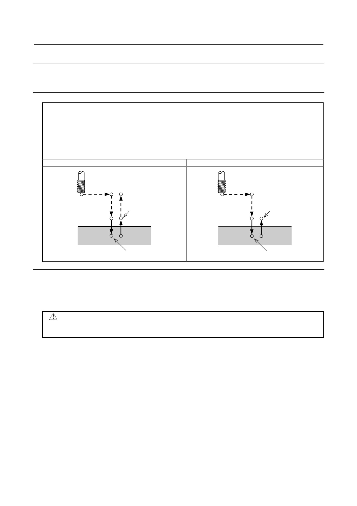
This cycle performs left-handed tapping. In the left-handed tapping cycle, when the bottom of the hole
has been reached, the spindle rotates clockwise.
Format
G74 X_ Y_ Z_ R_P_ F_ K_ ;
X_ Y_ : Hole position data
Z_
: The distance from point R to the bottom of the hole
R_
: The distance from the initial level to point R level
P_
: Dwell time
F_
: Cutting feedrate
K_
: Number of repeats (if required)
G74 (G98)
G74 (G99)
Initial level
Spindle
Spindle
CCW
CCW
P
Point R
P
Point R
Point R level
Point Z
Point Z
P
P
Spindle CW
Spindle CW
Explanation
-
Operations
Tapping is performed by turning the spindle counterclockwise. When the bottom of the hole has been
reached, the spindle is rotated clockwise for retraction. This creates a reverse thread.
CAUTION
Feedrate overrides are ignored during left-handed tapping. A feed hold does not
stop the machine until the return operation is completed.
-
Spindle rotation
Before specifying G74, use an auxiliary function (M code) to rotate the spindle counterclockwise.
If drilling is continuously performed with a small value specified for the distance between the hole
position and point R level or between the initial level and point R level, the normal spindle speed may not
be reached at the start of hole cutting operation. In this case, insert a dwell before each drilling operation
with G04 to delay the operation, without specifying the number of repeats for K. For some machines, the
above note may not be considered. Refer to the manual provided by the machine tool builder.
-
Auxiliary function
When the G74 command and an M code are specified in the same block, the M code is executed at the
time of the first positioning operation. When K is used to specify the number of repeats, the M code is
executed for the first hole only; for the second and subsequent holes, the M code is not executed.
-
Tool length compensation
When a tool length compensation (G43, G44, or G49) is specified in the canned cycle for drilling, the
offset is applied after the time of positioning to point R.
- 50 -
5.FUNCTIONS TO SIMPLIFY
B-64484EN-2/02
PROGRAMMING
PROGRAMMING
Limitation
-
Axis switching
Before the drilling axis can be changed, the canned cycle for drilling must be canceled.
-
Drilling
In a block that does not contain X, Y, Z, R, or any other axes, drilling is not performed.
-
P
Specify P in blocks that perform drilling. If it is specified in a block that does not perform drilling, it
cannot be stored as modal data.
-
Cancel
Do not specify a G code of the 01 group (G00 to G03) and G74 in a single block. Otherwise, G74 will be
canceled.
-
Tool offset
In the canned cycle mode for drilling, tool offsets are ignored.
Example
M4 S100 ;
Cause the spindle to start rotating.
G90 G99 G74 X300. Y-250. Z-150. R-120. F120. ; Position, tapping hole 1, then return to point R.
Y-550. ;
Position, tapping hole 2, then return to point R.
Y-750. ;
Position, tapping hole 3, then return to point R.
X1000. ;
Position, tapping hole 4, then return to point R.
Y-550. ;
Position, tapping hole 5, then return to point R.
G98 Y-750. ;
Position, tapping hole 6, then return to the initial
level.
G80 G28 G91 X0 Y0 Z0 ;
Return to the reference position
M5 ;
Cause the spindle to stop rotating.
- 51 -