FANUC Series 30i-MODEL B, 31i-MODEL B, 32i-MODEL B. For Machining Center System. OPERATOR'S MANUAL - page 1
B-64484EN-2/02
SAFETY PRECAUTIONS
SAFETY PRECAUTIONS
This section describes the safety precautions related to the use of CNC units.
It is essential that these precautions be observed by users to ensure the safe operation of machines
equipped with a CNC unit (all descriptions in this section assume this configuration). Note that some
precautions are related only to specific functions, and thus may not be applicable to certain CNC units.
Users must also observe the safety precautions related to the machine, as described in the relevant manual
supplied by the machine tool builder. Before attempting to operate the machine or create a program to
control the operation of the machine, the operator must become fully familiar with the contents of this
manual and relevant manual supplied by the machine tool builder.
CONTENTS
DEFINITION OF WARNING, CAUTION, AND NOTE
s-1
GENERAL WARNINGS AND CAUTIONS
s-2
WARNINGS AND CAUTIONS RELATED TO PROGRAMMING
s-3
WARNINGS AND CAUTIONS RELATED TO HANDLING
s-5
WARNINGS RELATED TO DAILY MAINTENANCE
s-7
DEFINITION OF WARNING, CAUTION, AND NOTE
This manual includes safety precautions for protecting the user and preventing damage to the machine.
Precautions are classified into Warning and Caution according to their bearing on safety. Also,
supplementary information is described as a Note. Read the Warning, Caution, and Note thoroughly
before attempting to use the machine.
WARNING
Applied when there is a danger of the user being injured or when there is a
danger of both the user being injured and the equipment being damaged if the
approved procedure is not observed.
CAUTION
Applied when there is a danger of the equipment being damaged, if the
approved procedure is not observed.
NOTE
The Note is used to indicate supplementary information other than Warning and
Caution.
• Read this manual carefully, and store it in a safe place.
s-1
SAFETY PRECAUTIONS
B-64484EN-2/02
GENERAL WARNINGS AND CAUTIONS
WARNING
1
Never attempt to machine a workpiece without first checking the operation of the
machine. Before starting a production run, ensure that the machine is operating
correctly by performing a trial run using, for example, the single block, feedrate
override, or machine lock function or by operating the machine with neither a tool
nor workpiece mounted. Failure to confirm the correct operation of the machine
may result in the machine behaving unexpectedly, possibly causing damage to
the workpiece and/or machine itself, or injury to the user.
2
Before operating the machine, thoroughly check the entered data.
Operating the machine with incorrectly specified data may result in the machine
behaving unexpectedly, possibly causing damage to the workpiece and/or
machine itself, or injury to the user.
3
Ensure that the specified feedrate is appropriate for the intended operation.
Generally, for each machine, there is a maximum allowable feedrate.
The appropriate feedrate varies with the intended operation. Refer to the manual
provided with the machine to determine the maximum allowable feedrate.
If a machine is run at other than the correct speed, it may behave unexpectedly,
possibly causing damage to the workpiece and/or machine itself, or injury to the
user.
4
When using a tool compensation function, thoroughly check the direction and
amount of compensation.
Operating the machine with incorrectly specified data may result in the machine
behaving unexpectedly, possibly causing damage to the workpiece and/or
machine itself, or injury to the user.
5
The parameters for the CNC and PMC are factory-set. Usually, there is not need
to change them. When, however, there is not alternative other than to change a
parameter, ensure that you fully understand the function of the parameter before
making any change.
Failure to set a parameter correctly may result in the machine behaving
unexpectedly, possibly causing damage to the workpiece and/or machine itself,
or injury to the user.
6
Immediately after switching on the power, do not touch any of the keys on the
MDI unit until the position display or alarm screen appears on the CNC unit.
Some of the keys on the MDI unit are dedicated to maintenance or other special
operations. Pressing any of these keys may place the CNC unit in other than its
normal state. Starting the machine in this state may cause it to behave
unexpectedly.
7
The OPERATOR’S MANUAL and programming manual supplied with a CNC
unit provide an overall description of the machine's functions, including any
optional functions. Note that the optional functions will vary from one machine
model to another. Therefore, some functions described in the manuals may not
actually be available for a particular model. Check the specification of the
machine if in doubt.
8
Some functions may have been implemented at the request of the machine-tool
builder. When using such functions, refer to the manual supplied by the
machine-tool builder for details of their use and any related cautions.
s-2
B-64484EN-2/02
SAFETY PRECAUTIONS
CAUTION
The liquid-crystal display is manufactured with very precise fabrication
technology. Some pixels may not be turned on or may remain on. This
phenomenon is a common attribute of LCDs and is not a defect.
NOTE
Programs, parameters, and macro variables are stored in nonvolatile memory in
the CNC unit. Usually, they are retained even if the power is turned off.
Such data may be deleted inadvertently, however, or it may prove necessary to
delete all data from nonvolatile memory as part of error recovery.
To guard against the occurrence of the above, and assure quick restoration of
deleted data, backup all vital data, and keep the backup copy in a safe place.
WARNINGS AND CAUTIONS RELATED TO PROGRAMMING
This section covers the major safety precautions related to programming. Before attempting to perform
programming, read the supplied OPERATOR’S MANUAL carefully such that you are fully familiar with
their contents.
WARNING
1
Coordinate system setting
If a coordinate system is established incorrectly, the machine may behave
unexpectedly as a result of the program issuing an otherwise valid move
command. Such an unexpected operation may damage the tool, the machine
itself, the workpiece, or cause injury to the user.
2
Positioning by nonlinear interpolation
When performing positioning by nonlinear interpolation (positioning by nonlinear
movement between the start and end points), the tool path must be carefully
confirmed before performing programming. Positioning involves rapid traverse. If
the tool collides with the workpiece, it may damage the tool, the machine itself,
the workpiece, or cause injury to the user.
3
Function involving a rotation axis
When programming polar coordinate interpolation or normal-direction
(perpendicular) control, pay careful attention to the speed of the rotation axis.
Incorrect programming may result in the rotation axis speed becoming
excessively high, such that centrifugal force causes the chuck to lose its grip on
the workpiece if the latter is not mounted securely. Such mishap is likely to
damage the tool, the machine itself, the workpiece, or cause injury to the user.
4
Inch/metric conversion
Switching between inch and metric inputs does not convert the measurement
units of data such as the workpiece origin offset, parameter, and current
position. Before starting the machine, therefore, determine which measurement
units are being used. Attempting to perform an operation with invalid data
specified may damage the tool, the machine itself, the workpiece, or cause injury
to the user.
s-3
SAFETY PRECAUTIONS
B-64484EN-2/02
WARNING
5
Constant surface speed control
When an axis subject to constant surface speed control approaches the origin of
the workpiece coordinate system, the spindle speed may become excessively
high. Therefore, it is necessary to specify a maximum allowable speed.
Specifying the maximum allowable speed incorrectly may damage the tool, the
machine itself, the workpiece, or cause injury to the user.
6
Stroke check
After switching on the power, perform a manual reference position return as
required. Stroke check is not possible before manual reference position return is
performed. Note that when stroke check is disabled, an alarm is not issued even
if a stroke limit is exceeded, possibly damaging the tool, the machine itself, the
workpiece, or causing injury to the user.
7
Tool post interference check
A tool post interference check is performed based on the tool data specified
during automatic operation. If the tool specification does not match the tool
actually being used, the interference check cannot be made correctly, possibly
damaging the tool or the machine itself, or causing injury to the user. After
switching on the power, or after selecting a tool post manually, always start
automatic operation and specify the tool number of the tool to be used.
8
Absolute/incremental mode
If a program created with absolute values is run in incremental mode, or vice
versa, the machine may behave unexpectedly.
9
Plane selection
If an incorrect plane is specified for circular interpolation, helical interpolation, or
a canned cycle, the machine may behave unexpectedly. Refer to the
descriptions of the respective functions for details.
10 Torque limit skip
Before attempting a torque limit skip, apply the torque limit. If a torque limit skip
is specified without the torque limit actually being applied, a move command will
be executed without performing a skip.
11 Programmable mirror image
Note that programmed operations vary considerably when a programmable
mirror image is enabled.
12 Compensation function
If a command based on the machine coordinate system or a reference position
return command is issued in compensation function mode, compensation is
temporarily canceled, resulting in the unexpected behavior of the machine.
Before issuing any of the above commands, therefore, always cancel
compensation function mode.
s-4
B-64484EN-2/02
SAFETY PRECAUTIONS
WARNINGS AND CAUTIONS RELATED TO HANDLING
This section presents safety precautions related to the handling of machine tools. Before attempting to
operate your machine, read the supplied OPERATOR’S MANUAL carefully, such that you are fully
familiar with their contents.
WARNING
1
Manual operation
When operating the machine manually, determine the current position of the tool
and workpiece, and ensure that the movement axis, direction, and feedrate have
been specified correctly. Incorrect operation of the machine may damage the
tool, the machine itself, the workpiece, or cause injury to the operator.
2
Manual reference position return
After switching on the power, perform manual reference position return as
required.
If the machine is operated without first performing manual reference position
return, it may behave unexpectedly. Stroke check is not possible before manual
reference position return is performed.
An unexpected operation of the machine may damage the tool, the machine
itself, the workpiece, or cause injury to the user.
3
Manual numeric command
When issuing a manual numeric command, determine the current position of the
tool and workpiece, and ensure that the movement axis, direction, and command
have been specified correctly, and that the entered values are valid.
Attempting to operate the machine with an invalid command specified may
damage the tool, the machine itself, the workpiece, or cause injury to the
operator.
4
Manual handle feed
In manual handle feed, rotating the handle with a large scale factor, such as 100,
applied causes the tool and table to move rapidly. Careless handling may
damage the tool and/or machine, or cause injury to the user.
5
Disabled override
If override is disabled (according to the specification in a macro variable) during
threading, rigid tapping, or other tapping, the speed cannot be predicted,
possibly damaging the tool, the machine itself, the workpiece, or causing injury
to the operator.
6
Origin/preset operation
Basically, never attempt an origin/preset operation when the machine is
operating under the control of a program. Otherwise, the machine may behave
unexpectedly, possibly damaging the tool, the machine itself, the tool, or causing
injury to the user.
7
Workpiece coordinate system shift
Manual intervention, machine lock, or mirror imaging may shift the workpiece
coordinate system. Before attempting to operate the machine under the control
of a program, confirm the coordinate system carefully.
If the machine is operated under the control of a program without making
allowances for any shift in the workpiece coordinate system, the machine may
behave unexpectedly, possibly damaging the tool, the machine itself, the
workpiece, or causing injury to the operator.
s-5
SAFETY PRECAUTIONS
B-64484EN-2/02
WARNING
8 Software operator's panel and menu switches
Using the software operator's panel and menu switches, in combination with the
MDI unit, it is possible to specify operations not supported by the machine
operator's panel, such as mode change, override value change, and jog feed
commands.
Note, however, that if the MDI unit keys are operated inadvertently, the machine
may behave unexpectedly, possibly damaging the tool, the machine itself, the
workpiece, or causing injury to the user.
9 RESET key
Pressing the RESET key stops the currently running program. As a result, the
servo axes are stopped. However, the RESET key may fail to function for
reasons such as an MDI unit problem. So, when the motors must be stopped,
use the emergency stop button instead of the RESET key to ensure security.
10 Manual intervention
If manual intervention is performed during programmed operation of the
machine, the tool path may vary when the machine is restarted. Before restarting
the machine after manual intervention, therefore, confirm the settings of the
manual absolute switches, parameters, and absolute/incremental command
mode.
11 Feed hold, override, and single block
The feed hold, feedrate override, and single block functions can be disabled
using custom macro system variable #3004. Be careful when operating the
machine in this case.
12 Dry run
Usually, a dry run is used to confirm the operation of the machine. During a dry
run, the machine operates at dry run speed, which differs from the
corresponding programmed feedrate. Note that the dry run speed may
sometimes be higher than the programmed feed rate.
13 Cutter and tool nose radius compensation in MDI mode
Pay careful attention to a tool path specified by a command in MDI mode,
because cutter or tool nose radius compensation is not applied. When a
command is entered from the MDI to interrupt in automatic operation in cutter or
tool nose radius compensation mode, pay particular attention to the tool path
when automatic operation is subsequently resumed. Refer to the descriptions of
the corresponding functions for details.
14 Program editing
If the machine is stopped, after which the machining program is edited
(modification, insertion, or deletion), the machine may behave unexpectedly if
machining is resumed under the control of that program. Basically, do not
modify, insert, or delete commands from a machining program while it is in use.
s-6
B-64484EN-2/02
SAFETY PRECAUTIONS
WARNINGS RELATED TO DAILY MAINTENANCE
WARNING
1 Memory backup battery replacement
When replacing the memory backup batteries, keep the power to the machine
(CNC) turned on, and apply an emergency stop to the machine. Because this
work is performed with the power on and the cabinet open, only those personnel
who have received approved safety and maintenance training may perform this
work.
When replacing the batteries, be careful not to touch the high-voltage circuits
(marked
and fitted with an insulating cover).
Touching the uncovered high-voltage circuits presents an extremely dangerous
electric shock hazard.
NOTE
The CNC uses batteries to preserve the contents of its memory, because it must
retain data such as programs, offsets, and parameters even while external
power is not applied.
If the battery voltage drops, a low battery voltage alarm is displayed on the
machine operator's panel or screen.
When a low battery voltage alarm is displayed, replace the batteries within a
week. Otherwise, the contents of the CNC's memory will be lost.
Refer to the Section “Method of replacing battery” in the OPERATOR’S
MANUAL (Common to Lathe System/Machining Center System) for details of
the battery replacement procedure.
WARNING
2 Absolute pulse coder battery replacement
When replacing the memory backup batteries, keep the power to the machine
(CNC) turned on, and apply an emergency stop to the machine. Because this
work is performed with the power on and the cabinet open, only those personnel
who have received approved safety and maintenance training may perform this
work.
When replacing the batteries, be careful not to touch the high-voltage circuits
(marked
and fitted with an insulating cover).
Touching the uncovered high-voltage circuits presents an extremely dangerous
electric shock hazard.
NOTE
The absolute pulse coder uses batteries to preserve its absolute position.
If the battery voltage drops, a low battery voltage alarm is displayed on the
machine operator's panel or screen.
When a low battery voltage alarm is displayed, replace the batteries within a
week. Otherwise, the absolute position data held by the pulse coder will be lost.
Refer to the FANUC SERVO MOTOR αi series Maintenance Manual for details
of the battery replacement procedure.
s-7
SAFETY PRECAUTIONS
B-64484EN-2/02
WARNING
3 Fuse replacement
Before replacing a blown fuse, however, it is necessary to locate and remove the
cause of the blown fuse.
For this reason, only those personnel who have received approved safety and
maintenance training may perform this work.
When replacing a fuse with the cabinet open, be careful not to touch the
high-voltage circuits (marked
and fitted with an insulating cover).
Touching an uncovered high-voltage circuit presents an extremely dangerous
electric shock hazard.
s-8
B-64484EN-2/02
TABLE OF CONTENTS
TABLE OF CONTENTS
SAFETY PRECAUTIONS
s-1
DEFINITION OF WARNING, CAUTION, AND NOTE
s-1
GENERAL WARNINGS AND CAUTIONS
s-2
WARNINGS AND CAUTIONS RELATED TO PROGRAMMING
s-3
WARNINGS AND CAUTIONS RELATED TO HANDLING
s-5
WARNINGS RELATED TO DAILY MAINTENANCE
s-7
I. GENERAL
1 GENERAL
3
1.1
NOTES ON READING THIS MANUAL
6
1.2
NOTES ON VARIOUS KINDS OF DATA
6
II. PROGRAMMING
1
GENERAL
9
1.1
TOOL FIGURE AND TOOL MOTION BY PROGRAM
9
2
PREPARATORY FUNCTION (G FUNCTION)
10
3
INTERPOLATION FUNCTION
15
3.1
INVOLUTE INTERPOLATION (G02.2, G03.2)
15
3.1.1
Automatic Speed Control for Involute Interpolation
19
3.1.2
Helical Involute Interpolation (G02.2, G03.2)
20
3.1.3
Involute Interpolation on Linear Axis and Rotary Axis
(G02.2, G03.2)
21
3.2
THREADING (G33)
23
3.3
CONTINUOUS THREADING
24
3.4
MULTIPLE THREADING
24
3.5
CIRCULAR THREAD CUTTING B (G2.1,G3.1)
26
3.6
GROOVE CUTTING BY CONTINUOUS CIRCLE MOTION (G12.4, G13.4)30
4
COORDINATE VALUE AND DIMENSION
41
4.1
POLAR COORDINATE COMMAND (G15, G16)
41
5
FUNCTIONS TO SIMPLIFY PROGRAMMING
44
5.1
CANNED CYCLE FOR DRILLING
44
5.1.1
High-Speed Peck Drilling Cycle (G73)
48
5.1.2
Left-Handed Tapping Cycle (G74)
50
5.1.3
Fine Boring Cycle (G76)
52
5.1.4
Drilling Cycle, Spot Drilling (G81)
54
5.1.5
Drilling Cycle Counter Boring Cycle (G82)
55
5.1.6
Peck Drilling Cycle (G83)
57
5.1.7
Small-Hole Peck Drilling Cycle (G83)
59
5.1.8
Tapping Cycle (G84)
63
5.1.9
Boring Cycle (G85)
65
5.1.10
Boring Cycle (G86)
66
5.1.11
Back Boring Cycle (G87)
68
c-1
TABLE OF CONTENTS
B-64484EN-2/02
5.1.12 Boring Cycle (G88)
70
5.1.13 Boring Cycle (G89)
72
5.1.14 Canned Cycle Cancel for Drilling (G80)
73
5.1.15 Example for Using Canned Cycles for Drilling
74
5.2
IN-POSITION CHECK SWITCHING FOR DRILLING CANNED CYCLE
75
5.3
RIGID TAPPING
89
5.3.1
Rigid Tapping (G84)
89
5.3.2
Left-Handed Rigid Tapping Cycle (G74)
93
5.3.3
Peck Rigid Tapping Cycle (G84 or G74)
97
5.3.4
Canned Cycle Cancel (G80)
100
5.3.5
Override during Rigid Tapping
100
5.3.5.1
Extraction override
100
5.3.5.2
Override signal
101
5.4
OPTIONAL CHAMFERING AND CORNER R
103
5.5
INDEX TABLE INDEXING FUNCTION
106
5.6
IN-FEED CONTROL (FOR GRINDING MACHINE)
108
5.7
CANNED GRINDING CYCLE (FOR GRINDING MACHINE)
110
5.7.1
Plunge Grinding Cycle (G75)
112
5.7.2
Direct Constant-Dimension Plunge Grinding Cycle (G77)
115
5.7.3
Continuous-feed Surface Grinding Cycle (G78)
118
5.7.4
Intermittent-feed Surface Grinding Cycle (G79)
121
5.8
MULTIPLE REPETITIVE CYCLE (G70.7, G71.7, G72.7, G73.7, G74.7,
G75.7,G76.7)
124
5.8.1
Stock Removal in Turning (G71.7)
125
5.8.2
Stock Removal in Facing (G72.7)
136
5.8.3
Pattern Repeating (G73.7)
140
5.8.4
Finishing Cycle (G70.7)
143
5.8.5
End Face Peck Drilling Cycle (G74.7)
147
5.8.6
Outer Diameter / Internal Diameter Drilling Cycle (G75.7)
149
5.8.7
Multiple Threading Cycle (G76.7)
151
5.8.8
Restrictions on Multiple Repetitive Cycle (G70.7, G71.7, G72.7, G73.7, G74.7,
G75.7, and G76.7)
156
6
COMPENSATION FUNCTION
158
6.1
TOOL LENGTH COMPENSATION SHIFT TYPES
158
6.2
AUTOMATIC TOOL LENGTH MEASUREMENT (G37)
165
6.3
TOOL OFFSET (G45 TO G48)
168
6.4
OVERVIEW OF CUTTER COMPENSATION (G40-G42)
173
6.5
OVERVIEW OF TOOL NOSE RADIUS COMPENSATION (G40-G42)
178
6.5.1
Imaginary Tool Nose
178
6.5.2
Direction of Imaginary Tool Nose
180
6.5.3
Offset Number and Offset Value
181
6.5.4
Workpiece Position and Move Command
181
6.5.5
Notes on Tool Nose Radius Compensation
186
6.6
DETAILS OF CUTTER OR TOOL NOSE RADIUS COMPENSATION
188
6.6.1
Overview
188
6.6.2
Tool Movement in Start-up
192
6.6.3
Tool Movement in Offset Mode
198
6.6.4
Tool Movement in Offset Mode Cancel
216
6.6.5
Prevention of Overcutting Due to Tool Radius / Tool Nose Radius
Compensation
222
6.6.6
Interference Check
225
c-2
B-64484EN-2/02
TABLE OF CONTENTS
6.6.6.1
Operation to be performed if an interference is judged to occur
228
6.6.6.2
Interference check alarm function
229
6.6.6.3
Interference check avoidance function
230
6.6.7
Tool Radius / Tool Nose Radius Compensation for Input from MDI
236
6.7
VECTOR RETENTION (G38)
238
6.8
CORNER CIRCULAR INTERPOLATION (G39)
239
6.9
3-DIMENSIONAL TOOL COMPENSATION (G40, G41)
241
6.10
TOOL COMPENSATION VALUES, NUMBER OF COMPENSATION
VALUES, AND ENTERING VALUES FROM THE PROGRAM (G10)
244
6.11
COORDINATE SYSTEM ROTATION (G68, G69)
247
6.12
GRINDING WHEEL WEAR COMPENSATION
254
6.13
ACTIVE OFFSET VALUE CHANGE FUNCTION BASED ON MANUAL
FEED
259
6.14
ROTARY TABLE DYNAMIC FIXTURE OFFSET
262
6.15
TOOL AXIS DIRECTION TOOL LENGTH COMPENSATION
268
6.15.1 Control Point Compensation of Tool Length Compensation Along Tool Axis...272
6.16
SPINDLE UNIT COMPENSATION, NUTATING ROTARY HEAD TOOL
LENGTH COMPENSATION
276
7
MEMORY OPERATION USING Series 15 PROGRAM FORMAT
280
7.1
MULTIPLE REPETITIVE CYCLE
281
7.1.1
Stock Removal in Turning (G71.7)
282
7.1.2
Stock Removal in Facing (G72.7)
294
7.1.3
Pattern Repeating (G73.7)
298
7.1.4
Finishing Cycle (G70.7)
301
7.1.5
End Face Peck Drilling Cycle (G74.7)
305
7.1.6
Outer Diameter / Internal Diameter Drilling Cycle (G75.7)
306
7.1.7
Multiple Threading Cycle (G76.7)
308
7.1.8
Restrictions on Multiple Repetitive Cycle
313
8
AXIS CONTROL FUNCTIONS
315
8.1
CHOPPING FUNCTION
315
8.2
CHOPPING FUNCTION BY FLEXIBLE SYNCHRONOUS CONTROL
321
8.3
PARALLEL AXIS CONTROL
323
9
GAS CUTTING MACHINE
328
9.1
TOOL OFFSET B
328
9.2
CONER CONTROL BY FEED RATE
331
9.3
AUTOMATIC EXACT STOP CHECK
333
9.4
AXIS SWITCHING
336
9.5
GENTLE CURVE CUTTING
339
9.6
GENTLE NORMAL DIRECTION CONTROL
341
9.6.1
Linear Distance Setting
342
III. OPERATION
1 SETTING AND DISPLAYING DATA
347
1.1
SCREENS DISPLAYED BY FUNCTION KEY
...................................347
1.1.1
Setting and Displaying the Tool Compensation Value
347
1.1.2
Tool Length Measurement
352
c-3
TABLE OF CONTENTS
B-64484EN-2/02
1.1.3
Tool Length/Workpiece Origin Measurement
355
1.1.4
Setting and Displaying the Rotary Table Dynamic Fixture Offset
374
1.1.5
Input of Tool Offset Value Measured B
377
1.1.6
Spindle Unit Compensation, Nutating Rotary Head Tool Length Compensation377
APPENDIX
A PARAMETERS
383
A.1
DESCRIPTION OF PARAMETERS
383
A.2
DATA TYPE
432
A.3
STANDARD PARAMETER SETTING TABLES
433
c-4

B-64484EN-2/02
GENERAL
1.GENERAL
1 GENERAL
This manual consists of the following parts:
About this manual
I.
GENERAL
Describes chapter organization, applicable models, related manuals, and notes for reading this
manual.
II.
PROGRAMMING
Describes each function: Format used to program functions in the NC language, characteristics, and
restrictions.
III. OPERATION
Describes the manual operation and automatic operation of a machine, procedures for inputting and
outputting data, and procedures for editing a program.
APPENDIX
Lists parameters.
NOTE
1 This manual describes the functions that can operate in the machining center
system path control type. For other functions not specific to the lathe system,
refer to the Operator's Manual (Common to Lathe System/Machining Center
System) (B-64484EN).
2 Some functions described in this manual may not be applied to some products.
For detail, refer to the DESCRIPTIONS manual (B-64482EN).
3 This manual does not detail the parameters not mentioned in the text. For
details of those parameters, refer to the Parameter Manual (B-64490EN).
Parameters are used to set functions and operating conditions of a CNC
machine tool, and frequently-used values in advance. Usually, the machine tool
builder factory-sets parameters so that the user can use the machine tool easily.
4 This manual describes not only basic functions but also optional functions. Look
up the options incorporated into your system in the manual written by the
machine tool builder.
Applicable models
This manual describes the models indicated in the table below.
In the text, the abbreviations indicated below may be used.
Model name
Abbreviation
FANUC Series 30i-B
30i -B
Series 30i
FANUC Series 31i-B
31i -B
Series 31i
FANUC Series 31i-B5
31i -B5
FANUC Series 32i-B
32i -B
Series 32i
NOTE
1 Unless otherwise noted, the model names 31i-B, 31i-B5, and 32i-B are
collectively referred to as 30i. However, this convention is not necessarily
observed when item 3 below is applicable.
2 Some functions described in this manual may not be applied to some products.
For details, refer to the Descriptions (B-64482EN).
- 3 -

1.GENERAL
GENERAL
B-64484EN-2/02
Special symbols
This manual uses the following symbols:
-
IP
Indicates a combination of axes such as X_ Y_ Z_
In the underlined position following each address, a numeric value such as a coordinate value is
placed (used in PROGRAMMING.).
-
;
Indicates the end of a block. It actually corresponds to the ISO code LF or EIA code CR.
Related manuals of
Series 30i- MODEL B
Series 31i- MODEL B
Series 32i- MODEL B
The following table lists the manuals related to Series 30i-B, Series 31i-B, Series 32i-B. This manual is
indicated by an asterisk(*).
Table 1 Related manuals
Manual name
Specification number
DESCRIPTIONS
B-64482EN
CONNECTION MANUAL (HARDWARE)
B-64483EN
CONNECTION MANUAL (FUNCTION)
B-64483EN-1
OPERATOR’S MANUAL (Common to Lathe System/Machining Center System)
B-64484EN
OPERATOR’S MANUAL (For Lathe System)
B-64484EN-1
OPERATOR’S MANUAL (For Machining Center System)
B-64484EN-2
*
MAINTENANCE MANUAL
B-64485EN
PARAMETER MANUAL
B-64490EN
Programming
Macro Executor PROGRAMMING MANUAL
B-63943EN-2
Macro Compiler PROGRAMMING MANUAL
B-66263EN
C Language Executor PROGRAMMING MANUAL
B-63943EN-3
PMC
PMC PROGRAMMING MANUAL
B-64513EN
Network
PROFIBUS-DP Board CONNECTION MANUAL
B-63993EN
Fast Ethernet / Fast Data Server OPERATOR’S MANUAL
B-64014EN
DeviceNet Board CONNECTION MANUAL
B-64043EN
FL-net Board CONNECTION MANUAL
B-64163EN
CC-Link Board CONNECTION MANUAL
B-64463EN
Operation guidance function
MANUAL GUIDE i (Common to Lathe System/Machining Center System)
B-63874EN
OPERATOR’S MANUAL
MANUAL GUIDE i (For Machining Center System) OPERATOR’S MANUAL
B-63874EN-2
MANUAL GUIDE i (Set-up Guidance Functions) OPERATOR’S MANUAL
B-63874EN-1
Dual Check Safety
Dual Check Safety CONNECTION MANUAL
B-64483EN-2
- 4 -

B-64484EN-2/02
GENERAL
1.GENERAL
Related manuals of SERVO MOTOR αi/βi series
The following table lists the manuals related to SERVO MOTOR αi/βi series
Table 2 Related manuals
Manual name
Specification number
FANUC AC SERVO MOTOR αi series DESCRIPTIONS
B-65262EN
FANUC AC SPINDLE MOTOR αi series DESCRIPTIONS
B-65272EN
FANUC AC SERVO MOTOR βi series DESCRIPTIONS
B-65302EN
FANUC AC SPINDLE MOTOR βi series DESCRIPTIONS
B-65312EN
FANUC SERVO AMPLIFIER αi series DESCRIPTIONS
B-65282EN
FANUC SERVO AMPLIFIER βi series DESCRIPTIONS
B-65322EN
FANUC SERVO MOTOR αis series
FANUC SERVO MOTOR αi series
FANUC AC SPINDLE MOTOR αi series
B-65285EN
FANUC SERVO AMPLIFIER αi series
MAINTENANCE MANUAL
FANUC SERVO MOTOR βis series
FANUC AC SPINDLE MOTOR βi series
B-65325EN
FANUC SERVO AMPLIFIER βi series
MAINTENANCE MANUAL
FANUC AC SERVO MOTOR αi series
FANUC AC SERVO MOTOR βi series
FANUC LINEAR MOTOR LiS series
B-65270EN
FANUC SYNCHRONOUS BUILT-IN SERVO MOTOR DiS series
PARAMETER MANUAL
FANUC AC SPINDLE MOTOR αi/βi series,
BUILT-IN SPINDLE MOTOR Bi series
B-65280EN
PARAMETER MANUAL
The above servo motors and the corresponding spindles can be connected to the CNC covered in this
manual. In the αi SV, αi SP, αi PS, and βi SV series, however, they can be connected only to 30
i-B-compatible versions. In the βi SVSP series, they cannot be connected.
This manual mainly assumes that the FANUC SERVO MOTOR αi series of servo motor is used. For
servo motor and spindle information, refer to the manuals for the servo motor and spindle that are actually
connected.
- 5 -
1.GENERAL
GENERAL
B-64484EN-2/02
1.1
NOTES ON READING THIS MANUAL
CAUTION
1 The function of an CNC machine tool system depends not only on the CNC, but on
the combination of the machine tool, its magnetic cabinet, the servo system, the
CNC, the operator's panels, etc. It is too difficult to describe the function,
programming, and operation relating to all combinations. This manual generally
describes these from the stand-point of the CNC. So, for details on a particular
CNC machine tool, refer to the manual issued by the machine tool builder, which
should take precedence over this manual.
2 In the header field of each page of this manual, a chapter title is indicated so that
the reader can reference necessary information easily.
By finding a desired title first, the reader can reference necessary parts only.
3 This manual describes as many reasonable variations in equipment usage as
possible. It cannot address every combination of features, options and commands
that should not be attempted.
If a particular combination of operations is not described, it should not be
attempted.
1.2
NOTES ON VARIOUS KINDS OF DATA
CAUTION
Machining programs, parameters, offset data, etc. are stored in the CNC unit
internal non-volatile memory. In general, these contents are not lost by the
switching ON/OFF of the power. However, it is possible that a state can occur
where precious data stored in the non-volatile memory has to be deleted,
because of deletions from a maloperation, or by a failure restoration. In order to
restore rapidly when this kind of mishap occurs, it is recommended that you
create a copy of the various kinds of data beforehand.
- 6 -
B-64484EN-2/02
PROGRAMMING
1.GENERAL
1 GENERAL
Chapter 1, "GENERAL", consists of the following sections:
1.1 TOOL FIGURE AND TOOL MOTION BY PROGRAM
9
1.1
TOOL FIGURE AND TOOL MOTION BY PROGRAM
Explanation
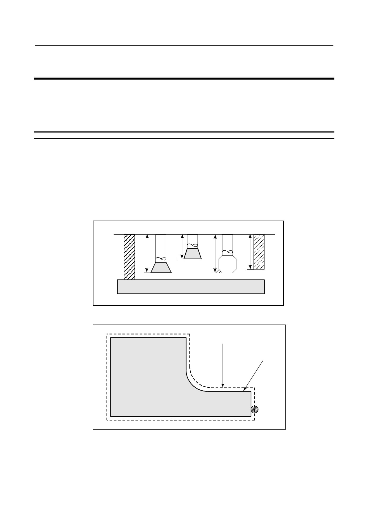
-
Machining using the end of cutter - Tool length compensation function
Usually, several tools are used for machining one workpiece. The tools have different tool length. It is
very troublesome to change the program in accordance with the tools.
Therefore, the length of each tool used should be measured in advance. By setting the difference between
the length of the standard tool and the length of each tool in the CNC (See Chapter, “Setting and
Displaying Data” in OPERATOR’S MANUAL (Common to Lathe System / Machining Center System)),
machining can be performed without altering the program even when the tool is changed. This function is
called tool length compensation (See Section, “Tool Length Compensation” in OPERATOR’S MANUAL
(Common to Lathe System / Machining Center System)).
H1
H2
H3
H4
Standard
tool
Workpiece
-
Machining using the side of cutter - Cutter compensation function
Cutter path using cutter compensation
Machined part figure
Workpiece
Tool
Because a cutter has a radius, the center of the cutter path goes around the workpiece with the cutter
radius deviated.
If radius of cutters are stored in the CNC (See Chapter, “Setting and Displaying Data” in OPERATOR’S
MANUAL (Common to Lathe System / Machining Center System)), the tool can be moved by cutter
radius apart from the machining part figure. This function is called cutter compensation (See Chapter,
“Compensation Function”).
- 9 -

2. PREPARATORY FUNCTION
(G FUNCTION)
PROGRAMMING
B-64484EN-2/02
2 PREPARATORY FUNCTION
(G FUNCTION)
A number following address G determines the meaning of the command for the concerned block.
G codes are divided into the following two types.
Type
Meaning
One-shot G code
The G code is effective only in the block in which it is specified.
Modal G code
The G code is effective until another G code of the same group is specified.
(Example)
G01 and G00 are modal G codes in group 01.
G01
X_ ;
Z_ ;
G01 is effective in this range.
X_ ;
G00
Z_ ;
G00 is effective in this range.
X_ ;
G01
X_ ;
:
Explanation
1.
When the clear state (bit 6 (CLR) of parameter No. 3402) is set at power-up or reset, the modal G
codes are placed in the states described below.
(1) The modal G codes are placed in the states marked with
as indicated in Table 2 (a).
(2) G20 and G21 remain unchanged when the clear state is set at power-up or reset.
(3) Which status G22 or G23 at power on is set by bit 7 (G23) of parameter No. 3402. However,
G22 and G23 remain unchanged when the clear state is set at reset.
(4) The user can select G00 or G01 by setting bit 0 (G01) of parameter No. 3402.
(5) The user can select G90 or G91 by setting bit 3 (G91) of parameter No. 3402.
When G code system B or C is used in the lathe system, setting bit 3 (G91) of parameter No.
3402 determines which code, either G90 or G91, is effective.
(6) In the machining center system, the user can select G17, G18, or G19 by setting bits 1 (G18)
and 2 (G19) of parameter No. 3402.
2.
G codes other than G10 and G11 are one-shot G codes.
3.
When a G code not listed in the G code list is specified, or a G code that has no corresponding
option is specified, alarm PS0010 occurs.
4.
Multiple G codes can be specified in the same block if each G code belongs to a different group. If
multiple G codes that belong to the same group are specified in the same block, only the last G code
specified is valid.
5.
If a G code belonging to group 01 is specified in a canned cycle for drilling, the canned cycle for
drilling is cancelled. This means that the same state set by specifying G80 is set. Note that the G
codes in group 01 are not affected by a G code specifying a canned cycle for drilling.
6.
G codes are indicated by group.
7.
The group of G60 is switched according to the setting of the bit 0 (MDL) of parameter No. 5431.
(When the MDL bit is set to 0, the 00 group is selected. When the MDL bit is set to 1, the 01 group
is selected.)
- 10 -

2.PREPARATORY FUNCTION
B-64484EN-2/02
PROGRAMMING
(G FUNCTION)
Table 2 (a) G code list
G code
Group
Function
G00
Positioning (rapid traverse)
G01
Linear interpolation (cutting feed)
G02
Circular interpolation CW or helical interpolation CW
G03
Circular interpolation CCW or helical interpolation CCW
01
G02.1, G03.1
Circular thread cutting B CW/CCW
G02.2, G03.2
Involute interpolation CW/CCW
G02.3, G03.3
Exponential interpolation CW/CCW
G02.4, G03.4
3-dimensional coordinate system conversion CW/CCW
G04
Dwell
AI contour control (high-precision contour control compatible command),
G05
00
High-speed cycle machining, High-speed binary program operation
G05.1
AI contour control / Nano smoothing / Smooth interpolation
G05.4
HRV3, 4 on/off
G06.2
01
NURBS interpolation
G07
Hypothetical axis interpolation
G07.1 (G107)
Cylindrical interpolation
G08
AI contour control (advanced preview control compatible command)
G09
Exact stop
00
G10
Programmable data input
G10.6
Tool retract and recover
G10.9
Programmable switching of diameter/radius specification
G11
Programmable data input mode cancel
G12.1
Polar coordinate interpolation mode
21
G13.1
Polar coordinate interpolation cancel mode
G12.4
Groove cutting by continuous circle motion (CW)
00
G13.4
Groove cutting by continuous circle motion (CCW)
G15
Polar coordinates command cancel
17
G16
Polar coordinates command
G17
XpYp plane selection
Xp: X axis or its parallel axis
G17.1
Plane conversion function
Yp: Y axis or its parallel axis
02
G18
ZpXp plane selection
Zp: Z axis or its parallel axis
G19
YpZp plane selection
G20 (G70)
Input in inch
06
G21 (G71)
Input in mm
G22
Stored stroke check function on
04
G23
Stored stroke check function off
G25
Spindle speed fluctuation detection off
19
G26
Spindle speed fluctuation detection on
G27
Reference position return check
G28
Automatic return to reference position
G28.2
In-position check disable reference position return
G29
Movement from reference position
G30
00
2nd, 3rd and 4th reference position return
G30.1
Floating reference position return
G30.2
In-position check disable 2nd, 3rd, or 4th reference position return
G31
Skip function
G31.8
EGB-axis skip
G33
Threading
G34
Variable lead threading
01
G35
Circular threading CW
G36
Circular threading CCW
- 11 -

2. PREPARATORY FUNCTION
(G FUNCTION)
PROGRAMMING
B-64484EN-2/02
Table 2 (a) G code list
G code
Group
Function
G37
Automatic tool length measurement
G38
00
Tool radius/tool nose radius compensation : preserve vector
G39
Tool radius/tool nose radius compensation : corner circular interpolation
G40
Tool radius/tool nose radius compensation : cancel
3-dimensional cutter compensation : cancel
Tool radius/tool nose radius compensation : left
G41
3-dimensional cutter compensation : left
Tool radius/tool nose radius compensation : right
G42
3-dimensional cutter compensation : right
G41.2
3-dimensional cutter compensation : left (type 1)
G41.3
07
3-dimensional cutter compensation : leading edge offset
G41.4
3-dimensional cutter compensation : left (type 1) (FS16i-compatible command)
G41.5
3-dimensional cutter compensation : left (type 1) (FS16i-compatible command)
G41.6
3-dimensional cutter compensation : left (type 2)
G42.2
3-dimensional cutter compensation : right (type 1)
G42.4
3-dimensional cutter compensation : right (type 1) (FS16i-compatible command)
G42.5
3-dimensional cutter compensation : right (type 1) (FS16i-compatible command)
G42.6
3-dimensional cutter compensation : right (type 2)
G40.1
Normal direction control cancel mode
G41.1
18
Normal direction control on : left
G42.1
Normal direction control on : right
G43
Tool length compensation +
G44
Tool length compensation -
G43.1
Tool length compensation in tool axis direction
08
G43.3
Nutating rotary head tool length compensation
G43.4
Tool center point control (type 1)
G43.5
Tool center point control (type 2)
G45
Tool offset : increase
G46
Tool offset : decrease
00
G47
Tool offset : double increase
G48
Tool offset : double decrease
G49 (G49.1)
08
Tool length compensation cancel
G44.9
Spindle unit compensation
27
G49.9
Spindle unit compensation cancel
G50
Scaling cancel
11
G51
Scaling
G50.1
Programmable mirror image cancel
22
G51.1
Programmable mirror image
G50.2
Polygon turning cancel
31
G51.2
Polygon turning
G50.4
Cancel synchronous control
G50.5
Cancel composite control
G50.6
Cancel superimposed control
G51.4
Start synchronous control
G51.5
Start composite control
00
G51.6
Start superimposed control
G52
Local coordinate system setting
G53
Machine coordinate system setting
G53.1
Tool axis direction control
G53.6
Tool center point retention type tool axis direction control
- 12 -

2.PREPARATORY FUNCTION
B-64484EN-2/02
PROGRAMMING
(G FUNCTION)
Table 2 (a) G code list
G code
Group
Function
G54 (G54.1)
Workpiece coordinate system 1 selection
G55
Workpiece coordinate system 2 selection
G56
Workpiece coordinate system 3 selection
14
G57
Workpiece coordinate system 4 selection
G58
Workpiece coordinate system 5 selection
G59
Workpiece coordinate system 6 selection
G54.2
23
Rotary table dynamic fixture offset
G54.4
33
Workpiece setting error compensation
G60
00
Single direction positioning
G61
Exact stop mode
G62
Automatic corner override
15
G63
Tapping mode
G64
Cutting mode
G65
00
Macro call
G66
Macro modal call A
G66.1
12
Macro modal call B
G67
Macro modal call A/B cancel
G68
Coordinate system rotation start or 3-dimensional coordinate conversion mode on
G69
Coordinate system rotation cancel or 3-dimensional coordinate conversion mode off
G68.2
16
Tilted working plane command
G68.3
Tilted working plane command by tool axis direction
G68.4
Tilted working plane command (incremental multi-command)
G70.7
Finishing cycle
G71.7
Outer surface rough machining cycle
G72.7
End rough machining cycle
G73.7
Closed loop cutting cycle
G74.7
00
End cutting off cycle
G75.7
Outer or inner cutting off cycle
G76.7
Multiple threading cycle
G72.1
Figure copying (rotary copy)
G72.2
Figure copying (linear copy)
G73
Peck drilling cycle
09
G74
Left-handed tapping cycle
G75
01
Plunge grinding cycle
G76
09
Fine boring cycle
G77
Plunge direct sizing/grinding cycle
G78
01
Continuous-feed surface grinding cycle
G79
Intermittent-feed surface grinding cycle
Canned cycle cancel
G80
09
Electronic gear box : synchronization cancellation
G80.4
Electronic gear box: synchronization cancellation
34
G81.4
Electronic gear box: synchronization start
G80.5
Electronic gear box 2 pair: synchronization cancellation
24
G81.5
Electronic gear box 2 pair: synchronization start
Drilling cycle or spot boring cycle
G81
09
Electronic gear box : synchronization start
G81.1
00
Chopping
- 13 -

2. PREPARATORY FUNCTION
(G FUNCTION)
PROGRAMMING
B-64484EN-2/02
Table 2 (a) G code list
G code
Group
Function
G82
Drilling cycle or counter boring cycle
G83
Peck drilling cycle
G84
Tapping cycle
G84.2
Rigid tapping cycle (FS15 format)
G84.3
Left-handed rigid tapping cycle (FS15 format)
09
G85
Boring cycle
G86
Boring cycle
G87
Back boring cycle
G88
Boring cycle
G89
Boring cycle
G90
Absolute programming
03
G91
Incremental programming
G91.1
Checking the maximum incremental amount specified
G92
00
Setting for workpiece coordinate system or clamp at maximum spindle speed
G92.1
Workpiece coordinate system preset
G93
Inverse time feed
G94
05
Feed per minute
G95
Feed per revolution
G96
Constant surface speed control
13
G97
Constant surface speed control cancel
G96.1
Spindle indexing execution (waiting for completion)
G96.2
Spindle indexing execution (not waiting for completion)
00
G96.3
Spindle indexing completion check
G96.4
SV speed control mode ON
G98
Canned cycle : return to initial level
10
G99
Canned cycle : return to R point level
G107
00
Cylindrical interpolation
G112
Polar coordinate interpolation mode
21
G113
Polar coordinate interpolation mode cancel
G160
In-feed control cancel
20
G161
In-feed control
- 14 -
B-64484EN-2/02
PROGRAMMING
3.INTERPOLATION FUNCTION
3 INTERPOLATION FUNCTION
Chapter 3, "INTERPOLATION FUNCTION", consists of the following sections:
3.1 INVOLUTE INTERPOLATION (G02.2, G03.2)
15
3.2 THREADING (G33)
23
3.3 CONTINUOUS THREADING
24
3.4 MULTIPLE THREADING
24
3.5 CIRCULAR THREAD CUTTING B (G2.1,G3.1)
26
3.6 GROOVE CUTTING BY CONTINUOUS CIRCLE MOTION (G12.4, G13.4)
30
3.1
INVOLUTE INTERPOLATION (G02.2, G03.2)
Overview
Involute curve machining can be performed by using involute interpolation. Cutter compensation can be
performed. Involute interpolation eliminates the need for approximating an involute curve with minute
segments or arcs, and continuous pulse distribution is ensured even in high-speed operation of small
blocks. Accordingly, high-speed operation can be performed smoothly. Moreover, machining programs
can be created more easily, and the size of machining programs can be reduced.
In involute interpolation, the following two types of feedrate override functions are automatically
executed, and a favorable cutting surface can be formed with high precision. (Automatic speed control
function for involute interpolation)
• Override in cutter compensation mode
• Override in the vicinity of basic circle
Format
Involute interpolation on the Xp-Yp plane
G17 G02.2 Xp_ Yp_ I_ J_ R_ F_ ;
G17 G03.2 Xp_ Yp_ I_ J_ R_ F_ ;
Involute interpolation on the Zp-Xp plane
G18 G02.2 Zp_ Xp_ K_ I_ R_ F_ ;
G18 G03.2 Zp_ Xp_ K_ I_ R_ F_ ;
Involute interpolation on the Yp-Zp plane
G19 G02.2 Yp_ Zp_ J_ K_ R_ F_ ;
G19 G03.2 Yp_ Zp_ J_ K_ R_ F_ ;
Where,
G02.2
: Involute interpolation (clockwise)
G03.2
: Involute interpolation (counterclockwise)
G17/G18/G19 : Xp-Yp/Zp-Xp/Yp-Zp plane selection
Xp_
: X-axis or an axis parallel to the X-axis (specified in a parameter)
Yp_
: Y-axis or an axis parallel to the Y-axis (specified in a parameter)
Zp_
: Z-axis or an axis parallel to the Z-axis (specified in a parameter)
I_, J_, K_
: Center of the base circle for an involute curve viewed from the start point
R_
: Base circle radius
F_
: Cutting feedrate
- 15 -
3.INTERPOLATION FUNCTION
PROGRAMMING
B-64484EN-2/02
Explanation
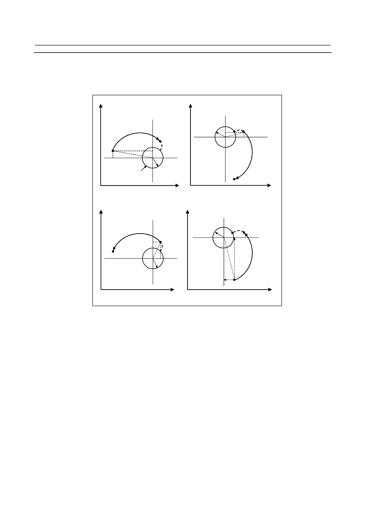
Involute curve machining can be performed by using involute interpolation. Involute interpolation
ensures continuous pulse distribution even in high-speed operation in small blocks, thus enabling smooth
and high-speed machining. Moreover, machining programs can be created more easily, and the size of
machining programs can be reduced.
Yp
Yp
Po
Ps
I
R
End point
Start
0
J
Pe
point
I
Ps
Po
J
0
R
Base circle
Pe End point
Xp
Xp
Clockwise involute interpolation (G02.2)
Yp
Yp
End point
Ro
Pe
Start point
R
End
I
0
Ps
point
Po
Pe
J
J
0
R
I
Ps
Start point
Xp
Xp
Counterclockwise involute interpolation (G03.2)
Fig. 3.1 (a) Actual movement
-
Involute curve
An involute curve on the X-Y plane is defined as follows ;
X (θ) = R [cos θ + (θ - θO) sin θ] + XO
Y (θ) = R [sin θ - (θ - θO) cos θ] + YO
where,
XO, YO
: Coordinates of the center of a base circle
R
: Base circle radius
θO
: Angle of the start point of an involute curve
θ
: Angle of the point where a tangent from the current position to the base circle contacts the
base circle
X (θ), Y (θ) : Current position on the X-axis and Y-axis
- 16 -

B-64484EN-2/02
PROGRAMMING
3.INTERPOLATION FUNCTION
Y
Involute curve
Start point
(X, Y)
R θo
θ
(Xo, Yo)
End point
Base circle
X
Fig. 3.1 (b) Involute curve
Involute curves on the Z-X plane and Y-Z plane are defined in the same way as an involute curve on the
X-Y plane.
-
Start point and end point
The end point of an involute curve is specified using address Xp, Yp, or Zp. An absolute value or
incremental value is used to specify an Xp, Yp, or Zp value. When using an incremental value, specify
the coordinates of the end point viewed from the start point of the involute curve.
When no end point is specified, alarm PS0241 is issued.
If the specified start point or end point lies within the base circle, alarm PS0242 is issued. The same alarm
is issued if cutter compensation C causes the offset vector to enter the base circle. Be particularly careful
when applying an offset to the inside of an involute curve.
-
Base circle specification
The center of a base circle is specified with I, J, and K, corresponding to X, Y, and Z. The value
following I, J, or K is a vector component defined when the center of the base circle is viewed from the
start point of the involute curve; this value must always be specified as an incremental value, regardless
of the G90/G91 setting. Assign a sign to I, J, and K according to the direction.
If I, J, and K are all left unspecified, or I0, J0, K0 is specified, alarm PS0241 or PS0242 is issued.
If R is not specified, or R ≤ 0, alarm PS0241 or PS0242 is issued.
-
Choosing from two types of involute curves
When only a start point and I, J, and K data are given, two types of involute curves can be created. One
type of involute curve extends towards the base circle, and the other extends away from the base circle.
When the specified end point is closer to the center of the base circle than the start point, the involute
curve extends toward the base circle. In the opposite case, the involute curve extends away from the base
circle.
-
Feedrate
The cutting feedrate specified in an F code is used as the feedrate for involute interpolation. The feedrate
along the involute curve (feedrate along the tangent to the involute curve) is controlled to satisfy the
specified feedrate.
-
Plane selection
As with circular interpolation, the plane to which to apply involute interpolation can be selected using
G17, G18, and G19.
-
Cutter compensation
Cutter compensation can be applied to involute curve machining. As with linear and circular interpolation,
G40, G41, and G42 are used to specify cutter compensation.
G40: Cutter compensation cancel
- 17 -

3.INTERPOLATION FUNCTION
PROGRAMMING
B-64484EN-2/02
G41: Cutter compensation left
G42: Cutter compensation right
First, a point of intersection with a segment or an arc is approximated both at the start point and at the end
point of the involute curve. An involute curve passing the two approximated points of intersection with
the start point and end pint becomes the tool center path.
Before selecting the involute interpolation mode, specify G41 or G42, cancel involute interpolation, and
then specify G40. G41, G42, and G40 for cutter compensation cannot be specified in the involute
interpolation mode.
-
Automatic speed control
Cutting precision can be improved by automatically overriding the programmed feedrate during involute
interpolation. See a subsequent subsection, "Automatic Speed Control for Involute Interpolation."
-
Specifiable G codes
The following G codes can be specified in involute interpolation mode:
G04
: Dwell
G10
: Programmable data input
G17
: X-Y plane selection
G18
: Z-X plane selection
G19
: Y-Z plane selection
G65
: Macro call
G66
: Macro modal call
G67
: Macro modal call cancel
G90
: Absolute programming
G91
: Incremental programming
-
Modes that allow involute interpolation specification
Involute interpolation can be specified in the following G code modes:
G41
: Cutter compensation left
G42
: Cutter compensation right
G51
: Scaling
G51.1
: Programmable mirror image
G68
: Coordinate rotation
-
End point error
As shown below the end point may not be located on an involute curve that passes through the start point
(Fig. 3.1 (c)).
When an involute curve that passes through the start point deviates from the involute curve that passes
through the end point by more than the value set in parameter No. 5610, alarm PS0243 is issued.
If there is an end point error, the programmed feedrate changes by the amount of error.
X
End point
Pe
Path after correction
Deviation
Start point
Ps
Correct involute curve
Y
Fig. 3.1 (c) End point error in counterclockwise involute interpolation (G03.2)
- 18 -
B-64484EN-2/02
PROGRAMMING
3.INTERPOLATION FUNCTION
3.1.1
Automatic Speed Control for Involute Interpolation
This function automatically overrides the programmed feedrate in two different ways during involute
interpolation. With this function, a favorable cutting surface can be formed with high precision.
• Override in cutter compensation mode
• Override in the vicinity of basic circle
-
Override in cutter compensation mode
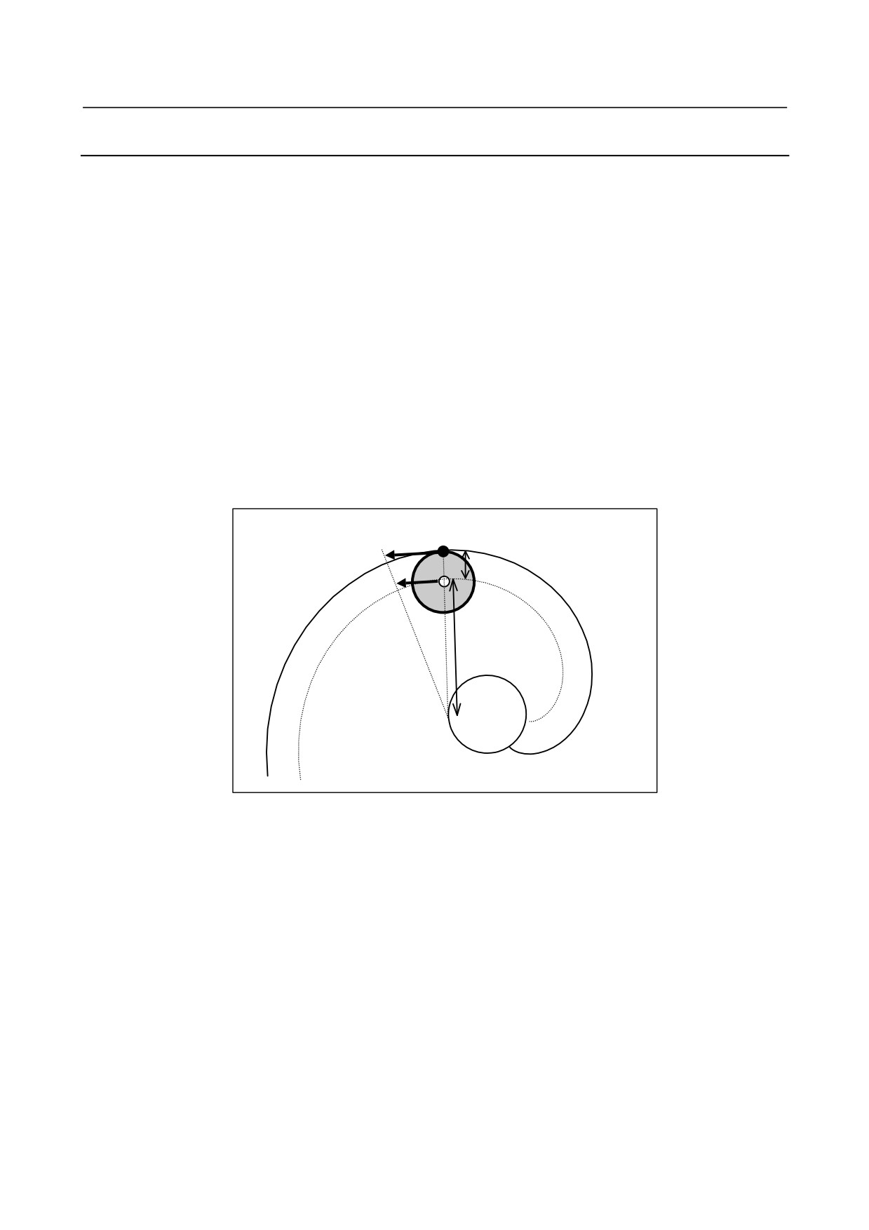
When cutter compensation is applied to involute interpolation, control is exercised in ordinary involute
interpolation so that the tangential feedrate on the tool-center path always keeps the specified feedrate.
Under the control, the actual cutting feedrate (feedrate around the perimeter of the tool (cutting point) on
the path specified in the program) changes because the curvature of the involute curve changes every
moment.
If the tool is offset in the inward direction of the involute curve in particular, the actual cutting feedrate
becomes higher than the specified feedrate as the tool gets nearer to the base circle.
For smooth machining, it is desirable to control the actual cutting feedrate so that the feedrate keeps the
specified feedrate. This function calculates an appropriate override value for the ever-changing curvature
of the involute curve in the involute interpolation mode after cutter compensation. The function also
controls the actual cutting feedrate (tangential feedrate at the cutting point) so that it always keeps the
specified feedrate.
Cutting point
Rofs
Path specified in
the program
Rcp
Base
circle
Fig. 3.1 (d) Override for inward offset by cutter compensation
Inward offset
OVR = Rcp/(Rcp + Rofs) × 100
Outward offset
OVR = Rcp/(Rcp - Rofs) × 100
where,
Rcp :
Radius of curvature at the center of the tool of the involute curve passing through the center of
the tool
Rofs :
Radius of the cutter
-
Clamping the override
The lower limit of override is specified in parameter No. 5620 so that the override for inward offset by
cutter compensation or the override in the vicinity of the basic circle will not bring the speed of the tool
center to zero in the vicinity of the basic circle.
The lower limit of override (OVR1o) is specified in parameter No. 5620 so that the inward offset will not
reduce the speed of the tool center to a very low level in the vicinity of the basic circle.
- 19 -

3.INTERPOLATION FUNCTION
PROGRAMMING
B-64484EN-2/02
Accordingly, the feedrate is clamped but does not fall below the level determined by the programmed
feedrate and the lower limit of override (OVR1o).
The outward offset may increase the override to a very high level, but the feedrate will not exceed the
maximum cutting feedrate.
-
Clamping the acceleration in the vicinity of basic circle
If the acceleration calculated from the radius of curvature of the involute curve exceeds a value specified
in the corresponding parameter, the tangential velocity is controlled so that the actual acceleration will not
exceed the value specified in the parameter. Because the acceleration is always limited to a constant level,
efficient velocity control can be performed for each machine. Because smooth velocity control can be
performed continuously, impacts in machining in the vicinity of the basic circle can be reduced.
To calculate the acceleration, the radius of curvature of the involute curve and the tangential velocity are
substituted into the following formula of circular acceleration:
Acceleration = F × F/R
F: Tangential velocity
R: Radius of curvature
The maximum permissible acceleration is specified in parameter No. 1735.
If the calculated acceleration exceeds the maximum permissible acceleration, the feedrate is clamped to
the level calculated by the following expression:
Clamp level=
Radius of curvature ×Maximum permissible acceleration
If the calculated clamp level falls below the lower limit of feedrate, the lower limit of feedrate becomes
the clamp level. The lower limit of feedrate is specified in parameter No. 1732.
3.1.2
Helical Involute Interpolation (G02.2, G03.2)
As with arc helical involute interpolation, this function performs helical involute interpolation on the two
axes involute interpolation and on up to four other axes simultaneously.
Format
Helical involute interpolation in Xp-Yp plane
G02.2
G17
Xp Yp I J R α β γ δ F
;
G03.2
Helical involute interpolation in Zp-Xp plane
G02.2
G18
Zp Xp K I R α β γ δ F
;
G03.2
Helical involute interpolation in Yp-Zp plane
G02.2
G19
Yp Zp J K R α β γ δ F
;
G03.2
α, β, γ, δ : Optional axis other than the axes of involute interpolation. Up to four axes can
be specified.
- 20 -
B-64484EN-2/02
PROGRAMMING
3.INTERPOLATION FUNCTION
3.1.3
Involute Interpolation on Linear Axis and Rotary Axis
(G02.2, G03.2)
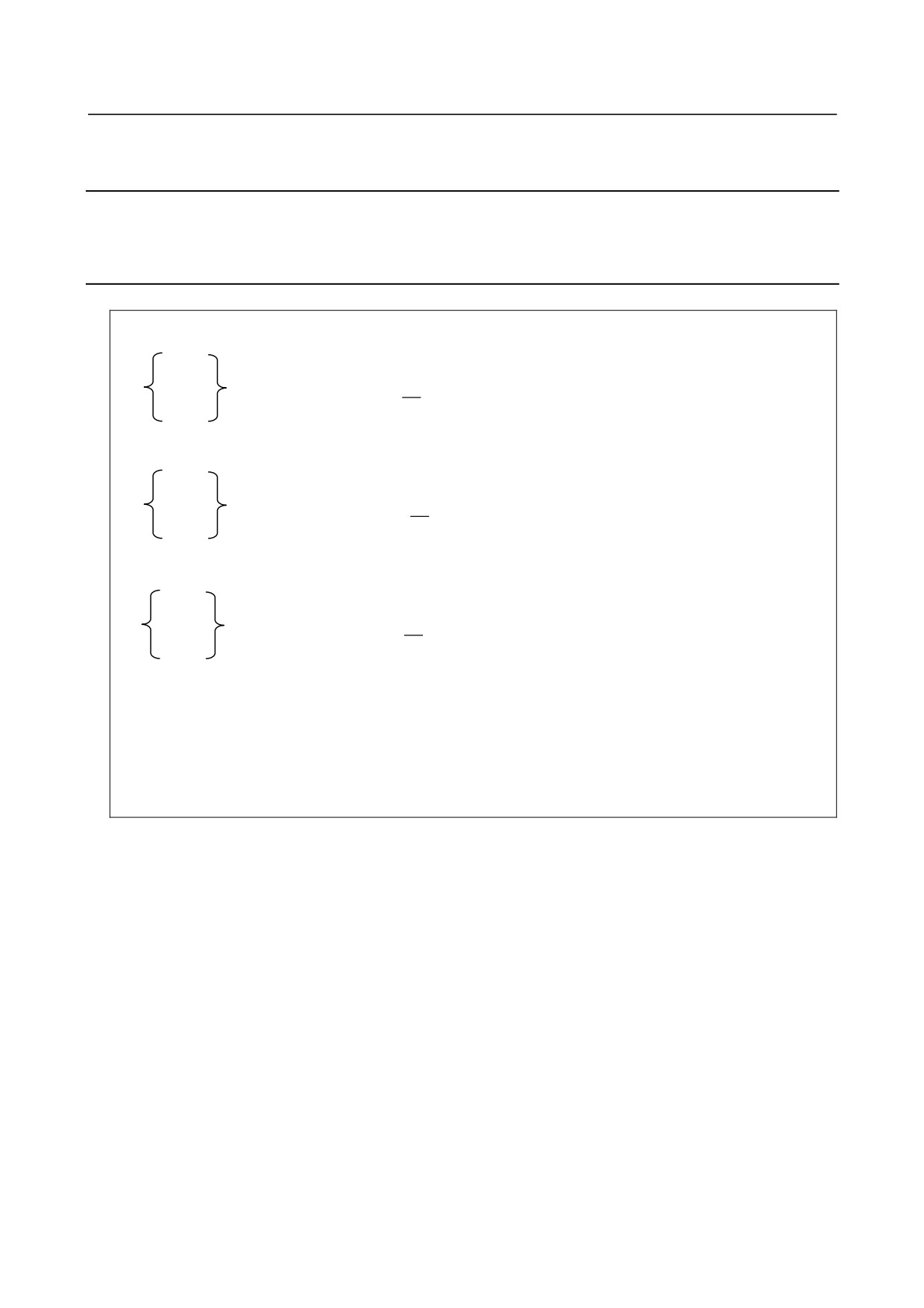
By performing involute interpolation in the polar coordinate interpolation mode, involute cutting can be
carried out. Cutting is performed along an involute curve drawn in the plane formed by a linear axis and a
rotary axis.
Format
If the linear axis is the X-axis or an axis parallel to the X-axis, the plane is considered to
be the Xp-Yp plane, and I and J are used.
G02.2
X C I J R F
;
G03.2
If the linear axis is the Y-axis or an axis parallel to the Y-axis, the plane is considered to
be the Yp-Zp plane, and J and K are used.
G02.2
Y C J K R F
;
G03.2
If the linear axis is the Z-axis or an axis parallel to the Z-axis, the plane is considered to
be the Zp-Xp plane, and K and I are used.
G02.2
Z C K I R F
;
G03.2
G02.2 :
Clockwise involute interpolation
G03.2 :
Counterclockwise involute interpolation
Example) If the linear axis is the X-axis
X, C
:
End point of the involute curve
I, J
:
Center of the basic circle of the involute curve, viewed from the start point
R
:
Radius of basic circle
F
:
Cutting feedrate
- 21 -