FANUC Series 0i-MODEL D, Series 0i Mate-MODEL D. CONNECTION MANUAL (HARDWARE) - page 17

Item 10.5
EMERGENCY STOP SIGNAL
Modified as Following.
Warning
The safety machine should be designed based on the evaluation results of machine risk
assessment. Use the emergency stop signal properly in order to design the safety machine.
To configure an emergency stop circuit in compliance with the safety standards of IEC60204-1 in
which requirements for electrical components of machine are specified, observe the following
cautions. IEC60204-1 specifies that an emergency stop circuit shall function as a category 0 or 1
stop.
Category 0 stop:
Stopping by immediate removal of power to the machine actuators (Uncontrolled stop)
Category 1 stop:
A controlled stop with power to the machine actuators available to achieve the stop and then
removal of power when the stop is achieved
(Controlled stop)
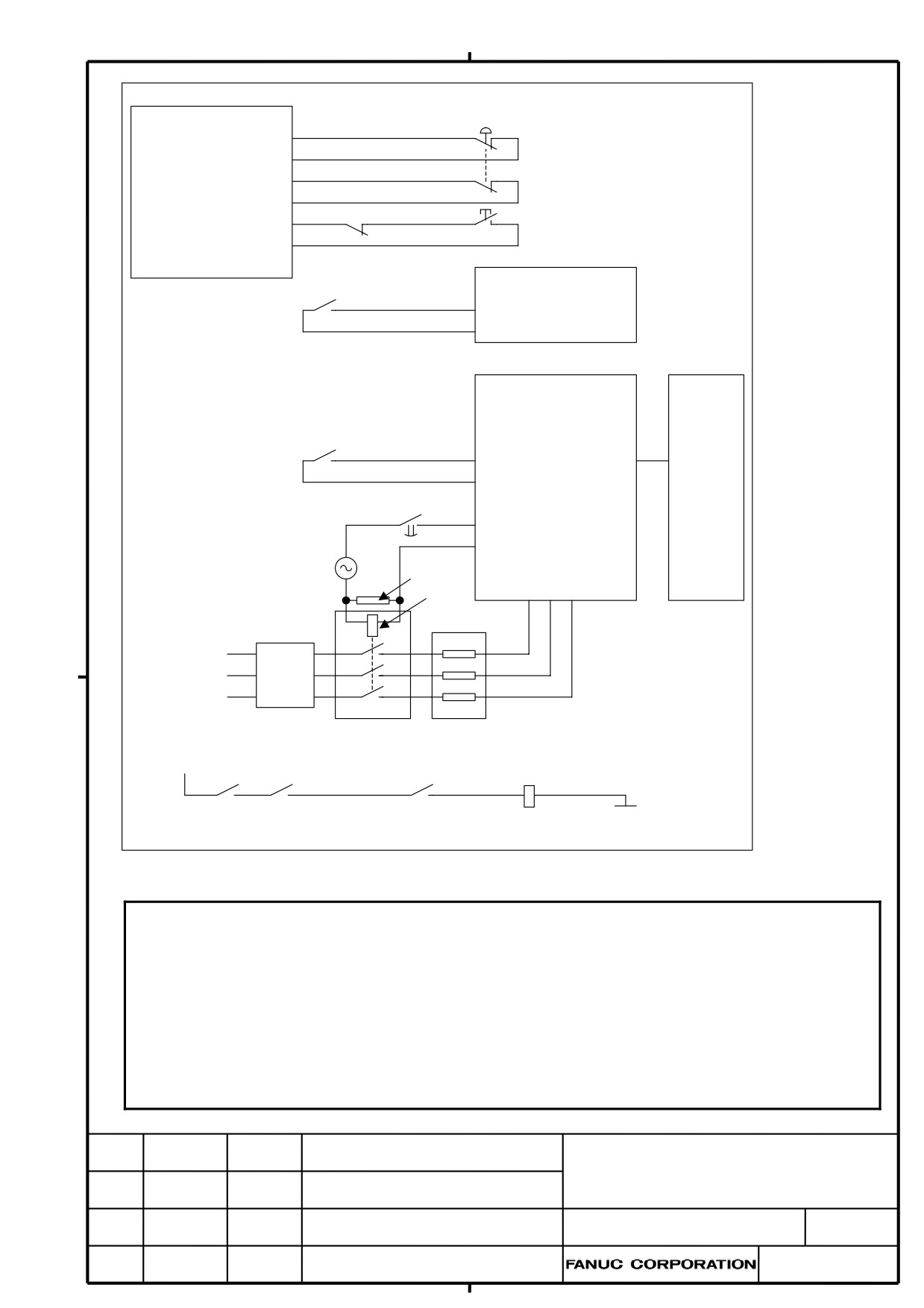
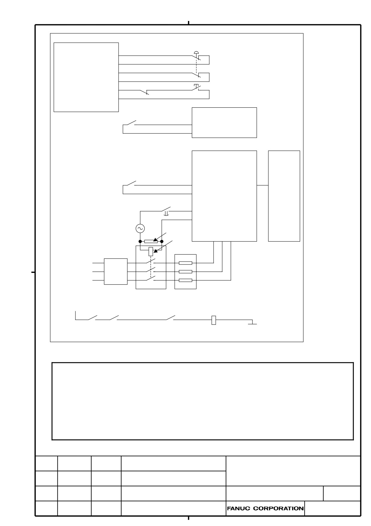
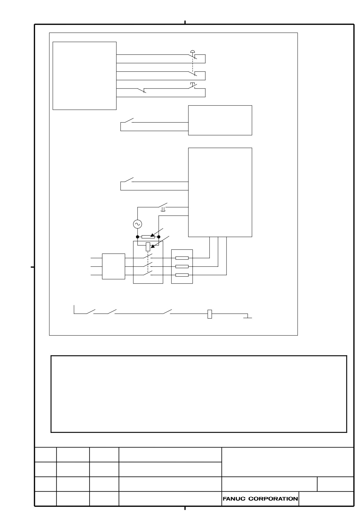
Fig. 10.5(a) or Fig. 10.5(b) or Fig. 10.5(c) shows an example showing how to make connections for
the emergency stop signal with this CNC controller and servo amplifier (αi series or βi series or
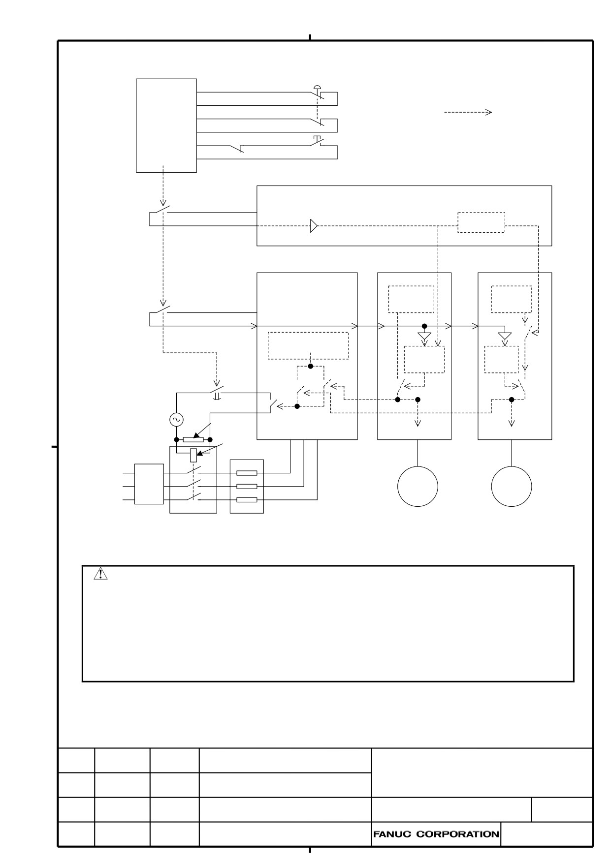
βi SVSP) to comply with the EU Machine Instructions. Fig. 10.5(d) shows a flow diagram of the
emergency stop circuit signals.
The emergency stop signal is input to the Safety relay module. The output signal from the relay is
input to the CNC controller and Power Supply (PS). The Power Supply outputs control signal for a
motor power magnetic contactor, which can be used to switch the power applied to the Power
Supply on and off. An emergency stop signal is usually generated by closing the B contact of a
pushbutton switch.
When the emergency stop signal (*ESP) contact is closed, the CNC controller enters the emergency
stop released state, such that the servo and spindle motors can be controlled and operated.
When the emergency stop signal (*ESP) contact opens, the CNC controller enters the emergency
stop state, and the servo and spindle motors stop. In case of Fig. 10.5(a) or 10.5(b) or 10.5(c), the
spindle motor power is shut off after the spindle motor is decelerated to a stop (Category 1 stop).
Meanwhile, the servo motor is forced to be a dynamic stop as a rule (Category 0 stop). By setting
relevant parameter, however, it is also possible to decelerate the servo motor to a stop, and then to
shut off the servo motor power (Category 1 stop).
Regarding how the Spindle motor or the Servo motor stops when the emergency stop button is
pushed, refer to the Item 10.3 and the Item 10.4. Regarding specifications of parameters related in
these matters, refer to the FANUC AC SERVO parameters manual(B-65270JA).
The example of the emergency stop signal circuit showed in Fig.10.5(a) or Fig. 10.5(b) or Fig.
10.5(c) complies with the requirements of the safety standard ISO13849-1, Performance Level(PL)
c or d. However, when calculating PL value concretely, the calculation should be based on the
safety standard ISO13849-1 with the reliability data provided by each parts supplier. In case for
the reliability data of CNC, please contact FANUC sales office.
ç
ç
ç
ç
TITLE
FANUC Series 0i-MODEL D/
0i Mate-MODEL D
ç
ç
ç
ç
The modification of CONNECTION
ç
ç
ç
ç
MANUAL
ç
ç
ç
ç
ċęĈĞõçĕĖõ
ĊĜĚě.
ç B-64303EN/03-3ç
ĚďČČěç
ČċĐěõ
ċĈěČç
ċČĚĐĎõç
ċČĚĊęĐėěĐĖĕç
3 / 7
ç
ç
Emergency stop
button S1
Safety relay
module
Safety input 1
Emergency
Safety input 2
stop K1
Magnetic contactor K0
Ready S2
Reset/
feedback input
CNC
Emergency stop K1
+24
*ESP
αi series Power Supply
SV
(PS)
SP
Emergency stop K1
+24(CX4)
*ESP
*ESP
*ESP(CX4)
(CXA2A)
(CXA2B)
Emergency stop K1 off delay
MCCOFF3(CX3)
MCCOFF4(CX3)
Power to the magnetic contactor coil
Surge killer
L1 L2 L3
Coil
Main Power
Breaker
Magnetic contactor K0
AC reactor
Break power (+)
Other
CNC conditions
Emergency
Motor brake coil
Break power (-)
conditions
SA
stop K1
Fig. 10.5(a) Example of connections with an αi series servo amplifier
NOTE
1 When Emergency stop button S1 is pushed, Emergency stop K1 opens and Magnetic contactor K0
shuts off the power for Power Supply.
2 Set the off delay timer for shutting the power to the magnetic contactor coil in the above example as
follows:
-
Set a value which allows the time required to normally stop by the spindle.
-
Set a value which allows the feed axis stop time also when the feed axis quick stop function and
vertical axis fall prevention function are used.
3 Connect the auxiliary contact to the feedback input on the Safety relay module in order to detect the
failure of the magnetic contactor K0.
ç
ç
ç
ç
TITLE
FANUC Series 0i-MODEL D/
0i Mate-MODEL D
ç
ç
ç
ç
The modification of CONNECTION
ç
ç
ç
ç
MANUAL
ç
ç
ç
ç
ċęĈĞõçĕĖõ
ĊĜĚě.
ç B-64303EN/03-3ç
ĚďČČěç
ČċĐěõ
ċĈěČç
ċČĚĐĎõç
ċČĚĊęĐėěĐĖĕç
4 / 7
ç
ç
Emergency stop
button S1
Safety relay
module
Safety input 1
Emergency
Safety input 2
stop K1
Magnetic contactor K0
Ready S2
Reset/
feedback input
CNC
Emergency stop K1
+24
*ESP
βi series Power Supply
βi SV
(PS)
Emergency stop K1
+24(CX30)
*ESP
*ESP
*ESP(CX30)
(CXA19A)
(CXA19B)
Emergency stop K1 off delay
RLY1(CX29)
RLY2(CX29)
Power to the magnetic contactor coil
Surge killer
L1 L2 L3
Coil
Main Power
Breaker
Magnetic contactor K0
AC reactor
Break power (+)
Other
CNC conditions
Emergency
Motor brake coil
Break power (-)
conditions
SA
stop K1
Fig. 10.5(b) Example of connections with an βi series servo amplifier
NOTE
1 When Emergency stop button S1 is pushed, Emergency stop K1 opens and Magnetic contactor K0
shuts off the power for Power Supply.
2 Set the off delay timer for shutting the power to the magnetic contactor coil in the above example as
follows:
-
Set a value which allows the time required to normally stop by the spindle.
-
Set a value which allows the feed axis stop time also when the feed axis quick stop function and
vertical axis fall prevention function are used.
3 Connect the auxiliary contact to the feedback input on the Safety relay module in order to detect the
failure of the magnetic contactor K0.
ç
ç
ç
ç
TITLE
FANUC Series 0i-MODEL D/
0i Mate-MODEL D
ç
ç
ç
ç
The modification of CONNECTION
ç
ç
ç
ç
MANUAL
ç
ç
ç
ç
ċęĈĞõçĕĖõ
ĊĜĚě.
ç B-64303EN/03-3ç
ĚďČČěç
ČċĐěõ
ċĈěČç
ċČĚĐĎõç
ċČĚĊęĐėěĐĖĕç
5 / 7
ç
ç
Emergency stop
button S1
Safety relay
module
Safety input 1
Emergency
Safety input 2
stop K1
Magnetic contactor K0
Ready S2
Reset/
feedback input
CNC
Emergency stop K1
+24
*ESP
βi SVSP Servo Amplifier
(PS)
Emergency stop K1
+24(CX4)
*ESP(CX4)
Emergency stop K1 off delay
RLY1(CX3)
RLY2(CX3)
Power to the magnetic contactor coil
Surge killer
L1 L2 L3
Coil
Main Power
Breaker
Magnetic contactor K0
AC reactor
Break power (+)
Other
CNC conditions
Emergency
Motor brake coil
Break power (-)
conditions
SA
stop K1
Fig. 10.5(c) Example of connections with an βi SVSP servo amplifier
NOTE
1 When Emergency stop button S1 is pushed, Emergency stop K1 opens and Magnetic contactor K0
shuts off the power for Power Supply.
2 Set the off delay timer for shutting the power to the magnetic contactor coil in the above example as
follows:
-
Set a value which allows the time required to normally stop by the spindle.
-
Set a value which allows the feed axis stop time also when the feed axis quick stop function and
vertical axis fall prevention function are used.
3 Connect the auxiliary contact to the feedback input on the Safety relay module in order to detect the
failure of the magnetic contactor K0.
ç
ç
ç
ç
TITLE
FANUC Series 0i-MODEL D/
0i Mate-MODEL D
ç
ç
ç
ç
The modification of CONNECTION
ç
ç
ç
ç
MANUAL
ç
ç
ç
ç
ċęĈĞõçĕĖõ
ĊĜĚě.
ç B-64303EN/03-3ç
ĚďČČěç
ČċĐěõ
ċĈěČç
ċČĚĐĎõç
ċČĚĊęĐėěĐĖĕç
6 / 7
ç
ç
Emergency
stop button S1
Broken line indicates
Safety
the signal flow of Data
relay module
or logic.
Emergency
Stop
Magnetic contactor K0
Ready S2
K1
CNC
Emergency stop K1
+24
Contact input
*ESP(X8.4)
Delay timer
*ESP(spindle)
Internal signal
Internal signal
αi series Power Supply
SP
SV
(PS)
PWM on
PWM
Emergency stop K1
command
on
24V
Contact input
*ESP
Magnetic contactor
on command
0 after the
Delay
spindle
timer
stops
Emergency stop K1 off delay
Internal
signal
Internal
signal
Power to the
magnetic
Surge Killer
contactor coil
Power shut-off
Power shut-off
Coil
Breaker
Motor
Motor
Main Power
MCC K0
AC reactor
Fig. 10.5(d) Flow diagram of emergency stop circuit signals
CAUTION
1 This CNC controller can detect overtravel by using a software limit function. If the software limit
function does not operate effectively due to a failure, resulting in a possible serious accident or
loss, install a safety circuit, for example, a stroke end limit switch arranged in series with the
emergency stop button.
2 To use a spindle motor and amplifier produced by a manufacturer other than FANUC, refer to
the corresponding documentation as well as this manual. Design the emergency stop
sequence such that, if the emergency stop signal contact opens while the spindle motor is
rotating, the spindle motor is decelerated until it stops.
ç
ç
ç
ç
TITLE
FANUC Series 0i-MODEL D/
0i Mate-MODEL D
ç
ç
ç
ç
The modification of CONNECTION
ç
ç
ç
ç
MANUAL
ç
ç
ç
ç
ċęĈĞõçĕĖõ
ĊĜĚě.
ç B-64303EN/03-3ç
ĚďČČěç
ČċĐěõ
ċĈěČç
ċČĚĐĎõç
ċČĚĊęĐėěĐĖĕç
7 / 7
ç
ç
FANUC Series 0i-MODEL D
FANUC Series 0i Mate-MODEL D
CONNECTION MANUAL (HARDWARE)
Correction of APPENDIX G
1. Type of applied technical documents
FANUC Series 0i-MODEL D
Name
FANUC Series 0i Mate-MODEL D
CONNECTION MANUAL (HARDWARE)
Spec. No.
B-64303EN/03
/ Version
2. Summary of change
New, Add.,
Applicable
Group
Name / Outline
Correct, Del.
Date
Basic
Function
Optional
Function
Correction of the description of parameter
setting
(APPENDIX G. section 11)
ATR value for the slaves on the FSSB line
Unit
Original: No.14340 to 14349
Correct
At once
Correction: No. 14340 to 14357
Refer to following pages of this report for corrected
G.11.
Maintenance
Parts
Notice
Correction
Another
Title
FANUC Series 0i/0i Mate -MODEL D
CONNECTION MANUAL (HARDWARE)
Correction of APPENDIX G
Drawing No.
CUST.
B-64303EN/03-04
01
2011/5/25
Otsuki
New issue
Edit.
Date
Designer
Description
SHEET
1 / 7
G.11 PARAMETER SETTING
(1) At emergency stop, turn on the power of CNC.
(2) Follow the procedure below to set parameters concerned with FSSB.
In the case of using Analog servo adapter, the FSSB automatic setting function is not available. It is
necessary to set the value of No.1023, No.1815, No.1905, No.14340 to14357, No.14376 to 14391 and
No.1936 to 1937 in the manual setting No.2 mode. Refer to “FSSB setting” of the connection manual
(function edition) about the detail of the setting.
When this parameter is set, Analog servo adapter is basically treated in the similar way to the separate
type detector interface unit. (After this, Analog servo adapter and the separate type detector interface unit
are called “an interface unit”.)
Follow the explanation below and the Parameter Manual (B-64310EN) of CNC and set the appropriate
value.
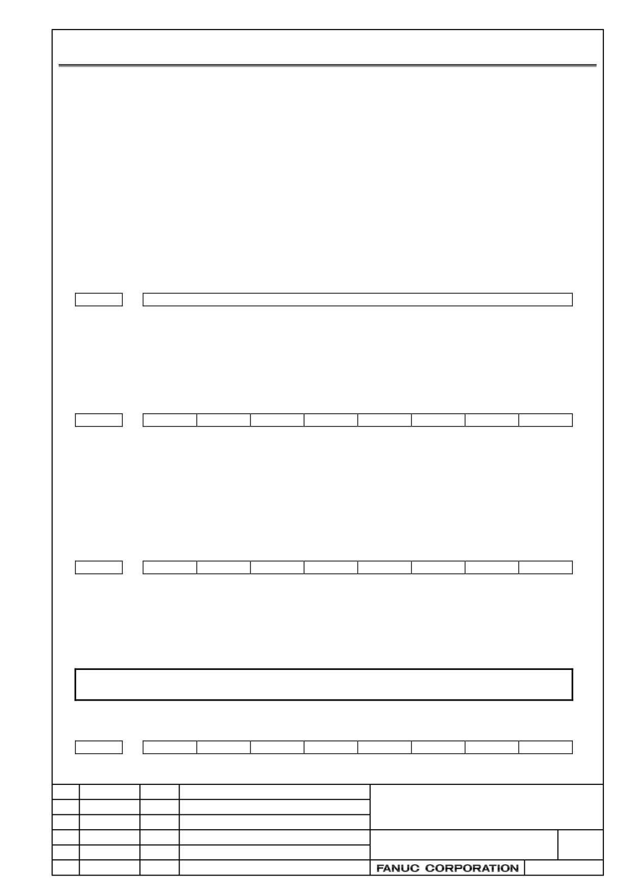
•
Setting of servo axis number
No.
1023
Number of the servo axis for each axis
[Data type] Byte axis
[Valid data range] 1,2,3,…controllable axis number
Set the servo axis number for each axis. Refer to the “FSSB setting” of Connection Manual
(Function) (B-64303EN-1).
•
Setting of the position detector
No.
7
6
5
4
3
2
1
0
1815
APC
APZ
APC 0: Position detector is other than absolute pulse coder.
1: Position detector is absolute pulse coder.
APZ Zero position of absolute pulse coder is:
0: Not established.
1: Established. (Automatically set to 1 after the zero position is established.)
•
FSSB manual setting
No.
7
6
5
4
3
2
1
0
1902
FMD
[Data type] Byte axis
FMD The setting mode of FSSB is
0: Automatic.
1: Manual setting 2.
NOTE
If you want to use Analog servo adapter, set 1.
•
Setting of bit parameter
No.
7
6
5
4
3
2
1
0
1905
PM2
PM1
Title
Drawing No.
CUST.
B-64303EN/03-04
Edit.
Date
Designer
Description
SHEET
2 / 7
[Data type] Bit axis
PM1 The first interface unit is:
0: Not used.
1: Used.
PM2 The second interface unit is:
0: Not used.
1: Used.
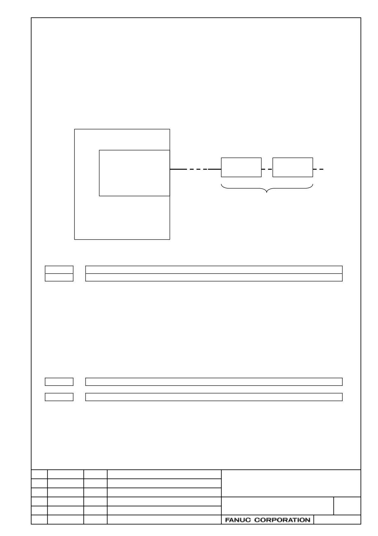
The interface unit that is connected to the FSSB line on a servo card and is near the CNC is the
first interface unit (1st IF unit). Another one connected to the FSSB line is the second interface
unit (2nd IF unit).
CNC
Servo card
FSSB line
1st IF unit
2nd IF unit
COP10A-1
PM1
PM2
Two IF units (max)
•
Setting connector number
No.
1936
Connector number of the first interface unit
1937
Connector number of the second interface unit
[Data type] Byte axis
[Valid data range] 0 to 3 (in case of Analog servo adapter)
0 to 7 (in case of separate type detector interface unit)
In case of using interface unit, set the value, which subtracts 1 from the connector number of
each axis. (In case of using Analog servo adapter, set 0 to 3 to the axes connected with
connector JV1nL to JV4nL.)
Set 0 to the axis without interface unit.
It is possible to use any connectors at any axis.
•
Setting Address Conversion Table for slave number
No.
14340
ATR value corresponding to slave 01 on the FSSB line
to
14357
ATR value corresponding to slave 18 on the FSSB line
[Data type] Byte
[Valid data range] 0 to 7, 64, -56, -96
The amplifier or interface unit connected to CNC by the optical cable is called “Slave”. Each
one axis servo amplifier or one interface unit (with or without the additional unit) consists of
one slave. Two axes amplifier consists of two slaves and three axes amplifier consists of three
slaves.
Title
Drawing No.
CUST.
B-64303EN/03-04
Edit.
Date
Designer
Description
SHEET
3 / 7
The analog servo amplifier is numbered as if it was connected from the terminal slave (the
most far slave from CNC). Each one-axis analog servo amplifier is numbered one slave
number. For example, if the terminal unit connected to FSSB is slave 5, the analog servo
amplifiers are numbered from 6. (Refer to the example described later.)
This parameter is set as follows.
-
In case of amplifier (including analog amplifier):
Set a value obtained by subtracting 1 from the setting of parameter No.1023 for the axis
to which the amplifier is assigned.
-
In case of interface unit:
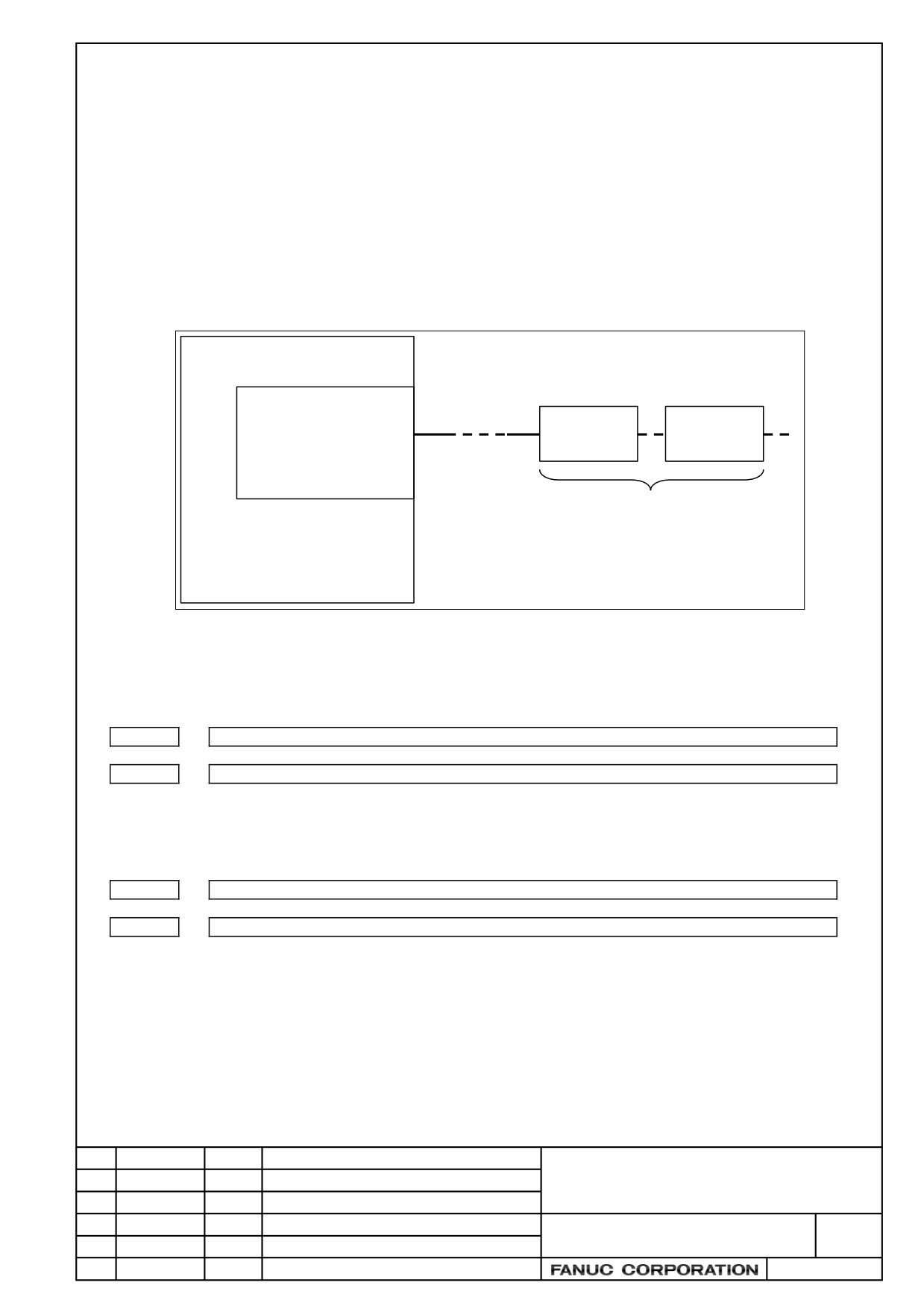
Set 64 for 1st interface unit and set -56 for the 2nd interface unit respectively.
Please see below figure.
CNC
Servo card
FSSB line
1st IF unit
2nd IF unit
COP10A-1
ATR=64
ATR= -56
Two IF units (max)
-
In case of no slave:
Set -96.
•
Setting Address Conversion Table for connector
No.
14376
ATR value corresponding to connector 1 on the 1st interface unit
to
14383
ATR value corresponding to connector 8 on the 1st interface unit
[Data type] Byte
[Valid data range] 0 to 7 and 32
No.
14384
ATR value corresponding to connector 1 on the 2nd interface unit
to
14391
ATR value corresponding to connector 8 on the 2nd interface unit
[Data type] Byte
[Valid data range] 0 to 7 and 32
Each of these parameters sets the value(ATR value) of the address translation table
corresponding to each connector on a interface unit.
In each of these parameters, set a value obtained by subtracting 1 from the setting of parameter
No.1023 for the axis connected to a connector on an interface unit.
When there is an axis for which bit 6 or 7 of parameter No.1905 is set to use an interface unit,
set 32 for those connectors that are not used.
Title
Drawing No.
CUST.
B-64303EN/03-04
Edit.
Date
Designer
Description
SHEET
4 / 7
(3) Turning off/on the power to CNC
The description of setting continues to 4. Servo initial setting.
(Reference)
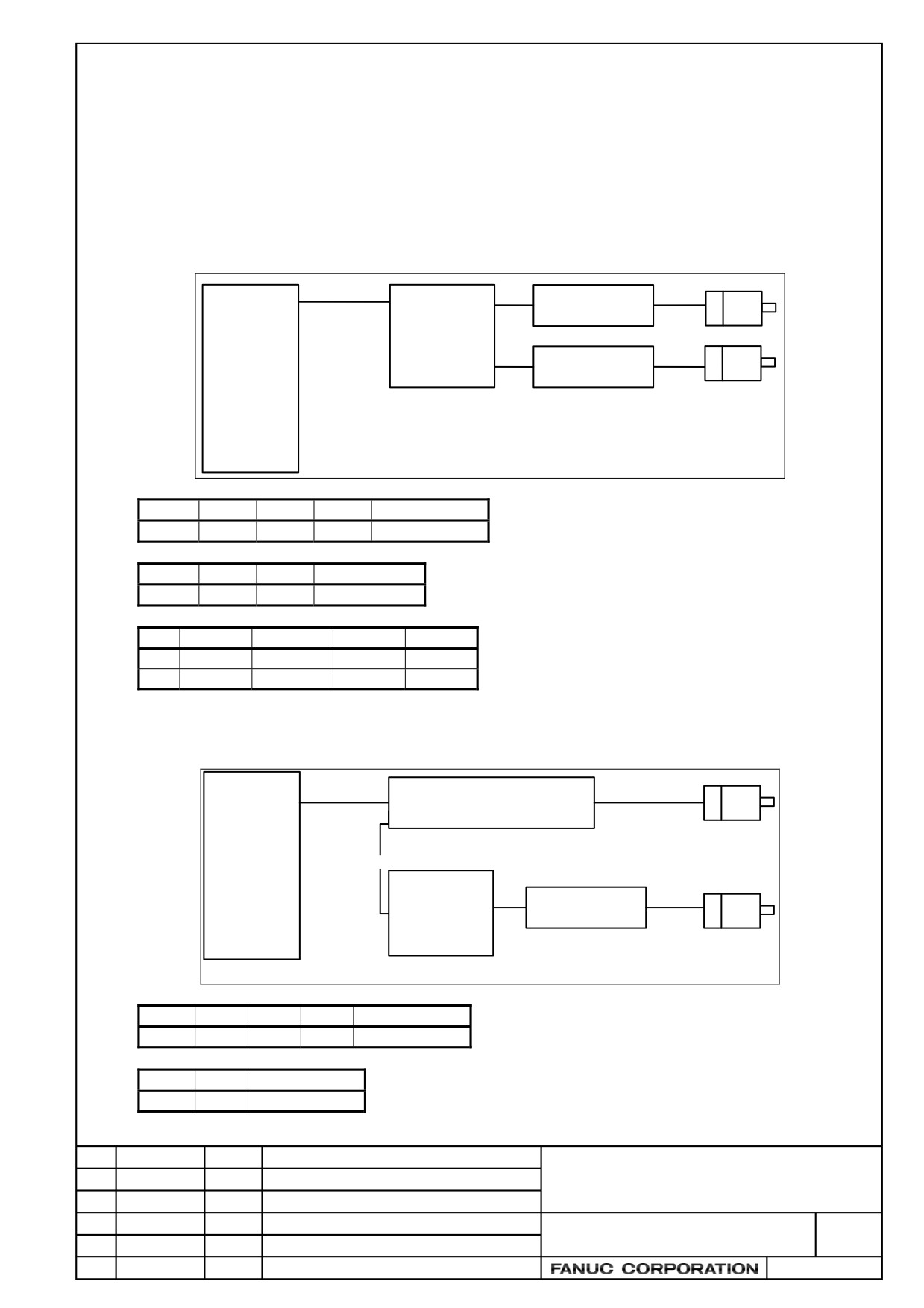
FSSB Setting example in case of using Analog servo adapter
[Example 1 : in case of two analog servo axis]
Analog servo adapter is slave 1. Analog servo amplifiers are considered as they are connected after
Analog servo adapter. So they are slaves 2 and 3.
FSSB
X axis
JV11L
Analog servo
Analog servo
amplifier 1
adapter
Slave 2
(Basic unit)
Y axis
JV12L
Analog servo
amplifier 2
CNC
Slave 1
Slave 3
No.
14340
14341
14342
14343 to 14357
Value
64
0
1
-96
No.
14376
14377
14378 to 14383
Value
0
1
32
No.
No.1023
No.1905
No.1936
No.1937
X
1
01000000
0
0
Y
2
01000000
1
0
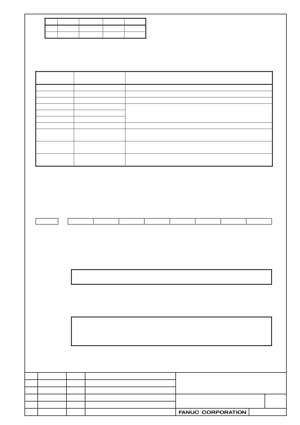
[Example 2 : in case of one digital and one analog servo axis]
Digital servo amplifier is slave 1 and Analog servo adapter is slave 2. Analog servo amplifier is slave 3.
FSSB
X axis
Digital servo amplifier
Slave 1
FSSB
CNC
Analog servo
JV11L
Analog amplifier
Y axis
adapter
(Basic unit)
Slave 3
Slave 2
No.
14340
14341
14342
14343 to 14357
Value
0
64
1
-96
No.
14376
14377 to 14383
Value
1
32
Title
Drawing No.
CUST.
B-64303EN/03-04
Edit.
Date
Designer
Description
SHEET
5 / 7
No.
No.1023
No.1905
No.1936
No.1937
X
1
00000000
0
0
Y
2
01000000
0
0
(4)
Initial setting of servo parameter
Set the following of analog servo axis.
Parameter
Description
Data
number
No.2000
Automatic setting
00000000
No.2020
Motor type
252
No.2001
AMR
00000000
No.1820
CMR
Set the value similar to the one of digital servo according to mechanical
No.2084
F × FG (Numerator)
system.
No.2085
F × FG (Denominator)
No.2022
Rotation direction
111 (CCW) or -111 (CW)
No.1821
Reference counter size
Set the number (after F×FG) of pulse per one motor revolution as digital
servo.
No.2023
Feedback pulse for
Set value = 1536.797 × E
velocity detection
E : the voltage (V) proportional to the 1000min-1 velocity command
No.2024
Feedback pulse for
Set the number (before F × FG) of pulse per one motor revolution as
position detection
digital servo.
(5)
Power OFF/ON
(6)
Setting to validate the analog servo interface function
Set the following of analog servo axis.
No.
7
6
5
4
3
2
1
0
2009
ANALOGG
SERDMY
[Data type] Bit axis
SERDMY The serial feedback dummy function is:
0: Invalidated.
1: Validated.
NOTE
In case of analog servo axis, set 1.
ANALOG The analog servo interface function is:
0: Invalidated.
1: Validated.
NOTE
In case of analog servo axis, set 1.
After setting this bit, please turn off the power of CNC more than
one time.
Title
Drawing No.
CUST.
B-64303EN/03-04
Edit.
Date
Designer
Description
SHEET
6 / 7
No.
2165
Maximum amplifier current
[Data type] Byte axis
NOTE
In case of analog servo axis, set 0.
When the initial setting of servo shown in previous section is done, 45 is set to this address
automatically. But clear this parameter to be 0. (If this parameter of analog servo axis is not 0,
the combination alarm of motor and amplifier will emerge.)
Title
Drawing No.
CUST.
B-64303EN/03-04
Edit.
Date
Designer
Description
SHEET
7 / 7
Addition and correction of
FAUMC Series 0i-MODEL D
CONNECTION MANUAL (HARDWARE)
1. Type of applied technical documents
Name
FANUC Series 0i-MODEL D
CONNECTION MANUAL (HARDWARE)
Spec.No./Version
B-64303EN/03
2. Summary of change
Group
Name / Outline
New, Add,
Applicable
Correct,
Date
Delete
Basic
Function
Optional
Function
Unit
Maintenance
parts
Notice
Correction
Another
The module specifications of extension module C for
Immediately
connection to the I/O Link i is corrected and added.
Item 9.11.2.3 I/O signal specifications
Add
Item 9.11.6.2 DO alarm detection
Add, Correct
TITLE
Addition and correction of
FANUC Series 0i -MODEL D
CONNECTION MANUAL (HARDWARE)
DRAW. NO.
CUST.
01
11.07.04
Yamanak
First issue
B-64303EN/03-05
SHEET
EDIT.
DATE
DESIG.
DESCRIPTION
1/3
Item 9.11.2.3 Note is added.
9.11.2.3 I/O signal specifications
Basic module、Extension modules A and B
WARNING
1 The protection function is intended to protect the components internal to the modules
rather than external units.
2 No protection function of modules can protect their internal components in all cases.
Once any protection function has worked, remove the cause promptly. If an absolute
maximum rating is exceeded, for example, it is likely that protection functions may not
work or an IC may break down before the related protection function works, depending
on the way or situation in which the modules are used.
3 If an output protection function is defective, it is likely that, if the load current exceeds
its rating continuously for a long time, smoke or ignition may occur.
Extension module C
WARNING
1 The protection function is intended to protect the components internal to the modules
rather than external units.
2 No protection function of modules can protect their internal components in all cases.
Once any protection function has worked, remove the cause promptly. If an absolute
maximum rating is exceeded, for example, it is likely that protection functions may not
work or an IC may break down before the related protection function works, depending
on the way or situation in which the modules are used.
3 If an output protection function is defective, it is likely that, if the load current exceeds
its rating continuously for a long time, smoke or ignition may occur.
TITLE
Addition and correction of
FANUC Series 0i -MODEL D
CONNECTION MANUAL (HARDWARE)
DRAW. NO.
CUST.
01
11.07.04
Yamanak
First issue
B-64303EN/03-05
SHEET
EDIT.
DATE
DESIG.
DESCRIPTION
2/3
Item 9.11.6.2 Note is corrected and added.
9.11.6.2 DO alarm detection
States when the protection function is activated in extension module C
CAUTION
1 If the overheat protection function or over voltage protection function among the
protection functions above is activated, the DO bit is kept OFF until the cause is
eliminated. When the cause is eliminated, the DO bit is set to ON without restarting
the system.
2 Disconnection detection is performed by monitoring, with an output element in the
module, the current flowing through a load when DO output is ON. When the detected
current value is about 200 mA or less, disconnection detection is assumed. So, when
a device (such as an LED) with a small load current is connected, the DO alarm state
results, assuming disconnection detection. Unlike the other protection functions,
however, this function does not turn off DO output. If a connection is reactivated after
the state of disconnection is once set, disconnection detection is canceled without
restarting the system.
3 When the ratings current value of the load is larger than the disconnection detection
current value, and the rise time of the current that flows to the connected load (such
as an solenoid) is late, the disconnection detection function might work. For that
case, the disconnection detecting function when DO output is ON can be evaded by
programming it to refer to DO alarm allocated to DI after the fixed time has passed
since DO was turned on.
TITLE
Addition and correction of
FANUC Series 0i -MODEL D
CONNECTION MANUAL (HARDWARE)
DRAW. NO.
CUST.
01
11.07.04
Yamanak
First issue
B-64303EN/03-05
SHEET
EDIT.
DATE
DESIG.
DESCRIPTION
3/3
FANUC Series 0i-MODEL D/0i Mate-MODEL D
The modification of CONNECTION MANUAL (HARDWARE)
(B-64303EN/03)
1.Type of applied technical documents
FANUC Series 0i-MODEL D/0i Mate-MODEL D
Name
CONNECTION MANUAL (HARDWARE)
Spec.No.
B-64303EN/03
/Version
2.Summary of change
New,Add,
Applicable
Group
Name/Outline
Correct,Delete
Date
Basic
Function
Optional
Function
Unit
Maintenance
Parts
Notice
Correction
This document describes about the additonof the USB interface to
the CNC control unit(8.4” color LCD/MDI horizontal type, vertical
type and 10.4” color LCD) listed in APPENDIX A. EXTERNAL
DIMENSIONS OF EACH UNIT.
Others
Description “With or without USB interface, there is no difference
in external dimension and installation dimension.” is added.
Description “The unit with a touch panel has no soft keys.” is
deleted.
FANUC Series 0i-MODEL D/0i Mate-MODEL D
The modification of CONNECTION MANUAL
(HARDWARE)
CUST.
01
27.12.11
Osa
Fist issued.
B-64303EN/03-06
Edit
Date
Design
Description
1/4
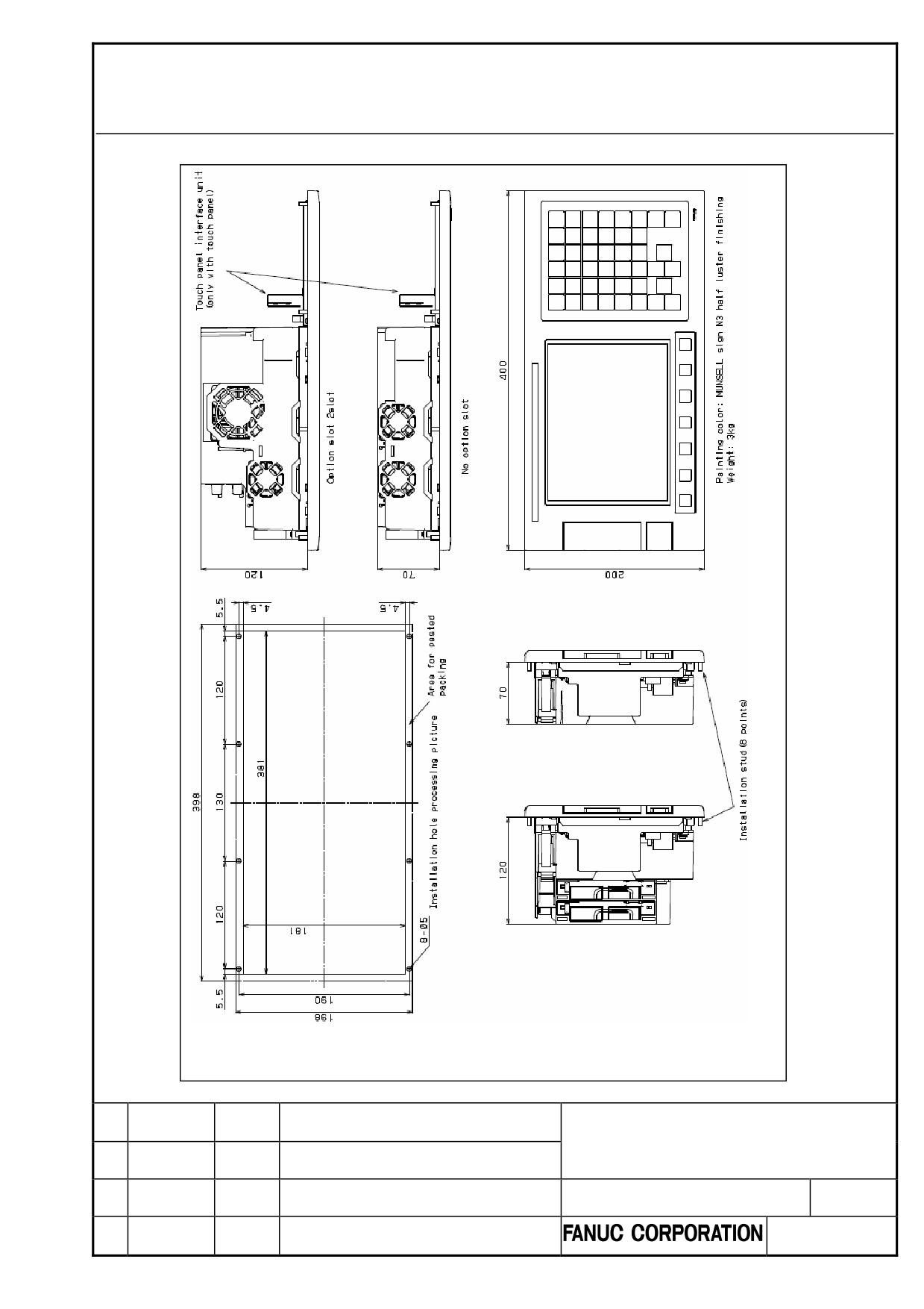
A.EXTERNAL DIMENTIONS
OF EACH UNIT
APPENDIX
B-64303EN/03
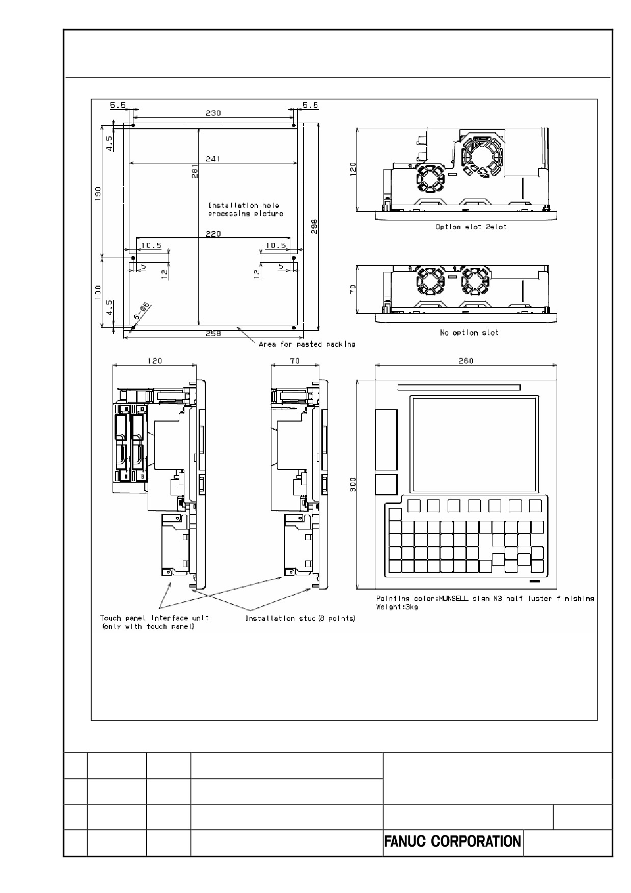
Fig. U1
CNC control unit (8.4” color LCD/MDI horizontal type)
NOTE The unit is installed from outside cabinet.
Fix with M4 nut from the reverse side. The tightening torque is 2.0 N・m.
With or without USB interface, there is no difference in external dimension
and installation dimension.
-370-
FANUC Series 0i-MODEL D/0i Mate-MODEL D
The modification of CONNECTION MANUAL
(HARDWARE)
CUST.
B-64303EN/03-06
Edit
Date
Design
Description
2/4
A.EXTERNAL DIMENTIONS
OF EACH UNIT
APPENDIX
B-64303EN/03
Fig. U2
CNC control unit (8.4” color LCD/MDI vertical type)
NOTE The unit is installed from outside cabinet.
Fix with M4 nut from the reverse side. The tightening torque is 2.0 N・m.
With or without USB interface, there is no difference in external dimension
and installation dimension.
-371-
FANUC Series 0i-MODEL D/0i Mate-MODEL D
The modification of CONNECTION MANUAL
(HARDWARE)
CUST.
B-64303EN/03-06
Edit
Date
Design
Description
3/4
A.EXTERNAL DIMENTIONS
OF EACH UNIT
APPENDIX
B-64303EN/03
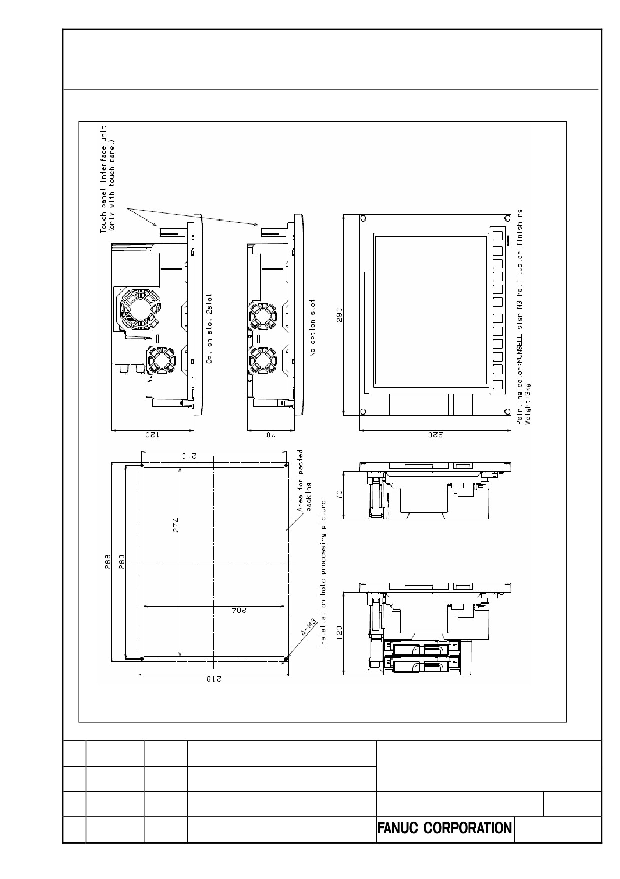
Fig. U3
CNC control unit (10.4” color LCD)
NOTE
The unit is stopped with the screw from outside of the cabinet, then
install the screw cap.
With or without USB interface, there is no difference in external dimension
and installation dimension.
-372-
FANUC Series 0i-MODEL D/0i Mate-MODEL D
The modification of CONNECTION MANUAL
(HARDWARE)
CUST.
B-64303EN/03-06
Edit
Date
Design
Description
4/4
FANUC Series 0i-MODEL D/0i Mate-MODEL D
The modification of CONNECTION MANUAL (HARDWARE)
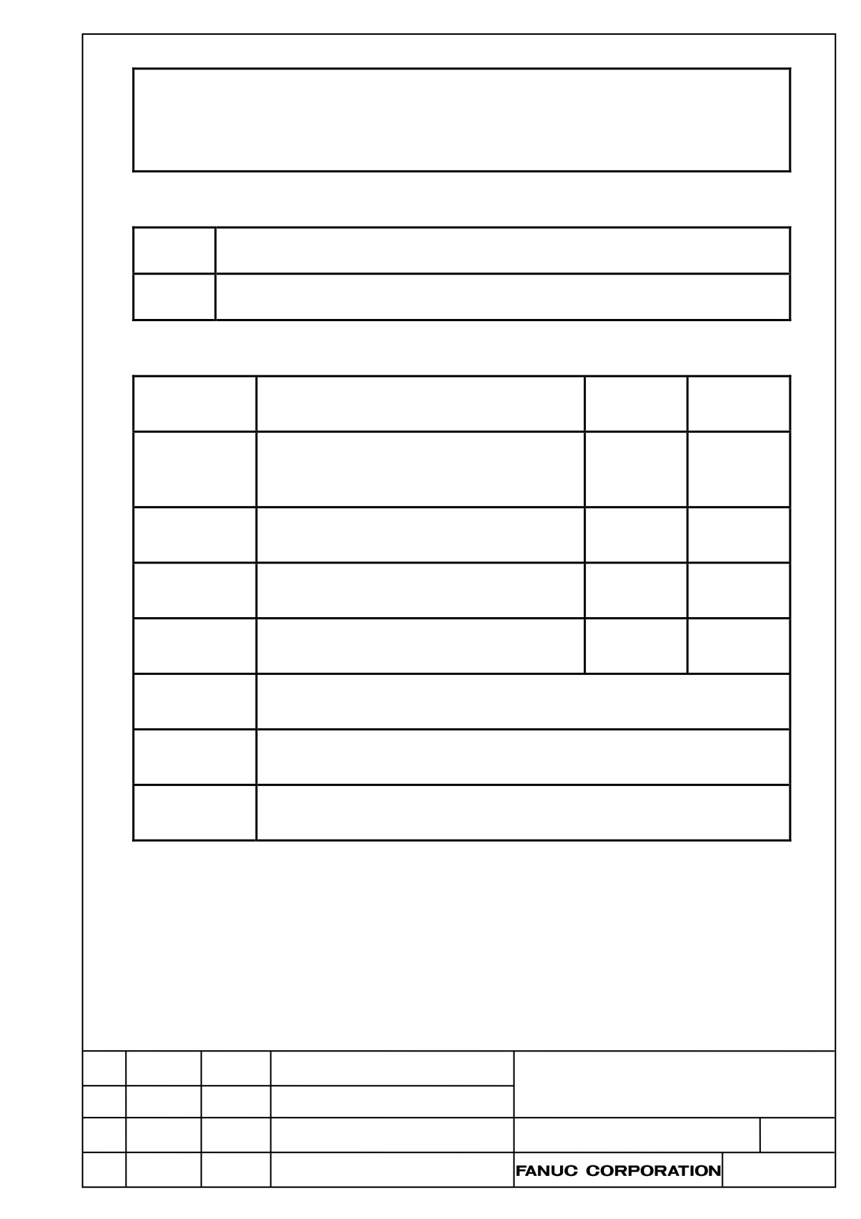
1.
Type of applied technical documents
FANUC Series 0i-MODEL D/0i Mate-MODEL D
Name
CONNECTION MANUAL (HARDWARE)
Spec. No.
B-64303EN/03
/ Version
2.
Summary of change
New, Add.,
Applicable
Group
Name / Outline
Correct, Del.
Date
To replace descriptions of following items as
Basic
attached documents.
Correct
Immediately
Function
6.2 ANALOG SPINDLE
6.3 POSITION CODER
Optional
Function
Unit
Maintenance
Parts
Notice
Correction
Another
TITLE
Mate-MODEL D
FANUC Series 0i-MODEL D/0i
The modification of CONNECTION MANUAL
(HARDWARE)
DRAW. NO
CUST.
01
12.03.22
Otsuki
First issue
B-64303EN/03-06
Edit.
DATE
Design
Description
SHEET
1/ 7
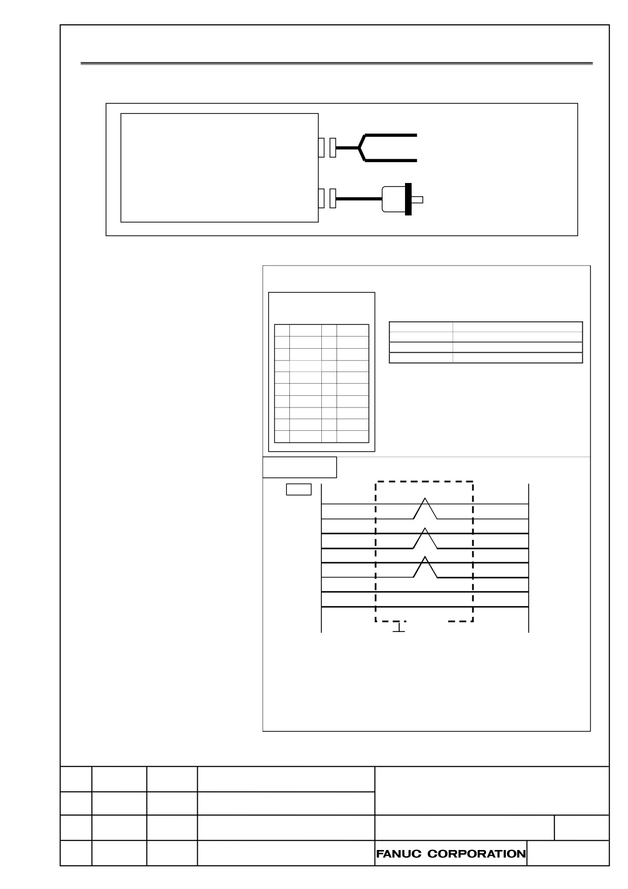
6.2
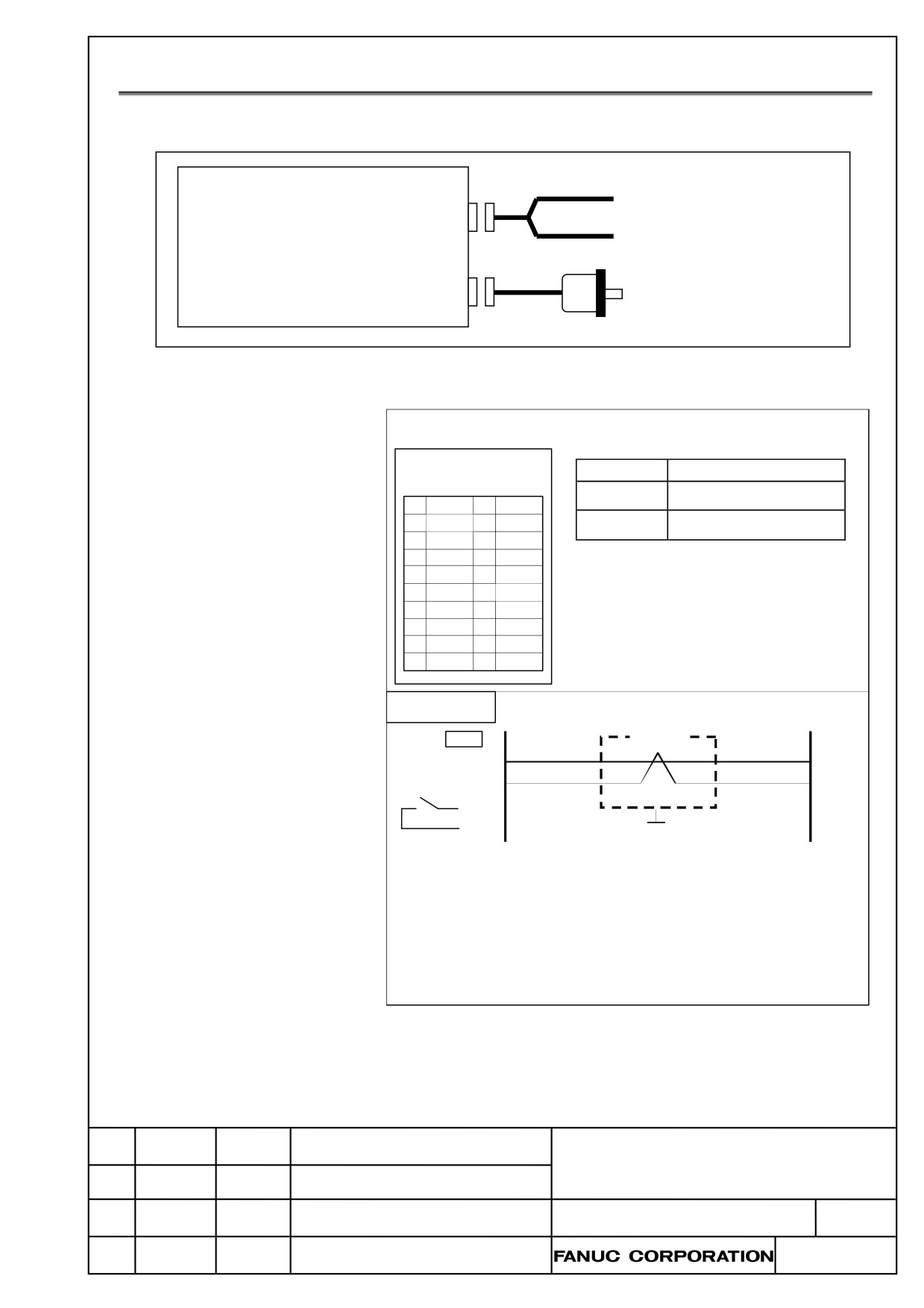
ANALOG SPINDLE
Connection
MAIN BOARD
Analog spindle output
A-OUT & HDI(JA40)
(High-speed skip input)
POS(JA41)
Position coder
Analog spindle interface
Control unit
JA40
Signal Name
Description
FI80-20P,DF1R020WB1
(PC R-EV20MDT)
SVC, ES
Spindle command voltage
1
(
)
11
(
)
and common line
ENB1, ENB2
Spindle enable signal
2
12
(Note1)
3
(
)
13
(
)
4
14
5
ES
15
(
)
(
)
6
16
7
SVC
17
(
)
8
ENB1
18
9
ENB2
19
(
)
10
20
Cable
SH IELD
JA40
7
SVC
5
ES
ENB1
ENB2
GROUNDING PLATE
RECOMMENDED CABLE SPECIFICATION:
A66L-0001-0284#10P (#28AW G×10 pairs)
RECOMMENDED CABLE-SIDE CONNECTOR:
PC R-E20FA (Honda Tsushin Kogyo)
FI30-20S (Hirose Electric)
FCN-247J020-G/E (FUJITSU COMPONENT)
52622-2011 (Molex Japan)
TITLE
DRAW. NO
CUST.
B-64303EN/03-06
Edit.
DATE
Design
Description
SHEET
2/ 7
WARNING
The output voltage of SVC pin is not valid when ENB is turned off (ENB1 and 2 are
unconnected). For example, although the spindle command voltage is 0V when
S0 is specified, the output voltage of SVC pin is not precisely 0V because of noise
and error contained in the output voltage. So ENB is turned off whenever S0 is
specified.
The output voltage of SVC pin is not valid when a system alarm occurs or
immediately after turning on/off the power of the control unit. In such cases, ENB
is turned off. Therefore the spindle motor should not be activated while the ENB is
off.
Failures in the control units and the analog spindle amplifier as well as input power
abnormality and communication failures can hamper the normal operation of
these units. Design the system in such a way that the machine can operate safely,
for example, by providing an external safety circuit so that no accident will occur
even if the system fail to operate normally.
As stated previously, ENB is designed in such a way that, if a system alarm occurs
or the power of the control unit is turned off, ENB is turned off. However it is not
guaranteed that ENB is surely turned off. So it is required that an external safety
circuit must be configured to ensure the safety, regardless of the state of ENB.
NOTE
1 The output rating of ENB1 and ENB2 is 200mA /30V.
2 The analog output ratings are as follows;
Output voltage: ±10V
Output current: 2mA (MAX)
Output impedance: 100 ohm
3 The parenthesized pins are used for the high-speed skip function (HDI). Don’t
connect to non-assigned pins.
4 The connector specification “FI80-20P,DF1R020WB1” is used with the
LCD-mounted type control unit. “PCR-EV20MDT” is used with the stand-alone
type control unit.
5 The recommended cable connector FI30-20S (manufactured by Hirose Electric)
cannot be used for the stand-alone type control unit in following combination.
Connector case
FI-20-CV7 (HIROSE Electric)
Connector case+connector
FI30-20S-CV7 (HIROSE Electric)
TITLE
DRAW. NO
CUST.
B-64303EN/03-06
Edit.
DATE
Design
Description
SHEET
3/ 7
6.3
POSITION CODER
Connection
MAIN BOARD
Analog spindle output
A-OUT & HDI(JA40)
(High-speed skip input)
POS(JA41)
Position coder
Position coder interface
Control unit
JA41
FI80-20P,DF1R020WB1
(PC R-EV20MDT)
Signal Name
Descripti on
1
11
PCZ, *PCZ
Position coder phase Z signals
0V
2
12
PCA, *PCA
Position coder phase A signals
3
13
PCB, *PCB
Position coder phase B signals
0V
4
14
5
PCA
15
PCZ
6
*PCA
16
0V
7
PCB
17
*PCZ
8
*PCB
18
+5V
9
+5V
19
10
20
+5V
Cable
JA41
5
PCA
6
*PCA
7
PCB
8
*PCB
15
PCZ
17
*PCZ
9,18,20
+5V
12,14,16
0V
SHIELD
GROUN DING PLATE
REC COMEN DED CABLE SPECIFICATION:
A66L-0001-0286 (#20AWG×6 + #24AWG×3 pairs) MAX. LENGTH 20m
REC COMEN DED CABLE-SIDE CONNECTOR:
PCR -E20FA (Honda Tsushin Kogyo)
FI30-20S (Hirose Electric)
FCN-247J020-G/E (FUHITSU COMPONENT)
52622-2011 (Molex Japan)
TITLE
DRAW. NO
CUST.
B-64303EN/03-06
Edit.
DATE
Design
Description
SHEET
4/ 7
NOTE
1 Don’t connect to the non-assigned pins.
2 As the connector on the cable side, the solder-type 15 pin connector
(FI40B-2015S, or conventional FI40-2015S) manufactured by Hirose Electric
cannot be used.
3 The connector specification “FI80-20P,DF1R020WB1” is used with the
LCD-mounted type control unit. “PCR-EV20MDT” is used with the stand-alone
type control unit.
4 The recommended cable connector FI30-20S(manufactured by Hirose Electric)
cannot be used for the stand-alone type control unit in following combination.
Connector case
FI-20-CV7 (HIROSE Electric)
Connector case+connector
FI30-20S-CV7 (HIROSE Electric)
5 The +5V signals above can be used to feed power to the detectors. The supply
current is 0.35 A maximum.
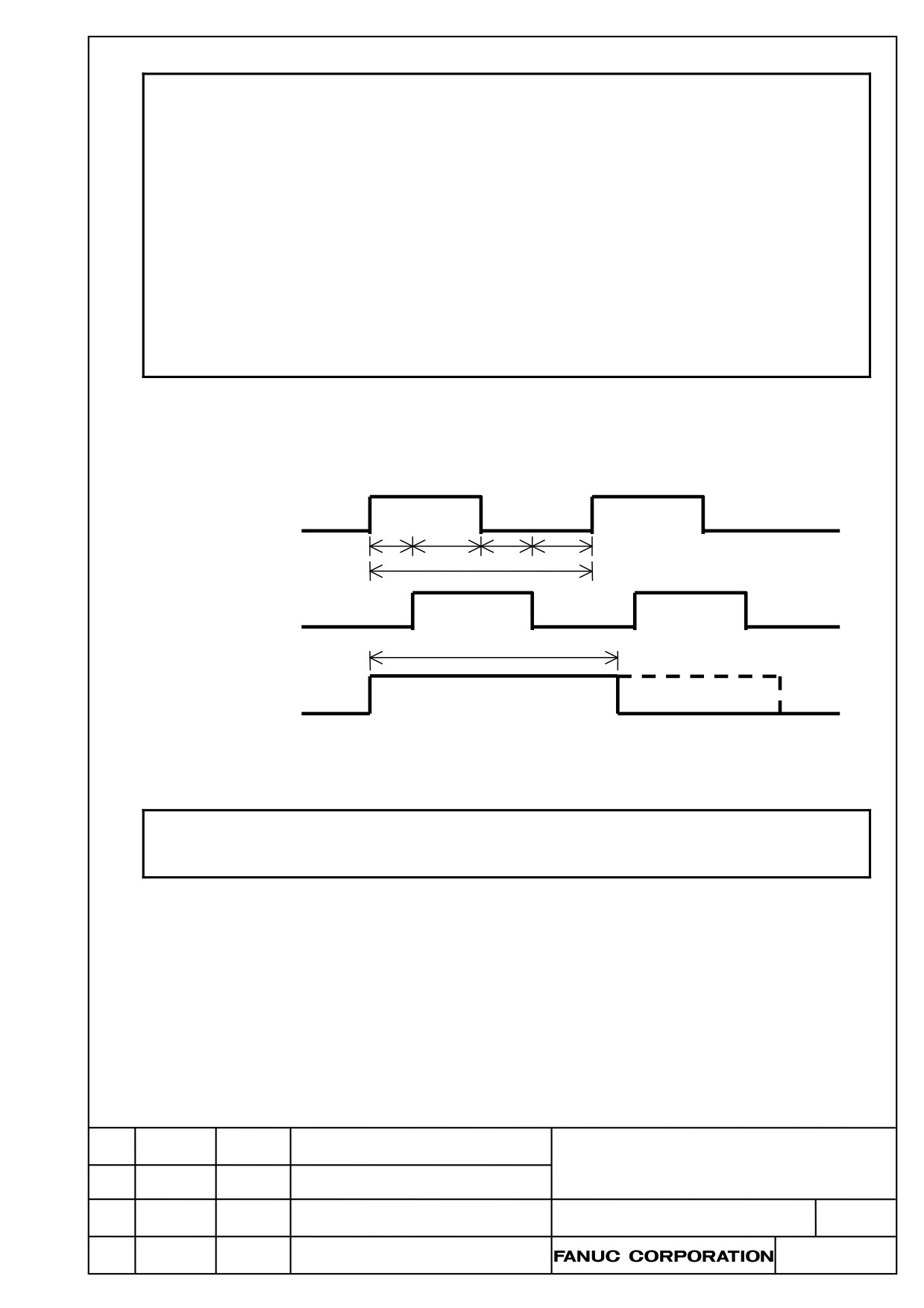
The position coder generates rectangular wave voltage signals in proportion to the angle of rotation of the
spindle, and is used in feed per revolution and thread cutting.
The figure below shows the timing of the signals generated by the pulse coder.
PCA
Td
Td
Td
Td
Tp
PCB
Tw
PCZ
1 pulses/rotation
Rectangular wave of position coder
NOTE
The differential signal is used as the feedback signal from the position coder.
*PCA, *PCB and *PCZ refer to each of their inverted signals.
Time rules
These are the signal rules that apply to the input pin of the input connector of the control unit in the figure
above.
Because the signal of this connector is in phases A and B and is a differential input, Td is of interest, which
is the duration from point A when the relative potential difference between PCA and *PCA becomes 0.5V
or higher to point B when the relative potential difference between PCB and *PCB reduces below 0.5V. Its
minimum is:
Td ≥ 0.65μs
Tp, which is the minimum of one period in each of phases A and B, is:
Tp ≥ 4μs
TITLE
DRAW. NO
CUST.
B-64303EN/03-06
Edit.
DATE
Design
Description
SHEET
5/ 7
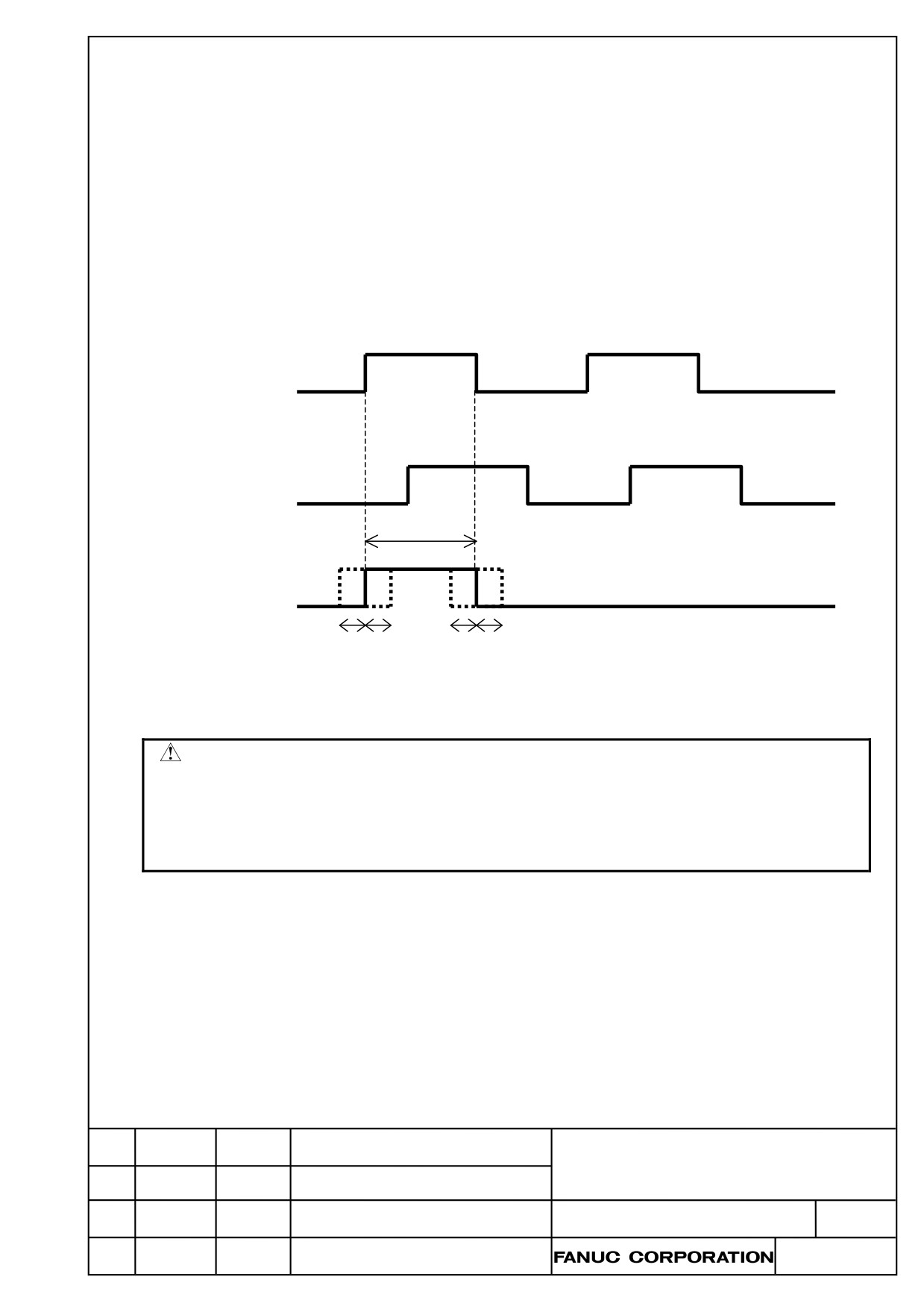
Tw, which is the minimum of the phase Z siginal (one-rotation signal) width, is:
Tw ≥ One period of the phase A or B signal
Time rules for digital encoder
The encoder has two types of analog and digital. Digital type encoder outputs A,B and Z phase signals
synchronized to internal clock of the encoder and Td is always longer than regulated value. In contrast, the
period of A, B and Z phase signals of analog type encoder may be as short as possible depending on the
revolution of the encoder.
In the digital type encoder, because the timing between Z and A or B signal can be defined, the following
time rule can be applied. Time rules for A and B phase signals are same as above.
Tw ≥ 1/2 period of the phase A or B signal
(In this regard, Tj, which is phase difference between phase A or B signal and phase Z signal, should
be within 100ns)
PCA
PCB
Tw
PCZ
1 pulse/rotation
Tj Tj
Tj Tj
Rectangular wave of position coder
WARNING
The maximum rotation speed of the position coder can be determined in
accordance with these timing rules. However, even if the rotational speed of the
position coder is lower than the maximum rotational speed, if Td not met the timing
rule because of the spindle axis vibration so on CNC can not receive the signals
from the position coder and it may cause the missing of the spindle position.
Input voltage requirements
The voltage of the A and B phase signals must meet the following requirements:
High level: 2.4 V or more
Low level: 0.8 V or less
The relative potential difference of A, B and Z phase signal should be 0.5V or more.
TITLE
DRAW. NO
CUST.
B-64303EN/03-06
Edit.
DATE
Design
Description
SHEET
6/ 7
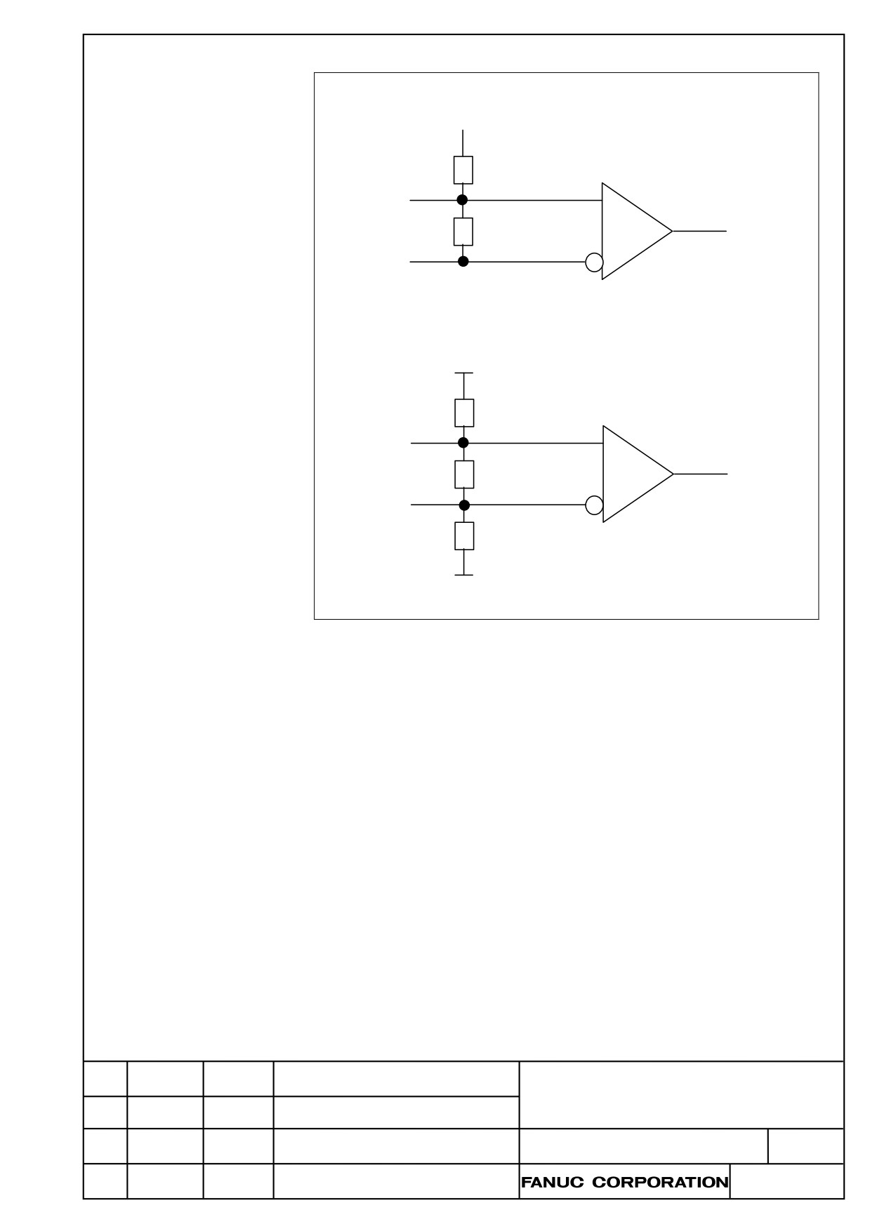
Receiver circuit
<A-phase, B-phase>
5V
560Ω
PCA / PCB
110Ω
*PCA / *PCB
<Z-phase>
5V
680Ω
PCZ
150Ω
*PCZ
680Ω
0V
TITLE
DRAW. NO
CUST.
B-64303EN/03-06
Edit.
DATE
Design
Description
SHEET
7/ 7