FANUC Series 0i-MODEL D, Series 0i Mate-MODEL D. CONNECTION MANUAL (HARDWARE) - page 15
A.EXTERNAL DIMENSIONS
B-64303EN/03
APPENDIX
OF EACH UNIT
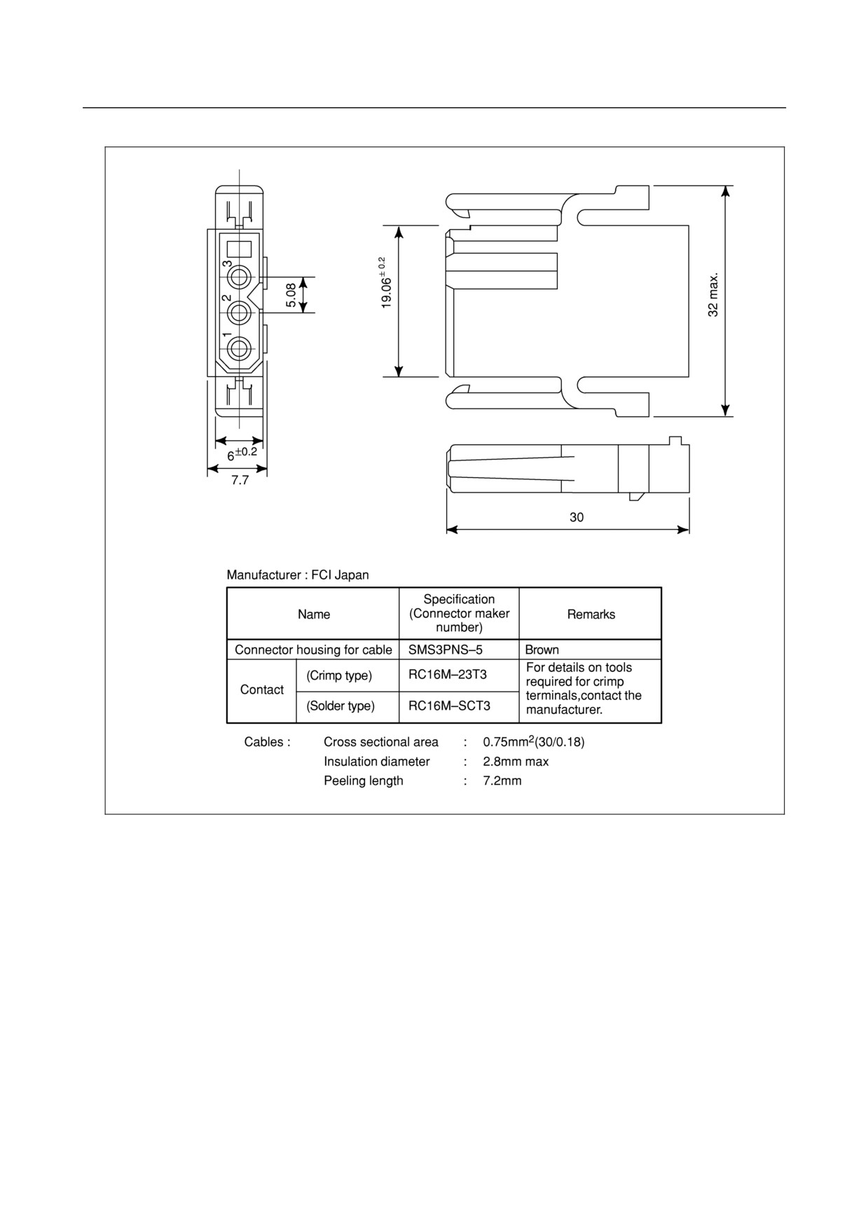
Fig. C5
Connector made by FCI Japan (3 pins,black)
- 407 -
A. EXTERNAL DIMENSIONS
OF EACH UNITTABLE
APPENDIX
B-64303EN/03
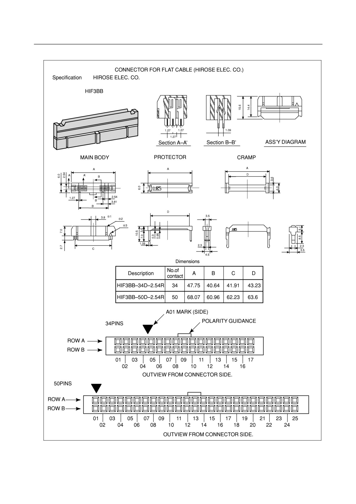
Fig. C6
Connector for HIROSE Flat cable
- 408 -
A.EXTERNAL DIMENSIONS
B-64303EN/03
APPENDIX
OF EACH UNIT
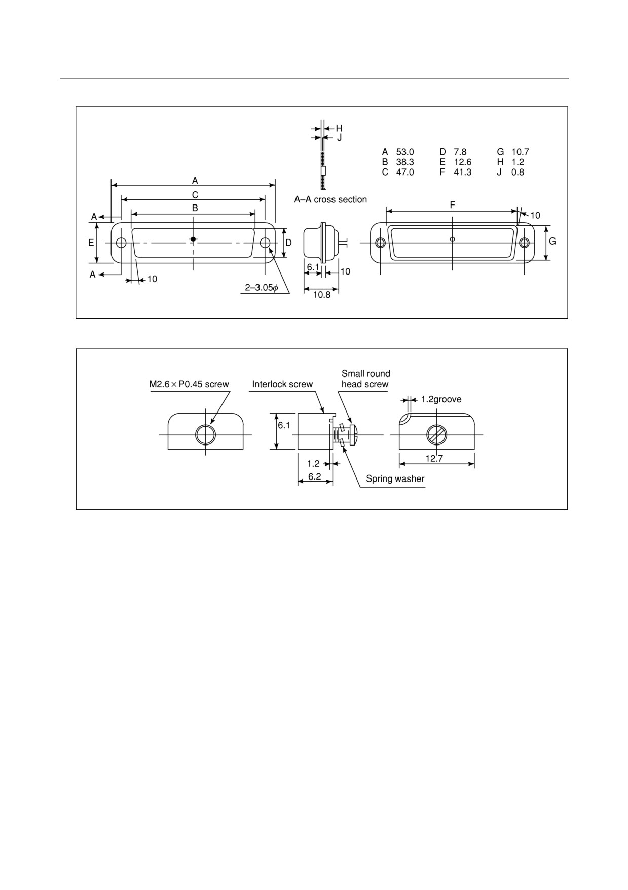
Fig. C8 (a) Punch panel connector for reader/puncher interface
Fig. C8 (b) Locking plate plate for reader/puncher interface connector
- 409 -
A. EXTERNAL DIMENSIONS
OF EACH UNITTABLE
APPENDIX
B-64303EN/03
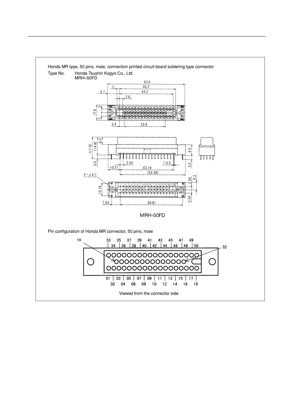
Fig. C9
Honda connector (for the distributed I/O connector printed circuit
board)
- 410 -
B.20-PIN INTERFACE
B-64303EN/03
APPENDIX
CONNECTORS AND CABLES
B
20-PIN INTERFACE CONNECTORS AND
CABLES
B.1 BOARD-MOUNTED CONNECTORS
B.1.1 Vertical-type Connectors
Models: PCR-EV20MDT (Honda Tsushin)
52618-2011 (Molex Japan)
These board-mounted connectors have been specially developed to achieve the high packing density
required for FANUC products. As explained in the following subsection, Honda PCR series connectors
can be used as cable connectors because the mating mechanism of the newly developed connectors is
compatible with that of the Honda PCR series connectors. To support this specification extensively,
many connector manufacturers are now developing custom-tailored cable connectors.
(Note that these
cables cannot be used with screw-fixing cable connector housings.)
B.1.2 Straight and Right-angled Connectors (for Spring and
Screw-fixing Connector Housings)
Models: FI80-20P (HIROSE) (straight connector)
DF1R020WB1 (JAE) (straight connector)
PCR-E20LMDETZ-SL (Honda Tsushin) (right-angled connector)
These connectors are used for the main and option boards. As cable connectors, they are compatible
with screw-fixing connector housings as well as the spring locking connector housings.
B.2 CABLE CONNECTORS
Models: Hirose Electric: FI80-20P (straight connector)
Japan Aviation Electronics Industry: DF1R020WB1 (straight connector)
Honda Tsushin: PCR-E20LMDETZ-SL (right-angled connector)
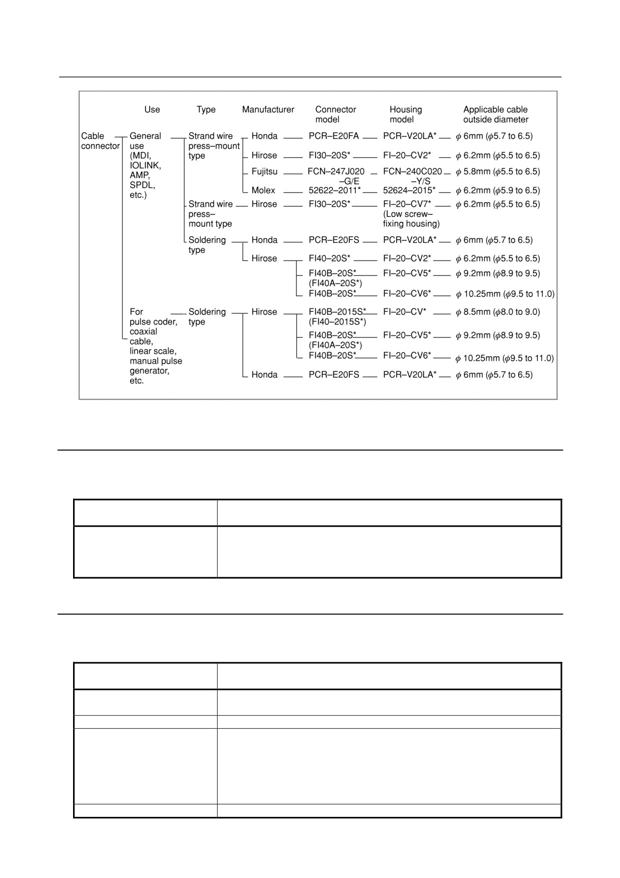
Cable connectors consist of a connector main body and housing. The models listed below are available.
Those connectors not marked with an asterisk are currently being mass-produced as manufacturer's
standard models. Those marked with an asterisk are produced according to custom specifications by
FANUC.
- 411 -
B. 20-PIN INTERFACE
CONNECTORS AND CABLES
APPENDIX
B-64303EN/03
Fig. B.2 Cable connectors
B.2.1 Strand Wire Press-mount Connector
With this connector, #28AWG wires are press-connected to each pin at the same time. The cost of
producing a cable/connector assembly with this connector model is much lower than with connectors
designed for crimping or soldering.
Connector model
Supplementary description
(manufacturer)
FI-20-CV7 (Hirose)
Small and low-profile case. This connector is fixed to the board-mounted
connector with screws. This connector can be connected to the board-mounted
connector on the main board of the LCD-mounted type, but cannot be connected
to the board-mounted connector on the main board of the stand-alone type.
B.2.2 Soldering Type Connector
Details of soldering type connectors and their housings are summarized below.
Table B.2 Details of soldering type connectors and housings
Connector model
Supplementary description
(manufacturer)
PCR-E20FS (Honda)
Soldering type connector for general signals. This is suitable for producing
cable assemblies in small quantities, as well as on-site.
FI40-20S (Hirose)
Equivalent to Honda PCR-E20FS
FI40B-20S (Hirose)
Has the same number of pins as the FI40-20S, but features a wider soldering
(formerly, FI40A-20S)
pitch, facilitating soldering and enabling the use of thicker wires. Its reinforced
pins allow wires as thick as #17AWG to be soldered to the FI40B-20S (wires no
thicker than #20AWG can be used with the FI40A-20S). Note, however, that a
thick wire, such as #17AWG, should be used with a more robust housing like the
FI-20-CV6.
FI40B-2015S (Hirose)
Features a wider soldering pitch, attained by using the space provided by thinning
- 412 -
B.20-PIN INTERFACE
B-64303EN/03
APPENDIX
CONNECTORS AND CABLES
Connector model
Supplementary description
(manufacturer)
(formerly, FI40-2015S)
out some pins. Also features tougher pins, compared with its predecessor, the
FI40-2015S. These pins can be soldered to wires as thick as #17AWG,
provided that the cable diameter does not exceed 8.5 mm.
Housing model (manufacturer)
Supplementary description
FI-20-CV5 (Hirose)
Should be used with the FI40B-20S. This is a plastic housing designed for use
with a cable that is 9.2 mm in diameter.
FI-20-CV6 (Hirose)
Should be used with the FI40B-20S. This housing, however, can be used with a
thicker cable (such as 10.25 mm) than is possible with the FI-20-CV5. Its
components are die cast.
In addition to the combinations shown in Fig. B.2, Hirose soldering-type connectors can be combined
with the housings listed below. Ensure that the diameter of the cable used with each housing satisfies
the requirements of that housing.
Connector model
Housing model (applicable cable diameter)
FI40B-2015S
⇔
FI-20-CV (8.5 mm in diameter) only
(formerly FI40-2015S)
FI40-20S
FI-20-CV2 (φ6.2mm)
FI40B-20S
⇔
FI-20-CV5 (φ9.2mm)
(formerly FI40A-20S)
FI-20-CV6 (φ10.25mm)
Those listed on the left can be used.
B.3 RECOMMENDED CONNECTORS, APPLICABLE
HOUSINGS, AND CABLES
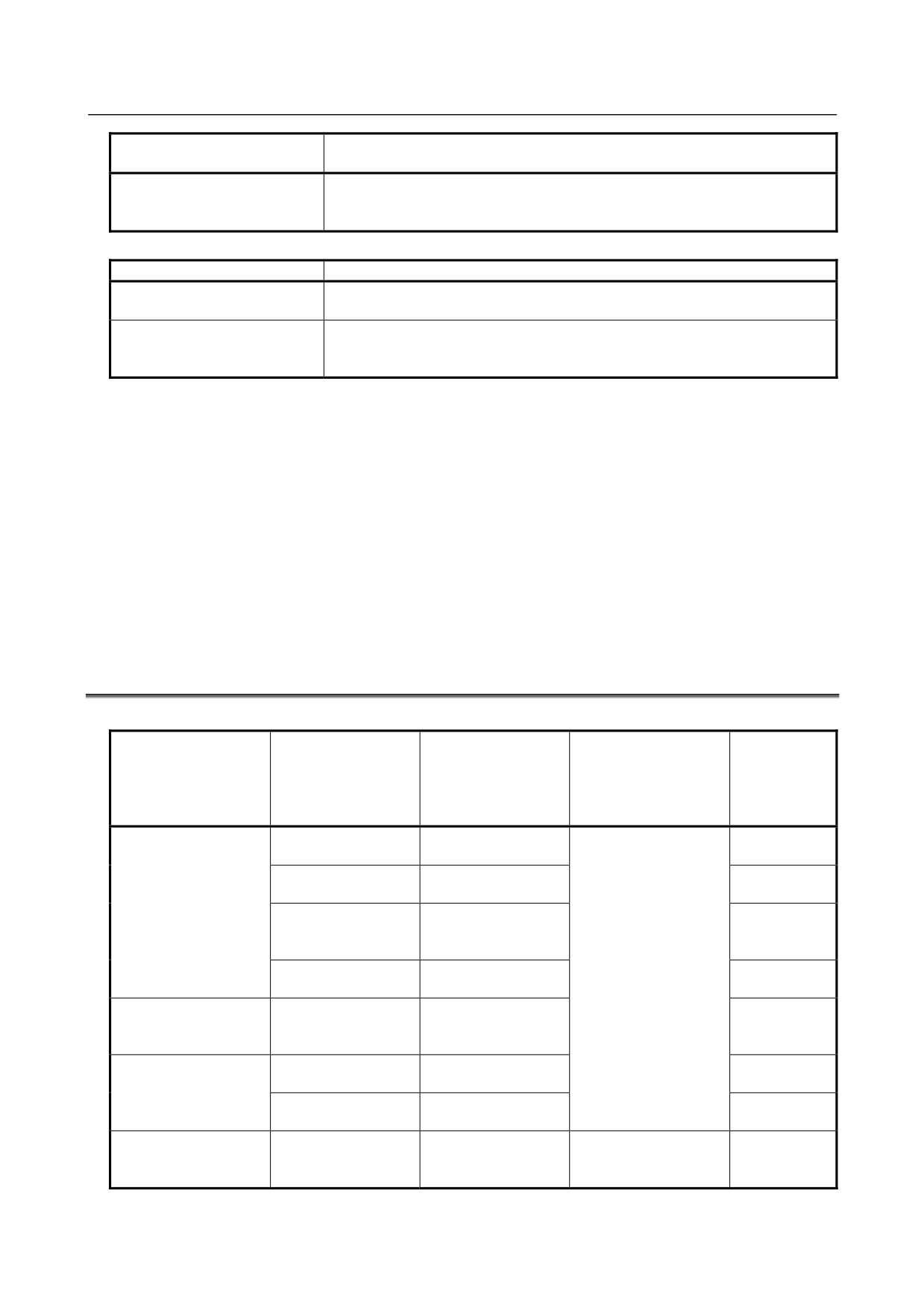
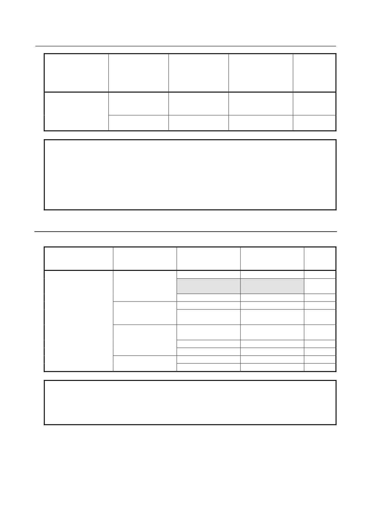
Table B.3 Recommended connectors, applicable housings, and cables
Compatible
Connector name
FANUC-approved
FANUC-approved
cable(cable diameter)
referenced in the
connector(manufact
housing
FANUC development
Remark
Connection Manual
urer)
(manufacturer)
FANUC specification
number
PCR-E20FA
PCR-V20LA(Honda
Plastic housing
(Honda Tsushin)
Tsushin)
FI30-20S
FI-20-CV2(Hirose
Metal housing
PCR-E20FA
(Hirose Electric)
Electric)
Strand wire
FCN-247J020-G/E
FCN-240C020-Y/S
press-mount type
(FUJITSU
(FUJITSU
Plastic housing
COMPONENT)
COMPONENT)
52622-2011
A66L-0001-0284#10P
52624-2015(Molex)
Plastic housing
(Molex)
(6.2 mm in diameter)
PCR-E20FA
FI30-20S
FI-20-CV7
Strand wire
Plastic housing
(Hirose Electric)
(Hirose Electric)
press-mount type
PCR-E20FS
PCR-V20LA
Plastic housing
PCR-E20FS
(Honda Tsushin)
(Honda Tsushin)
Soldering type
FI40-20S
FI-20-CV2
Plastic housing
(Hirose Electric)
(Hirose Electric)
FI40B-2015S
FI40B-2015S
A66L-0001-0286(Note)
FI-20-CV
(formerly FI40-2015S)
(formerly FI40-2015S)
A66L-0001-0402(Note)
Plastic housing
(Hirose Electric)
15-pin soldering type
(Hirose Electric)
(8.5 mm in diameter)
- 413 -
B. 20-PIN INTERFACE
CONNECTORS AND CABLES
APPENDIX
B-64303EN/03
Compatible
Connector name
FANUC-approved
FANUC-approved
cable(cable diameter)
referenced in the
connector(manufact
housing
FANUC development
Remark
Connection Manual
urer)
(manufacturer)
FANUC specification
number
FI40B-20S
A66L-0001-0367
FI-20-CV5
FI40B-20S
(formerly FI40A-205)
A66L-0001-0368
Plastic housing
(Hirose Electric)
(formerly FI40A-2015S)
(Hirose Electric)
(9.2 mm in diameter)
Soldering type
FI40B-20S
FI-20-CV6
A66L-0001-0403(Note)
Metal housing
(Hirose Electric)
(Hirose Electric)
(9.8 mm in diameter)
NOTE
Cable A66L-0001-0286 has been recommended for use as a pulse coder cable.
It can be up to 20 m long. Two cables, A66L-0001-0402 and A66L-0001-0403,
have recently been developed. A66L-0001-0402 and A66L-0001-0403 can be
as long as 30 m and 50 m, respectively.
(See Fig. 2 for detailed specifications.)
Both cables have the same level of oil and bending resistance (cable, 100 mm in
diameter, capable of withstanding at least 10 million bending cycles) as
conventional cables, and are UL- and CSA-certified.
B.3.1 Recommended Connectors
Press-mount type connector assembly tools and jigs
Connector model
FANUC-approved
referenced in the
connector
Wire forming tool
Press-mounting tool
Remark
Connection Manual
(manufacturer)
PCR-E20FA
PCR-E20FA
PCS-K2A
FHPT-918A
Low cost
(Honda Tsushin)
JGPS-015-1/1-20
MFC-K1
(Note 1)
JGPS-014
PCS-K1
FHAT-918A
FI30-20S
FI30-20CAT
FI30-20/ID
Low cost
(Hirose Electric)
FI30-20CAT1
HHP-502
FI30-20GP
FCN-247J020-G/S
FCN-237T-T043/H
FCN-237T-T109/H
(Fujitsu)
FCN-247T-T066/H
FCN-237T-T044/H
FCN-237T-T062/H
52622-2011
57829-5000
57830-5000
Low cost
(Molex)
57823-5000
57824-5000
NOTE
1 Those tools indicated by shading are available from FANUC (specification
number A02B-0120-K391).
2 The tools available from each manufacturer are specifically designed for use with
the connectors manufactured by that manufacturer.
- 414 -
B.20-PIN INTERFACE
B-64303EN/03
APPENDIX
CONNECTORS AND CABLES
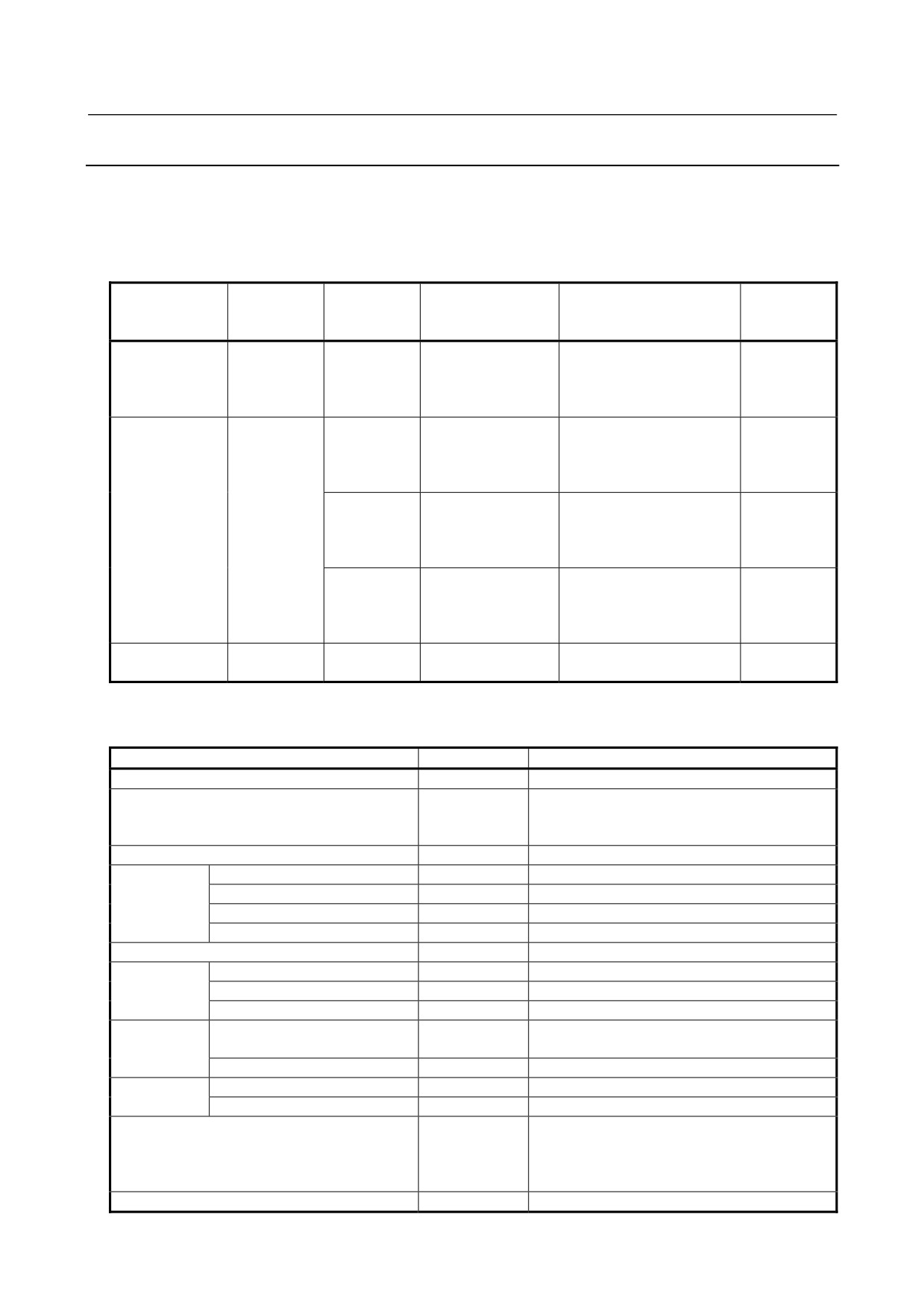
B.3.2 Applicable Cables
Materials for cable assemblies
Machine tool builders are required to manufacture or procure the materials for the cable assemblies to be
used with their products. FANUC recommends the following materials as being suitable for interface
connectors. Individual machine tool builders are encouraged to contact each cable manufacturer for
themselves, as required.
FANUC
Material
Use
Constitution
specification
Manufacturer
Remark
number
10-pair cable
General use
0.08mm2
A66L-0001-0284
Hitachi Cable, Ltd.
10-pair
#10P
Oki Electric Cable Co., Ltd.
SHINKO ELECTRIC
INDUSTRIES CO., LTD.
12-conductor
Pulse coder,
0.5mm2
A66L-0001-0286
Hitachi Cable, Ltd.
20 m or less
composite cable
linear scale,
6-conductor
Oki Electric Cable Co., Ltd.
manual pulse
0.18mm2
SHINKO ELECTRIC
generator
3-pair
INDUSTRIES CO., LTD.
0.75mm2
A66L-0001-0402
Oki Electric Cable Co., Ltd.
30 m or less
6-conductor
Usable on
0.18mm2
movable
3-pair
parts
1.25mm2
A66L-0001-0403
Oki Electric Cable Co., Ltd.
50 m or less
6-conductor
Usable on
0.18mm2
movable
3-pair
parts
5-core coaxial
CRT interface
5-conductor
A66L-0001-0371
Hitachi Cable, Ltd.
50 m or less
cable
coaxial
10-pair cable
(a) Specifications
Item
Unit
Specifications
Product No.
-
A66L-0001-0284#10P
Manufacturer
-
Hitachi Cable,Ltd.
Oki Electric Cable, Co.,Ltd.
SHINKO ELECTRIC INDUSTRIES CO., LTD.
Rating
-
80°C 30V : UL20276
Material
Conductor
-
Stranded wire of tinned annealed copper
Insulator
-
Vinyl
Shield braid
-
Tinned annealed copper wire
Sheath
-
Heat-resistant oilproof vinyl
Number of pairs
Pairs
10
Conductor
Size
AWG
28
Structure
Conductors/mm
7/0.127
Outside diameter
mm
0.38
Insulator
Thickness
mm
0.1
Thinnest portion : 0.8 (3.1mm)
Outside diameter (approx.)
mm
0.58
Twisted pair
Outside diameter (approx.)
mm
1.16
Pitch
mm
20 or less
Lay
-
Collect the required number of twisted pairs into
a cable, then wrap binding tape around the
cable. To make the cable round, apply a cable
separator as required.
Lay diameter (approx.)
mm
3.5
- 415 -
B. 20-PIN INTERFACE
CONNECTORS AND CABLES
APPENDIX
B-64303EN/03
Item
Unit
Specifications
Drain wire
Conductors/mm
Hitachi Cable : Not available
Oki Electric Cable : Available,10/0.12
SHINKO ELECTRIC INDUSTRIES CO., LTD. :
Not available
Shield braid
Element wire diameter
mm
0.12
Braid density
%
85 or more
Sheath
Color
-
Black
Thickness
mm
1.0
Outside diameter (approx.)
mm
6.2
Standard length
m
200
Packing method
-
Bundle
Electrical
Electric resistance (at 20°C )
Ω/km
233 or less
performance
Insulation resistance (at 20°C )
MΩ-km
10 or less
Dielectric strength (AC)
V/min.
300
Flame resistance
-
Shall pass flame resistance test VW-1SC of UL
standards.
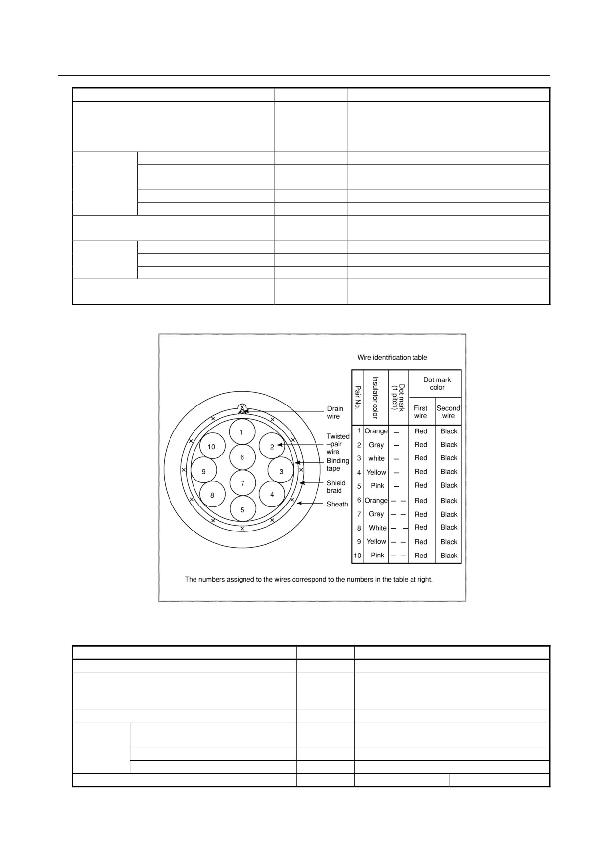
(b) Structure drawing
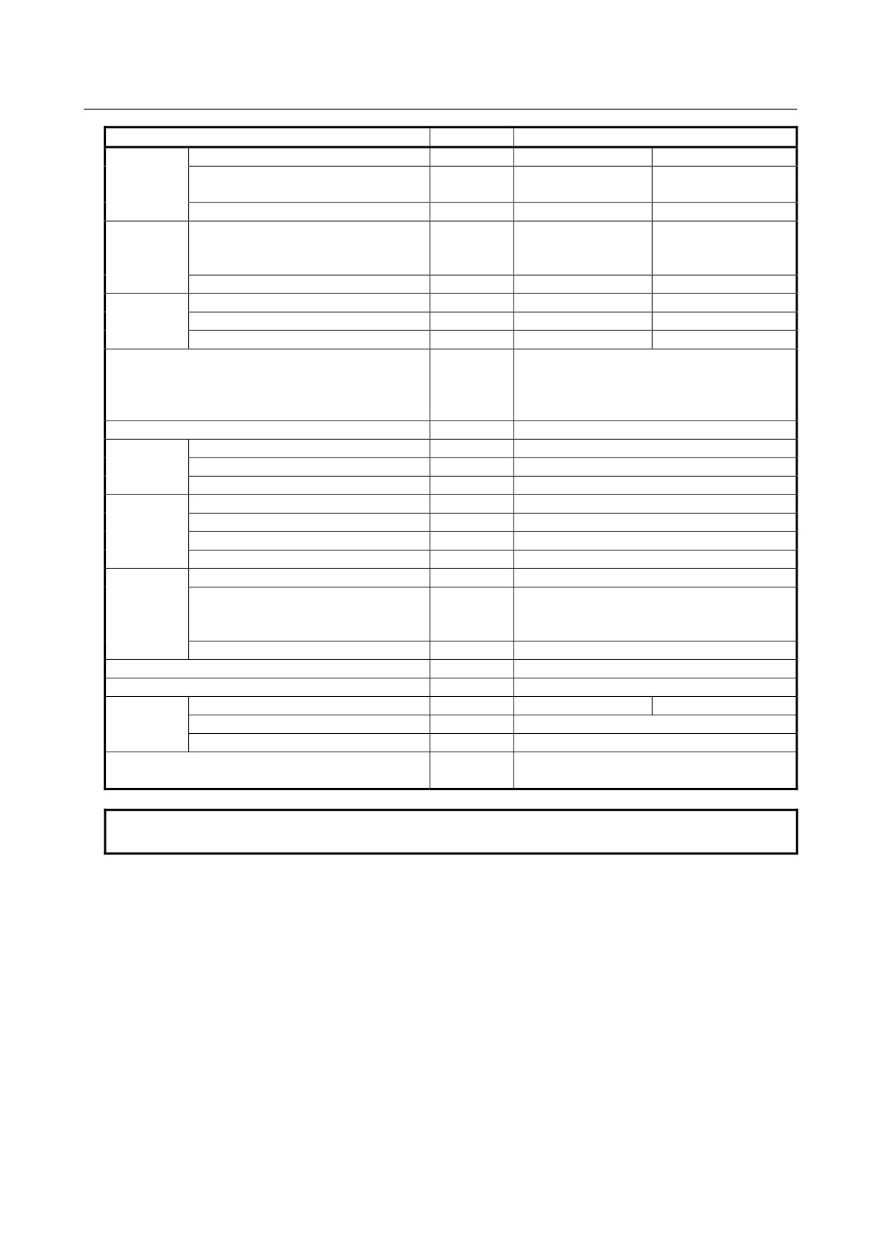
Composite 12-core cable
(a) Specifications
Item
Unit
Specifications
Product No.
-
A66L-0001-0286
Manufacturer
-
Hitachi Electric Cable Co., Ltd.
Oki Cable, Ltd.
SHINKO ELECTRIC INDUSTRIES CO., LTD.
Rating
-
80°C, 30V
Material
Conductor,braid-shielded wire,drain
-
Strand wire of tinned annealed
wire
Insulator
-
Heat-resistant flame-retardant vinyl
Sheath
-
Oilproof, heat-resistant, flame-retardant vinyl
Number of wires (wire ons.)
Cores
6 (1 to 6)
6 (three pairs) (7 to 9)
- 416 -
B.20-PIN INTERFACE
B-64303EN/03
APPENDIX
CONNECTORS AND CABLES
Item
Unit
Specifications
Conductor
Size
mm2
0.5
0.18
Structure
Conductors/
20/0.18
7/0.18
mm
Outside diameter
mm
0.94
0.54
Insulator
Standard thickness (The minimum
mm
0.25
0.2
thickness is at least 80% of the
standard thickness.)
Outside diameter
mm
1.50
0.94
Twisted pair
Outside diameter
mm
1.88
Direction of lay
-
Left
Pitch
mm
20 or less
Lay
-
Twist the wires at an appropriate pitch so the
outermost layer is right-twisted, and wrap tape
around the outermost layer. Apply a cable
separator as required.
Lay diameter (approx.)
mm
5.7
Drain wire
Size
mm2
0.3
Structure
Wires/mm
12/0.18
Outside diameter
mm
0.72
Shield braid
Element wire diameter
mm
0.12
Thickness
mm
0.3
Braid density
%
70
Outside diameter
mm
6.3
Sheath
Color
-
Black
Standard thickness (The minimum
mm
1.1
thickness is at least 85% of the
standard thickness.)
Outside diameter
mm
8.5Max. 9.0 (Note)
Standard length
m
100
Packing method
-
Bundle
Electrical
Electric resistance (at 20°C) (wire nos.)
Ω/km
39.4 (1 to 6)
113 (7 to 9)
performance
Insulation resistance (at 20°C)
MΩ-km
15
Dielectric strength (AC)
V/min.
500
Flame resistance
-
Shall pass flame resistance test VW-1SC of
UL standards.
NOTE
The maximum outside diameter applies to portions other than the drain wire.
- 417 -
B. 20-PIN INTERFACE
CONNECTORS AND CABLES
APPENDIX
B-64303EN/03
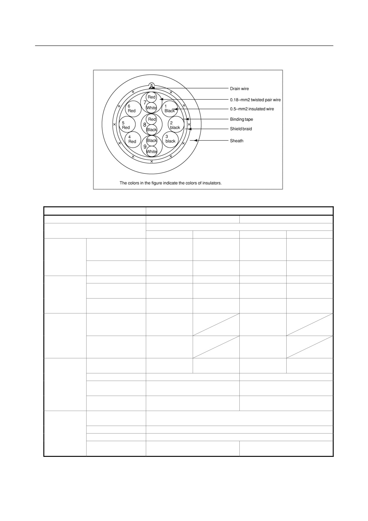
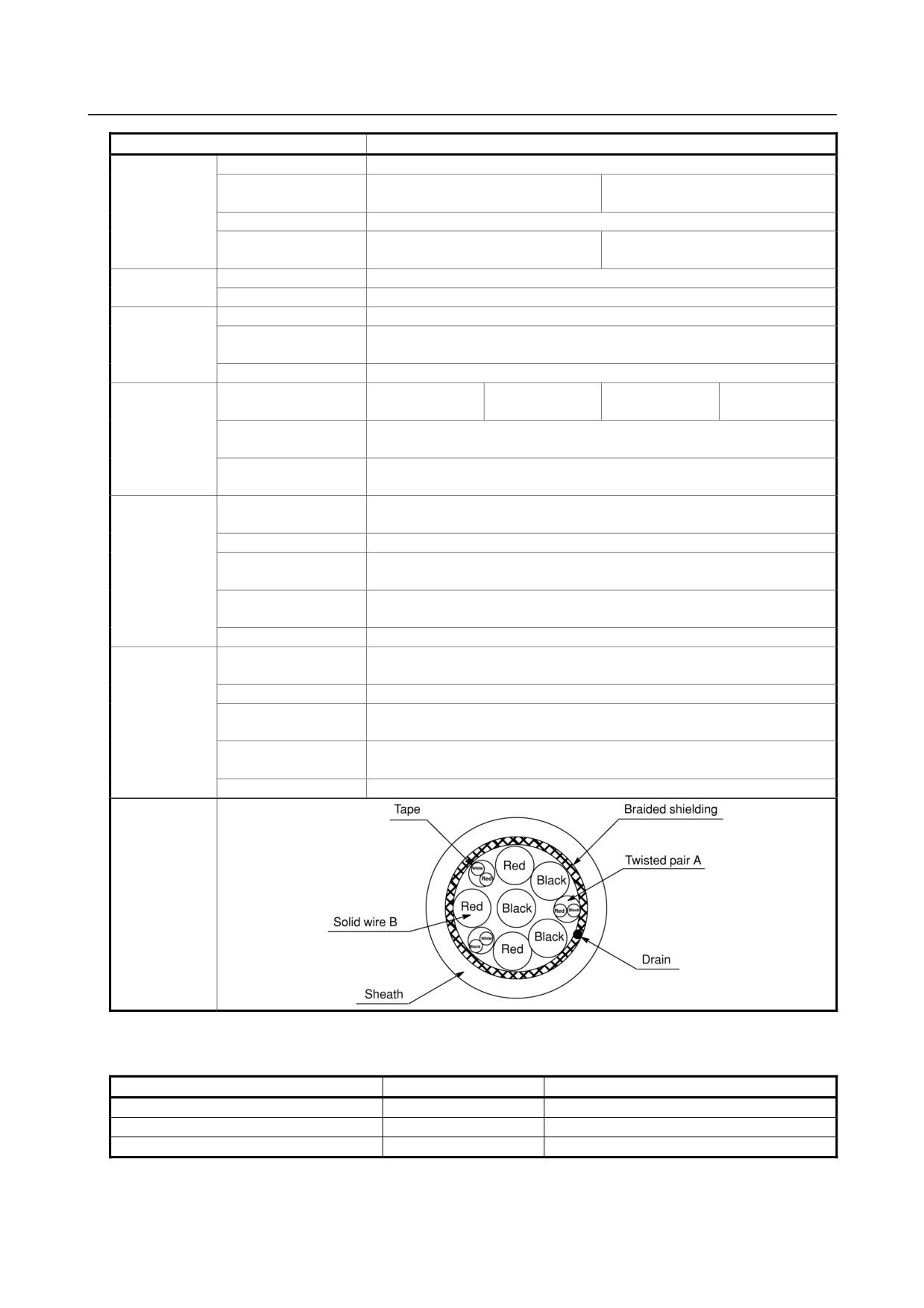
(b) Cable structure
The cable structure is shown below.
(c) Specifications
Item
Specification
FANUC specification number
A66L-0001-0402
A66L-0001-0403
Manufacturer
Oki Electric Cable Co., Ltd.
A-conductor
B-conductor
A-conductor
B-conductor
Conductor
Constitution
16/0.12
3/22/0.12
16/0.12
7/16/0.12
Number of
(0.18mm2)
(0.75mm2)
(0.18mm2)
(1.25mm2)
conductors/ mm
Typical outside
0.55
1.20
0.55
1.70
diameter (mm)
Insulation
Color
White, red, black
Red, black
White, red, black
Red, black
(polyester)
Typical thickness
0.16
0.23
0.16
0.25
(mm)
Typical outside
0.87
1.66
0.87
2.20
diameter (mm)
Pair twisting
Constitution
White-red,
White-red,
white-black, and
white-black, and
black-red
black-red
Direction of twisting
Left
Left
Typical pitch: 20
Typical pitch: 20
mm
mm
Assembling by
Number of strands or
3
6
3
6
twisting
conductors
Direction of twisting
Left
Left
Taping
Twisting is wrapped with washi, or
Twisting is wrapped with washi, or
Japanese paper, tape.
Japanese paper, tape.
Typical outside
5.7
6.9
diameter (mm)
Braided
Typical strand
0.14
shielding
diameter (mm)
Typical density (mm)
80
Drain
A 12/0.18 mm wire is roughly wrapped under braided shielding.
Typical outside
6.4
7.6
diameter (mm)
- 418 -
B.20-PIN INTERFACE
B-64303EN/03
APPENDIX
CONNECTORS AND CABLES
Item
Specification
Sheath
Color
Black (matted)
(polyurethane)
Typical thickness
1.05
1.1
(mm)
Vertical taping
Vertically taped with washi under sheathing.
Outside diameter
8.5±0.3
9.8±0.3
(mm)
Finished
Typical length (m)
100
assembly
Short size
Basically not approved.
Finished
Rating
80°C 30V
assembly
Standard
Shall comply with UL STYLE 20236 and CSA LL43109 AWM I/II A 80°C
performance
30V FT-1.
Flame resistance
Shall comply with VW-1 and FT-1.
Electrical
Conductor resistance
103 or lower
25.5 or lower
103 or lower
15.0 or lower
performance
Ω/km (20°C)
Insulation resistance
1 or higher
MΩ/km (20°C)
Dielectric strength
A.C 500
V-min
Insulation
Tensile strength
9.8 or higher
performance
N/mm2
Elongation
%
100 or higher
Tensile strength after
At least 70% of that before aging
aging
%
Elongation after
At least 65% of that before aging
aging
%
Aging condition
For 168 hours at 113°C
Sheathing
Tensile strength
9.8 or higher
performance
N/mm2
Elongation
%
100 or higher
Tensile strength after
At least 70% of that before aging
aging
%
Elongation after
At least 65% of that before aging
aging
%
Aging condition
For 168 hours at 113°C
Cable cross
section
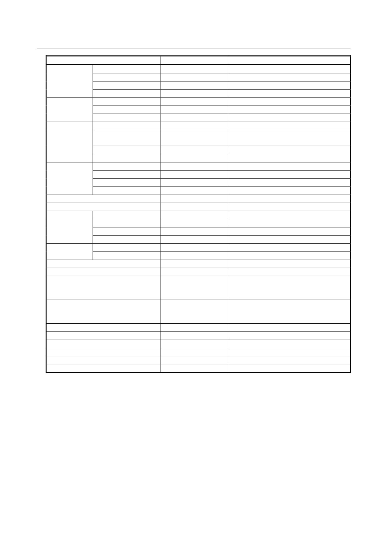
5-core coaxial cable
(a) Specifications
Item
Unit
Description
Specification
-
A66L-0001-0371
Manufacture
-
HITACHI CABLE CO., LTD.
Number of Conductors
Core
5
- 419 -
B. 20-PIN INTERFACE
CONNECTORS AND CABLES
APPENDIX
B-64303EN/03
Item
Unit
Description
Inside
Size
mm2
0.14
Conductor
Components
Conductors(PCS)/mm
7/0.16
Material
-
Tin-coated Soft Copper Wire
Diameter (approx.)
mm
0.48
Insulator
Material (Color)
-
Polyethylene (White), heat-resistant 80°C
Thickness
mm
0.71
Diameter (approx.)
mm
1.90
Outside
Material
-
Tin-coated Soft Copper Wire (Rolled)
Conductor
Diameter of
mm
0.08
Component-Wire
Density
%
95 or more
Thickness
mm
0.2
Jacket
Material
-
Vinyl, heat-resistant 80°C
Color
-
Black. White. Red. Green. Blue
Thickness
mm
0.15
Diameter (approx.)
mm
2.6
Twisted Assembly Diameter (approx.)
mm
7.1
Thickness of Paper Tape
mm
0.05
Shield braid
Wire dia. Material
mm
0.12 (Tin-coaded soft copper wire)
Density
%
80 or more (typ 82%)
Thickness
mm
0.3
Diameter
mm
7.8
Sheath
Material, Color
-
Oil Tight Vinyl (A), Black, heat-resistant 80°C
Thickness
mm
0.7 (Min. thickness: 0.56)
Finish Diameter
mm
9.2±0.3
Conductor Resistance (20°C)
Ω/km
143 or less
Dielectric strength
-
1000 VAC must be withstood for one minute.
(between internal conductor and external
conductor)
Insulation resistance
MΩ-km
1000 or more
(between internal conductor and external
conductor, 20°C)
Impedance (10MHz)
Ω
75±5
Standard Capacitance (1MHz)
nF/km
56
Standard Attention
dB/km
53
Weight
kg/km
105
Standard Length
m
200
Package form
-
Bundle
- 420 -
B.20-PIN INTERFACE
B-64303EN/03
APPENDIX
CONNECTORS AND CABLES
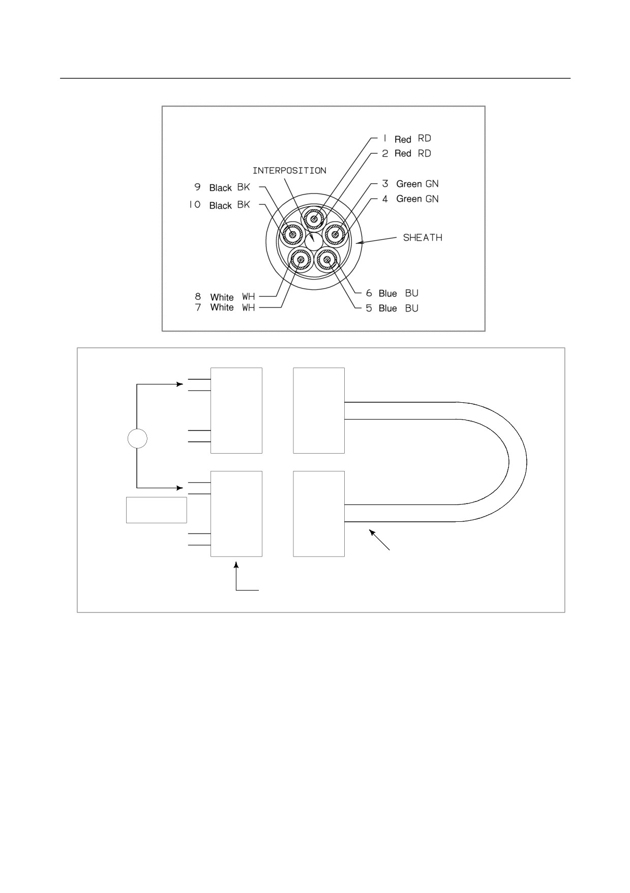
An example of circuit testing 20-pin interface cable
⋅
⋅
⋅
Ω
Resistor
Check every
⋅
pin
⋅
⋅
Cable (20-pin interface connector)
PCB connector
PCR-E20LMD-SL (Honda)
Available from general manufacturers
- 421 -
C. CONNECTION CABLE
(SUPPLIED FROM US)
APPENDIX
B-64303EN/03
C CONNECTION CABLE (SUPPLIED FROM
US)
Maximum allowable cable length between units
Maximum cable
Cable type
Use and condition
length (m)
MDI cable
Control unit-to-MDI unit
20m
Electrical cable
10m (Note 2)
I/O Link cable
Electrical-to-optical conversion adapter
2m
Optical cable
200m
Electrical cable (control unit-to-spindle servo unit)
20m
Serial spindle cable
Electrical-to-optical conversion adapter
2m
Optical cable
200m
Position coder cable
Control unit-position coder
50m
Connector panel I/O operator's panel I/O
MPG cable
50m
module-to-manual pulse generator
FSSB cable
See APPENDIX D.
HSSB cable
See APPENDIX D.
4800 baud or less
100m
RS-232-C communication cable
9600 baud or less
50m
9600 baud or less
800m
RS-422 communication cable
19.2 k baud
50m
NOTE
1 The maximum cable lengths listed above apply only when the respective
recommended cables stated in the text are used. If a non-recommended cable
is used, the maximum cable length may not be guaranteed. Cables other than
the above are used. See the respective descriptions in this manual for details
of these cables.
2 This cable can be extended to up to 15 m if it is used within the cabinet.
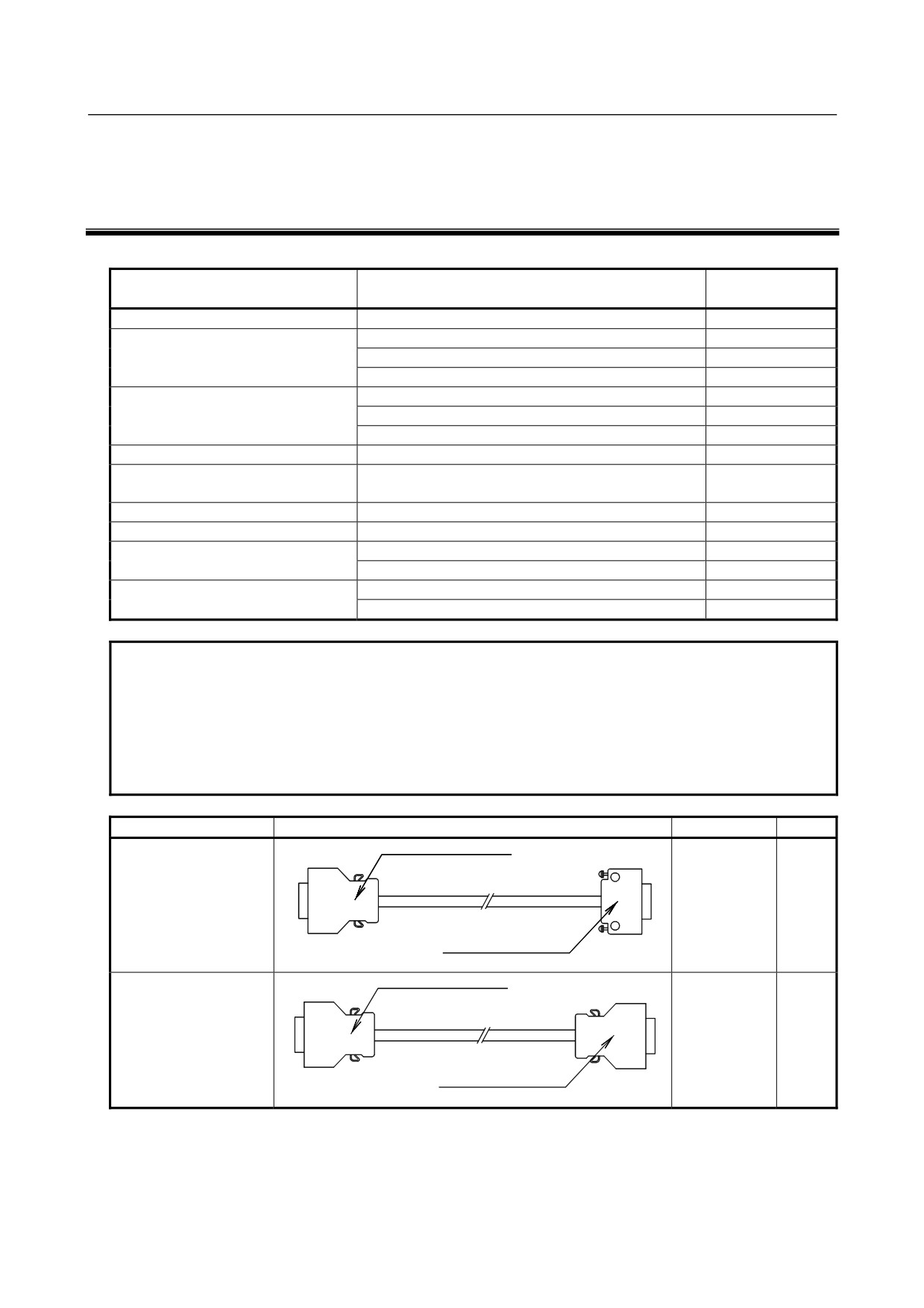
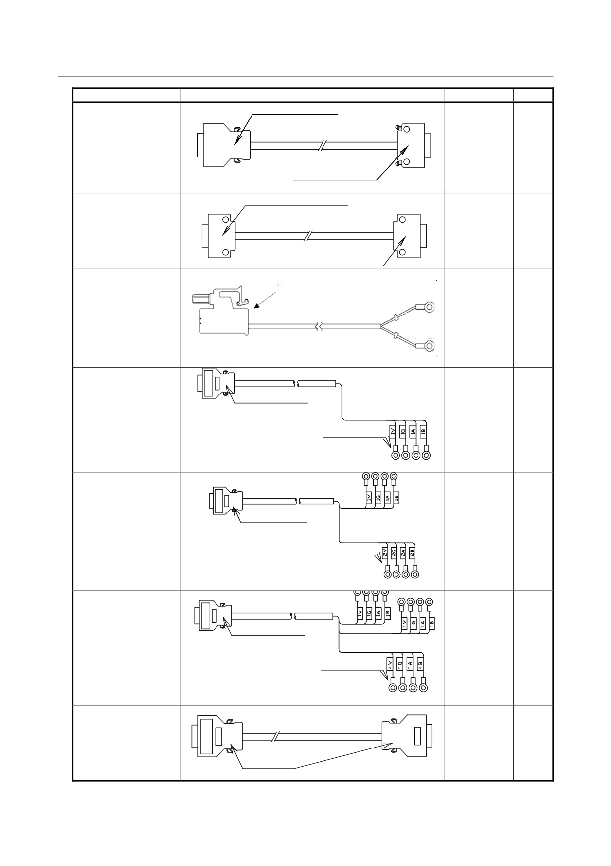
Purpose
Description
Specification
Length
PCR-E20FA
Spindle signal cable
A02B-0236-
5m
K845
FI-20-CV7
Electrical-to-electrical
PCR-E20FA
Spindle signal cable
For inter-spindle serial
A02B-0236-
5m
connection
K846
PCR-E20FA
Electrical-to-electrical
- 422 -
C.CONNECTION CABLE
B-64303EN/03
APPENDIX
(SUPPLIED FROM US)
Purpose
Description
Specification
Length
PCR-E20FA
Spindle signal cable
↑
A02B-0236-
1m
↓
K847
FI-20-CV7
For optical adapter
MDI signal cable
PCR-E20FA-E20SPF1A+
control unit (JA2)
↑
A02B-0309-
45cm
↓
K813
MDI unit
(CK1)
PCR-E20FA-E20SPF1A+
External installation
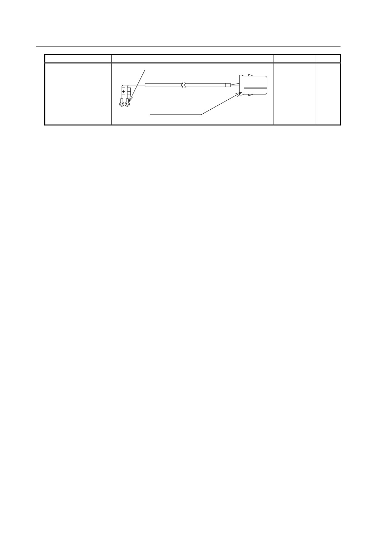
Battery connector
M4 crimp terminal
controller battery cable
(Specific to FANUC )
control unit (CA114)
↑
A02B-0309-
(+: White)
14m
↓
K103
(+: Black
External installation
controller battery
(terminal block)
Manual pulse generator
cable (for one unit)
FI40-2015S
Control unit (JA3)
A02B-0120-
7m
↑
K847
M3 crimp style terminal
↓
Manual pulse generator
terminal board
Manual pulse generator
cable (for two units)
FI40-2015S
Control unit (JA3)
A02B-0120-
7m
↑
K848
M3 crimp style terminal
↓
Manual pulse generator
terminal board
Manual pulse generator
cable (for three units)
FI40-2015S
Control unit (JA3)
A02B-0120-
7m
↑
K841
↓
M3 crimp style terminal
Manual pulse generator
terminal board
I/O Link cable
Control unit (JD1A)
A02B-0120-
5m
↑
K842
↓
PCR-E20FA
I/O unit (JD1B)
- 423 -
C. CONNECTION CABLE
(SUPPLIED FROM US)
APPENDIX
B-64303EN/03
Purpose
Description
Specification
Length
Control unit power
M3 crimp style terminal
supply cable
Stabilized power supply
A02B-0124-
5m
(24 VDC)
K830
↑
AMP1-178288-3
↓
Control unit (CP1A)
- 424 -
B-64303EN/03
APPENDIX
D.OPTICAL FIBER CABLE
D OPTICAL FIBER CABLE
Optical fiber cables for the following interfaces are available. This table lists the usable combinations.
Relay enabled
Recommended
Maximum allowable
Applicable junction
Interface
/ disabled
optical cable
transmission distance
adapter
Serial spindle interface
Disabled
A66L-6001-0026#L~
100m
*1
Enabled
A66L-6001-0029#L~
55m
*2
A63L-0020-0004
Disabled
A66L-6001-0026#L~
200m
I/O Link interface
*1
Enabled
A66L-6001-0026#L~
100m
*2
A63L-0020-0002
Disabled
A66L-6001-0023#L~
10m
Disabled
A66L-6001-0026#L~
50m
High-speed serial bus
Disabled
A66L-6001-0049#L~
100m
(HSSB) interface
Enabled
A66L-6001-0029#L~
35m
*2
A63L-0020-0004
Enabled
A66L-6001-0049#L~
55m
*2
A63L-0020-0004
Serial servo bus (FSSB)
Disabled
A66L-6001-0023#L~
10m
interface
Disabled
A66L-6001-0026#L~
50m
*3
CAUTION
1 During connection with optical fiber cables
2 To relay a connection with optical fiber cables, only one replay point is allowed.
In addition, the total length of two cables must be the maximum allowable
transmission distance or less.
3 See Subsection 7.2.2, “Interface to the Servo Amplifiers” for length restriction of
FSSB line.
• The length between the CNC and the first slave unit is 50 m or less.
• The length between slave units is 40 m or less.
• The total length including the above is 500 m or less.
Notes on the specifications of optical fiber cable
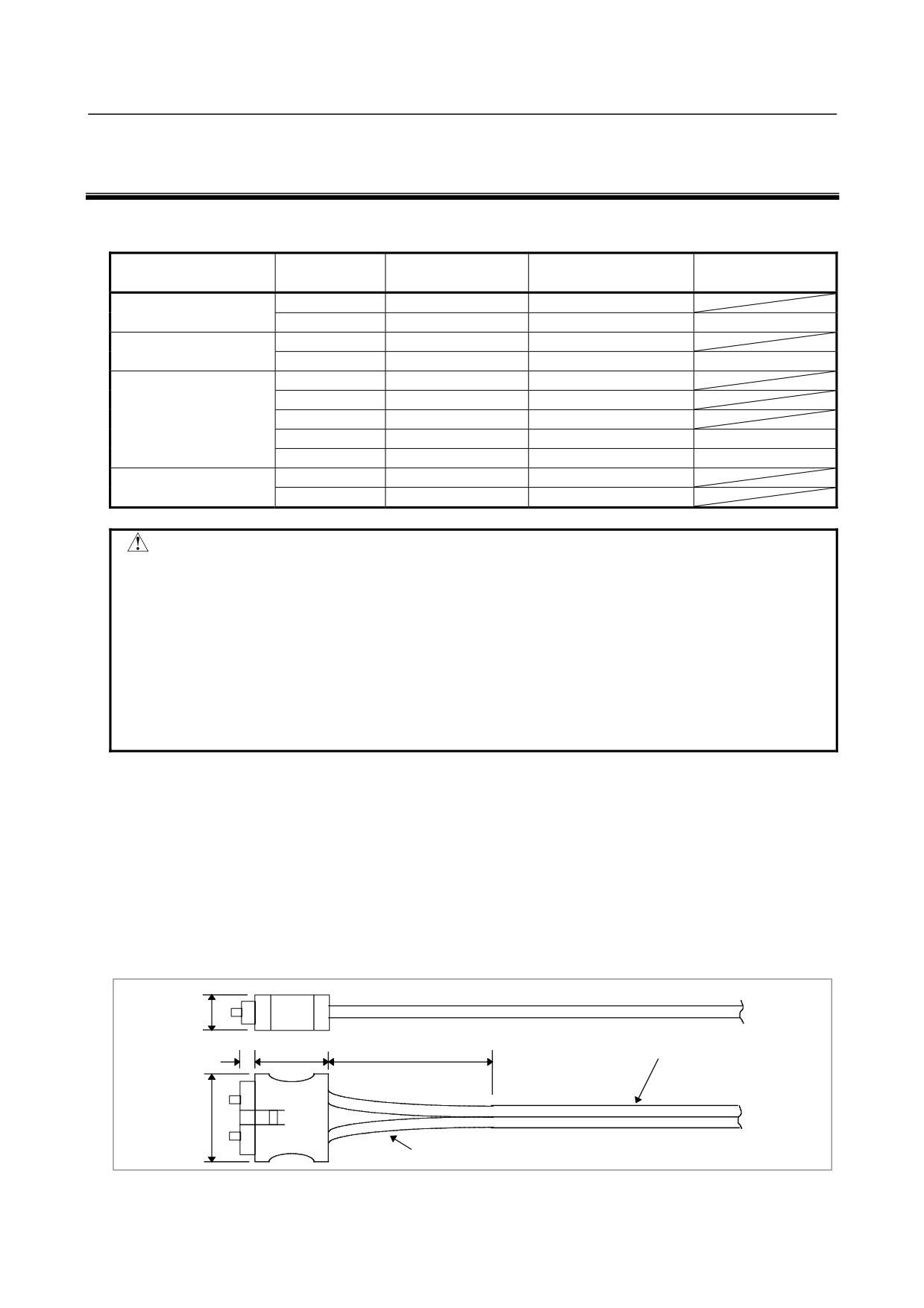
(1) Supported optical cables
<1> Internal cord type cable
A66L-6001-0023#LxRxxx
Cable length
0.15 to 10m
Code diameter
φ2.2mm × 2 cords
Tensile strength
Optical fiber cord
7 kg per cord
Between optical fiber cord and connector
2kg
Minimum bending radius of optical fiber cord
25mm
Operating temperature
-20 to 70 °C
Unit: mm
7
6.7
14 max.
100 typ.
Two cords are bound together.
21
Code
Fig. D (a) External dimensions of internal cord type cable
- 425 -
D.OPTICAL FIBER CABLE
APPENDIX
B-64303EN/03
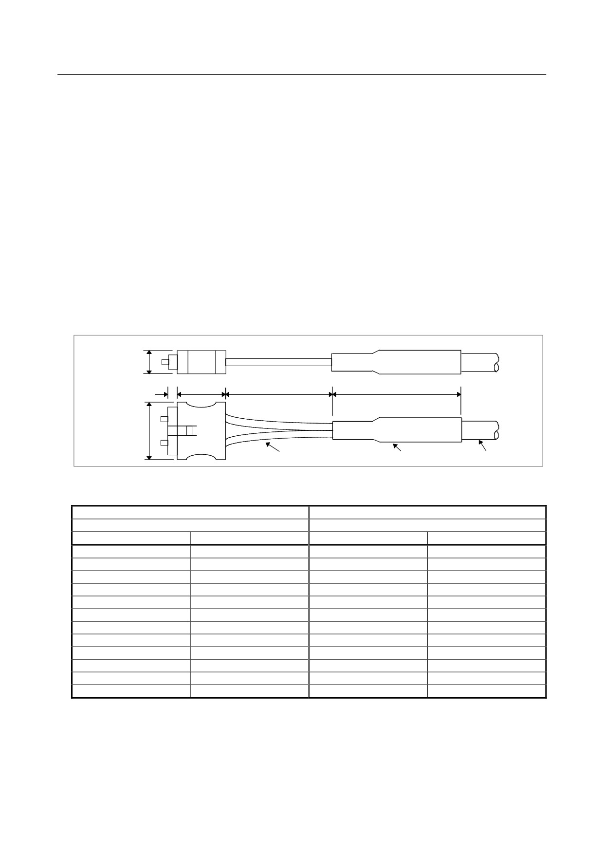
<1> External type cable
A66L-6001-0026#LxRxxx
..................................................................................A66L-6001-0029#LxRxxx
..................................................................................A66L-6001-0049#LxRxxx
Cable length
1 to 200m
Optical fiber cord diameter
φ2.2mm × 2 cords
Diameter of cable with reinforced cover
φ7.6mm (A66L-6001-0026, -0029)
..................................................................................φ8.2mm(A66L-6001-0049)
Tensile strength
Cable with reinforced cover
..............................75kg
Optical fiber cord
..............................7 kg per cord
Between optical fiber cord and connector
2kg
Minimum bending radius of optical fiber cord
25mm
Minimum bending radius of cable with reinforced cover
50mm
Bending resistance (cable with reinforced cover)
10 million bending cycles at room
temperature (when the bending radius
is 100 mm)
Flame resistance
Equivalent to UL VW-1
Operating temperature
-20 to 70 °C
Unit: mm
8.2
6.7
19 max.
150 typ.
35 typ.
21
Code
Bush
Reinforced cover
Fig. D (b) External dimensions of external cable
Table D (a) Standard cable length
Internal cord type cable
External cable
A66L-6001-0023#
A66L-6001-0026#
Specification
Length
Specification
Length
L150R0
0.15m
L1R003
1.0 m
L300R0
0.3 m
L2R003
2.0 m
L500R0
0.5 m
L3R003
3.0 m
L1R003
1.0 m
L5R003
5.0 m
L2R003
2.0 m
L7R003
7.0 m
L3R003
3.0 m
L10R03
10.0m
L5R003
5.0 m
L15R03
15.0m
L7R003
7.0 m
L20R03
20.0m
L10R03
10.0 m
L30R03
30.0m
L50R03
50.0m
L100R03
100m
L200R03
200m
(2) Cable selection
• Always use an external cable (A66L-6001-0026#~) when the cable is to be laid outside the power
magnetics cabinet or main unit cabinet, where it may be pulled, rubbed, or stepped on.
- 426 -
B-64303EN/03
APPENDIX
D.OPTICAL FIBER CABLE
• Use an external cable when part of the cabling is to be subject to movement. For example, when
connecting a movable portable operation pendant box to the power magnetics cabinet, the use of an
external cable is desirable because the cable is likely to be bent, pulled, or twisted repeatedly even
though frequent system operation is not expected. However, the force likely to be applied when the
cable is installed or moved for maintenance purposes does not need to be taken into consideration.
• Use an external cable in locations where sparks or flame are a danger. Although the internal cord
type cable (A66L-6001-0023#~) is covered by nonflammable resin, the cover, if exposed to frame
for a long time, may melt, allowing the fiber cable inside to burn.
• Use an external cable when the cable is expected to be pulled with considerable force during
installation (the force applied to the cable must be within the specified tensile strength limit at all
times). For example, even though installing a cable in a cable duct can be regarded as internal
cabling, a cable of the appropriate type must be selected according to the tensile force to be applied
to the cable during installation.
• Both the internal cord type and external cables have the same oil and heat resistance properties.
(3) Procuring the cable
All the optical fiber cables mentioned above are special cable products with optical connectors, which are
designed, produced, and tested to ensure the required system performance and reliability. It is
technically impossible for users to produce these cables or process (cut and reconnect) them after
purchase. Users are requested to purchase cables of the necessary length from an appropriate supplier.
Cables are available from either FANUC or any of the FANUC-approved manufacturers listed in Table
D(d).
(Purchase A66L-6001-0029#~ and A66L-6001-0049#~ from FANUC, however.)
Table D(d) FANUC-approved cable manufacturers and cable model numbers (retail)
<1> Internal cord type cable : A66L-6001-0023#LxRxxx
Manufacturer
Model number
Remark
Tyco Electronics AMP
*-353373-*
Japan Aviation Electronics Industry
PF-2HB209-**M-F-1
** indicates the cable length (m).
Hirose Electric Co., Ltd.
H07-P22-F2VCFA-**
** indicates the cable length (m).
<2> External Cable : A66L-6001-0026#LxRxxx
Manufacturer
Model number
Remark
Tyco Electronics AMP
*-353199-*
Japan Aviation Electronics Industry)
CF-2HB208-**M-F-1
** indicates the cable length (m).
Hirose Electric Co., Ltd.
H07-P22-F2NCFA-**
** indicates the cable length (m).
Oki Electric Cable Co., Ltd.
OPC201HPXF-**MB
** indicates the cable length (m).
(4) Handling precautions
<1> Protection during storage
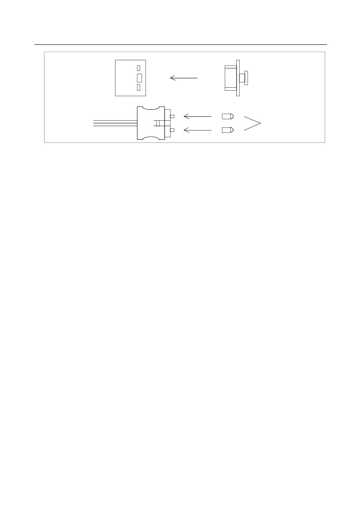
When the electrical/optical conversion module mounted on the printed circuit board and the optical
fiber cable are not in use, their mating surfaces must be protected with the lid and caps with which
they are supplied. If left uncovered, the mating surfaces are likely to become dirty, possibly
resulting in a poor cable connection.
- 427 -
D.OPTICAL FIBER CABLE
APPENDIX
B-64303EN/03
Electrical/optical conversion module
Lid
Optical fiber cable
Optical fiber cable caps
Fig. D (c) Protection of electrical/optical conversion module and optical fiber cable (when not in use)
<2> Optical fiber cable
•
Make sure that the bending radius and tensile strength of the cable are always within their
ranges described in the specifications (see the first item), regardless of whether the cable is
stored or routed and whether operation is in progress or not.
•
Although the reinforcing cover of the external cable has sufficient mechanical strength, be
careful not to drop heavy objects on the cable.
•
Grasp the optical connector firmly when connecting or disconnecting the cable. Do not pull
on the optical fiber cord itself.
(The maximum tensile strength between the fiber cord and
connector is 2 kg. Applying greater force to the cord is likely to cause the connector to come
off, making the cable unusable.)
•
Once connected, the optical connector is automatically locked by the lock levers on its top.
To remove the connector, release the lock levers and pull the connector.
•
Although optical connectors cannot be connected in other than the correct orientation, always
take note of the connector's orientation before making the connection.
•
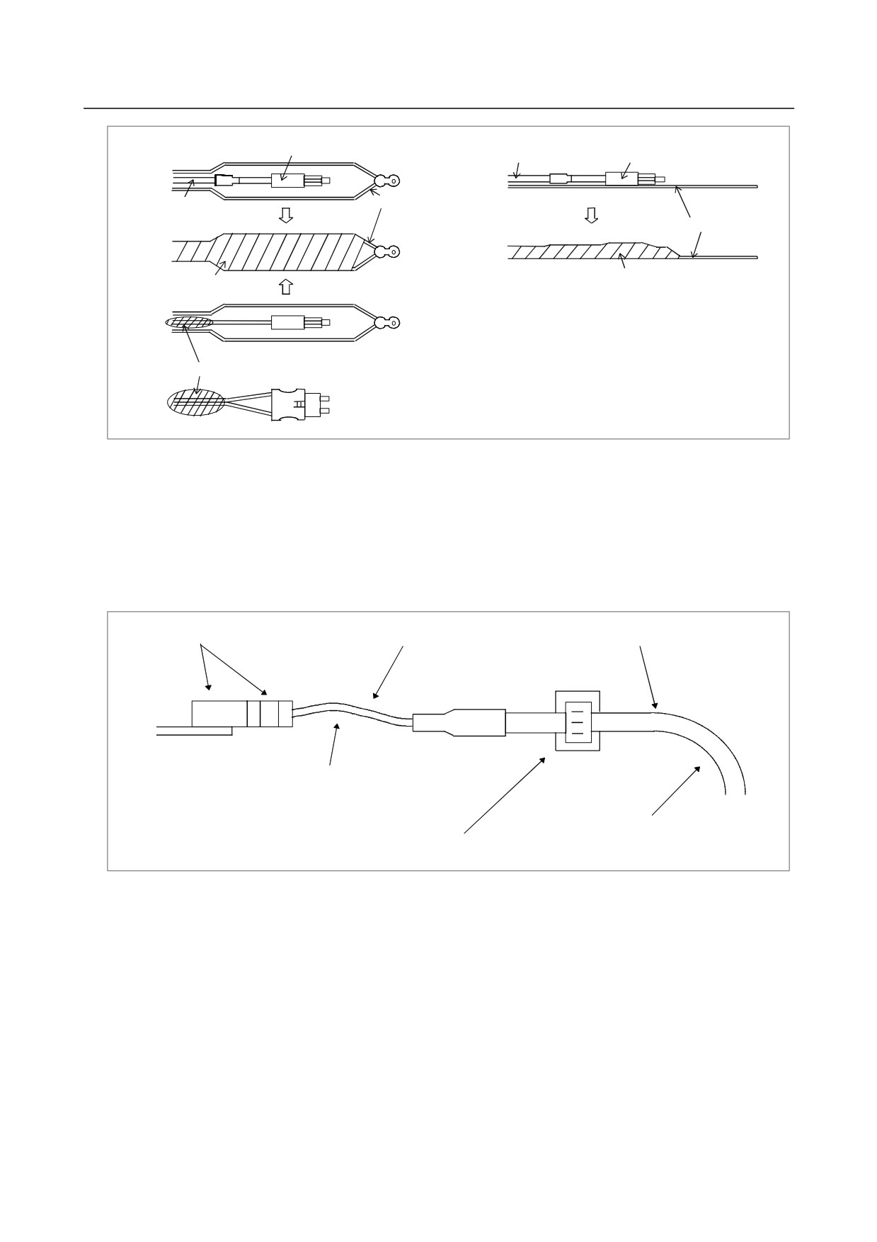
Before installing an external cable, fix either a wire with a hook or a tension member to the
reinforcing cover of the optical connector and pull the wire or tension member, as shown in Fig.
D(d). This is done to prevent a tensile force from being applied between the fiber cord and
connector. If no tensile force is applied between the fiber cord and connector when installing
the cable, you can hold the reinforcing cover of the connector directly and pull it. In the case
of an internal cord, which does not have a reinforcing cover, apply the same protective
measures, as instructed in Fig. D(d), for that portion of the cable where the two cords are bound
together, in order to prevent a tensile force from being applied between the fiber cord and
connector. In the same way as for an external cable, if no tensile force is applied between the
fiber cord and connector during installation, you can hold the shielded part of the cable directly
and pull it. Because the combined tensile strength of the two cords is only 14 kg, however,
avoid applying too great a force to the cable during installation, regardless of whether you have
taken the protective measures.
- 428 -
B-64303EN/03
APPENDIX
D.OPTICAL FIBER CABLE
Optical connector
Reinforcing cover Optical connector
Wire with a hook
Reinforcing cover
Tension member
Tape
Tape
2 cords combined
Fig. D (d) Prior to installing a cable
•
Take care to keep both parts of the optical connector (cable side and PCB side) clean. If they
become dirty, wipe them with tissue paper or absorbent cotton to remove dirt. The tissue
paper or absorbent cotton may be moistened with ethyl alcohol. Do not use any organic
solvent other than ethyl alcohol.
•
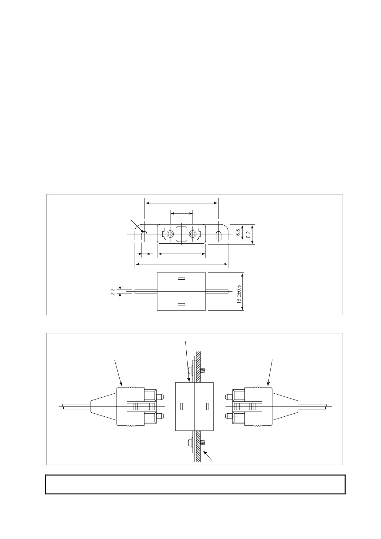
Fix the reinforcing cover of the external cable or the cord binding portion of the internal cord
type cable by using a cable clamp, as shown in Fig. D(e), to prevent the weight of the optical
fiber cable from being applied directly to the connecting part of the optical connector.
Reinforcing cover of external cable or cord
Optical connector
Optical fiber cord
binding portion of internal cord type cable
Bending radius of 25 mm or more
(Make the bending radius as large
as possible.)
Bending radius of 50 mm or more (for reinforcing cover)
Cable clamp
Bending radius of 25 mm or more (for cord binding portion)
(Make the bending radius as large as possible.)
Fig. D(e) Fixing the cable with a clamp
• Any superfluous portion of the cable may be wound into a loops. Should this prove necessary,
make sure the diameter of each loop is at least 150 mm (for an external cable) or at least 100
mm (for an internal cord type cable). Winding the cable into smaller loops may produce sharp
curves that exceed the specified bending radius limit without the user being aware. Such
bending can result in a greater transmission loss, ultimately leading to a communication failure.
•
When using a nylon band (cable tie) as a cable clamp, follow the instructions given below.
Also, take care not to apply a bending force to one particular part of the cable when fixing it
with a clamp. Failing to clamp the cable correctly may cut or damage it.
- 429 -
D.OPTICAL FIBER CABLE
APPENDIX
B-64303EN/03
(External cable)
Do not clamp the uncovered portion of the cable with a nylon band. When clamping the
cable by the reinforcing cover, the clamping force is not an important factor to consider.
However, ensure that the clamping force is as small as possible to ensure that the
reinforcing cover is not deformed by the clamping. If possible, the clamping force
should be 5 kg or less.
(Internal cord type cable)
Lightly clamp the optical cable with a nylon band so that the cable shield is not deformed.
If possible, the clamping force should be 1 or 2 kg (make sure that no force is applied to
the cable). Due care is required when clamping the internal cord type cable because its
cable shield is weaker than the reinforcing cover of the external cable.
(5) Optical fiber cable relay of FANUC I/O Link
When used for the FANUC I/O Link application, optical fiber cables can be connected by using an optical
fiber adapter, as follows.
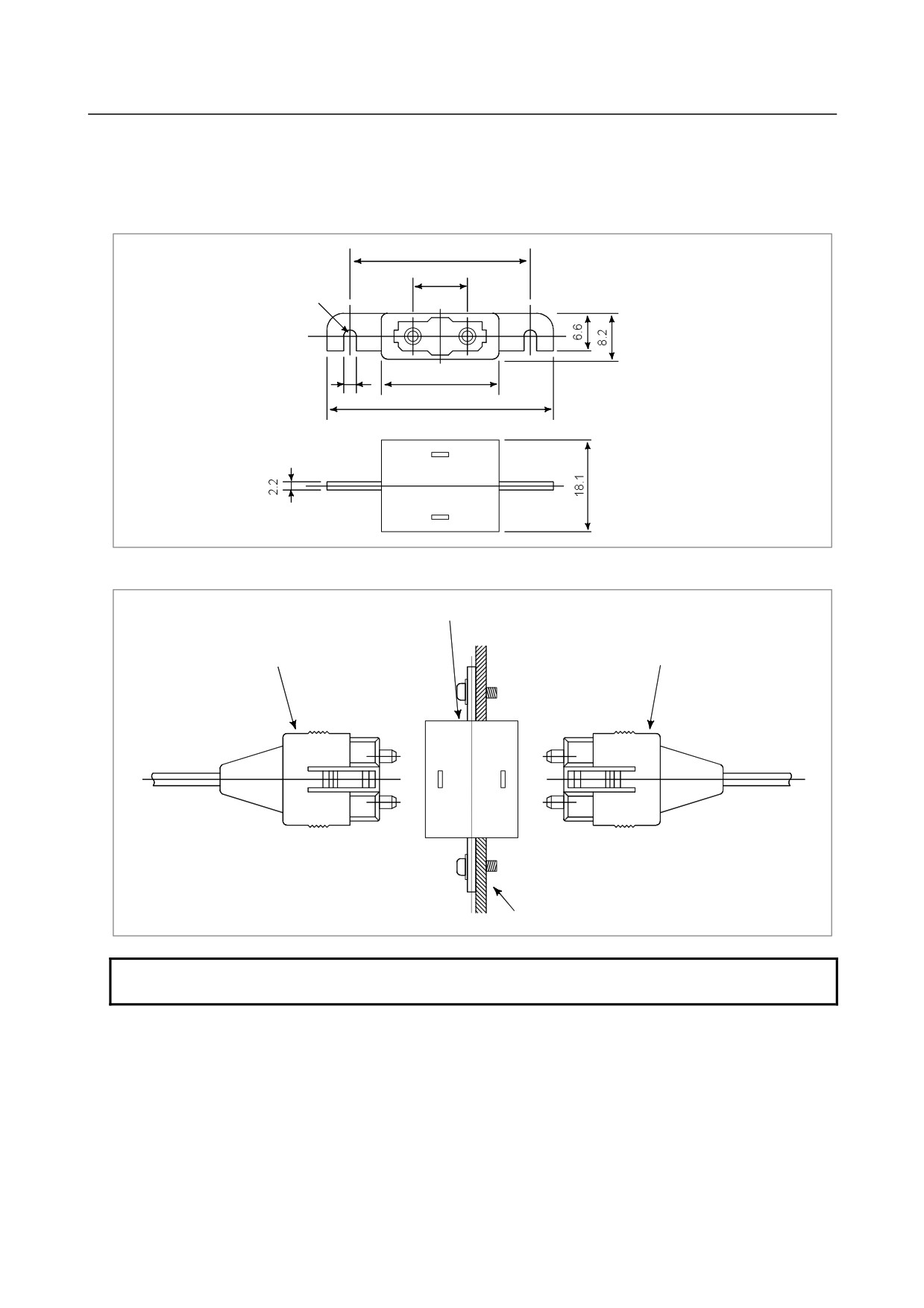
(a) External view of an optical fiber adapter
32±0.3
10.16
R1.6
21±0.5
3.2
42±0.5
(b) Example of the use of an optical fiber adapter
Optical fiber adapter (A63L-0020-0002)
Optical fiber cable
Optical fiber cable
Mounting board
NOTE
Up to one relay points are permitte.
- 430 -
B-64303EN/03
APPENDIX
D.OPTICAL FIBER CABLE
(6) Optical fiber cable relay of FANUC high-speed serial bus
With the FANUC high-speed serial bus, special low-loss optical cables can be connected by using a
special low-loss optical relay adapter as an optical fiber relay adapter.
(a) External view of the low-loss optical relay adapter
32±0.5
10.16
R1.6
21±0.3
3.2
42±1.0
(b) Example of use of the optical fiber relay adapter
Low-loss optical relay adapter (A63L-0020-0004)
Low-loss optical fiber cable
Low-loss optical fiber cable
Mounting board
NOTE
Only one relay point is permitted.
(7) Precautions for connection with low-loss optical junction adapter
• Features and attention in use of low-loss optical junction adapter (A63L-0020-0004)
When optical connectors for a conventional optical junction adapter (A63L-0020-0002) are jointed,
the facing ferrules (Note 1) are located about 60 um from each other. This is because the optical
fiber of conventional PCF (plastic clad silica fiber) cables (A66L-6001-0026) may protrude from the
tip of the ferrules (by up to about several um), resulting in the fiber protrusion being damaged when
the ferrules are butted against each other.
- 431 -
D.OPTICAL FIBER CABLE
APPENDIX
B-64303EN/03
In the low-loss optical junction adapter, the ferrules are butted against each other, thus greatly
reducing the reduction in repeater loss. Therefore, the two optical cables used with the low-loss
optical junction adapters must be dedicated to the adapters.
If a conventional PCF (plastic clad silica fiber) cable (A66L-6001-0026) is used as even one of the
two optical fiber cables for joining the low-loss optical junction adapter, both cables may be
damaged, resulting in deteriorated characteristics.
NOTE
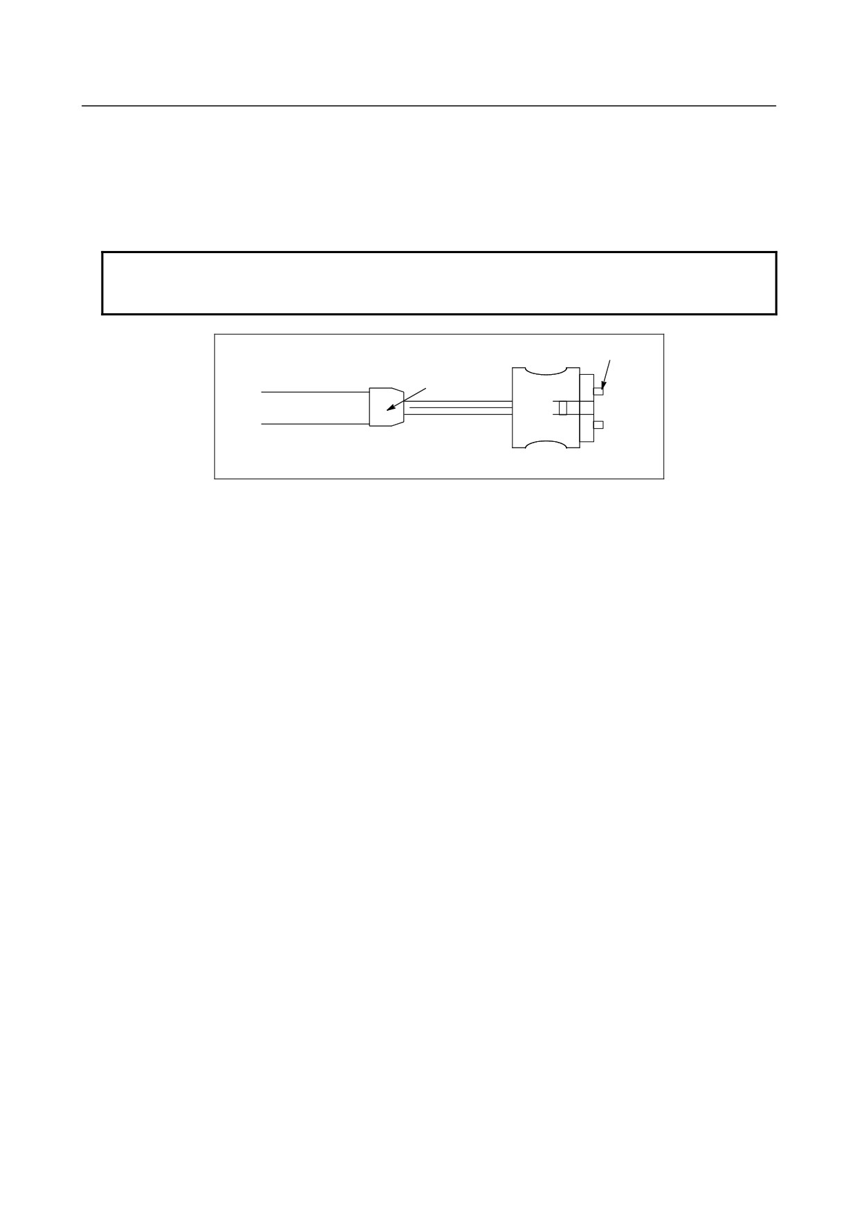
Ferrule: Movable metal at the tip of an optical connector; the fiber is bonded to
the ferrule.
Ferrule
Protective cover
Optical cable
Optical connector
• Features of low-loss optical cable (A66L-6001-0029#~)
A low-loss optical cable is selected from conventional PCF optical cables (A66L-6601-0026). The
selected cable offers low loss, and its connector section is given special treatment; the fiber ends are
provided with a depression so that the ferrules can be butted against each other
• Features of high-speed, low-loss optical cable (A66L-6001-0049#~)
The type of optical fiber used for a high-speed, low-loss optical cable has optical properties different
from that of conventional PCF optical cables (A66L-6001-0026 and A66L-6001-0029) to support
high-speed, long-distance communication. They are different in how the light propagates within
the fiber. Relaying different types of optical fibers may increase repeater loss, resulting in an
optical communication failure.
• When using a low-loss optical relay adapter, be sure to use the same type of optical cable
(high-speed, low-loss optical cables or low-loss optical cables).
• Colors of low-loss optical relay adapter and low-loss optical cable (distinguishing them from
conventional products)
While the color of the body of the conventional optical relay adapter is black, that of the low-loss
optical relay adapter is blue. While the color of the protection cover (Refer to above figure) of the
conventional PCF optical cable is black, that of the low-loss optical cable is blue.
(8) Installing the optical fiber junction adapter
The optical fiber junction adapter should be installed within a cabinet, as a rule. If it is impossible to
avoid installing it within a cabinet, protect the adapter and the optical cable portions (such as connectors
and cords) not covered with reinforcement coating from the outside air by, for example, covering them
with packing.
(9) Environmental resistance of the optical fiber junction adapter
• The optical fiber junction adapter is not waterproof. Even when optical cables are attached to both
ends of the adapter, there are very small gaps in the linked portions, so water resistance can not be
expected.
- 432 -
B-64303EN/03
APPENDIX
D.OPTICAL FIBER CABLE
• When optical cables are attached to both ends of the junction adapter installed in a normal
environment (such as within a cabinet), it is unlikely that dust will penetrate between the adapter
and optical fiber to the degree that it may hamper normal optical linkage. If one or both ends of the
adapter are left open, dust and dirt may accumulate even when the adapter is in a normal
environment (such as within a cabinet). The dust and dirt on the adapter ends is likely to hamper
normal optical linkage when the optical cables are attached. In such a case, clean the junction
adapter and the optical connector using the optical fiber junction adapter cleaning method described
below.
• Do not allow cutting fluid to splash over the adapter or those optical cable portions (such as
connectors and cords) that are not covered with reinforcement coating. If the inside of the adapter
and fiber end surfaces are contaminated with cutting fluid, a malfunction may occur.
(10) Cleaning
If the optical fiber junction adapter, optical-to-electrical conversion module, or optical cable are soiled,
clean them according to the following procedures.
• Cleaning the optical fiber junction adapter and optical-to-electrical conversion module
First, clean the entire housing by wiping it with a cloth moistened with, or by washing it in, ethyl
alcohol. Similarly, wash the two sleeves in the adapter or wipe them with a cotton swab or the like.
• Cleaning optical cables
For the optical cables, it is important to clean the connectors at their ends. Any soiling on the
optical fiber end surfaces will hamper optical transmission, resulting in a malfunction. Wipe the
optical fiber end surfaces (that is, the ferrule end surfaces) thoroughly with a soft, clean cloth (like
gauze) moistened with ethyl alcohol, in the same way as described above. The use of cotton swabs
may prove convenient. The fiber end surfaces of low-loss optical cables are lower than the ferrules.
To remove any soiling from the fiber end surfaces completely, push the cotton swab or gauze into
the depressions all the way through while rotating the ferrule.
If the ferrules and optical connectors are contaminated with oily substances, and they may extend
over a cleaned fiber end surface when it is attached to the optical-to-electrical conversion module, it
is a good idea to wash them before wiping the optical fiber end surfaces, using the procedure stated
above.
- 433 -

E.LIQUID CRYSTAL DISPLAY (LCD) APPENDIX
B-64303EN/03
E LIQUID CRYSTAL DISPLAY (LCD)
LCD with a touch panel
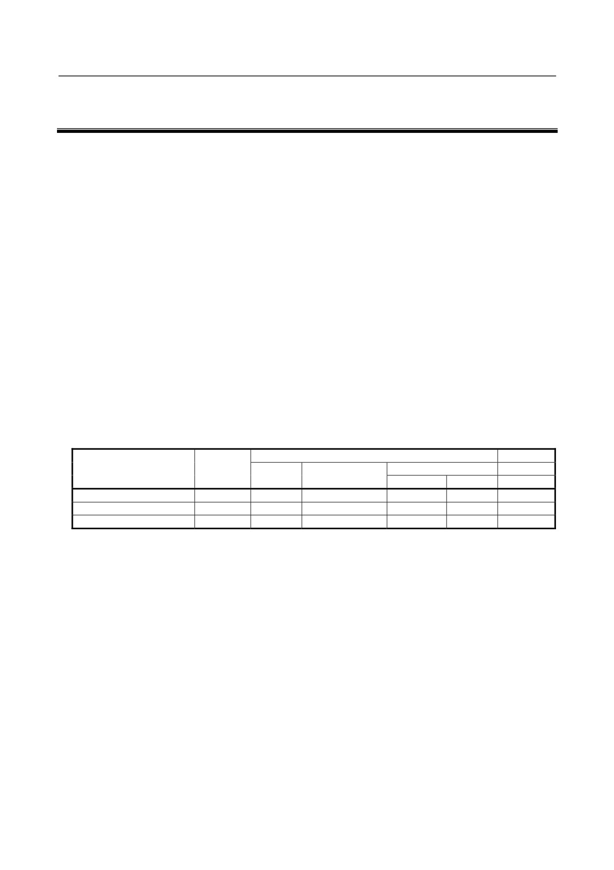
The touch panel is operated by directly touching the LCD screen. For this operation, be sure to use a
FANUC-supplied pen (A02B-0236-K111) dedicated to the touch panel. If a sharp-pointed pen is used,
for example, to touch the LCD screen, the LCD surface may be flawed or damaged. Moreover, do not
touch the LCD screen directly with a finger. Otherwise, the operability of the LCD may deteriorate, and
the LCD screen may get dirty.
Protection sheet for the touch panel
A protection sheet is attached the face of an LCD with a touch panel to protect the thin film of the touch
panel and LCD. If the protection sheet is damaged, it can be replaced. For the replacement method,
refer to the maintenance manual.
(The protection sheet is a consumable part.)
- 434 -
B-64303EN/03
APPENDIX
F.MEMORY CARD INTERFACE
F MEMORY CARD INTERFACE
Overview
The LCD-mounted type can input and output data within the CNC using the memory card interface on the
left side of the LCD, and edit or execute a machine program in the CF card inserted into the memory card
interface.
The stand-alone type can input and output data within the CNC using the memory card interface of the
control unit.
(The stand-alone type cannot edit or execute a machine program in the CF card inserted
into the memory card interface.) For an explanation of remote diagnosis using a modem card, see the
related document.
CF card
Since a CF card includes flash memory, if read operation is repeated over a long period of time, an data
error occurs in some rare cases due to internal data corruption. Commercial CF cards generally do not
sufficiently address such a data error. In addition, read operation may take much time depending on the
state of internal memory; if there is a delay in transferring data to the CNC during DNC operation, the
finished quality of the machined surface may be affected.
The CF cards recommended below have a superior capability of correcting data automatically and are
designed so as not to read incorrect data even if a data error occurs. If these cards are used under the
machining conditions defined below, the finished quality of the machined surface is not affected.
1.
Recommended memory cards
The recommended memory cards and their usages are shown in the table below.
Table 1-1. Recommended memory cards
Usage
Remarks
Order specification
Capacity
DNC operation by
Data server
Data I/O
memory card
100 Base
10 Base
A02B-0281-K601
128 MB
○
○
○
○
CF
A02B-0213-K211
256 MB
○
○
○
○
CF
A02B-0213-K212
1 GB
○
○
○
○
CF
○: Normal operation confirmed.
×: Normal operation not guaranteed.
CF: Compact flash
*: Compact flash adapter
- The compact flash card adapter (A02B-0303-K150) was used to check the data I/O and
automatic operation on the PCMCIA port.
- The adapter (SDCF-31-03) manufactured by SanDisk was used to check the operation of the
data server.
2.
Others
•
The format of the flash ATA card is the quick format.
An unformatted flash ATA card needs to be formatted by your PC using FAT16. Other
formats are not supported.
Using the compact flash adapter (LCD-mounted type only)
1.
Attachment
•
Attach the compact flash card to the compact flash card adapter (A02B-0303-K150, called the
CF adapter later).
•
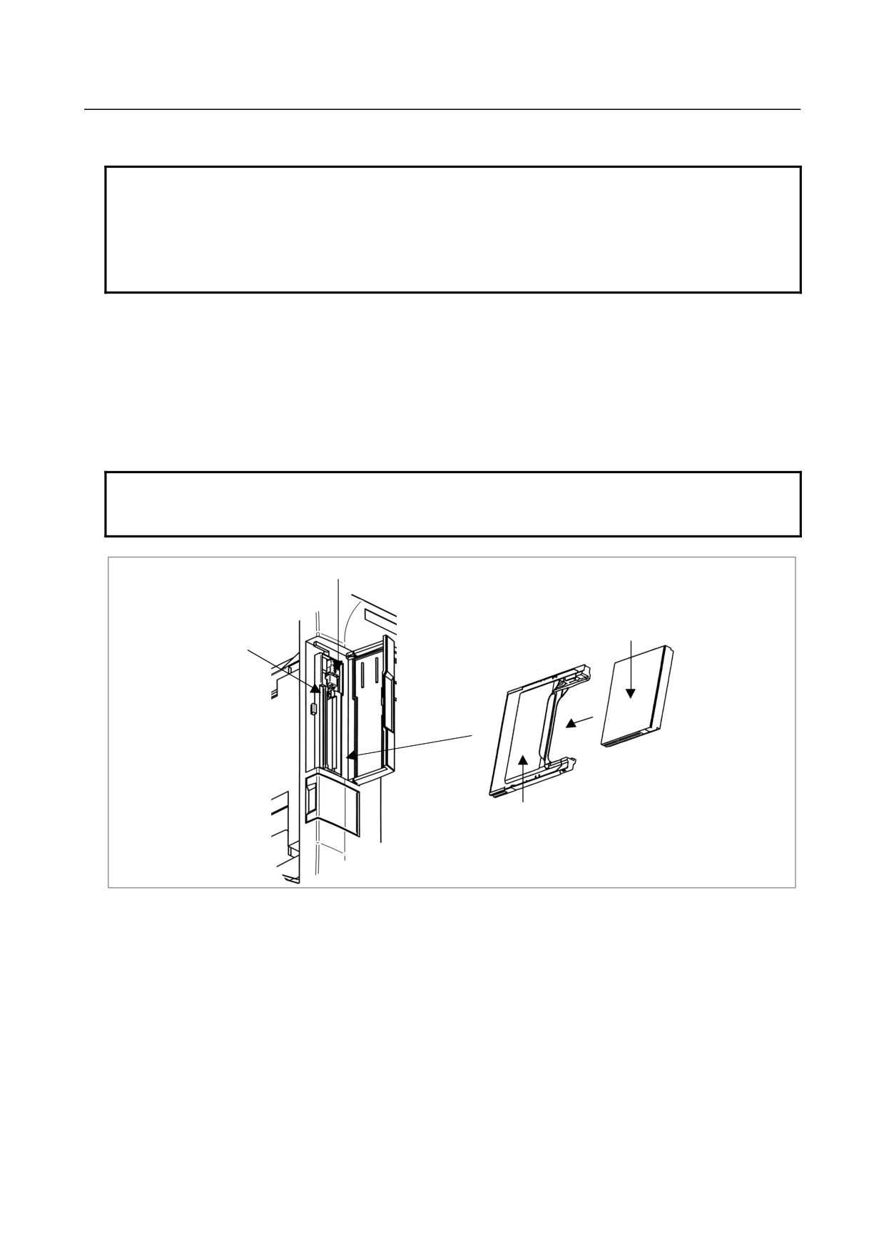
Make sure lock lever A is in the upper position and then insert the CF adapter above into the
memory card interface.
•
Push lock lever A downward.
- 435 -
F.MEMORY CARD INTERFACE
APPENDIX
B-64303EN/03
•
Close the cover of the memory card interface.
NOTE
1 To perform continuous operation with the CF adapter attached, be sure to push
lock lever A downward and then close the cover of the memory card interface.
2 The lock function is enabled only when the CF adapter (A02B-0303-K150) is
used.
3 The CF adapter must be inserted with label surface facing toward the screen.
2.
Removal
•
Open the cover of the memory card interface.
•
Push lock lever A upward.
•
Push eject button B once to project the button.
•
Push eject button B again to eject the CF adapter.
•
Remove the CF card with your fingers.
•
Close the cover of the memory card interface.
NOTE
1 When lock lever A is in the lower position (in the locked state), eject button B
cannot be pushed.
Lock lever A
Compact flash card
Eject button B
Compact flash card adapter
Notes on DNC operation and memory operation using a memory card
attached to the memory card interface
Since a CF card includes flash memory, if read operation is repeated over a long period of time, an data
error occurs in some rare cases due to internal data corruption.
This CF card has a capability of correcting data automatically and is designed so as not to read incorrect
data even if a data error occurs, but it temporarily takes much time.
The delay in read operation affects the performance (speed) of DNC operation and memory operation and
the finished quality, so this must be considered while the use conditions are determined. Set the
processing time for one block to 4 ms or more.
When high performance is required or an expensive workpiece is machined, use the data server (DNC
operation). In DNC operation on the data server, the above delay in read operation does not affect the
performance or finished quality.
Use ISO code as format of NC program.
- 436 -