FANUC Series 0i-MODEL D, Series 0i Mate-MODEL D. CONNECTION MANUAL (HARDWARE) - page 13
B-64303EN/03
10.STOP AND EMERGENCY STOP
10.3 STOPPING THE SPINDLE MOTOR
While the spindle motor is running, shutting off the motor power allows the spindle motor to coast at a
speed maintained before shut-off and eventually stop (after a while). However, there may be cases
where the spindle motor should be stopped as soon as possible for safety reasons. In such cases, a stop
of the spindle motor depends on a Ladder program prepared by the machine tool builder. If the CNC
detects an abnormal condition, it outputs an alarm to the PMC. The Ladder program should specify
processing to be performed when an alarm is output: allowing the spindle to continue running,
decelerating the spindle to a stop, or causing the spindle to coast, for example.
To decelerate the spindle to a stop, a spindle emergency stop signal (such as *ESPA (G71.1) or *ESPB
(G75.1)) can be input in the PMC. Inputting this signal cause the spindle to be decelerated to a stop.
(A Ladder program must be created so that this signal is input if an alarm occurs.) The same effect can
be achieved by using the PSM emergency stop input (connector CX4). When an emergency stop signal
is connected to the
*EMGPSM emergency stop input (connector CX4), therefore, the spindle is
decelerated to a stop if the CNC enters the emergency stop state.
CAUTION
1 If the CNC enters the system alarm state, the Ladder program does not run. In
this case, the spindle amplifier can be decelerated to a stop. Make proper
parameter settings because such a stop depends on the settings.
2 If the spindle motor cannot be controlled due to an alarm in the spindle amplifier
itself or for some other reason, the motor power is shut off by the IGBT
immediately. After the servo motor has stopped, an MCC control signal is
output.
10.4 STOPPING THE SERVO MOTOR
Shutting off the motor power brings the servo motor to a dynamic brake stop. A dynamic brake stop is
braking performed by separating the synchronous rotator from the driving power, and consuming
generated electric energies with the coil as well as the built-in resistor of the servo amplifier. With this
function, shutting off the motor power does not allow the servo motor to coast like the
spindle motor.
Servo motor stop mode depends on the type of a CNC alarm.
Example)
1.
PS alarm caused by an NC program error or the like
The motor power is not shut off.
2.
CNC fan stop
A single-block stop is made. The motor power is not shut off.
3.
Emergency stop state
A dynamic stop is made as a rule. By setting relevant parameters, however, it is also possible to
decelerate the servo motor to a stop, and then to shut off the servo motor power.
4.
System alarm
A dynamic brake stop is made.
If the servo motor cannot be controlled, a dynamic brake stop is unconditionally made.
- 347 -
10.STOP AND EMERGENCY STOP
B-64303EN/03
10.5 EMERGENCY STOP SIGNAL
CAUTION
Using the emergency stop signal effectively enables the design of safe machine
tools. See "Cautions for configuring an emergency stop circuit in compliance
with safety standards."
The emergency stop signal is provided to bring a machine tool to an emergency
stop. It is input to the CNC controller and αi series power supply module. The
power supply module outputs a motor power MCC control signal, which can be
used to switch the power applied to the power supply module on and off. An
emergency stop signal is usually generated by closing the B contact of a
pushbutton switch.
When the emergency stop signal (*ESP) contact is closed, the CNC controller
enters the emergency stop released state, such that the servo and spindle
motors can be controlled and operated.
When the emergency stop signal (*ESP) contact opens, the CNC controller is
reset and enters the emergency stop state, and the servo and spindle motors
stop.
Inputting an emergency stop signal causes the servo motor power to be shut off
through the IGBT, bringing the servo motor to a dynamic brake stop. Even in
this case, however, a servo motor attached to a vertical axis can move under the
force of gravity. To overcome this problem, use a servo motor with a brake.
By using relevant parameters, it is also possible to decelerate the servo motor to
a stop, and then to shut off the servo motor power.
While the spindle motor is running, shutting off the motor power to the spindle
amplifier allows the spindle motor to continue running under its own inertia,
which may be quite dangerous. With an αi series amplifier, when the
emergency stop signal (*ESP) contact opens, it is possible to confirm that the
spindle motor is decelerated to a stop, and then to shut off the spindle motor
power through the IGBT.
When the motor power to both servo and spindle amplifiers is shut off through
the IGBT, the power supply module outputs a motor power MCC control signal,
which can be used to directly shut off the power with an external line contactor.
The CNC controller is designed to detect overtravel by using a software limit
function. Normally, no hardware limit switch is required to detect overtravel. If
the machine goes beyond a software limit because of a servo feedback failure,
however, it is necessary to provide a stroke end limit switch, which should be
connected so that the emergency stop signal can be used to stop the machine.
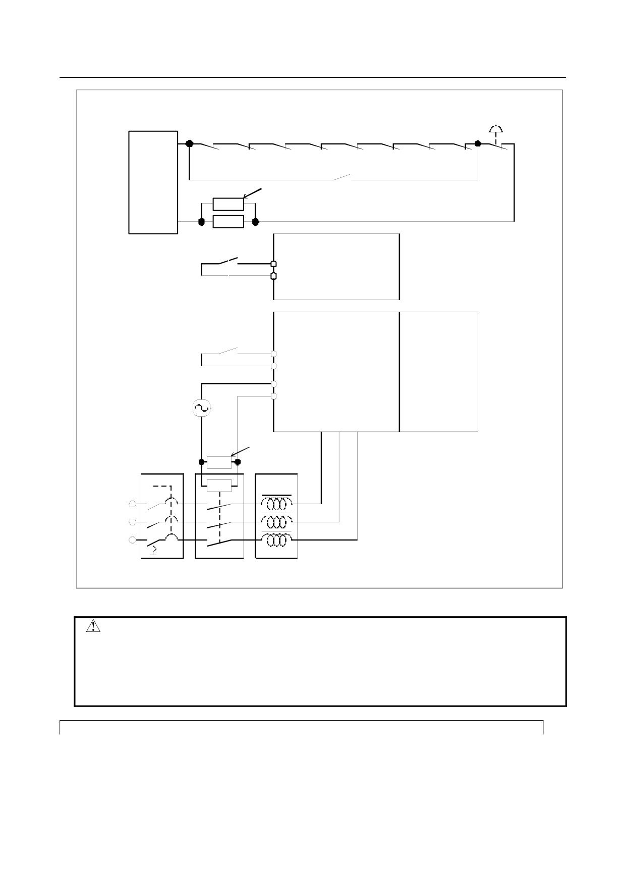
Fig. 10.5 shows an example showing how to make connections for the
emergency stop signal with this CNC controller and αi series servo amplifier.
- 348 -
B-64303EN/03
10.STOP AND EMERGENCY STOP
St roke end limit switch
Emergency
stop butt on
+‚w
-w
+x
-x
+y
-y
+4
-4
Relay
power
Release switch
Spark killer
S K
E MG
Relay
I /O unit (module) connected t o
emg1
t he CNC
+24
* ESP
α i series servo amplif ier (PSM)
SVM
SPM
emg2
+24
* ESP
MCCOFF3
MCCOFF4
Ext ernal
power
L1
L2 L3
source
Spark killer
SK
3φ
coil
200VAC
L1
L2
L3
Circuit
MCC AC reactor
breaker 1
Fig. 10.5
WARNING
To use a spindle motor and amplifier produced by a manufacturer other than
FANUC, refer to the corresponding documentation as well as this manual.
Design the emergency stop sequence such that, if the emergency stop signal
contact opens while the spindle motor is rotating, the spindle motor is
decelerated until it stops.
Cautions for configuring an emergency stop circuit in compliance with safety standards
To configure an emergency stop circuit in compliance with JIS safety standards(*), observe the following
cautions. Compliance with these JIS safety standards is a prerequisite for complying with the EC Machine
Instructions.
The method for shutting off the motor power section in the amplifier is based on an IGBT (transistor)
rather than an electromechanical scheme.
- 349 -

10.STOP AND EMERGENCY STOP
B-64303EN/03
When configuring an emergency stop circuit, therefore, install a line contactor on the power input line for
motor power in the power supply module in order to ensure electromechanical shut-off, and apply voltage
to the control coil of the contactor via the contactor control output of the power supply module.
A failure in the amplifier may disable the output relay of the power supply module from going off, thus
preventing the line contactor from shutting off the power, even when the emergency stop command input
(*ESP) of the amplifier becomes low.
To secure motor power shut-off, design the emergency stop circuit in a redundancy configuration. To be
specific, the emergency stop circuit must have a direct line contactor shut-off route based on an
emergency stop switch that is independent of the shut-off function of the amplifier.
If a spindle amplifier module is used, shutting off the motor power line during spindle rotation disables
the spindle from stopping quickly because the power regenerative function does not work, allowing the
spindle to coast. So, provide the redundancy circuit mentioned above with a delay function based on an
off-delay timer that allows a usual stop time.
Refer to the following material for detailed descriptions about cautions related to safety circuits.
A-71429-S13J:
About Requirements for Safety Circuits and Configuration Samples
To get a copy of this material, contact your FANUC sales representative.
- 350 -

B-64303EN/03
11.CONNECTION TO OTHER NETWORKS
11 CONNECTION TO OTHER NETWORKS
It is possible to make connection to other networks. For an explanation of how to make the connection,
refer to the manuals listed below:
Manual title
Manual code
Fast Ethernet / Fast Data Server OPERATOR’S MANUAL
B-64414EN
PROFIBUS-DP Board CONNECTION MANUAL
B-64403EN
DeviceNet Board CONNECTION MANUAL
B-64443EN
FL-net Board CONNECTION MANUAL
B-64453EN
- 351 -

12.CONNECTION OF THE STAND-ALONE TYPE
B-64303EN/03
12 CONNECTION OF THE STAND-ALONE
TYPE
12.1 OVERVIEW
The Series 0i-D supports the stand-alone type in which the display unit is separated from the control unit.
(The Series 0i Mate-D does not have the stand-alone type.)
The stand-alone type Series 0i-D uses the FANUC PANEL i or an IBM PC compatible PC as a display
device.
This chapter mainly provides descriptions specific to connection of the stand-alone type. For
descriptions common to the stand-alone type and LCD-mounted type, which are not given in this chapter,
see other chapters. For connection of the FANUC PANEL i, refer to the FANUC PANEL i Connection
and Maintenance Manual (B-64223EN).
The type in which the display unit is integrated with the control unit is called the LCD-mounted type and
the type in which the display unit is separated from the control unit is called the stand-alone type below.
- 352 -
B-64303EN/03
12.CONNECTION OF THE STAND-ALONE TYPE
12.2 CONTROL UNIT CONFIGURATION AND COMPONENT
NAMES
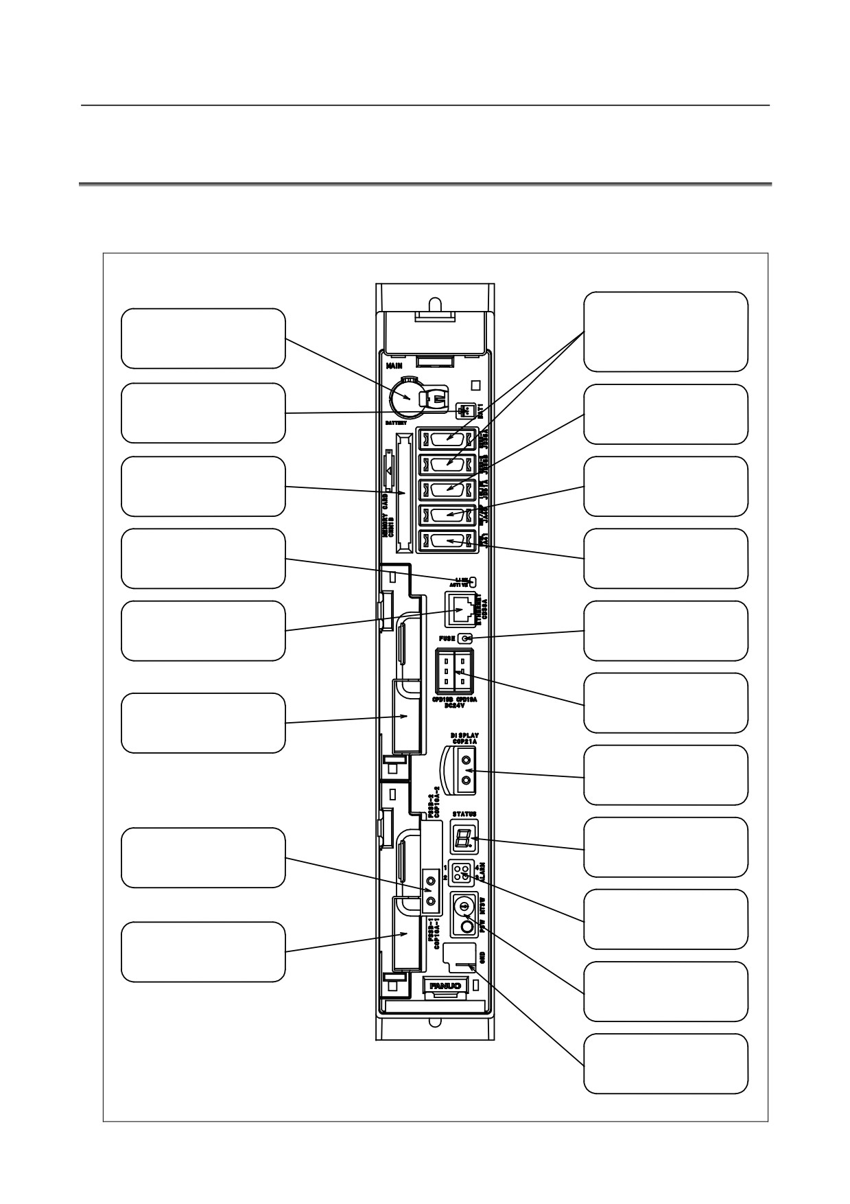
The configuration and component names of control units are shown in the figures given below. The
numbers in parentheses () in the figures are keyed to the item numbers of the descriptions in this manual.
The numbers in brackets [] in the figures are connector numbers.
I/O device interface
connector
[JD36A] (upper)
Battery
[JD36B] (lower)
(5.2)
I/O link connector
Battery
[JD51A] (9)
connector
Analog spindle or
Memory card
high-speed skip connector
interface
[JA40] (5.3, 6.2)
Serial spindle or position
LED display section
coder connector
for Ethernet
[JA41] (6.1, 6.3)
Fuse burn-out
Ethernet connector
detection LED
[JD38A] (5.4)
24VDC power supply
connector
[CPD19A] (right)
Optional slot 1
[CPD19B] (left)
Display unit
connector
[COP21A]
LED section for
Servo unit connector
status display and
(FSSB)
maintenance
[COP10A-1] (7)
LED section for
alarm display
Optional slot 2
Rotary witch for
maintenance (upper)
Bush witch for
maintenance (lower)
GND connection
terminal
- 353 -
12.CONNECTION OF THE STAND-ALONE TYPE
B-64303EN/03
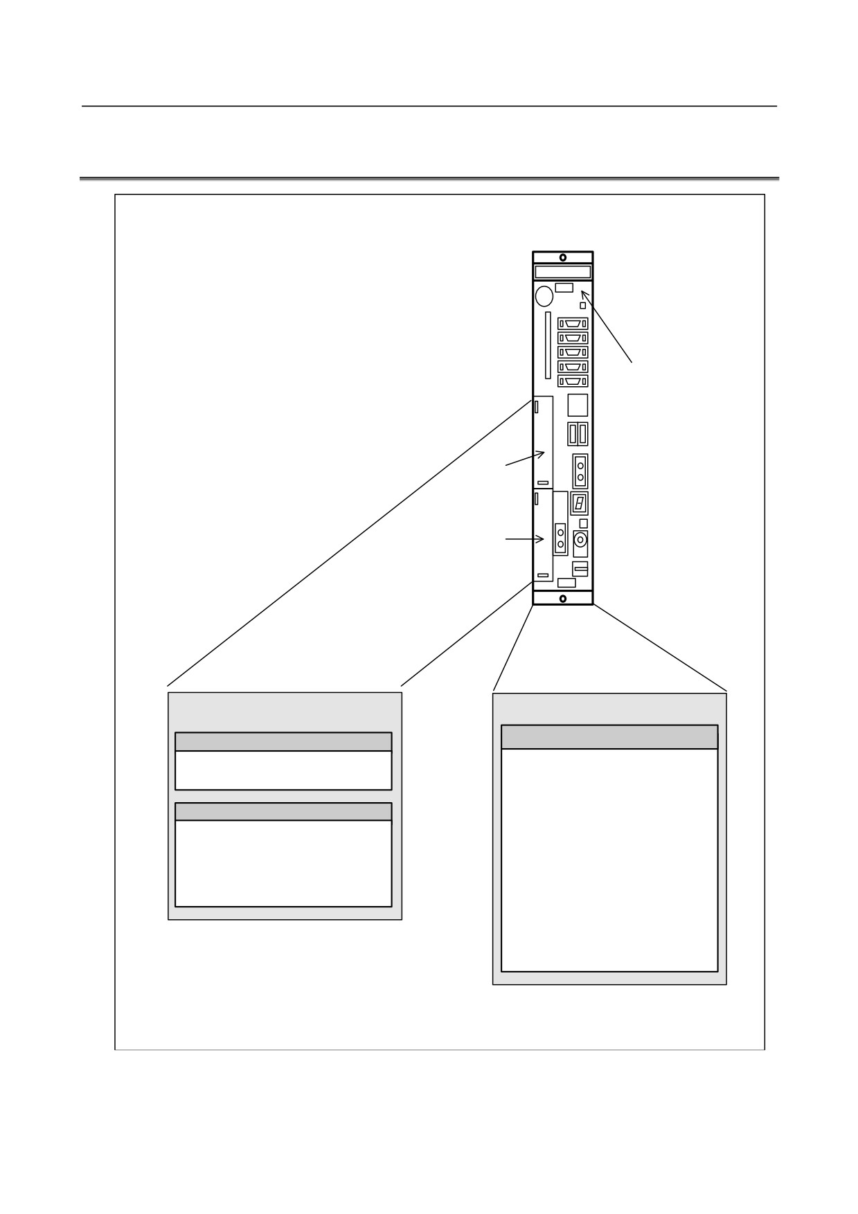
12.3 CONTROL UNIT OVERVIEW
2-slot rack
Main board
Slot 1
Slot 2
Option (slot 1 to 2)
Basic system
Main board
Fast Ethernet board
Data server function
• CPU for controlling CNC
Ethernet communication function
• Power supply
• Axis control
Various types of network boards
• Spindle interface
Profibus master board
• DISPLAY interface
Profibus slave board
• I/O Link
FL-net board
• PMC control function
DeviceNet master board
• High-speed DI
DeviceNet slave board
• RS-232C
• Memory card interface
• Ethernet
- 354 -
B-64303EN/03
12.CONNECTION OF THE STAND-ALONE TYPE
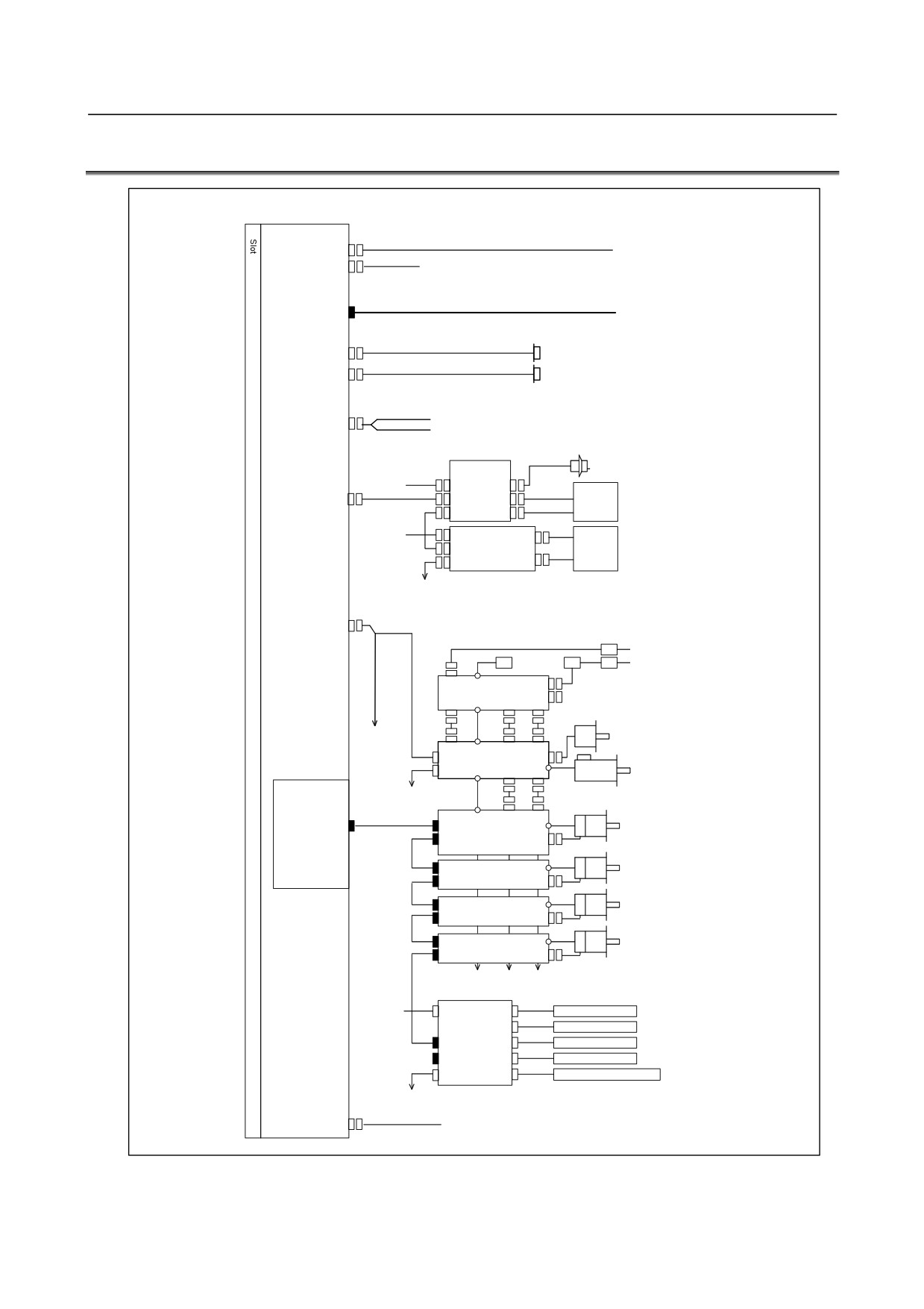
12.4 TOTAL CONNECTION DIAGRAMS
Main board
24V-IN(CPD19A)
24 VDC power supply
24V-OUT(CPD19B)
To I/O device
Optical fiber ccable
PANEL i or personal
DISPLAY(COP21A)
computer
R232-1(JD36A)
RS-232-C I/O device
R232-2(JD36B)
RS-232-C I/O device
Analog putput for tool drive
A-OUT&HDI(JA40)
High-peed skip input
Distributed
Manual pulse generator
I/O board
24VDC
CPD1
JA3
I/O Link(JD51A)
JD1B
Operator's
panel
JD1A
24VDC
CPD1
Distributed
Power
JD1B
I/O board,
magnetics
I/O unit,
JD1A
cabinet
etc.
SPDL(JA41)
Circuit breaker
200VAC
AC reactor
200VAC
MCC
Circuit breaker
αi PS
Position coder
3rd spindle
αi SP
Servo card
To 2nd spindle
Serial spindle motor
Optical fiber cable
FSSB(COP10A-1)
COP10B
Axis 1
αi SV
servo motor
COP10A
Axis 2
COP10B
αi SV
servo motor
COP10A
Axis 3
COP10B
αi SV
servo motor
COP10A
Axis 4
COP10B
αi SV
servo motor
COP10A
(In this figure, a 1-axis amplifier is used.)
Separate detector interface unit 1
24VDC
CP11A
JF101
Linear scale, axis 1
JF102
Linear scale, axis 2
COP10B
JF103
Linear scale, axis 3
COP10AJF104
Linear scale, axis 4
CNF1
JA4A
Battery for absolute scale
(Required only when an absolute scale is used)
Separate detector
interface unit 2
ETHERNET(CD38A)
Ethernet
- 355 -

12.CONNECTION OF THE STAND-ALONE TYPE
B-64303EN/03
12.5 INSTALLATION
12.5.1 Environmental Conditions of the Control Unit
The operating ambient temperature of control unit for the stand-alone type is 0°C to 55°C, which is
different from that of the control unit for the LCD-mounted type.
Ambient temperature
Operating
0°C to 55°C
The other conditions are the same as those of the LCD-mounted type. See the Subsection 3.1.2,
“Environmental Conditions of the Control Unit.”
12.5.2 Power Supply Capacity
The power supply capacity of the control unit for the stand-alone type is shown below. The power
supply capacities of optional boards are the same as those of the LCD-mounted type. Notes on the
power supply capacity are the same as those of the LCD-mounted type. See the Subsection 3.2.1,
“Power Supply Capacities of CNC-related Units.”
Table 12.5.2 Power supply capacity
Unit
Power supply capacity
Remarks
Stand-alone type control unit
Control unit (single)
1.6A
NOTE
See FANUC PANEL i CONNECTION AND MAINTENANCE MANUAL
(B-64223EN), for PANEL i.
12.5.3 Heat Output of Each Unit
The heat output of the stand-alone type control unit is shown below. The heat output of optional boards
is the same as that of the LCD-mounted type.
Table 12.5.3 Heat output
Unit
Heat output
Remarks
Stand-alone type control unit
Control unit (single)
30W
- 356 -
B-64303EN/03
12.CONNECTION OF THE STAND-ALONE TYPE
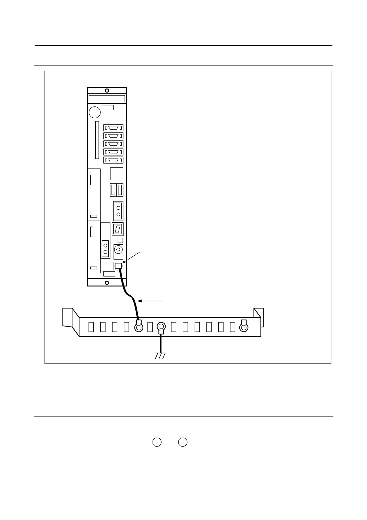
12.5.4 Connecting the Ground Terminal of the Control Unit
For 2-slot rack
Protection ground terminal
(Faston terminal)
Ground cable
2mm2 or more
Grounding plate of
the cabinet
Ì
PE
Connect the 0-V lines of the electronic circuits in the control unit to the ground plate of the cabinet via the
protection ground terminal (above figure).
Use the Faston terminal (FANUC specification: A02B-0166-K330).
12.5.5 Installing the Control Unit
The control unit is equipped with a fan motor.
Air is fed into the bottom of the unit and output from the fan motor mounted on the top of the unit.
The spaces shown in Fig. 12.5.5 (areas A and B ) are always required to ensure smooth air flow.
Also, adequate service access space is required in front of and at the top of the unit so that printed circuit
boards and the fan motor can be replaced easily if necessary.
- 357 -
12.CONNECTION OF THE STAND-ALONE TYPE
B-64303EN/03
There is a spare connector located at the far end (at middle height) on the right side of the control unit.
This connector is used for controller testing and other purposes. Therefore, space
(area C ) for
handling the connector is required.
Space for air flow, and access area for fan replacement
2-slot rack: Approx. 65
30
Approx. 180
50
A
A
Access space for
spare connector
380
C
Spare connector
50
B
B
80
Sufficient space for
replacing a printed circuit
Unit: mm
board is required.
Fig. 12.5.5
12.6 POWER SUPPLY CONNECTION
12.6.1 TURNING ON AND OFF THE POWER TO THE CONTROL UNIT
12.6.1.1 Power-on Sequence
The power-on sequence of the stand-alone type is the same as that of the LCD-mounted type.
The power-on sequence between the PANEL i and the CNC control unit is not defined.
- 358 -
B-64303EN/03
12.CONNECTION OF THE STAND-ALONE TYPE
12.6.1.2 Power-off Sequence
The power-off sequence of the stand-alone type is the same as that of the LCD-mounted type.
The power-off sequence between the PANEL i and the CNC control unit is not defined.
12.6.2 Cable for Power Supply to Control Unit
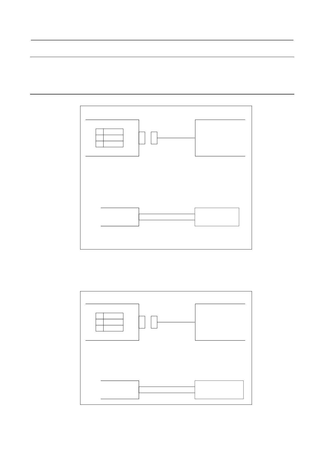
Supply the power to the control unit from an external 24 VDC power supply.
CNC control unit
External power
CPD19A
1
+24V
24VDC stabilized
2
0V
power
3
24VDC±10%
Cable
CPD19A
日本 AMP
1-178288-3 (housing)
1-175218-5 (Contact)
External power
Select a source that
+24V (1)
meets the external
0V (2)
power terminal.
Recommended cable : A02B-0124-K830(5m)
(Crimp terminal of size M3 is available on the external power
side)
As for an stand-alone type control unit, part of the 24 VDC power input to CPD19A can be taken out
from CPD19B by branching. CPD19B should be connected as shown below. In this case, the rating of
the external 24 VDC power supplied to CPD19A must be the sum of the power consumed within the
control unit and that supplied to external equipment via CPD19B. Up to 1.0 A can be supplied to the
external equipment.
CNC control unit
External device
CPD19B
1
+24V
2
0V
3
Cable
CPD19B
AMP Japan
2-178288-3 (Housing)
1-175218-5 (Contact)
External device
Select a connector that
+24V (1)
matches the pin layout
0V (2)
of the external device.
- 359 -
12.CONNECTION OF THE STAND-ALONE TYPE
B-64303EN/03
12.6.3 Batteries
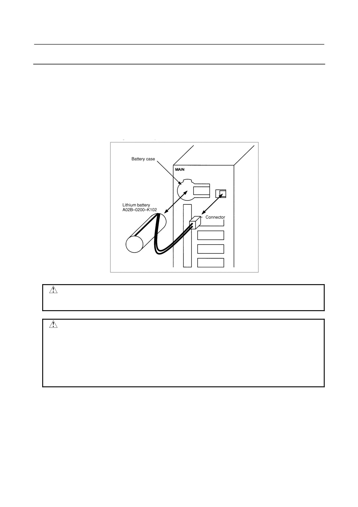
Replacing the battery for stand-alone type control unit
If a lithium battery is used, have A02B-0200-K102 (FANUC internal code: A98L-0031-0012) handy.
1
Turn the CNC on. About 30 seconds later, turn the CNC off.
2
Remove the battery from the top area of the CNC unit.
First, pull the battery cable to unplug the connector. Then, remove the battery from the battery
case.
The battery case is provided in the top area of the face plate of the main board.
3
Replace the battery, then connect the connector.
WARNING
Using other than the recommended battery may result in the battery exploding.
Replace the battery only with the specified battery (A02B-0200-K102).
CAUTION
Steps 1 to 3 should be completed within 30 minutes. Do not leave the control
unit without a battery for any longer than the specified period. Otherwise, the
contents of memory may be lost.
If steps 1 to 3 may not be completed within 30 minutes, save all contents of the
SRAM memory to the memory card beforehand. Thus, if the contents of the
SRAM memory are lost, the contents can be restored easily. For the method of
operation, refer to Maintenance manual.
Discard the dead battery, observing appropriate municipal rules and regulations. When discarding the
battery, insulate the terminal with a tape so that no short-circuit would occur.
- 360 -
B-64303EN/03
12.CONNECTION OF THE STAND-ALONE TYPE
12.7 HIGH-SPEED SERIAL BUS (HSSB)
12.7.1 Overview
The high-speed serial bus (HSSB) enables the high-speed transfer of large amounts of data between a
commercially available IBM PC or compatible personal computer and a CNC, by connecting them via a
high-speed optical fiber.
For a stand-alone type CNC, the HSSB interface is provided as a standard feature.
On the personal computer, an appropriate interface board is installed.
You can use the FANUC PANEL i instead of a commercial PC. The FANUC PANEL i comes standard
with the HSSB interface.
12.7.2 Cautions
The use of the HSSB requires an IBM PC/AT compatible computer or FANUC intelligent terminal. The
machine tool builder or end user is required to procure and maintain the personal computer.
To enable the use of the HSSB, Windows XP must have been installed on the personal computer.
FANUC owns the copyright for the HSSB device driver.
The software mentioned above and the contents of the related manuals may not be used or reproduced in
part or whole without the prior written permission of FANUC.
NOTE
IBM is a registered trademark of IBM Corp. of the US.
Windows XP is registered trademarks of Microsoft Corp. of the US.
The company and product names mentioned in this manual are trademarks or
registered trademarks of the respective companies.
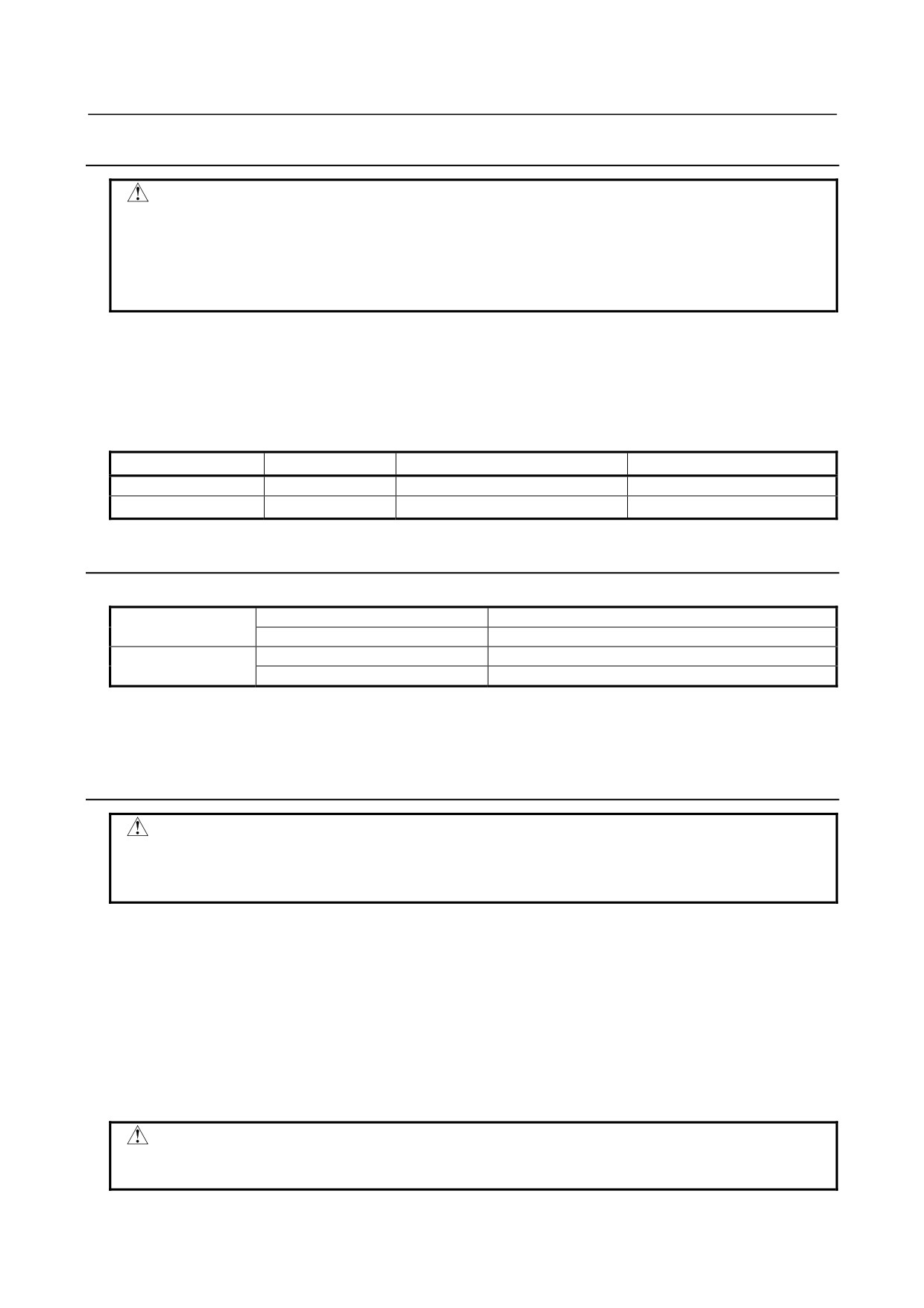
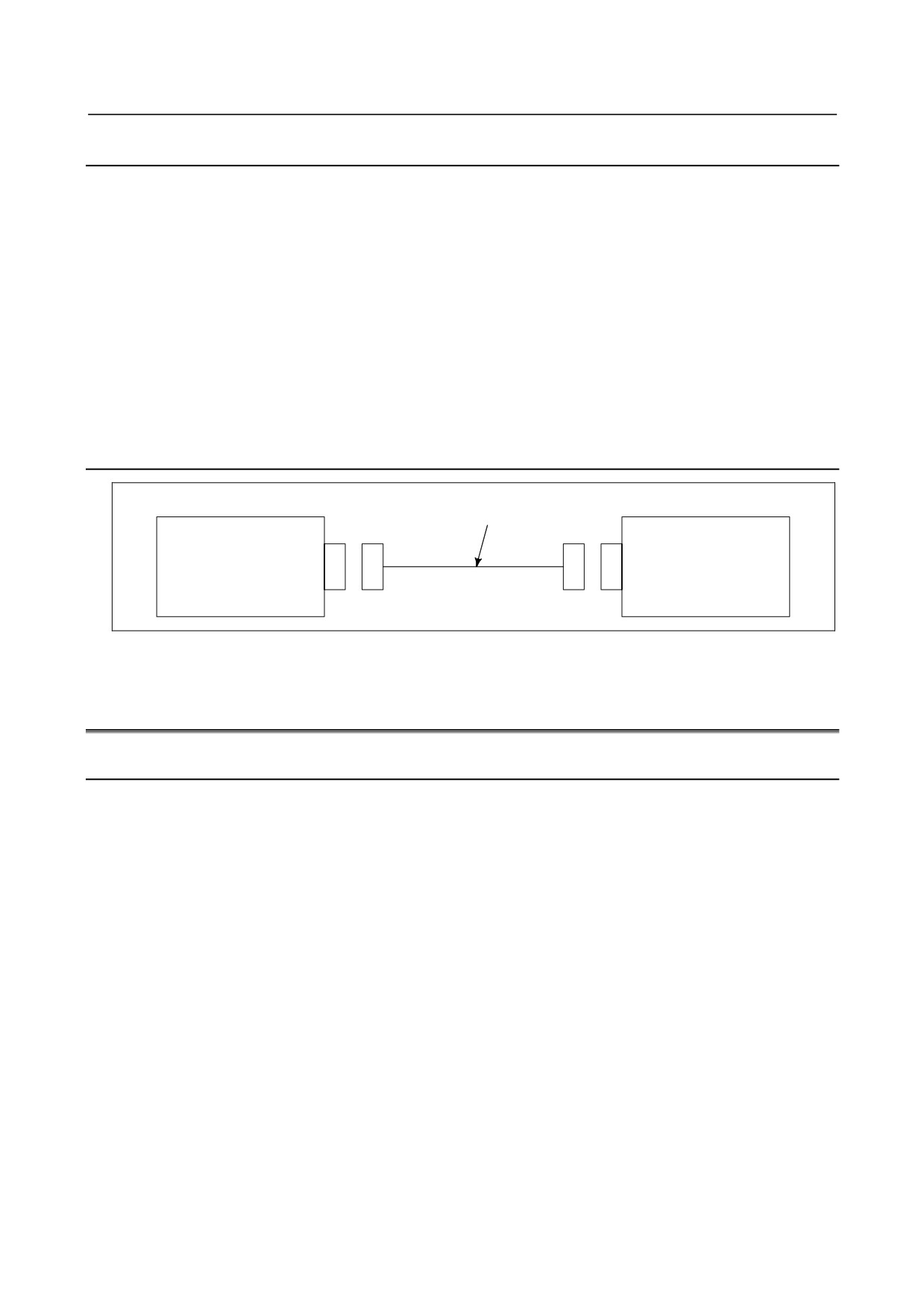
12.7.3 Connection Diagram
Personal computer interface
board (for PCI)
COP21M
Personal computer
COP21A
(on a main board)
COP21M
Stand-alone type control unit
PANEL i
Note: Only an interface board for the PCI bus is provided as the interface board to
be installed in the personal computer.
- 361 -
12.CONNECTION OF THE STAND-ALONE TYPE
B-64303EN/03
12.7.4 Personal Computer Specification
CAUTION
1 The machine tool builder or end user is required to procure and maintain the
personal computer.
2 FANUC is not liable for any problems resulting from the operation of users'
personal computers, regardless of whether the operations are normal or
abnormal.
(1) The personal computer must have a PCI slot (5 V).
(2) When this board is used, an HSSB driver must be installed in the personal computer.
(3) Please examine the connection test including the communication between the personal computer and
CNC controller sufficiently.
(4) Following shows the required power of the interface board for PCI type.
Drawing No.
Specification
Power supply requirements
Remarks
A20B-8101-0162
2ch specification
+5V 1.5A
A20B-8101-0163
1ch specification
+5V 1A
12.7.5 Installation Environment
HSSB Interface Board For Personal Computer
Ambient temperature
Operating
0 to 55 °C
Non-operating
-20 to 60 °C
Humidity
Usual
10 to 75% (non-condensing)
Short-term (within one month)
10 to 95% (non-condensing)
If the environmental requirement of the using personal computer is different from the above, please
keep the environmental requirement to be satisfied by the both equipments.
12.7.6 Procedure for Installing Personal Computer Interface Boards
WARNING
Before starting to mount or remove a personal computer interface board, switch
off the personal computer and its peripheral devices, and disconnect their power
supply cables. Otherwise, there is a serious danger of electric shock.
(1) Remove the covering plate of extension slot on the personal computer.
(2) Insert the interface board for the personal computer to the PCI connector tightly.
(3) Screw the plate of interface board to the computer.
(4) Confirm connection (in only case of HSSB multi-connection)
Confirm following items for installing drivers of HSSB interface board in case of HSSB
multi-connection.
-
PCI slot number which HSSB board is mounted (slot number is marked to PCB normally).
-
Correspondence between HSSB channel and CNC
(5) Restore the covering plate.
CAUTION
Do not touch the leads running to the card edge of the interface board (that
match with connectors).
- 362 -
B-64303EN/03
12.CONNECTION OF THE STAND-ALONE TYPE
12.7.7 Handling Precautions
(1) Personal computer interface board
(a) Electrostatic interference
The personal computer interface board is shipped in an anti-static bag. To store or transport
the interface board, always place it in the anti-static bag. Before removing the interface board
from the anti-static bag, ground your body.
(b) Protection of card edge terminals
When handling the personal computer interface board, do NOT touch its card edge terminals
(the gold-plated contacts which engage with a mating connector). If you accidentally touch
any card edge terminal, wipe it gently with clean or ethyl alcohol-dipped tissue paper or
absorbent cotton. Do not use any organic solvent other than ethyl alcohol.
(2) Optical connector and fiber cable
See Appendix D, “OPTICAL FIBER CABLE.”
12.7.8 Recommended Cables
CNC side HSSB interface board
Personal computer interface card
Optical fiber cable
COP21A
COP21M
For the available optical fiber cables, see Appendix D.
12.8 PERIPHERAL EQUIPMENT AND CONNECTION
12.8.1 Connection with the MDI Unit
When using the MDI unit together with the stand-alone type, connect the MDI unit to the FANUC
PANEL i. For details on the connection, refer to the FANUC PANEL i Connection and Maintenance
Manual (B-64223EN).
- 363 -
12.CONNECTION OF THE STAND-ALONE TYPE
B-64303EN/03
12.9 EXTERNAL DIMENSIONS OF EACH UNIT
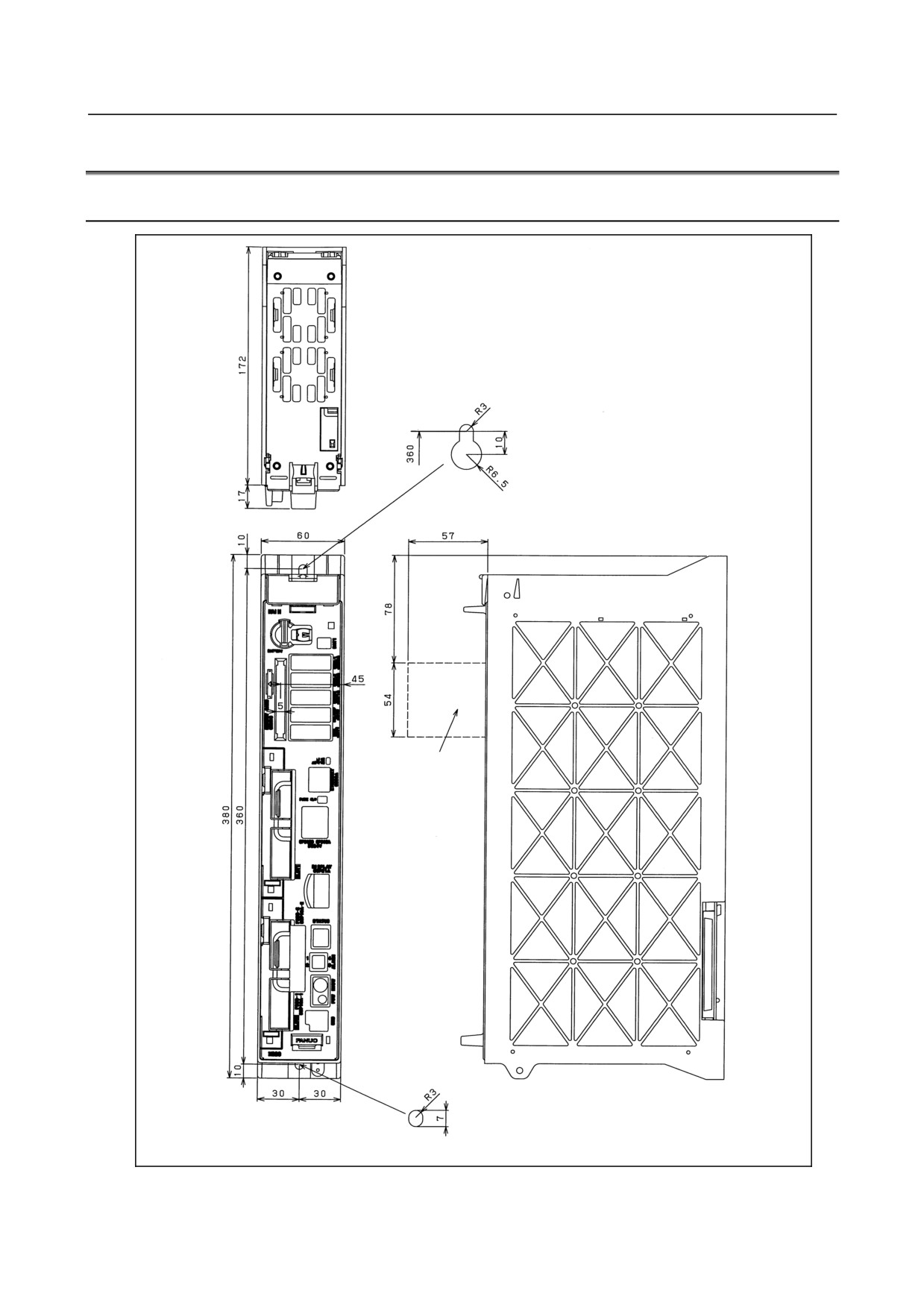
12.9.1 External Dimensions of Stand-alone type Control Unit
Memory
card
Weight: 1.7kg
(Unit: mm)
- 364 -
B-64303EN/03
12.CONNECTION OF THE STAND-ALONE TYPE
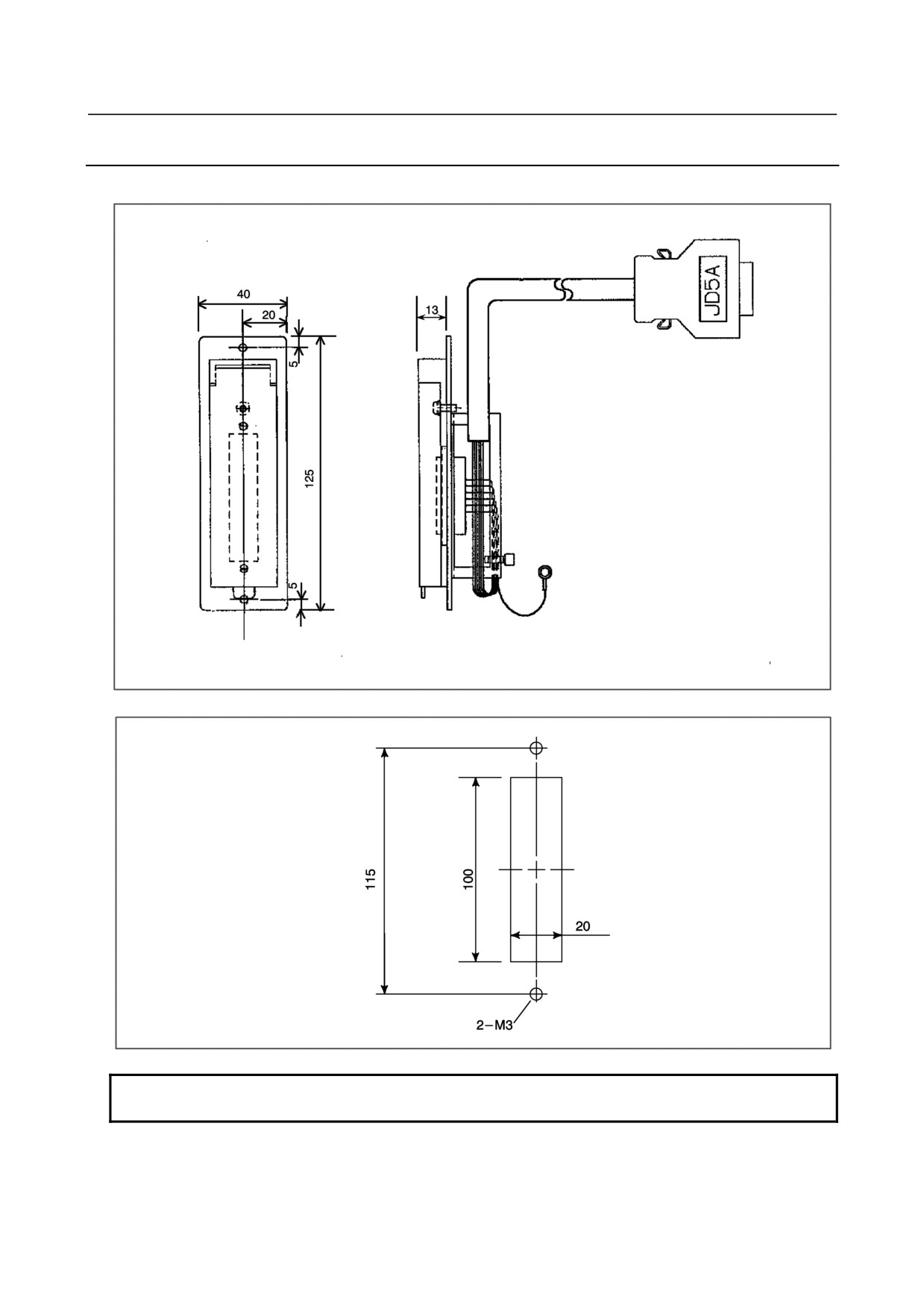
12.9.2 Punch Panel (for Stand-alone Type Control Unit)
Specification: A02B-0120-C191,C192,C193
A paint masking zone 8 mm wide is provided on the periphery of the rear
of the plate.
The panel cut dimensions of this punch panel are indicated below.
NOTE
This punch panel cannot used for the PANEL i.
- 365 -
APPENDIX
A.EXTERNAL DIMENSIONS
B-64303EN/03
APPENDIX
OF EACH UNIT
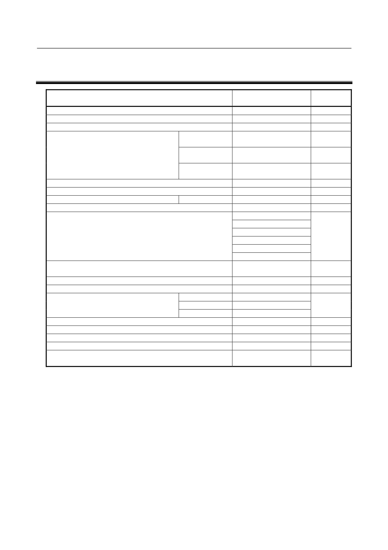
A EXTERNAL DIMENSIONS OF EACH UNIT
Specification drawing
Outline drawing name
Fig.
number
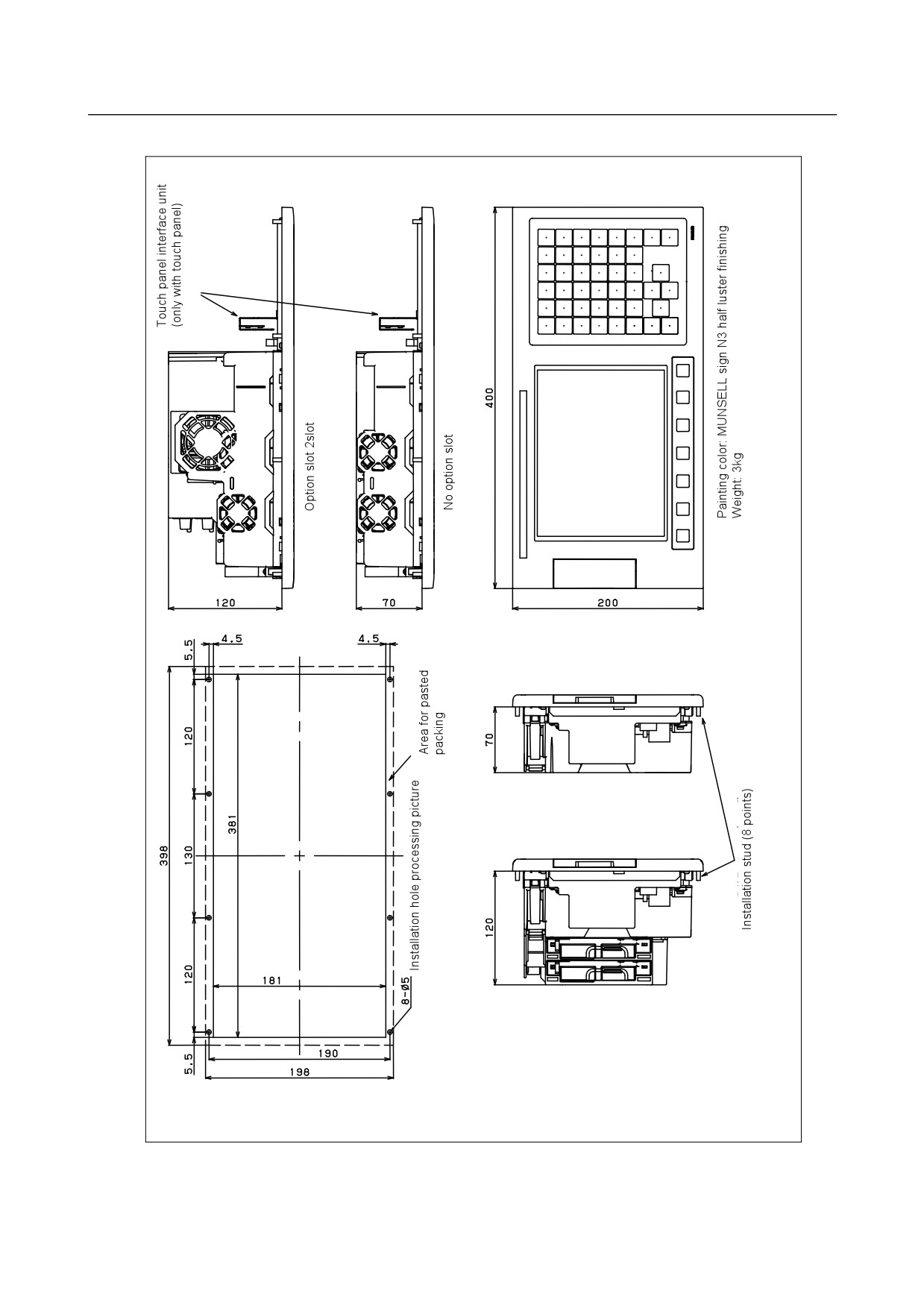
CNC control unit (8.4” color LCD/MDI horizontal type)
Fig. U1
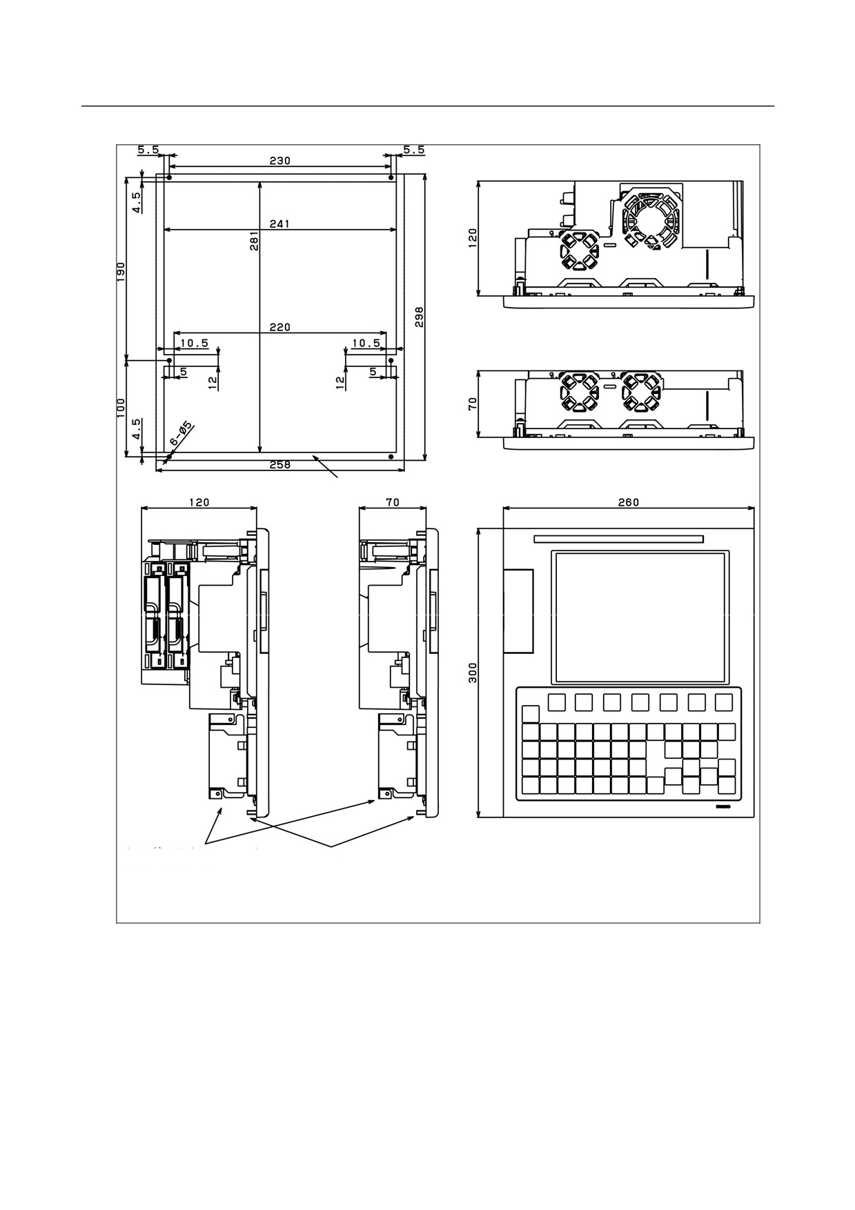
CNC control unit (8.4” color LCD/MDI vertical type)
Fig. U2
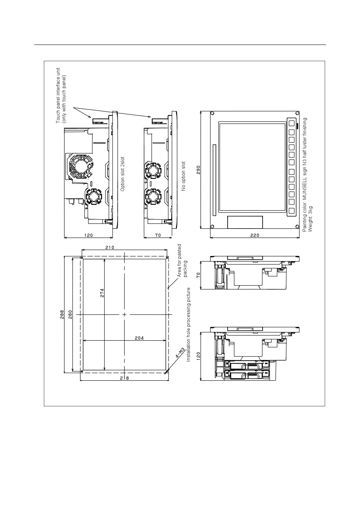
CNC control unit (10.4” color LCD)
Fig. U3
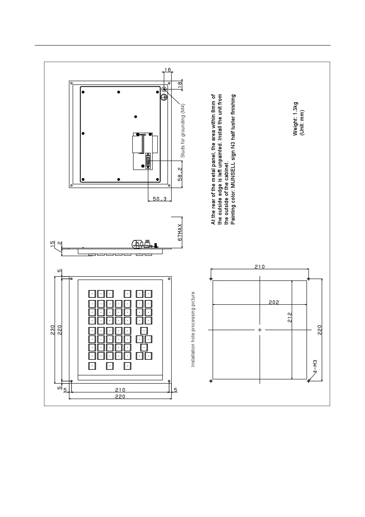
MDI unit
Horizontal type
A02B-0319-C125#T,
Fig. U4 (a)
A02B-0319-C125#M
Vertical type
A02B-0319-C126#T,
Fig. U4 (b)
A02B-0319-C126#M
Small type
A02B-0303-C120#T,
Fig. U4 (c)
A02B-0303-C120#M
Portion in which each CNC control unit is installed
Fig. U6
I/O unit for 0i
A02B-0309-C001
Fig. U7
αi position coder
10000 min-1
A860-2109-T302
Fig. U17
Manual pulse generator
A860-0203-T001
Fig. U18
Pendant type manual pulse generator
A860-0203-T004
Fig. U19
A860-0203-T005
A860-0203-T007
A860-0203-T010
A860-0203-T012
A860-0203-T013
Separate detector interface unit
A02B-0303-C205
Fig. U20
A02B-0236-C204
Battery case for separate detector interface unit (ABS)
A06B-6050-K060
Fig. U21
CNC battery unit for external installation
A02B-0236-C282
Fig. U22
Punch panel Narrow width type
Cable length: 1m
A02B-0236-C191
Fig. U24
Cable length: 2m
A02B-0236-C192
Cable length: 5m
A02B-0236-C193
Machine operator's panel: Main panel A
A02B-0319-C242
Fig. U25
Machine operator's panel: Main panel B
A02B-0319-C243
Fig. U26
Machine operator's panel: Sub panel A
A02B-0236-C232
Fig. U27
Machine operator's panel: Sub panel B1
A02B-0236-C235
Fig. U28
Screw cap (for small MDI unit)
A02B-0303-K190,
Fig. U29
A02B-0303-K191
- 369 -
A. EXTERNAL DIMENSIONS
OF EACH UNITTABLE
APPENDIX
B-64303EN/03
Fig. U1
CNC control unit (8.4” color LCD/MDI horizontal type)
NOTE The unit is installed from outside cabinet.
Fix with M4 nut from the reverse side. The tightening torque is 2.0 N⋅m.
- 370 -
A.EXTERNAL DIMENSIONS
B-64303EN/03
APPENDIX
OF EACH UNIT
Fig. U2
CNC control unit (8.4” color LCD/MDI vertical type)
Installation hole
processing picture
Option slot 2slot
No option slot
Area for pasted packing
Painting color: MUNSELL sign N3 half luster finishing
Weight: 3kg
Touch panel interface unit
Installation stud (8 points)
(only with touch panel)
NOTE The unit is installed from outside cabinet.
Fix with M4 nut from the reverse side. The tightening torque is 2.0 N⋅m.
- 371 -
A. EXTERNAL DIMENSIONS
OF EACH UNITTABLE
APPENDIX
B-64303EN/03
Fig. U3
CNC control unit (10.4” color LCD)
NOTE The unit is stopped with the screw from outside of the cabinet, then
install the screw cap.
The unit with a touch panel has no soft keys.
- 372 -
A.EXTERNAL DIMENSIONS
B-64303EN/03
APPENDIX
OF EACH UNIT
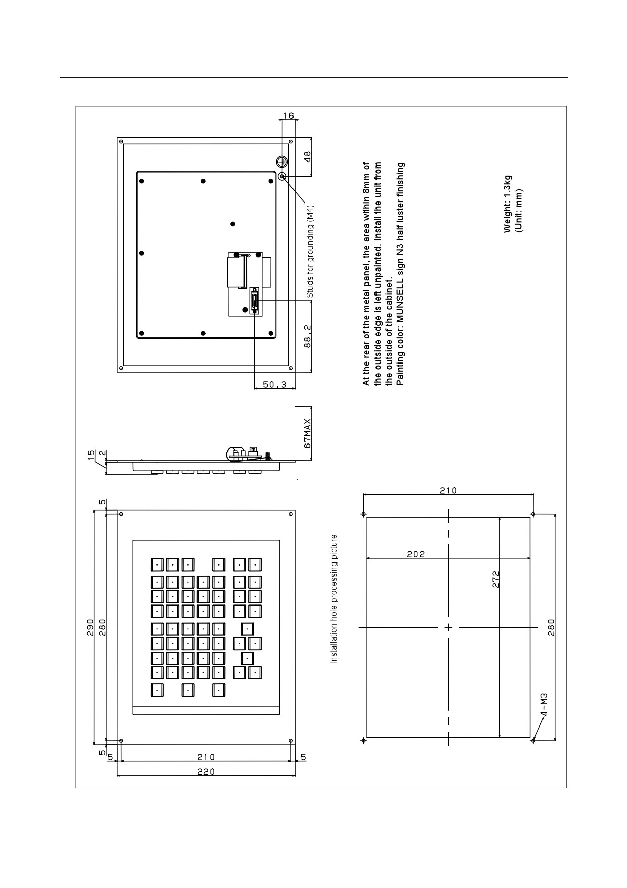
Fig. U4(a) MDI unit (horizontal type)
- 373 -
A. EXTERNAL DIMENSIONS
OF EACH UNITTABLE
APPENDIX
B-64303EN/03
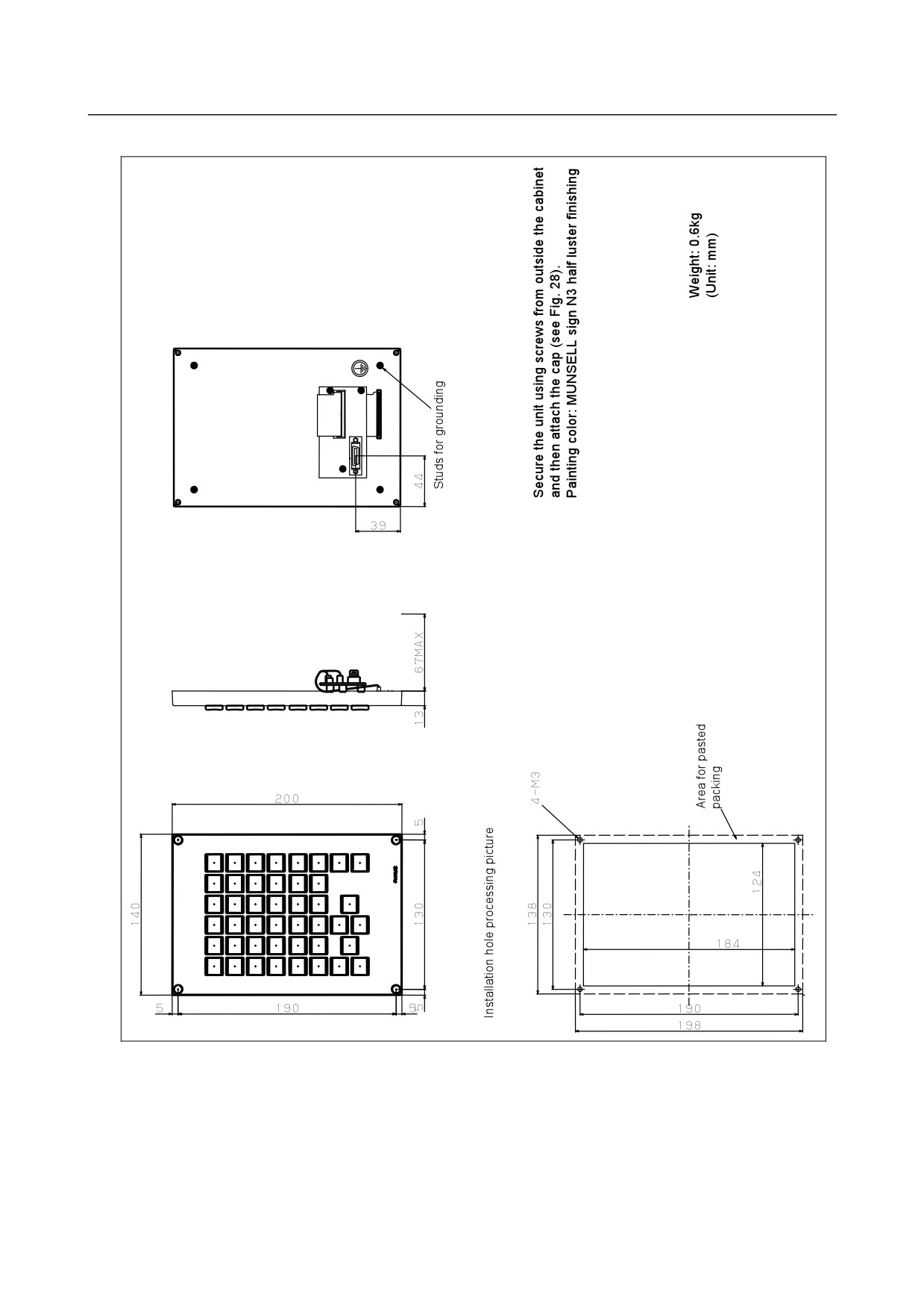
Fig. U4(b) MDI unit (vertical type)
- 374 -
A.EXTERNAL DIMENSIONS
B-64303EN/03
APPENDIX
OF EACH UNIT
Fig. U4(c) MDI unit (small type)
- 375 -
A. EXTERNAL DIMENSIONS
OF EACH UNITTABLE
APPENDIX
B-64303EN/03
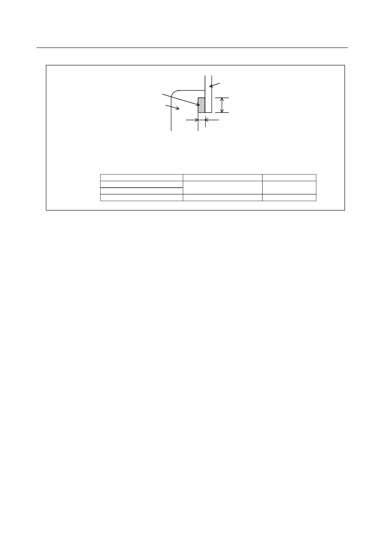
Fig. U6
Portion in which each CNC control unit is installed
Operator's panel sheet metal
Packing
Unit
Width
Installation margin (thickness)
CAUTION
When installing the control unit, be sure to seal between the unit and the operator’s panel with packing.
For the installation margin (thickness) and width, see the table below.
Display unit type
Installation margin (thickness)
Width
8.4" color LCD/MDI (horizontal type)
0.8mm
8.5mm
8.4" color LCD/MDI (vertical type)
10.4" color LCD
0.8mm
7mm
- 376 -