FANUC Series 16 / 160 / 18 / 180 – Model B. Maintenance Manual - page 2
B-62445E/03
1. DISPLAY AND OPERATION OF CRT/MDI
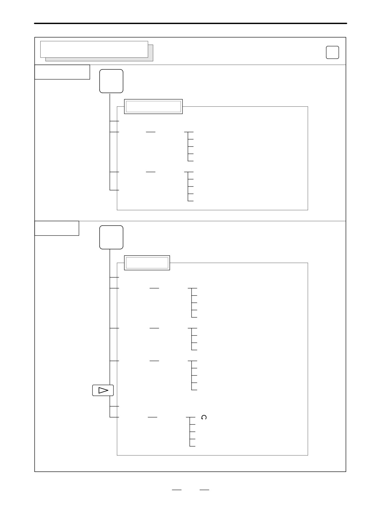
GRAPHIC SCREEN (M series)
Soft key transition triggered by the function key
GRAPH
Tool path graphics
GRAPH
Tool path graphics
[PARAM]
[EXEC]
[(OPRT)]
[AUTO]
[STSRT]
[STOP]
[REWIND]
[CLEAR]
[ZOOM]
[(OPRT)]
[EXEC]
[←]
[→]
[POS]
[↑]
[↓]
Solid graphics
GRAPH
Solid graphics
[PARAM]
[BLANK]
[(OPRT)]
[ANEW]
[+ROT]
[-ROT]
[+TILT]
[-TILT]
[EXEC]
[(OPRT)]
[A.ST]]
[F.ST]
[STOP]
[REWIND]
[REVIEW]
[(OPRT)]
[ANEW]
[+ROT]
[-ROT]
[+TILT]
[-TILT]
[PARAM]
[3-PLN]
[(OPRT)]
[
]
[←]
[→]
[↑]
[↓]
21
1. DISPLAY AND OPERATION OF CRT/MDI
B-62445E/03
1.2
SCREEN DISPLAYED
IMMEDIATELY AFTER
POWER IS TURNED
ON
1.2.1
Slot Status Display
Types of PCBs mounted on the slots are displayed.
If a hardware trouble or an incorrect mounting is found, this screen is
displayed.
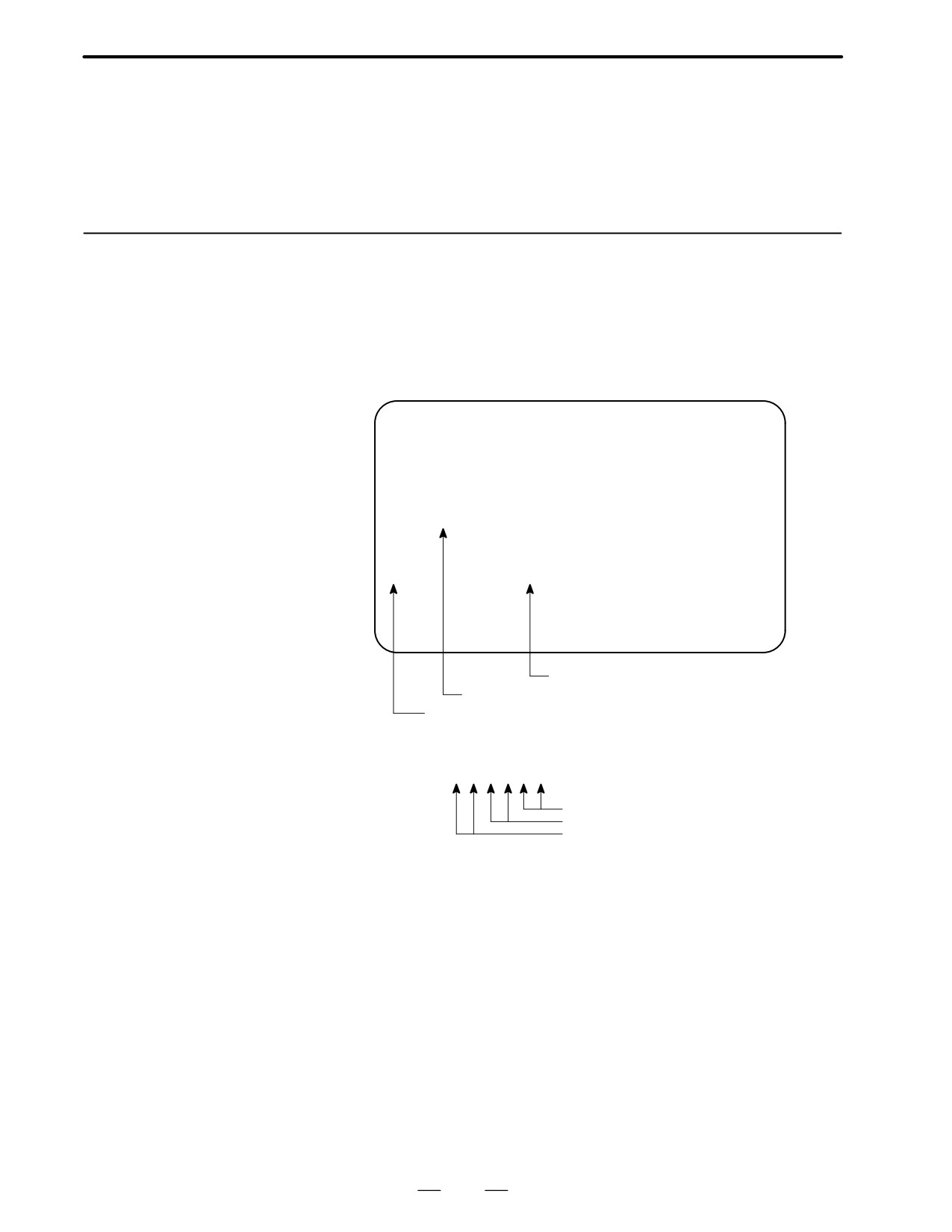
D Slot state screen
SLOT CONFIGURATION DISPLAY
0: 003E4000
0:
1: 30464202
1:
2: 00504303
2:
3:
3:
4:
4:
5:
5:
…
…
Physical slot number (2ndary side)
Module ID of the PCB mounted (*1)
Physical slot number (primary side)
*1) Module ID of PCB
××f f j j Δ Δ
Internal slot number
Module function (software ID)
Type of PCB (module ID)
D Module ID
90 : Series 16 main CPU (For 4-axis)
9C : Series16 option 2
B2 : Series 16 main CPU (For 4-axis) B7 : Series16 option 2
A7 : Series 16 main CPU (For 6-axis) B0 : Series16/18 option 2
AD : Series 18 main CPU (For 4-axis)
AE : Series 18 main CPU (For 6-axis)
3F : Remote buffer DNC1
90 : PMC-RC
46 : I/O card (Sink type)
5F : I/O card (Source type)
A8 : I/O card with power supply (Sink type)
B1 : I/O card with power supply (Source type)
6D : CAP-II
45 : Graphic (CAP-II)
9A : Graphic
22
B-62445E/03
1. DISPLAY AND OPERATION OF CRT/MDI
D Software ID
40 : Main CPU
49 : CAP II
41 : Option 3 board
4A : Remote buffer
42 : Built-in I/O card
43 : Sub CPU
4E :
4F :
45 : Graphic
50 : Additional 4-axis control (FS16 option 2)
46 : Graphic (CAP II)
1.2.2
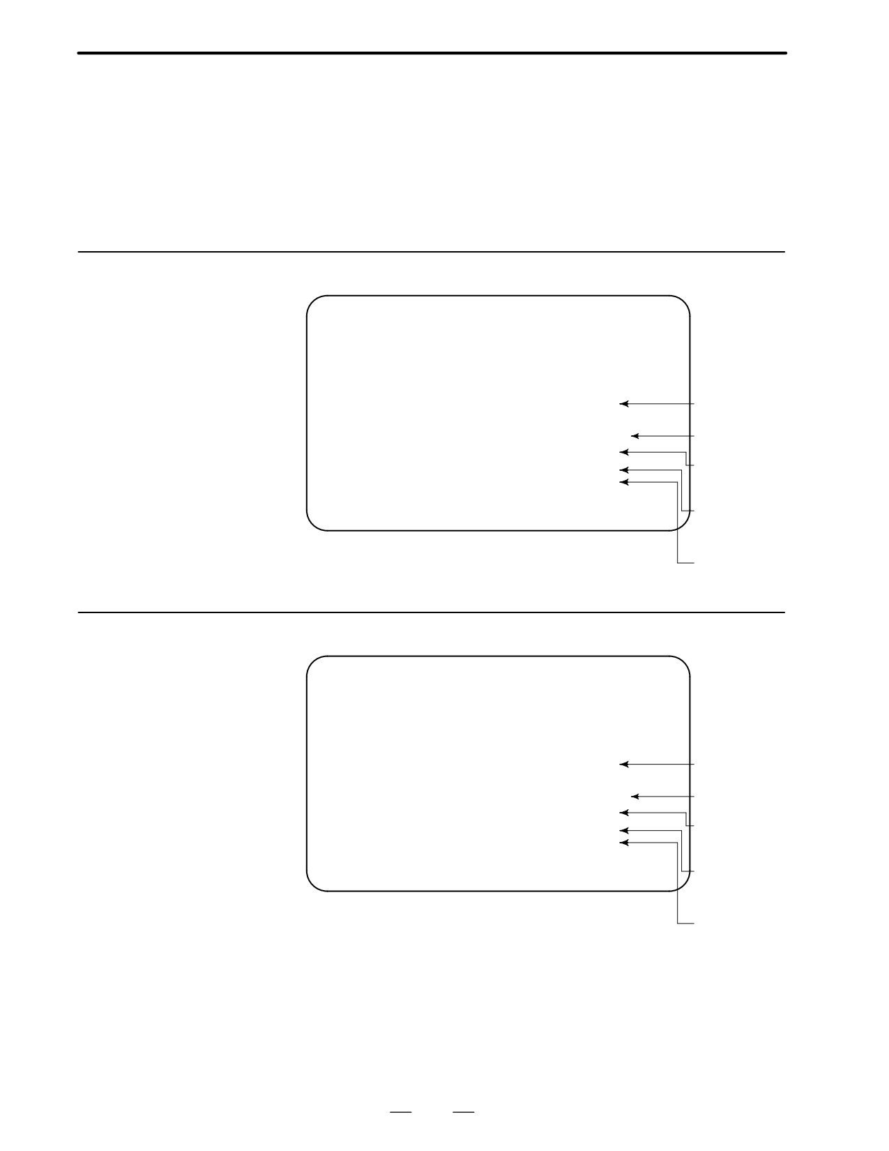
Setting Module Screen
CNC control
B0A1-01
software
SERVO : 9060-01
Digital servo
ROM
SUB : xxxx-xx
OMM : yyyy-yy
Sub CPU
(Remote buffer)
PMC : zzzz-zz
Order made
macro/macro
compiler
PMC
1.2.3
Configuration Display
of Software
CNC control
B0A1-01
software
SERVO : 9060-01
Digital servo
ROM
SUB : xxxx-xx
Sub CPU
OMM : yyyy-yy
(Remote buffer)
PMC : zzzz-zz
Order made
macro/macro
compiler
PMC
23
1. DISPLAY AND OPERATION OF CRT/MDI
B-62445E/03
After the system has been installed correctly, you can find the PCBs
1.3
installed and the softwares integrated on the system configuration screen.
SYSTEM
CONFIGURATION
SCREEN
1.3.1
SYSTEM
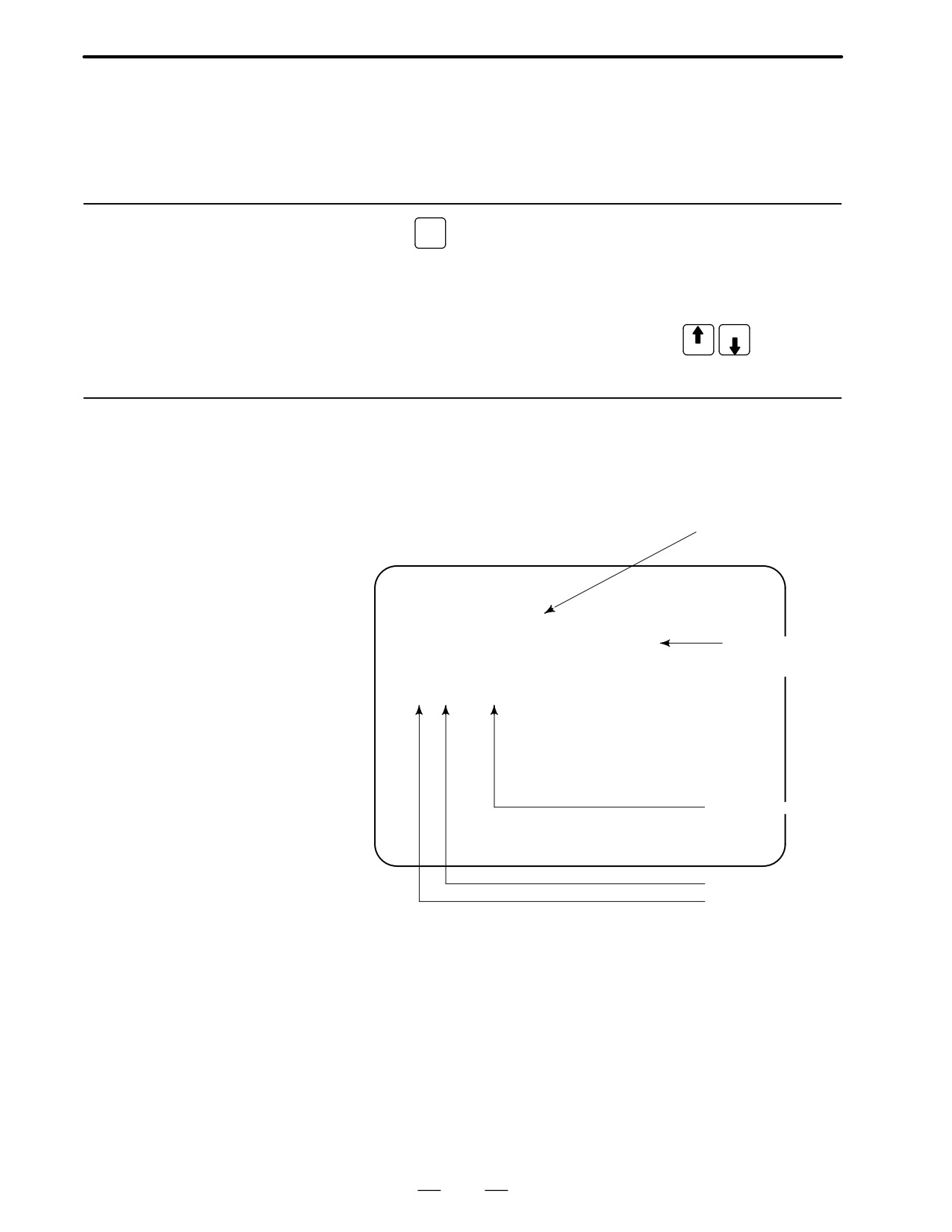
(1) Press
key.
Display Method
(2) Press soft key
[system],then the system configuration screen is
displayed.
(3) The system configuration screen is composed of three screens and
PAGE
each of them can be selected by the page key
PAGE
1.3.2
Configuration of PCBs
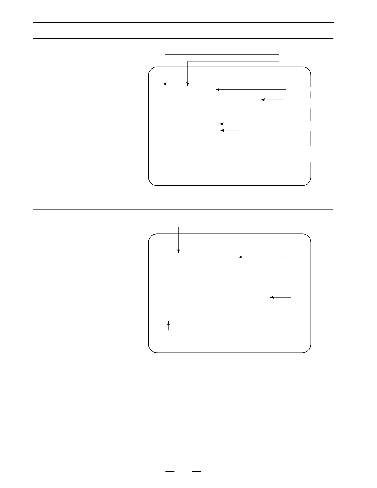
D Screen
Software series of mod-
ule with CPU
SYSTEM CONFIG (SLOT)
PAGE01
SLOT MODULE ID SERIES VERSION
00 0090 : 40
B0A1
0006
Software version
of module with
0D 009A : 45
600E
0003
CPU
02 013F : 4A
B401
0001
03 019D : 41
4068
0001
Software ID (type)
Module ID
Slot No.
(80X8F is 2nd side)
24
B-62445E/03
1. DISPLAY AND OPERATION OF CRT/MDI
D Module ID
90 :
Series 16 main CPU (For 4-axis)
9C : Series16 option 2
B2 : Series 16 main CPU (For 4-axis) B7 : Series16 option 2
A7 : Series 16 main CPU (For 6-axis) B0 : Series16/18 option 2
AD : Series 18 main CPU (For 4-axis)
AE : Series 18 main CPU (For 6-axis)
3F :
Remote buffer DNC1
90 :
PMC-RC
46 :
I/O card (Sink type)
5F :
I/O card (Source type)
A8 : I/O card with power supply (Sink type)
B1 : I/O card with power supply (Source type)
6D : CAP-II
45 :
Graphic (CAP-II)
9A : Graphic
D Software ID
40 :
Main CPU
49 : CAP II
41 :
Option 3 board
4A : Remote buffer
42 :
Built-in I/O card
43 : Sub CPU
4E :
MAP
4F :
45 :
Graphic
50 :
Additional 4-axis control (FS16 option 2)
46 :
Graphic (CAP-II)
25
1. DISPLAY AND OPERATION OF CRT/MDI
B-62445E/03
1.3.3
Kind of software
Software Configuration
Software series
Screen
SYSTEM CONFIG(SOFTWARE)
Software version
SYSTEM BD11
0001
FC1A FC2A F81A F82A
Software
F41A F42A F01A F02A
configuration
SERVO
9050
0001
PMC
4062
0001
LADDER
FS16
0001
Character written on
PMC title screen
MACRO
BBBB
bbbb
Character written
on macro compiler
and on CAP.
1.3.4
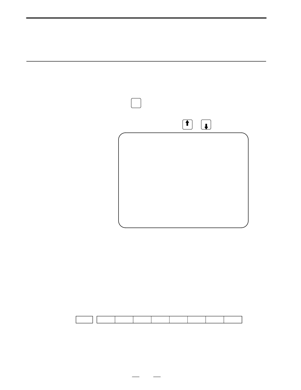
Configuration of the modules displayed on PCB.
(1)
Module Configuration
Screen
SYSTEM CONFIG(MODULE)
(2)
SLOT
00 MAIN CPU BOARD
FLASH ROM MODULE
:
6MB
DRAM MODULE
: 6MB
ADDITIONAL SRAM
: ___
PMC MODULE
: PMP+SLC
CRTC MODULE
: 9ICRT
SERVO
1/2 AXIS MODULE : MOUNTED
(4)
SERVO
3/4 AXIS MODULE : ___
SERIAL SPINDLE LSI
: MOUNTED
ANALOG SPINDLE LSI
: ___
(3)
EDIT **** *** ***
16:53:44
[ PARMA ][ DGNOS ][ PMC ][ SYSTEM ][
]
Contents of display
(1) Slot number (The number is corresponding to PCB configuration
screen)
(2) Type of PCB mounted
(3) Type of mounted module or hardware
(4) Mounted or not, or type of module
Pressing the PAGE key displays the system configuration screen of
other PCBs.
*Refer to ”Construction of Control Unit PCB” for correspondence
with each module and display.
26
B-62445E/03
1. DISPLAY AND OPERATION OF CRT/MDI
1.4
ALARM HISTORY
SCREEN
1.4.1
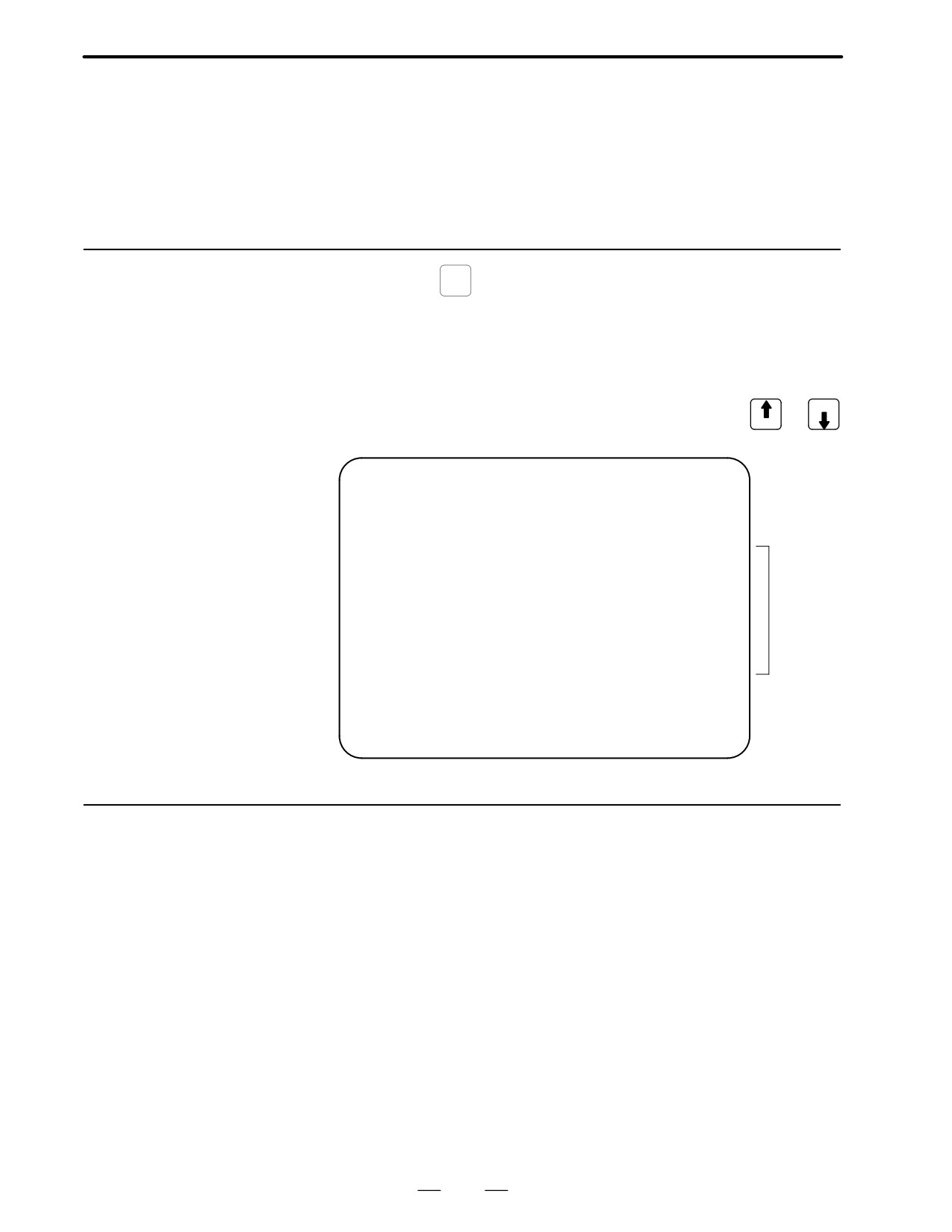
Alarms generated in the NC are recorded. The latest 25 alarms generated
are recorded. The 26th and former alarms are deleted.
General
1.4.2
Screen Display
MESSAGE
(1) Press
key .
(2) Press soft key [HISTRY] and an alarm history screen is displayed.
PAGE
(3) Other pages are displayed by
or
key.
PAGE
ALARM HISTORY
O1234 N12345
91/04/18 20:56:26
506 OVERTRAVEL :
+X
91/04/18 19:58:11
000 TURN OFF POWER
91/04/18 19:52:45
000 TURN OFF POWER
91/04/18 19:48:43
300 APC ALARM
: X-AXIS ZERO RETURN REQUEST
91/04/18 18:10:10
507 OVERTRAVEL :
+B
[ ALARM ][ MSG ][ HISTRY ][
][ (OPE) ]
1.4.3
(1) Press soft key [(OPE)].
Clearing Alarm History
(2) Press soft key [(CLEAR], then the alarm history is cleared.
1.4.4
When an external alarm (No. 1000 to 1999) or a macro alarm (No. 3000
to 3999) is output, the alarm history function can record both the alarm
Alarm Display
number and message if so specified in the following parameter. If
recording of the message is not set or if no message is input, only an
external alarm or macro alarm is displayed.
#7
#6
#5
#4
#3
#2
#1
#0
3112
EAH
[Data type] Bit
#3 (EAH) The alarm history function:
0 : Does not record the messages output with external alarms or macro
alarms.
1 : Records the messages output with external alarms or macro alarms.
27
1. DISPLAY AND OPERATION OF CRT/MDI
B-62445E/03
1.5
This function enables the saving of external operator messages as a
EXTERNAL
record.
OPERATOR
The record can be viewed on the external operator message history screen.
MESSAGES
RECORD
1.5.1
(1) Press the
MESSAGE
function key.
Screen Display
(2) Press the rightmost soft key [>>].
[ALARM] [MGS] [HISTRY] [
] [ (OPRT) ]>>
↑
(3) Press the [MSGHIS] soft key.
(4) To display the previous or subsequent screen, press the
or PAGE
PAGE
key.
MESSAGE HISTORY
O1234 N12345
→ Date, time, and page
→ Message No.
93/04/01 17:25:00
PAGE : 1
No. ****
Up to 255 characters
Display range
MEM STRT MTN FIN ALM 17:25:00
[
][ MSGHIS ][
][
][
]
1.5.2
Deletion of External
(1) The recorded external operator message can be deleted by setting the
MMC bit (bit 0 of parameter 3113) to 1.
Operator Messages
Pressing the [CLEAR] soft key erases all the records of the external
Record
operator message.
(2) The MS1 and MS0 bits (bits 7 and 6 of parameter 3113) specify the
number of records to be displayed on the external operator message
history screen. When the bits are changed, all external operator
message records retained up to that point are erased.
28
B-62445E/03
1. DISPLAY AND OPERATION OF CRT/MDI
1.5.3
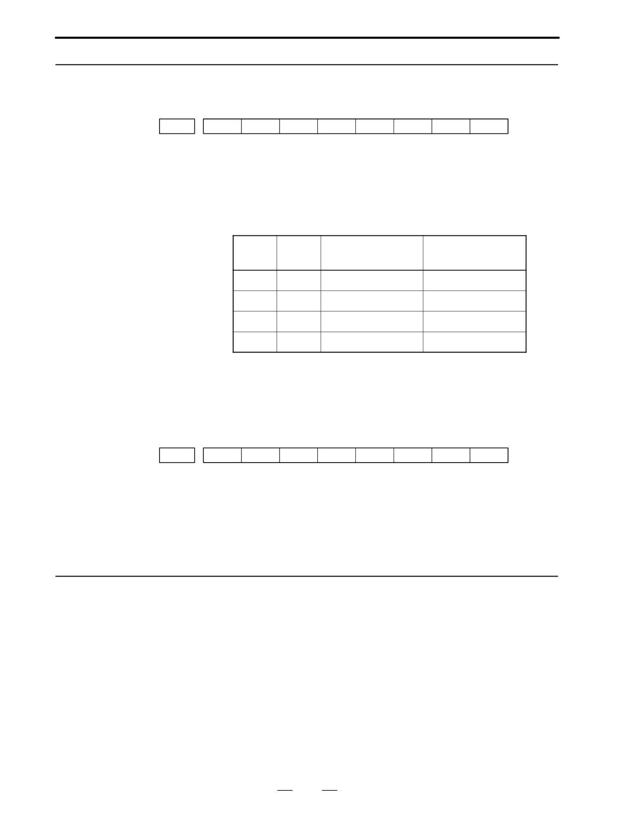
Parameter
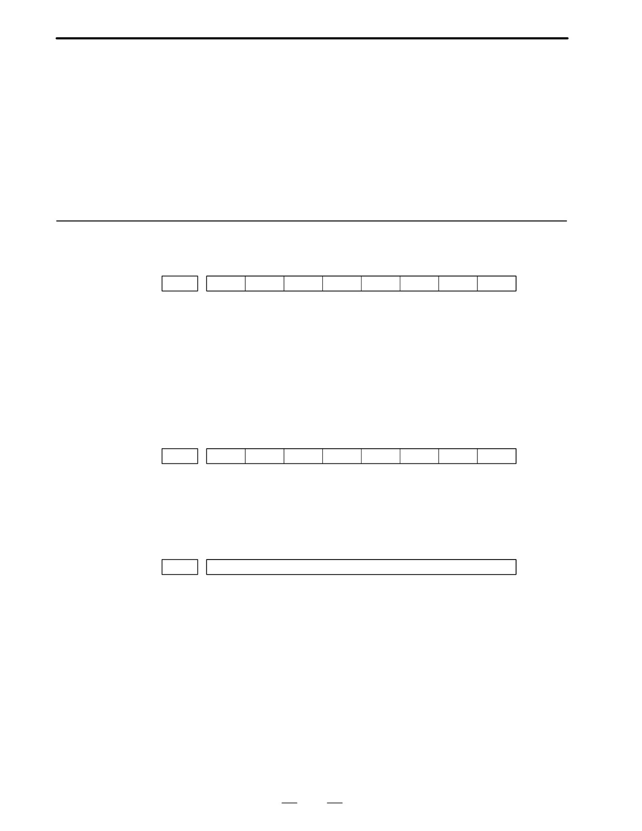
#7
#6
#5
#4
#3
#2
#1
#0
3113
MS1
MS0
MHC
#0 (MHC)
The records of an external operator message:
0 : Cannot be erased.
1 : Can be erased.
MS0,MS1
These bits set the number of characters to be retained in each record of an
external operator message, as well as the number of records, as shown in
the following table:
MS1
MS0
Number of charac-
Number of records
ters in each record
0
0
255
8
0
1
200
10
1
0
100
18
1
1
50
32
* An external operator message of up to 255 characters can be specified.
Combining the MS1 bit and MS0 bit (bits 7 and 6 of parameter No.
3113) selects the number of records by limiting the number of
characters to be retained as the record of an external operator message.
#7
#6
#5
#4
#3
#2
#1
#0
3112
OMH
#2 (OMH)
The external operator message history screen is:
0 : Not displayed.
1 : Displayed.
Note) After setting this parameter, briefly turn the power off, then on
again.
1.5.4
When the number of an external operator message is specified, the system
starts updating the records of the specified message. The system
Notes
continues to perform update until another external operator message is
specified or until an instruction to delete the records of the external
operator message is specified.
29
1. DISPLAY AND OPERATION OF CRT/MDI
B-62445E/03
This function displays the key and signal operations performed by the NC
1.6
operator upon the occurrence of a fault or the output of an NC alarm,
OPERATION HISTORY
together with the corresponding NC alarms.
This function records the following data:
(1) MDI key operations performed by the NC operator
(2) Status changes (ON/OFF) of input and output signals (selected signals
only)
(3) Details of NC alarms
(4) Time stamp (date and time)
1.6.1
Parameter Setting
#7
#6
#5
#4
#3
#2
#1
#0
3106
OHS
OPH
[Data type]
Bit
#4 (OPH)
The operation history screen is:
0 : Not displayed.
l
1 : Displayed.
#7 (OHS)
The operation history is:
0 : Sampled.
1 : Not sampled.
#7
#6
#5
#4
#3
#2
#1
#0
3112
OPH
[Data type]
Bit
OPH
The operation history function is:
0 : Disabled.
1 : Enabled.
3122
Interval at which the clock time is recorded in the operation history
[Data type]
Word
[Units of data]
Minutes
[Valid data range]
0 to 1439
The clock time is recorded to the operation history at specified intervals.
If zero is set as the interval, ten minutes is assumed. The time is recorded
only when data is recorded within the corresponding interval.
30
B-62445E/03
1. DISPLAY AND OPERATION OF CRT/MDI
1.6.2
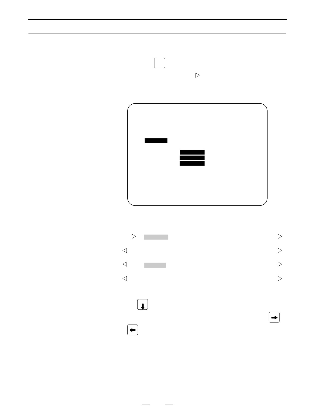
Screen Display
D Displaying the operation
(1) Press the
SYSTEM
function key.
history
(2) Press the continue menu key [
]. The [OPEHIS] [(OPRT)] soft key
are displayed.
(3) Press the [OPEHIS] soft key twice. The operation history screen is
displayed.
OPERATION HISTORY
O1234 N12345
Page : 123
No.DATA
No.DATA
No.DATA
01 92/06/03
11 F0000.7↑
21 F0001.0↓
02 08:40:00
12 F0000.5↑
22 <POS>
03 <DELETE>
13 F0001.0↑
23 <PROG>
04 F0000.6↑
14 F0000.5↓
24 <RESET>
05 MEM
15 P/S0010
25 EDIT
06 G0009.0↑
16 92/06/03
26 O
07 G0009.1↑
17 09:27:49
27 1
08 G0009.2↑
18 <PROG>
28 2
09 ST↑
19 <RESET>
29 3
10 ST↓
20 F0000.7↓
30 4
EDIT ****
***
***
08:20:52
[ TOP
][ BOTTOM ][
][
][PG.SRH]
On the operation history screen, the soft keys are configured as shown
below:
Í
[
] [ PARAM ] [DGNOS]
[PMC] [SYSTEM] [(OPE)]
[
]
ã push
[
]
[W.DGNS] [
]
[
] [OPEHIS]
[(OPE)]
[
]
ã push
[
]
[ OPEHIS ]
[SG-SEL]
[
] [
]
[(OPE)]
[
]
ã push
[
]
[ TOP
]
[BOTTOM][
] [
]
[PG.SRH] [
]
(4) To display the next part of the operation history, press the page down
key PAGE
. The next page is displayed.
To display the interface between two pages, press cursor key
or
. The screen is scrolled by one row. On a 14-inch CRT screen,
pressing the cursor key scrolls the screen by half a page.
These soft keys can also be used:
1 Pressing the [TOP] soft key displays the first page
(oldest data).
2 Pressing the [BOTTOM] soft key displays the last page
(latest data).
3 Pressing the [PG.SRH] soft key displays a specified page.
31
1. DISPLAY AND OPERATION OF CRT/MDI
B-62445E/03
Example) By entering 50 then pressing the [PG.SRH] key, page 50 is
displayed.
Data displayed on the operation history screen
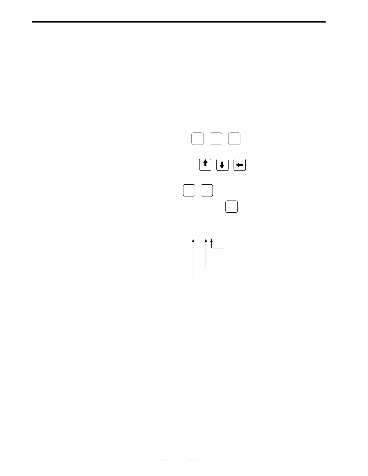
(1) MDI keys
Address and numeric keys are displayed after a single space.
Soft keys are displayed in square brackets ([]).
Other keys (RESET/INPUT, for example) are displayed in angle
brackets (<>).
A key pressed at power-on is displayed in reverse video.
For two-path control, the operations of path 2 are displayed in the
same way, but preceded by S_.
1
Function key:
POS
,
PROG
,
OFFSET
SETTING
, etc.
2
Address/numeric key: A to Z, 0 to 9, ; (EOB), +, -, (, etc.
3
Page/cursor key:
,
,
PAGE
4
Soft key: [SF1], [SF2], etc.
5
Other key:
RESET
,
CAN
, etc.
6
Key pressed at power-on:
RESET
(2) Input and output signals
General signals are displayed in the following format:
G 0 0 0 0 . 7 ↑
The ↑ mark indicates that the signal is
turned on.
The ↓ mark indicates that the signal is
turned off.
Indicates the bit.
Indicates the address.
Some signals are indicated by their symbol names.
SBK ↑ (Indicates that the single block switch is turned on.)
32
B-62445E/03
1. DISPLAY AND OPERATION OF CRT/MDI
Mode selection signals and rapid traverse override signals
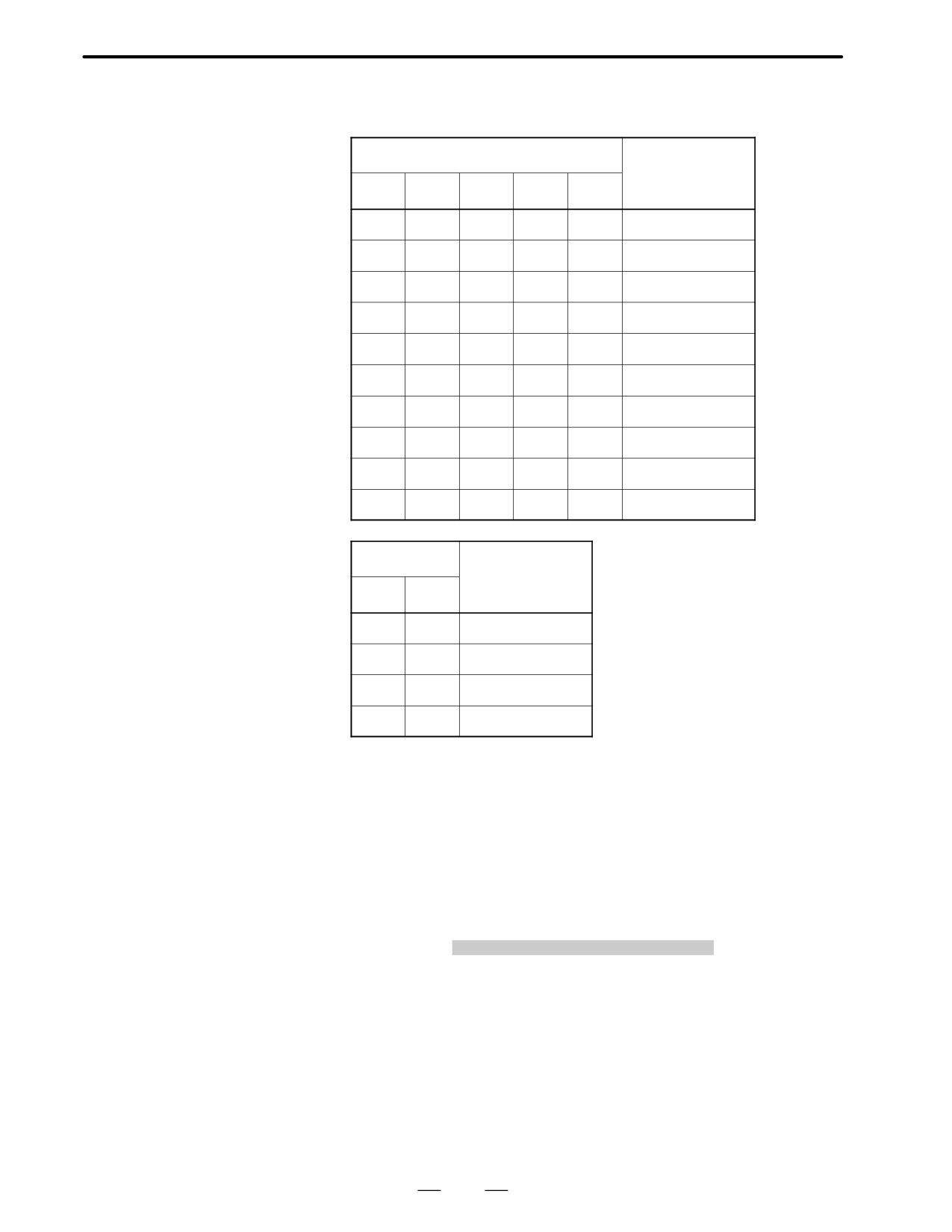
are displayed as indicated below:
Input signal
Name displayed
MD1
ND2
MD4
REF
DNC1
0
0
0
0
0
MDI
1
0
0
0
0
MEM
1
0
0
0
1
RMT
0
1
0
0
0
NOMODE
1
1
0
0
0
EDT
0
0
1
0
0
H/INC
1
0
1
0
0
JOG
1
0
1
1
0
REF
0
1
1
0
0
TJOG
1
1
1
0
0
THND
Input signal
Name displayed
RV1
RV2
0
0
R
100%
1
0
R
50%
0
1
R
25%
1
1
R F0%
(3) NC alarms
NC alarms are displayed in reverse video.
P/S alarms, system alarms, and external alarms are displayed together
with their numbers.
For other types of alarms, only the alarm type is displayed. (No details
are displayed.)
For two-path control, the operations of path 2 are displayed in the
same way, but preceded by S_.
Example) P/S0050, SV_ALM, S_APC_ALM
(4) Time stamp (date and time)
The following time data (date and time) is recorded:
1
Date and time of power-on
2
Date and time of power-off
3
Date and time when an NC alarm occurs
4
The clock time is recorded at predetermined intervals, together
with each new calendar day.
33
1. DISPLAY AND OPERATION OF CRT/MDI
B-62445E/03
1) The power-on time is displayed as shown below:
92/01/20 ==== Year/Month/Day
09:15:30 ==== Hour:Minute:Second
2) The power-off time and the time when an NC alarm occurred are
displayed in reverse video.
92/01/20
====
Year/Month/Day
09:15:30
====
Hour:Minute:Second
If a system alarm occurs, the date and time are not recorded.
3) At predetermined intervals, the clock time is displayed in reverse
video. Set the interval in minutes in parameter No. 3122. If zero
is set, the time is stamped at ten-minute intervals.
09:15:30
====
Hour:Minute:Second
Each new calendar day is displayed in reverse video.
92/01/20
====
Year/Month/Day
Note
The clock time is recorded for a specified interval only when
data is stored within that interval.
D Input signal or output
(1) P ress the
SYSTEM
function key.
signal to be recorded in
the operation history
(2) Press the continue menu key [
]. The [OPEHIS] (operation history)
soft key is displayed.
(3) Press the [OPEHIS] soft key, then press the [SG-SEL] soft key. The
operation history signal selection screen is displayed.
OP_HIS SIGNAL SELECT
O1000 N02000
No. ADDRES SIGNAL
No. ADDRES SIGNAL
01
X0000
00001000
11
G0000
00000001
02
X0004
10000000
12
G0004
00000011
03
X0008
00001100
13
G0008
00000111
04
X0009
00111000
14
G0003
00001111
05
X0012
00001111
15
G0043
01100000
06
Y0000
01000000
16
********
07
Y0004
00110000
17
********
08
Y0007
00011100
18
********
09
Y0008
00011100
19
********
10
Y0010
00011100
20
********
>
EDIT
**** *** * * *
00:00:00
[OPEHIS] [SG-SEL] [
] [
] [ (OPE) ]
34
B-62445E/03
1. DISPLAY AND OPERATION OF CRT/MDI
1.6.3
(1) On the operation history signal selection screen, press the [(OPE)] soft
Setting The Input
key.
Signal or Output Signal
to Be Recorded in The
OP_HIS SIGNAL SELECT
O1000 N02000
Operation History
No. ADDRES SIGNAL
No. ADDRES SIGNAL
01
G0004
00000010
11
********
02
********
12
********
03
********
13
********
04
********
14
********
05
********
15
********
06
********
16
********
07
********
17
********
08
********
18
********
09
********
19
********
10
********
20
********
>
EDIT **** *** *** *** 00:00:00
[ ALLDEL ][ DELETE ][ ON:1 ][ OFF:0 ][
]
(2) Press the cursor key
or
to position the cursor to a desired
position.
(3) Key in a signal type (X, G, F, or Y) and an address, then press the
INPUT
key.
Example) G0004
INPUT
Signal address G0004 is set in the ADDRES column. The
corresponding position in the SIGNAL column is initialized to
000000000.
(4) Select the bit to be recorded.
To select all bits of the specified signal address, press the [ON:1] soft
key while the cursor is positioned to 00000000 .
To select a particular bit, position the cursor to that bit by pressing the
cursor key
or
, then press the [ON:1] soft key. To cancel
a selection made by pressing the [ON:1] soft key or to cancel a
previously selected signal, press the [OFF:0] soft key.
(5) Up to 20 addresses can be specified by means of this signal selection.
These addresses need not always be specified at consecutive positions,
starting from No.1.
(6) Pressing the [ALLDEL] and [EXEC] soft keys deletes all data. If the
[ALLDEL] key is pressed by mistake, it can be cancelled by pressing
the [CAN] key.
(7) To delete a selected signal address, position the cursor to the
corresponding position then press the [DELETE] and [EXEC] soft
keys. In the SIGNAL column, asterisks ******** are displayed in
place of the deleted data. In the ADDRES column, the corresponding
position is cleared.
If the [DELET] key is pressed by mistake, it can be cancelled by
pressing the [CAN] key.
35
1. DISPLAY AND OPERATION OF CRT/MDI
B-62445E/03
(8) Pressing the return menu key [
] causes the [OPEHIS] (OPE) soft
key to be displayed again.
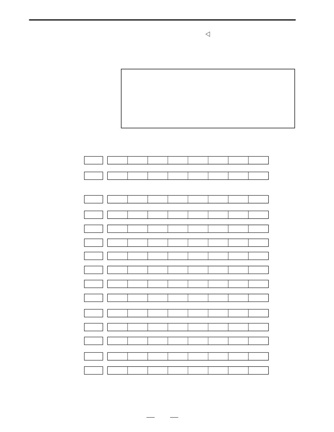
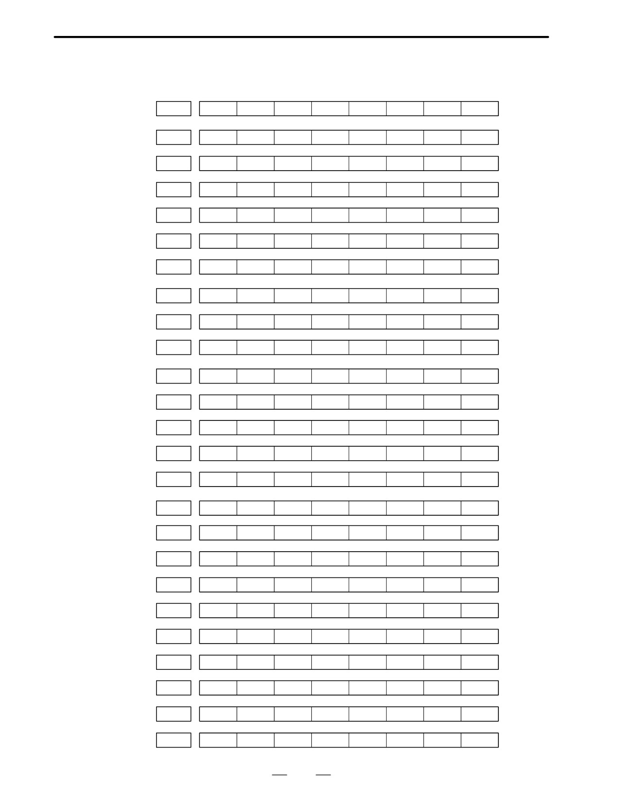
D Input signals and output
signals to be recorded in
the history
Notes
1
A cross (
) indicates that a signal will not be recorded.
Also, any signal for which an address is not specified will not
be recorded, either.
2
A circle (Ę) indicates that a signal can be recorded.
3
A signal indicated by its symbol name will also be displayed
by its symbol name.
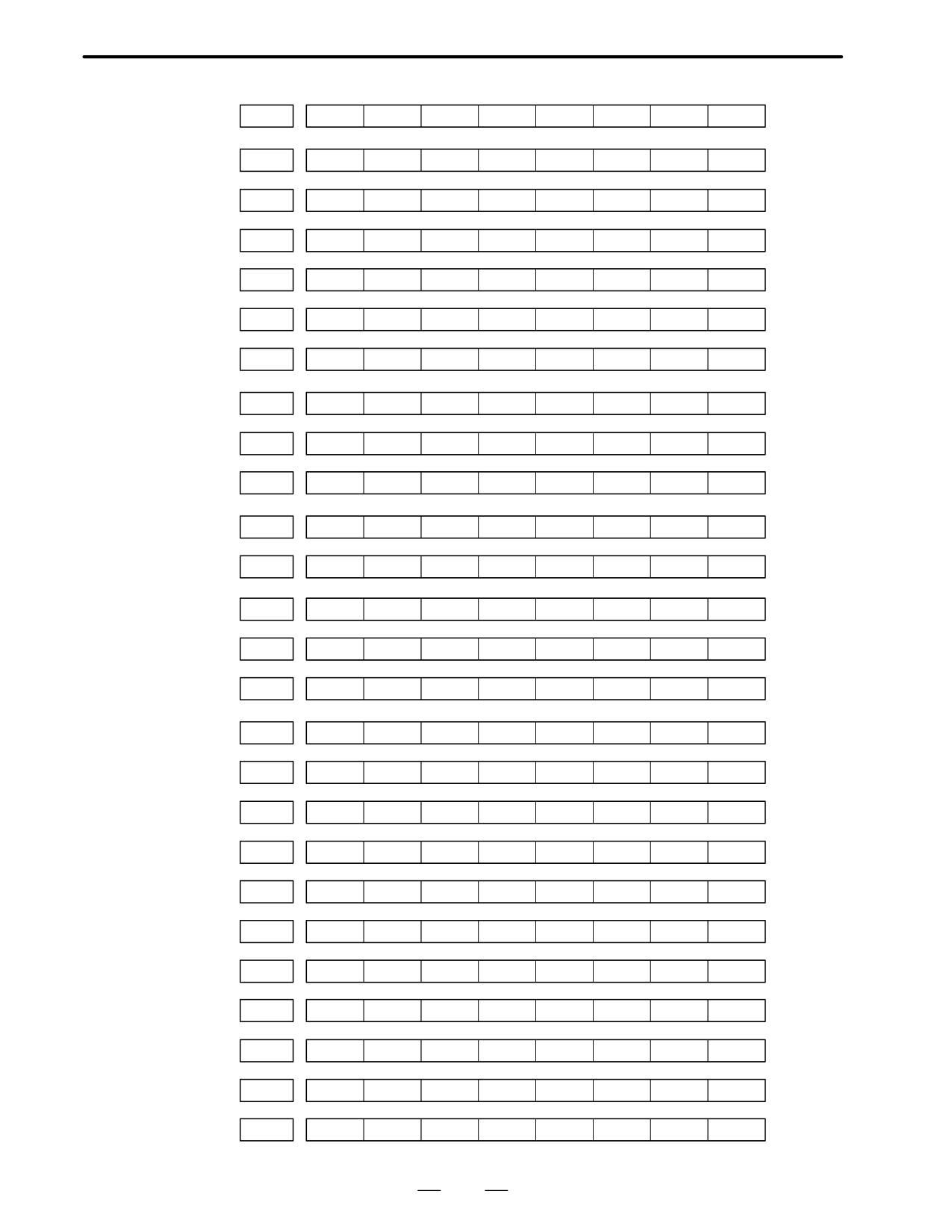
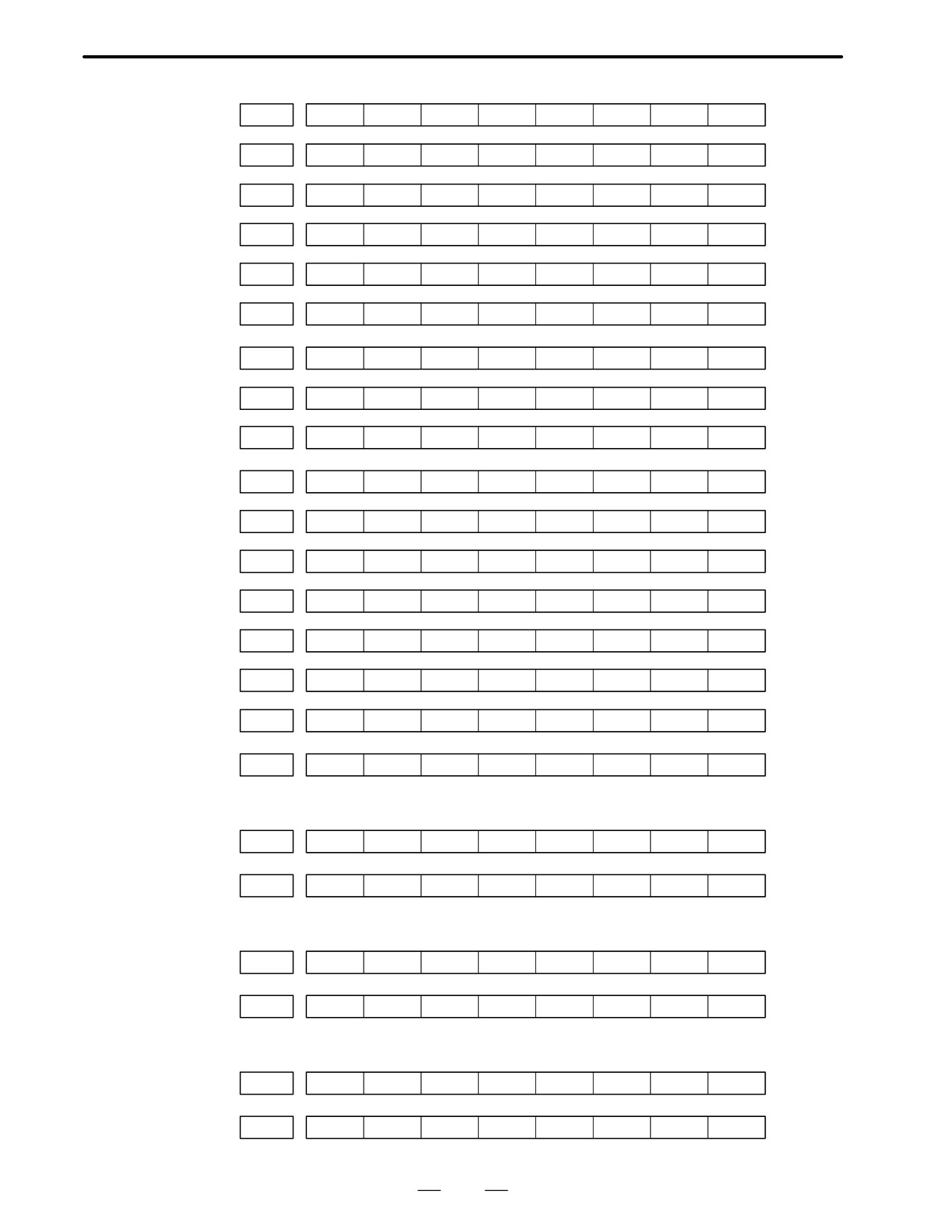
1. M/T addresses
MT→PMC
#7
#6
#5
#4
#3
#2
#1
#0
X000
f
f
f
f
f
f
f
f
:
X127
f
f
f
f
f
f
f
f
PMC→CNC
#7
#6
#5
#4
#3
#2
#1
#0
G000
f
f
f
f
f
f
f
f
:
G003
f
f
f
f
f
f
f
f
G004
f
f
f
f
FIN
f
f
f
G005
f
f
f
f
TFIN
SFIN
f
MFIN
G006
f
f
f
f
f
*ABS
f
SRN
G007
RLSOT
EXLM
*FLUP
f
f
ST
STLK
f
G008
ERS
RRW
*SP
*ESP
f
f
f
*IT
G009
f
f
f
f
f
f
f
f
:
G013
f
f
f
f
f
f
f
f
G014
f
f
f
f
f
f
f
f
G015
f
f
f
f
f
f
f
f
:
G018
f
f
f
f
f
f
f
f
G019
RT
f
f
f
f
f
f
f
36
B-62445E/03
1. DISPLAY AND OPERATION OF CRT/MDI
#7
#6
#5
#4
#3
#2
#1
#0
G020
f
f
f
f
f
f
f
f
:
G042
f
f
f
f
f
f
f
f
G043
f
×
f
×
×
f
f
f
G044
f
f
f
f
f
f
MLK
BDT1
G045
BDT9
BDT8
BDT7
BDT6
BDT5
BDT4
BDT3
BDT2
G046
DRN
KEY4
KEY3
KEY2
KEY1
f
SBK
f
G047
f
f
f
f
f
f
f
f
:
G060
f
f
f
f
f
f
f
f
G061
f
f
f
f
f
f
f
RGTA
G062
f
f
f
f
f
f
f
f
:
G099
f
f
f
f
f
f
f
f
G100
+J8
+J7
+J6
+J5
+J4
+J3
+J2
+J1
G101
f
f
f
f
f
f
f
f
G102
-J8
-J7
-J6
-J5
-J4
-J3
-J2
-J1
G103
f
f
f
f
f
f
f
f
:
G105
f
f
f
f
f
f
f
f
G106
MI8
MI7
MI6
MI5
MI4
MI3
MI2
MI1
G107
f
f
f
f
f
f
f
f
G108
MLK8
MLK7
MLK6
MLK5
MLK4
MLK3
MLK2
MLK1
G109
f
f
f
f
f
f
f
f
G110
+LM8
+LM7
+LM6
+LM5
+LM4
+LM3
+LM2
+LM1
G111
f
f
f
f
f
f
f
f
G112
-LM8
–LM7
-LM6
-LM5
-LM4
-LM3
-LM2
-LM1
G113
f
f
f
f
f
f
f
f
G114
*+L8
*+L7
*+L6
*+L5
*+L4
*+L3
*+L2
*+L1
37
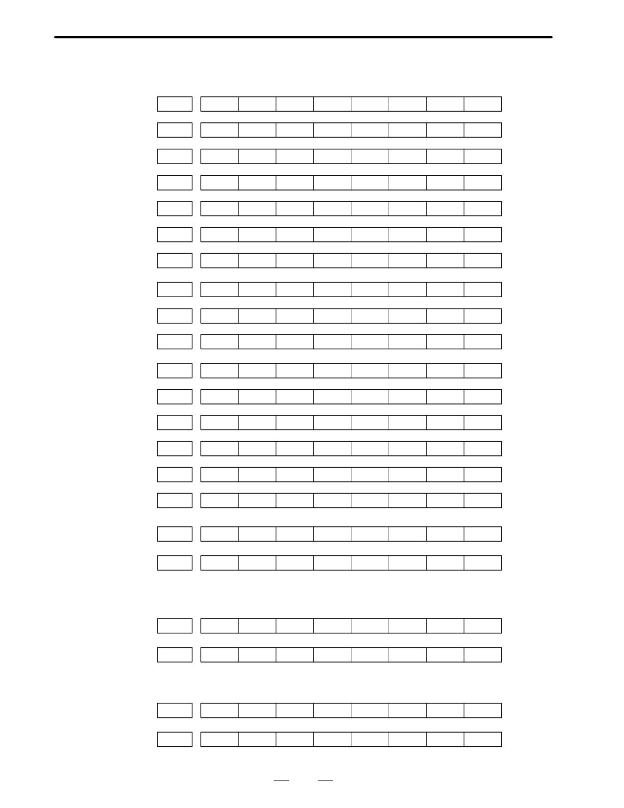
1. DISPLAY AND OPERATION OF CRT/MDI
B-62445E/03
#7
#6
#5
#4
#3
#2
#1
#0
G115
f
f
f
f
f
f
f
f
G116
*-L8
*-L7
*-L6
*-L5
*-L4
*-L3
*-L2
*-L1
G117
f
f
f
f
f
f
f
f
G118
*+ED8
*+ED7
*+ED6
*+ED5
*+ED4
*+ED3
*+ED2
*+ED1
G119
f
f
f
f
f
f
f
f
G120
*-ED8
*-ED7
*-ED6
*-ED5
*-ED4
*-ED3
*-ED2
*-ED1
G121
f
f
f
f
f
f
f
f
:
G125
f
f
f
f
f
f
f
f
G126
SVF8
SVF7
SVF6
SVF5
SVF4
SVF3
SVF2
SVF1
G127
f
f
f
f
f
f
f
f
:
G129
f
f
f
f
f
f
f
f
G130
*IT8
*IT7
*IT6
*IT5
*IT4
*IT3
*IT2
*IT1
G131
f
f
f
f
f
f
f
f
G132
f
f
f
f
+MIT4
+MIT3
+MIT2
+MIT1
G133
f
f
f
f
f
f
f
f
G134
f
f
f
f
-MIT4
-MIT3
-MIT2
-MIT1
G135
f
f
f
f
f
f
f
f
:
G255
f
f
f
f
f
f
f
f
PMC→MT
#7
#6
#5
#4
#3
#2
#1
#0
Y000
f
f
f
f
f
f
f
f
:
Y127
f
f
f
f
f
f
f
f
CNC→PMC
#7
#6
#5
#4
#3
#2
#1
#0
F000
f
f
f
f
f
f
f
f
:
F255
f
f
f
f
f
f
f
f
38
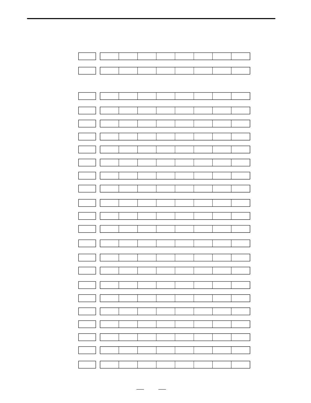
B-62445E/03
1. DISPLAY AND OPERATION OF CRT/MDI
2. List of Address for 2-path control
MT→PMC
#7
#6
#5
#4
#3
#2
#1
#0
X000
f
f
f
f
f
f
f
f
:
X127
f
f
f
f
f
f
f
f
PMC→CNC (Signals for tool post 1)
#7
#6
#5
#4
#3
#2
#1
#0
G000
f
f
f
f
f
f
f
f
:
G003
f
f
f
f
f
f
f
f
G004
f
f
f
f
FIN
f
f
f
G005
f
f
f
f
TFIN
SFIN
f
MFIN
G006
f
f
f
f
f
*ABS
f
SRN
G007
RLSOT
EXLM
*FLUP
f
f
ST
STLK
f
G008
ERS
RRW
*SP
*ESP
f
f
f
*IT
G009
f
f
f
f
f
f
f
f
:
G013
f
f
f
f
f
f
f
f
G014
f
f
f
f
f
f
f
f
G015
f
f
f
f
f
f
f
f
:
G018
f
f
f
f
f
f
f
f
G019
RT
f
f
f
f
f
f
f
G020
f
f
f
f
f
f
f
f
:
G042
f
f
f
f
f
f
f
f
G043
f
×
f
×
×
f
f
f
G044
f
f
f
f
f
f
MLK
BDT1
G045
BDT9
BDT8
BDT7
BDT6
BDT5
BDT4
BDT3
BDT2
G046
DRN
KEY4
KEY3
KEY2
KEY1
f
SBK
f
G047
f
f
f
f
f
f
f
f
:
G060
f
f
f
f
f
f
f
f
39
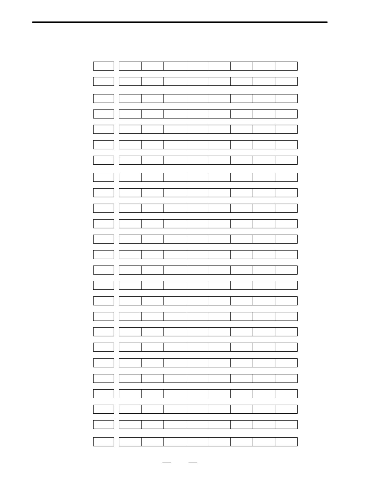
1. DISPLAY AND OPERATION OF CRT/MDI
B-62445E/03
#7
#6
#5
#4
#3
#2
#1
#0
G061
f
f
f
f
f
f
f
RGTA
G062
f
f
f
f
f
f
f
f
:
G099
f
f
f
f
f
f
f
f
G100
+J8
+J7
+J6
+J5
+J4
+J3
+J2
+J1
G101
f
f
f
f
f
f
f
f
G102
–J8
-J7
-J6
-J5
-J4
-J3
-J2
-J1
G103
f
f
f
f
f
f
f
f
:
G105
f
f
f
f
f
f
f
f
G106
MI8
MI7
MI6
MI5
MI4
MI3
MI2
SMI1
G107
f
f
f
f
f
f
f
f
G108
MLK8
MLK7
MLK6
MLK5
MLK4
MLK3
MLK2
MLK1
G109
f
f
f
f
f
f
f
f
G110
+LM8
+LM7
+LM6
+LM5
+LM4
+LM3
+LM2
+LM1
G111
f
f
f
f
f
f
f
f
G112
-LM8
–LM7
-LM6
-LM5
-LM4
-LM3
-LM2
-LM1
G113
f
f
f
f
f
f
f
f
G114
*+L8
*+L7
*+L6
*+L5
*+L4
*+L3
*+L2
*+L1
G115
f
f
f
f
f
f
f
f
G116
*-L8
*-L7
*-L6
*-L5
*-L4
*-L3
*-L2
*-L1
G117
f
f
f
f
f
f
f
f
G118
*+ED8
*+ED7
*+ED6
*+ED5
*+ED4
*+ED3
*+ED2
*+ED1
G119
f
f
f
f
f
f
f
f
G120
*-ED8
*-ED7
*-ED6
*-ED5
*-ED4
*-ED3
*-ED2
*-ED1
G121
f
f
f
f
f
f
f
f
:
G125
f
f
f
f
f
f
f
f
40
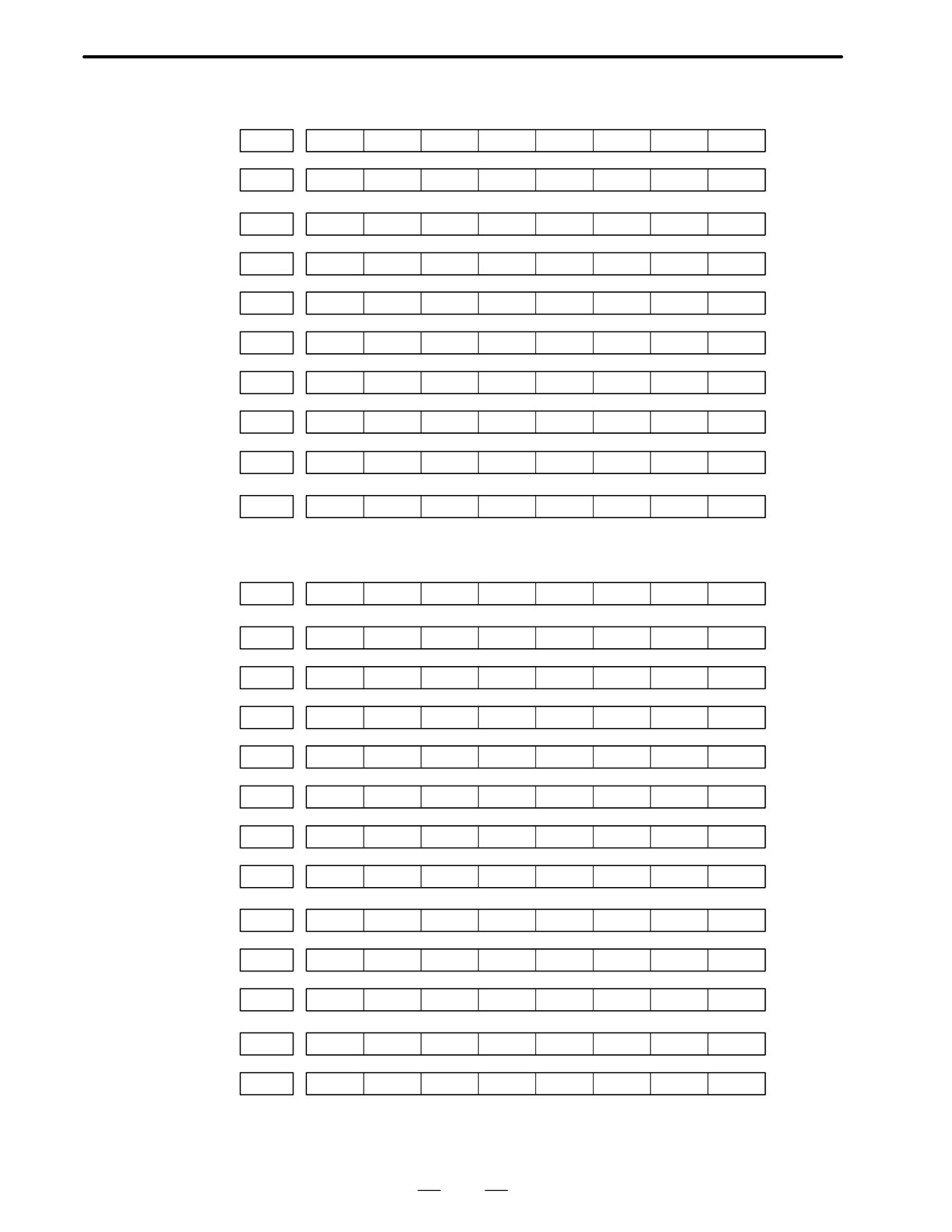
B-62445E/03
1. DISPLAY AND OPERATION OF CRT/MDI
#7
#6
#5
#4
#3
#2
#1
#0
G126
SVF8
SVF7
SVF6
SVF5
SVF4
SVF3
SVF2
SVF1
G127
f
f
f
f
f
f
f
f
:
G129
f
f
f
f
f
f
f
f
G130
*IT8
*IT7
*IT6
*IT5
*IT4
*IT3
*IT2
*IT1
G131
f
f
f
f
f
f
f
f
G132
f
f
f
f
+MIT4
+MIT3
+MIT2
+MIT1
G133
f
f
f
f
f
f
f
f
G134
f
f
f
f
-MIT4
-MIT3
-MIT2
-MIT1
G135
f
f
f
f
f
f
f
f
:
G255
f
f
f
f
f
f
f
f
PMC→CNC (Signals for the 2-path)
#7
#6
#5
#4
#3
#2
#1
#0
G1000
f
f
f
f
f
f
f
f
:
G1003
f
f
f
f
f
f
f
f
G1004
f
f
f
f
FIN
f
f
f
G1005
f
f
f
f
TFIN
SFIN
f
MFIN
G1006
f
f
f
f
f
*ABS
f
SRN
G1007
RLSOT
EXLM
*FLUP
f
f
ST
STLK
f
G1008
ERS
RRW
*SP
*ESP
f
f
f
*IT
G1009
f
f
f
f
f
f
f
f
:
G1013
f
f
f
f
f
f
f
f
G1014
f
f
f
f
f
f
f
f
G1015
f
f
f
f
f
f
f
f
:
G1018
f
f
f
f
f
f
f
f
G1019
RT
f
f
f
f
f
f
f
41
1. DISPLAY AND OPERATION OF CRT/MDI
B-62445E/03
#7
#6
#5
#4
#3
#2
#1
#0
G1020
f
f
f
f
f
f
f
f
:
G1042
f
f
f
f
f
f
f
f
G1043
f
×
f
×
×
f
f
f
G1044
f
f
f
f
f
f
MLK
BDT1
G1045
BDT9
BDT8
BDT7
BDT6
BDT5
BDT4
BDT3
BDT2
G1046
DRN
KEY4
KEY3
KEY2
KEY1
f
SBK
f
G1047
f
f
f
f
f
f
f
f
:
G1060
f
f
f
f
f
f
f
f
G1061
f
f
f
f
f
f
f
RGTA
G1062
f
f
f
f
f
f
f
f
:
G1099
f
f
f
f
f
f
f
f
G1100
+J8
+J7
+J6
+J5
+J4
+J3
+J2
+J1
G1101
f
f
f
f
f
f
f
f
G1102
-J8
–J7
-J6
-J5
-J4
-J3
-J2
-J1
G1103
f
f
f
f
f
f
f
f
:
G1105
f
f
f
f
f
f
f
f
G1106
MI8
MI7
MI6
MI5
MI4
MI3
MI2
SMI1
G1107
f
f
f
f
f
f
f
f
G1108
MLK8
MLK7
MLK6
MLK5
MLK4
MLK3
MLK2
MLK1
G1109
f
f
f
f
f
f
f
f
G1110
+LM8
+LM7
+LM6
+LM5
+LM4
+LM3
+LM2
+LM1
G1111
f
f
f
f
f
f
f
f
G1112
-LM8
–LM7
-LM6
-LM5
-LM4
-LM3
-LM2
-LM1
G1113
f
f
f
f
f
f
f
f
G1114
*+L8
*+L7
*+L6
*+L5
*+L4
*+L3
*+L2
*+L1
G1115
f
f
f
f
f
f
f
f
42
B-62445E/03
1. DISPLAY AND OPERATION OF CRT/MDI
#7
#6
#5
#4
#3
#2
#1
#0
G1116
*-L8
*-L7
*-L6
*-L5
*-L4
*-L3
*-L2
*-L1
G1117
f
f
f
f
f
f
f
f
G1118
*+ED8
*+ED7
*+ED6
*+ED5
*+ED4
*+ED3
*+ED2
*+ED1
G1119
f
f
f
f
f
f
f
f
G1120
*-ED8
*-ED7
*-ED6
*-ED5
*-ED4
*-ED3
*-ED2
*-ED1
G1121
f
f
f
f
f
f
f
f
:
G1125
f
f
f
f
f
f
f
f
G1126
SVF8
SVF7
SVF6
SVF5
SVF4
SVF3
SVF2
SVF1
G1127
f
f
f
f
f
f
f
f
:
G1129
f
f
f
f
f
f
f
f
G1130
*IT8
*IT7
*IT6
*IT5
*IT4
*IT3
*IT2
*IT1
G1131
f
f
f
f
f
f
f
f
G1132
f
f
f
f
+MIT4
+MIT3
+MIT2
+MIT1
G1133
f
f
f
f
f
f
f
f
G1134
f
f
f
f
-MIT4
-MIT3
-MIT2
-MIT1
G1135
f
f
f
f
f
f
f
f
:
G1255
f
f
f
f
f
f
f
f
PMC→MT
#7
#6
#5
#4
#3
#2
#1
#0
Y000
f
f
f
f
f
f
f
f
:
Y127
f
f
f
f
f
f
f
f
CNC→PMC (Signals for the 1-path)
#7
#6
#5
#4
#3
#2
#1
#0
F000
f
f
f
f
f
f
f
f
:
F255
f
f
f
f
f
f
f
f
CNC→PMC (Signals for the 2-path)
#7
#6
#5
#4
#3
#2
#1
#0
F1000
f
f
f
f
f
f
f
f
:
F1255
f
f
f
f
f
f
f
f
43

1. DISPLAY AND OPERATION OF CRT/MDI
B-62445E/03
1.6.4
Recorded data can be output to an input/output unit connected via a
reader/punch interface. An output record can be input from the
Inputting and
input/output unit.
outputting the
Set the input/output unit to be used in setting parameters No. 0020 and
operation history data
0100 to 0135.
To output the data, set a code in the ISO bit of a setting parameter (bit 1
of parameter No. 0020).
D Output
(1) Select EDIT mode.
(2) Press the
SYSTEM
key, then select the operation history display screen.
(3) Press the soft keys [(OPE)],
,
[PUNCH], and [EXEC] in this
order.
The data output to the FANUC Floppy Cassette or FANUC FA Card is
stored under file name OPERATION HISTORY.
D Input
(1) Select EDIT mode.
(2) Press the
SYSTEM
key, then select the operation history display screen.
(3) Press the soft keys [(OPE)],
,
[READ], and [EXEC] in this
order.
D Output data format
1. MDI/soft key
2. Signal
3. Alarm
4. For extension (date or time)
5. MDI/soft key of path 2
6. Signal of path 2
7. Alarm of path 2
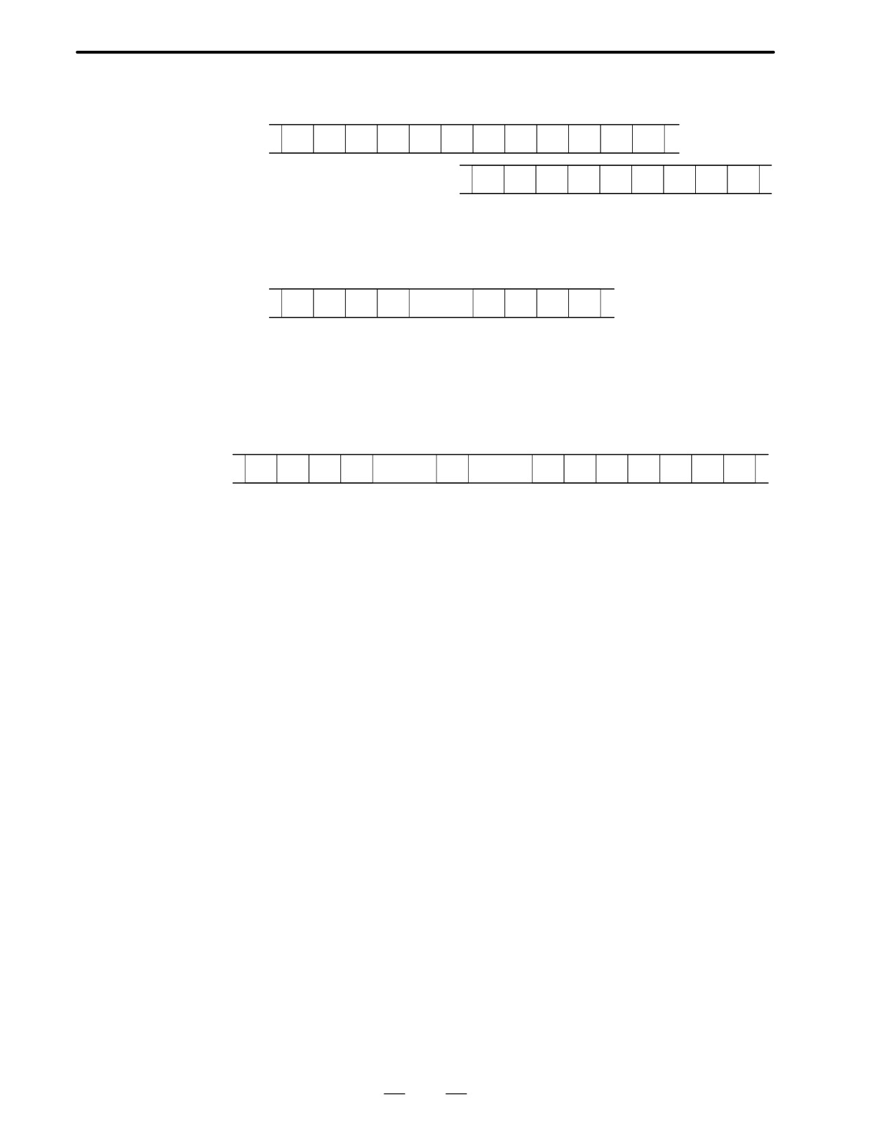
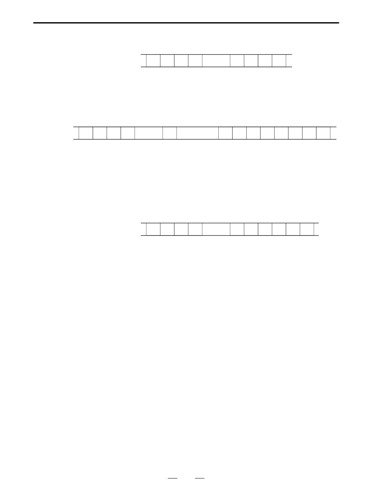
The header and recorded operation data are output, in this order. The
operation history data is divided into four parts by identifier words. Data
other than the identifier words depends on the type.
T(identifier word)
T0
: Header
T50
: MDI/soft key
T51
: Signal
T52
: Alarm
T53
: For extension (date or time)
T54
: MDI/soft key of path 2
T55
: Signal of path 2
T56
: Alarm of path 2
44
B-62445E/03
1. DISPLAY AND OPERATION OF CRT/MDI
1
Header
T
0
C
O
P
E
R
A
T
I
O
N
H
I
S
T
O
R
Y
;
C:
Data word
2
MDI/soft key
T
5
0
P
0 to 1
H
*
;
P0: Usually
P1: At power-on
H **: KCB code (See the following table.)
3
Signal
T
5
1
P
0 to 6
N
0 to 255
H
,
*
;
New data
Old data
P0: X0000 and above
P2: G0000 and above
P4: Y0000 and above
P6: F0000 and above
N***: DI/DO number
H **: Signal information data (hexadecimal)
45
1. DISPLAY AND OPERATION OF CRT/MDI
B-62445E/03
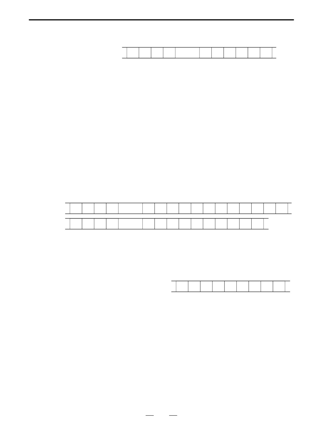
4
Alarm
T
5
2
P
0 to 10
N
*
;
P0: P/S No. 100
P1: P/S No. 000
P2: P/S No. 101
P3: P/S No. 0001 to 254
P4: Overtravel alarm
P5: Overheat alarm
P6: Servo alarm
P7: System alarm
P8: APC alarm
P9: Spindle alarm
P10: P/S alarm No. 5000 to 5999
P15: External alarm
N****: Alarm number (for P/S alarm, system alarm, and external
alarm only)
5
For extension (date or time)
Date
T
5
3
P
0 to 1
E
0
D
*
;
Time
T
5
3
P
0 to 1
E
1
D
*
*
*
*
*
;
P0: Usually
P1: At power-on
E0: Date
E1: Time
D*..*: Data Example) October 29, 1992
D
1
9
9
2
1
0
2
9
46
B-62445E/03
1. DISPLAY AND OPERATION OF CRT/MDI
6
MDI/soft key of path 2
T
5
4
P
0 to 1
H
;
P0: Usually
P1: At power-on
H **: KCB code (See the following table.)
7
Signal of path 2
T
5
5
P
2, 6
N
1000 to 1255
H
,
;
New data Old data
P2: G1000 and above
P6: F1000 and above
N***: DI/DO number
H **: Signal information data (hexadecimal)
8
Alarm of path 2
T
5
6
P
0 to 10
N
*
;
P0: P/S No. 100
P1: P/S No. 000
P2: P/S No. 101
P3: P/S No. 0001 to 254
P4: Overtravel alarm
P5: Overheat alarm
P6: Servo alarm
P7: System alarm
P8: APC alarm
P9: Spindle alarm
P10: P/S alarm No. 5000 to 5999
P15: External alarm
N****: Alarm number (for P/S alarm, system alarm, and external
alarm only)
47

1. DISPLAY AND OPERATION OF CRT/MDI
B-62445E/03
KCB codes (MDI/soft key)
(00H to 7FH)
0
1
2
3
4
5
6
7
0
Space
0
@
P
1
!
1
A
Q
2
”
2
B
R
3
#
3
C
S
4
$
4
D
T
5
%
5
E
U
6
&
6
F
V
7
’
7
G
W
8
(
8
H
X
9
)
9
I
Y
A
;
:
J
Z
(EOB)
B
+
K
[
C
’
<
L
o
D
-
=
M
]
E
>
N
F
/
?
O
-
48

B-62445E/03
1. DISPLAY AND OPERATION OF CRT/MDI
(80H to FFH)
8
9
A
B
C
D
E
F
0
Reset
F0
1
MMC
F1
2
CNC
F2
3
F3
4
Shift
Insert
F4
5
Delete
F5
6
CAN
Alter
F6
7
F7
8
Cur→
Input
Positn
F8
9
Cur←
Progrm
F9
A
Cur↓
Help
Offset
B
Cur↑
System
C
Messeg
D
Grp/Cs
*1*
E
Page↓
Custom
FR
F
Page↑
Fapt
FL
*
*1:On the small-sized keypad, ED corresponds to the Graph/Custom key.
On a standard keyboard, ED corresponds to the Graph key and EE to
the Custom key.
* : Command key
49
1. DISPLAY AND OPERATION OF CRT/MDI
B-62445E/03
1.6.5
Notes
(1) While the operation history screen is displayed, no information can be
recorded to the history.
(2) An input signal having an on/off width of up to 16 msec is not recorded
in the history. Some signals are not recorded in the history. See
Appendix 1.
(3) Once the storage becomes full, old data is deleted, starting from the
oldest record. Up to about 8000 key information items can be
recorded.
(4) The recorded data is retained even after the power is turned off. A
memory all clear operation, however, erases the recorded data.
(5) The operation history function cannot execute sampling when the
OHS bit (bit 7 of parameter No. 3106) is set to 1.
(6) Set the date and time on the setting screen.
(7) The time needed to input and output 6000 operation records at a rate
of 4800 baud is as follows:
Output:About 5 minutes
Input: About 2 minutes and 30 seconds
This file corresponds to a paper tape of about 180 m in length.
50
B-62445E/03
1. DISPLAY AND OPERATION OF CRT/MDI
1.7
HELP FUNCTION
1.7.1
General
The help function displays alarm information, operation method and a
table of contents for parameters. This function is used as a handbook.
1.7.2
Press HELP key on any screen other than PMC screen, then a help screen
appears.
Display Method
(However, it is not available when PMC screen is displaying)
D Display of help screen
HELP (INITIAL MENU)
O1234 N12345
*****
HELP
*****
1. ALARM DETAIL
2. OPERATION METHOD
3. PARAMETER TABLE
[1 ALAM]
[2 OPE]
[3 PARA]
[
]
[
]
D Help for alarm
1
When an alarm is generated, press soft key [1 ALAM], then a help
message of the alarm is displayed.
HELP (INITIAL MENU)
O1234 N12345
NUMBER
: 010
M’SAGE
: IMPROPER G CODE
FUNCTION
:
ALARM
:
A G CODE NOT LISTED IN G-CODE TABLE
IS BEING COMMANDED
ALSO G-CODE FOR FUNCTION NOT ADDED
IS BEING COMMANDED
[1 ALAM]
[2 OPE]
[3 PARA] [
] [ OPRT ]
2
Pressing soft key [OPRT],(alarm No.), and soft key [SELECT] in
this order, a help message corresponding to the input alarm number is
displayed.
51