FANUC Series 16 / 160 / 18 / 180 – Model B. Maintenance Manual - page 1
GE Fanuc Automation
Computer Numerical Control Products
Series 16 / 160 / 18 / 180 - Model B
Maintenance Manual
GFZ-62445E/03
January 1995
B-62445E/03
PREFACE
PREFACE
Description of
1.CRT/MDI display and operation
this manual
This chapter covers those items, displayed on the CRT, that are related to
maintenance. A list of all supported operations is also provided at the end
of this chapter.
2.Hardware
This chapter covers hardware-related items, including the hardware
configuration, connection, and NC status indicated on printed circuit
boards. A list of all units is also provided as well as an explanation of how
to replace each unit.
3.Data input/output
This chapter describes the input/output of data, including programs,
parameters, and tool compensation data, aswell as the input/output
procedures for conversational data.
4.Interface between the NC and PMC
This chapter describes the PMC specifications, the system configuration,
and the signals used by the PMC.
5.Digital servo
This chapter describes the servo tuning screen and how to adjust the
reference position return position.
6.and 7. AC spindles
These chapters describe the spindle amplifier checkpoints, as well as the
spindle tuning screen.
8.Trouble shooting
This chapter describes the procedures to be followed in the event of
certain problems occurring, for example, if the power cannot be turned on
or if manual operation cannot be performed. Countermeasures to be
applied in the event of alarms being output are also described.
9.and 10. Spindle trouble shooting
These chapters explain the alarms related to spindles, as well as the
corresponding countermeasures to be applied.
APPENDIX
The appendix consists of a list of all alarms, as well as a list of
maintenance parts. The I/O Unit-MODEL A is also described.
This manual does not provide a parameter list. If necessary, refer to the
separate PARAMETER DESCRIPTIONS (B-61810E) .
This manual describes all optional functions. Refer to the manual
provided by the machine tool builder for details of any options with which
the installed machine tool is provided.
PREFACE
B-62445E/03
This manual can be used with the following models. The abbreviated
names may be used.
Applicable models
Pruduct name
Abbreviation
FANUC Series 16-TB
16-TB
T series or
T series (two–path
FANUC Series 160-TB
160-TB
control)*1
FANUC Series 16-MB
16-MB
M series or M se-
ries (two–path
FANUC Series 160-MB
160-MB
control)*1
FANUC Series 18-TB
18-TB
T series or
T series (two–path
FANUC Series 180-TB
180-TB
control)*1
FANUC Series 18-MB
18-MB
M series
FANUC Series 180-MB
180-MB
Note
Some function described in this manual may not be applied
to some products.
For details, refer to the DESCRIPTIONS manual
(B-62442E)
Related manuals
The table below lists manuals related to MODEL B of Series 16, Series
18, Series 160 and Series 180.
In the table, this manual is marked with an asterisk(*).
Table 1 Manuals Related
Manual name
Specification
number
DESCRIPTIONS
B-62442E
CONNECTION MANUAL (HARDWARE)
B-62443E
CONNECTION MANUAL (FUNCTION)
B-62443E-1
OPERATOR’S MANUAL FOR LATHE
B-62444E
OPERATOR’S MANUAL FOR MACHINING
B-62454E
MAINTENANCE MANUAL
B-62445E
*
PARAMETER MANUAL
B-62450E
PROGRAMMING MANUAL (Macro Compiler / Macro Execu-
B-61803E-1
ter)
FAPT MACRO COMPILER PROGRAMMING MANUAL
B-66102E
FANUC Super CAP T OPERATOR’S MANUAL
B-62444E-1
FANUC Super CAP M OPERATOR’S MANUAL
B-62154E
FANUC Super CAP M PROGRAMMING MANUAL
B-62153E
B-62445E/03
PREFACE
Table 1 Manuals Related
Manual name
Specification
number
CONVERSATIONAL AUTOMATIC PROGRAMMING FUNC-
B-61804E-1
TION I FOR LATHE (Series 18-TB) OPERATOR’S MANUAL
CONVERSATIONAL AUTOMATIC PROGRAMMING FUNC-
B-61804E-2
TION II FOR LATHE (Series 15-MODEL B, Series-16 CAP II)
OPERATOR’S MANUAL
For specifications and maintenance of FANUC CONTROL MOTOR α
series, refer to the following manuals :
Document
Document name
Major contents
Major usage
number
D Specification
FANUC AC SERVO MOTOR α series
D Characteristics
B-65142E
DESCRIPTIONS
D External dimensions
D Connections
D Selection of motor
D Specification
D Connection of motor
FANUC AC SPINDLE MOTOR α series
D Characteristics
B-65152E
DESCRIPTIONS
D External dimensions
D Connections
D Specifications and
functions
D Selection of
FANUC CONTROL MOTOR AMPLIFIER
D Installation
amplifier
B-65162E
α series DESCRIPTIONS
D External dimensions and
D Connection of
maintenance area
amplifier
D Connections
D Start up the system
D Start up procedure
(Hardware)
FANUC CONTROL MOTOR α series
B-65165E
D Troubleshooting
D Troubleshooting
MAINTENANCE MANUAL
D Maintenance of motor
D Maintenance of
motor
D Initial setting
FANUC AC SERVO MOTOR α series
B-65150E
D Setting parameters
PARAMETER MANUAL
D Start up the system
D Description of parameters
(Software)
D Initial setting
D Turning the system
FANUC AC SPINDLE MOTOR α series
(Parameters)
B-65160E
D Setting parameters
PARAMETER MANUAL
D Description of parameters
B-62445E/03
Table of Contents
1. DISPLAY AND OPERATION OF CRT/MDI .
1
1.1
FUNCTION KEYS AND SOFT KEYS
2
1.1.1
Soft Keys
2
1.2
SCREEN DISPLAYED IMMEDIATELY AFTER POWER IS TURNED ON
22
1.2.1
Slot Status Display
22
1.2.2
Setting Module Screen
23
1.2.3
Configuration Display of Software
23
1.3
SYSTEM CONFIGURATION SCREEN
24
1.3.1
Display Method
24
1.3.2
Configuration of PCBs
24
1.3.3
Software Configuration Screen
26
1.3.4
Module Configuration Screen
26
1.4
ALARM HISTORY SCREEN
27
1.4.1
General
27
1.4.2
Screen Display
27
1.4.3
Clearing Alarm History
27
1.4.4
Alarm Display
27
1.5
EXTERNAL OPERATOR MESSAGES RECORD
28
1.5.1
Screen Display
28
1.5.2
Deletion of External Operator Messages Record
28
1.5.3
Parameter
29
1.5.4
Notes
29
1.6
OPERATION HISTORY
30
1.6.1
Parameter Setting
30
1.6.2
Screen Display
31
1.6.3
Setting the Input Signal or Output Signal to be Recorded in the Operation History
35
1.6.4
Inputting and Outputting the Operation History Data
44
1.6.5
Notes
50
1.7
HELP FUNCTION
51
1.7.1
General
51
1.7.2
Display Method
51
1.8
DISPLAYING DIAGNOSTIC PAGE
54
1.8.1
Displaying Diagnostic Page
54
1.8.2
Contents Displayed
54
1.9
NC STATE DISPLAY
68
1.10
WAVE FORM DIAGNOSTIC FUNCTION
69
1.10.1
Setting Parameters
69
1.10.2
Waveform Diagnostic Parameter Screen
70
1.10.3
Graphic of Wave Diagnosis Data
73
1.10.4
Data Sampling for Storage Type Waveform Diagnosis
75
1.10.5
Outputting Waveform Diagnosis Data (Storage Type)
77
1.11
OPERATING MONITOR
80
1.11.1
Display Method
80
1.12
LIST OF OPERATIONS
82
1.13
WARNING SCREEN DISPLAYED WHEN AN OPTION IS CHANGED
86
1.14
WARNING SCREEN DISPLAYED WHEN SYSTEM SOFTWARE IS REPLACED
(SYSTEM LABEL CHECK ERROR)
88
2. HARDWARE .
89
2.1
STRUCTURE
90
c-1
TABLE OF CONTENTS
B–62445E/03
2.2
GENERAL OF HARDWARE
91
2.2.1
Series 16
91
2.3
TOTAL CONNECTION DIAGRAM
92
2.3.1
16-TB/MB, 160-TB/MB (MAIN-A SPEC.)
93
2.3.2
16-TB/MB, 160-TB/MB, 18-TB/MB, 180-TB/MB (MAIN-B SPEC.)
95
2.3.3
18-TB/MB
97
2.4
INTER-MACHINE CONNECTION
99
2.4.1
CRT/MDI Unit
99
2.4.2
Reader/Puncher Interface
101
2.4.3
Manual Pulse Generator
102
2.4.4
I/O LINK
103
2.4.5
Servo Interface
105
2.4.6
Connections by Type of Detectors
109
2.4.7
Combining Serial Spindle and Analog Spindle
112
2.4.8
Connection to α serial Spindle Amplifier
113
2.4.9
Connection to Serial Spindle Amplifier
114
2.4.10
Connection to Analog Spindle Amplifier
115
2.4.11
Remote Buffer Interface
115
2.4.12
High-speed DI Signal Interface
117
2.4.13
Analog Signal Interface
119
2.4.14
Environmental Requirement
120
2.4.15
Power Capacity
120
2.4.16
Action Against Noise
120
2.5
LED DISPLAY AND MODULE CONFIGURATION OF PCB
126
2.5.1
Power Supply Unit
126
2.5.2
Main CPU Board
130
2.5.3
Option 1 Board
140
2.5.4
Option 2 Board
142
2.5.5
Option 3 Board
148
2.5.6
Loader Control Boad
151
2.5.7
I/O Card (Sink Type Output)
154
2.5.8
I/O Card (Source Type Output)
154
2.5.9
I/O Cards with Power Supply (Power C) (Sink Type Output)
155
2.5.10
I/O Cards with Power Supply (Power C) (Source Type Output)
157
2.5.11
Background Graphic Board
159
2.6
LIST OF THE PCBS AND UNITS
161
2.6.1
Control Unit Rack
161
2.6.2
Power Unit
162
2.6.3
Control Unit P.C.B
162
2.6.4
Modules
164
2.6.5
CRT/MDI Unit
166
2.7
HOW TO REPLACE THE MODULES
172
2.7.1
Removing
172
2.7.2
Insertion
172
2.8
HOW TO REPLACE THE BATTERIES
173
2.8.1
Replace the Battery for Memory Back Up
173
2.8.2
Replacing Batteries for Separate Absolute Pulse Coder
174
2.9
HOW TO REPLACE FAN MOTOR
175
2.10
FUSE REPLACEMENT IN POWER SUPPLY UNIT
176
2.11
MAINTENANCE OF HEAT PIPE TYPE HEAT EXCHANGER
177
c-2
B-62445E/03
TABLE OF CONTENTS
2.12
HOW TO REPLACE THE COLOR LIQUID CRYSTAL DISPLAY
180
2.13
REPLACING THE LCD FUSE
181
2.14
REPLACING THE LCD BAKLIGHT
182
3. INPUT AND OUTPUT OF DATA .
183
3.1
SETTING PARAMETERS FOR INPUT/OUTPUT
184
3.2
INPUTTING/ OUTPUTTING DATA
186
3.2.1
Confirming the Parameters Required for Data Output
186
3.2.2
Outputting CNC Parameters
187
3.2.3
Outputting PMC Parameters
188
3.2.4
Outputting Pitch Error Compensation Amount
188
3.2.5
Outputting Custom Macro Variable Values
189
3.2.6
Outputting Tool Compensation Amount
189
3.2.7
Outputting Part Program
190
3.2.8
Inputting CNC Parameters
190
3.2.9
Inputting PMC Parameters
192
3.2.10
Inputting Pitch Error Compensation Amount
192
3.2.11
Inputting Custom Macro Variable Values
193
3.2.12
Inputting Tool Compensation Amount
193
3.2.13
Inputting Part Programs
194
3.3
INPUT/OUTPUT SUPER CAP DATA
195
3.3.1
Input/Output of Conversational Data in a Lump(Super CAP M)
195
3.3.2
Input and Output of Each File
197
3.3.3
Output of CAP Data (Super CAP T)
197
3.3.4
Inputting CAP Data (Super CAP T)
202
3.4
INPUTTING/OUTPUTT ING CAP-II DATA(16-T)
205
3.5
DUMP/RESTORE OF CAP-II DATA (16 - T)
207
3.5.1
Kind of Data in Sub Memory
207
3.5.2
Operation
207
3.6
CLEARING CAP-II DATA (16 - T)
208
3.6.1
Deleting File Name and Files
208
3.6.2
Clearing CAP-II Memory
209
4. INTERFACE BETWEEN NC AND PMC .
210
4.1
GENERAL OF INTERFACE
211
4.2
SPECIFICATION OF PMC
212
4.2.1
Specification
212
4.2.2
Address
213
4.2.3
Built-in Debug Function
214
4.2.4
System Reserve Area of Internal Relay
214
4.2.5
Execution Period of PMC
217
4.3
PMC SCREEN
218
4.3.1
Display Method
218
4.3.2
PMCLAD Screen
219
4.3.3
PMCDGN Screen
223
4.3.4
Memory Display (M.SRCH)
227
4.3.5
PMCRAM Screen
231
4.4
LIST OF SIGNALS BY EACH MODE
237
4.5
SIGNAL AND SYMBOL CORRESPONDENCE TABLE
239
c-3
TABLE OF CONTENTS
B–62445E/03
5. DIGITAL SERVO .
247
5.1
INITIAL SETTING SERVO PARAMETERS
248
5.2
SERVO TUNING SCREEN
253
5.2.1
Parameter Setting
253
5.2.2
Displaying Servo Tuning Screen
253
5.3
ADJUSTING REFERENCE POSITION (DOG METHOD)
256
5.3.1
General
256
5.4
DOGLESS REFERENCE POSITION SETTING
258
5.4.1
General
258
5.4.2
Operation
258
5.4.3
Associated Parameters
259
6. AC SPINDLE (SERIAL INTERFACE) .
260
6.1
GENERAL OF SPINDLE CONTROL (SERIAL* INTERFACE)
261
6.1.1
Method A of Gear Change for Machining Center
262
6.1.2
Method B of Gear Change for Machining Center(PRM 3705#2=1)
262
6.1.3
For Lathe
262
6.2
TABLE OF TEST POINTS
263
6.2.1
Printed Circuit Board (A16B-2201-0440)
263
6.2.2
Signal Waveform At Test Points
265
6.3
CONFIRMING POWER SUPPLY (SERIAL INTERFACE)
266
6.3.1
Power Supply
266
6.3.2
Test Points
266
6.4
SPINDLE SETTING AND TUNING SCREEN
269
6.4.1
Display Method
269
6.4.2
Spindle Setting Screen
269
6.4.3
Spindle Tuning Screen
270
6.4.4
Spindle Monitor Screen
272
6.4.5
Correspondence Between Operation Mode and Parameters on Spindle Tuning Screen
274
6.5
AUTOMATIC SETTING OF STANDARD PARAMETER
277
7. AC SPINDLE (ANALOG INTERFACE) .
278
7.1
GENERAL OF SPINDLE CONTROL (ANALOG INTERFACE)
279
7.1.1
Block Diagram
279
7.1.2
Calculation of S Analog Voltage and Associated Parameters
280
7.1.3
Tuning S Analog Voltage (D/A Converter)
282
7.2
TABLE OF TEST POINTS
284
7.2.1
Model 1S to 3S (Amp. Specification : A06B-6059-H00x)
284
7.2.2
Models 6S to 26S (Amp. specification: A06B-6059-H2xx)
285
7.2.3
Test Points Signal Waveform
286
7.3
SETTING PARAMETERS (DIGITAL AC SPINDLE)
287
7.4
SETTING STANDARD PARAMETERS
288
7.5
LIST OF PARAMETER
289
7.6
TUNING AFTER REPLACING PCB (S SERIES AC SPINDLE)
292
8. TROUBLESHOOTING .
294
8.1
CORRECTIVE ACTION FOR FAILURES
296
8.1.1
Investigating the Conditions under which Failure Occurred
296
c-4
B-62445E/03
TABLE OF CONTENTS
8.2
POWER CANNOT BE TURNED ON
298
8.3
NO MANUAL OPERATION NOR AUTOMATIC OPERATION CAN BE EXECUTED
301
8.4
JOG OPERATION CANNOT BE DONE
305
8.5
HANDLE OPERATION CANNOT BE DONE
309
8.6
AUTOMATIC OPERATION CANNOT BE DONE
312
8.7
CYCLE START LED SIGNAL HAS TURNED OFF
321
8.8
NOTHING IS DISPLAYED ON CRT
323
8.9
ALARM 85 TO 87 (READER/PUNCHER INTERFACE ALARM)
326
8.10
REFERENCE POSITION DEVIATES
335
8.11
ALARM 90 (REFERENCE POSITION RETURN IS ABNORMAL)
336
8.12
ALARM 300 (REQUEST FOR REFERENCE POSITION RETURN)
338
8.13
ALARM 301 TO 305 (ABSOLUTE PULSE CODER IS FAULTY)
339
8.14
ALARM 306 TO 308 (ABSOLUTE PULSE CODER BATTERY IS LOW)
342
8.15
ALARM 350 (SERIAL PULSE CODER IS ABNORMAL)
343
8.16
ALARM 351 (SERIAL PULSE CODER COMMUNICATION IS ABNORMAL)
344
8.17
ALARM 400 (OVERLOAD)
345
8.18
ALARM 401 (*DRDY SIGNAL TURNED OFF)
347
8.19
ALARM 404 AND 405 (*DRDY SIGNAL TURNED ON)
349
8.20
ALARM 410 (EXCESSIVE POSITION ERROR AMOUNT DURING STOP)
350
8.21
ALRAM 411 (EXECESSIVE POSITION ERROR DURING MOVE)
351
8.22
ALARM 414 (DIGITAL SERVO SYSTEM IS ABNORMAL)
353
8.23
ALRAM 416 (DISCONNECTION ALARM)
365
8.24
ALARM 417 (DIGITAL SERVO SYSTEM IS ABNORMAL)
366
8.25
ALARM 700 (OVERHEAT AT CONTROL SIDE)
367
8.26
ALARM 704 (SPINDLE SPEED FLUCTUATION DETECTION ALARM)
368
8.27
ALARM 749 (SERIAL SPINDLE COMMUNICATION ERROR)
369
8.28
ALARM 750 (SPINDLE SERIAL LINK CANNOT BE STARTED)
372
8.29
ALARM 751,761 (SPINDLE ALARM)
377
8.30
ALARM 900 (ROM PARITY ERROR)
378
8.31
ALARM 910 TO 915 (SRAM PARITY)
381
8.32
ALARM 916 (DRAM PARITY ERROR)
384
8.33
ALARM 920 TO 923 (WATCH DOG OR RAM PARITY)
386
8.34
ALARM 924 (SERVO MODULE MOUNTING ERROR)
390
8.35
ALARM 930 (CPU ERROR)
391
8.36
ALARM 950 (PMC SYSTEM ALARM)
392
8.37
ALARM
951 (PMC-RCWATCH DOG ALARM)
394
8.38
ALARM 970 (NMI ALARM IN PMC CONTROL MODULE)
395
8.39
ALARM 971 (NMI ALARM IN SLC)
397
8.40
ALARM 972 (NMI ALARM)
398
8.41
ALARM 973 (NMI ALARM BY UNKNOWN CAUSE)
399
9. TROUBLESHOOTING (SERIAL INTERFACE SPINDLE) .
400
9.1
LIST OF SERIAL INTERFACE SPINDLE AMPLIFIER ALARMS
401
9.2
TROUBLESHOOTING FOR EACH ALARM
404
10. TROUBLESHOOTING (ANALOG INTERFACE SPINDLE) .
411
10.1
AL-01 (MOTOR OVERHEAT)
412
c-5
TABLE OF CONTENTS
B–62445E/03
10.2
AL-02 (EXCESSIVE DEVIATION OF SPEED)
413
10.3
AL-06, 07 (OVER SPEED)
414
10.4
AL-09 (UNIT OVERHEAT / 6S TO 26S ONLY)
415
10.5
AL-10 (LOW INPUT VOLTAGE)
416
10.6
AL-11 (DC LINK EXCESSIVE VOLTAGE)
417
10.7
AL-12 (DC LINK EXCESSIVE CURRENT)
418
10.8
ABNORMAL SOUND AND VIBRATION DURING ROTATION
419
10.9
NO ROTATION OR INCORRECT SPEED
420
10.10
CONFIRMATION OF TRANSISTOR MODULE
421
APPENDIXES
A. I/O UNIT MODEL A .
425
A.1
SYSTEM CONFIGURATION
426
A.2
HARDWARE CONFIGURATION
426
A.3
LED INDICATION
427
A.4
FUSES
428
A.5
REMOVING A PRINTED CIRCUIT BOARD
429
B. ALARM LIST .
431
B.1
LIST OF ALARM CODES
432
B.2
LIST OF ALARMS (PMC)
456
B.3
SPINDLE ALARMS (SERIAL SPINDLE)
463
B.4
SPINDLE ALARMS (ANALOG INTERFACE) (S SEIRES AC SPINDLE)
468
C. LIST OF MAINTENANCE PARTS .
471
C.1
MAINTENANCE PARTS
472
D. BOOT SYSTEM .
487
D.1
OVERVIEW
488
D.1.1
Starting the Boot System
488
D.1.2
System Files and User Files
489
D.1.3
Boot Slot Configuration Screen
489
D.2
SCREEN CONFIGURATION AND OPERATING PROCEDURE
490
D.2.1
System Data Loading Screen
491
D.2.2
System Data Check Screen
493
D.2.3
System Data Delete Screen
495
D.2.4
System Data Save Screen
496
D.2.5
SRAM Data Backup Screen
498
D.2.6
Memory Card File Delete Screen
501
D.2.7
Memory Card Format Function
502
D.2.8
Load Basic System Function
503
D.3
ERROR MESSAGES AND REQUIRED ACTIONS
504
E. NOTATION OF MDI KEYS .
506
c-6
B-62445E/03
1. DISPLAY AND OPERATION OF CRT/MDI
DISPLAY AND OPERATION OF CRT/MDI
1
This chapter describes how to display various screens by the function
keys. The screens used for maintenance are respectively displayed.
1.1
FUNCTION KEYS AND SOFT KEYS .
2
1.2
SCREEN DISPLAYED IMMEDIATELY AFTER
POWER IS TURNED ON .
22
1.3
SYSTEM CONFIGURATION SCREEN .
24
1.4
ALARM HISTORY SCREEN .
27
1.5
EXTERNAL OPERATOR MESSAGES
RECORD .
28
1.6
OPERATION HISTORY .
30
1.7
HELP FUNCTION .
51
1.8
DISPLAYING DIAGNOSTIC PAGE .
54
1.9
NC STATE DISPLAY .
68
1.10
WAVE FORM DIAGNOSTIC FUNCTION .
69
1.11
OPERATING MONITOR .
80
1.12
LIST OF OPERATIONS .
82
1.13
WARNING SCREEN DISPLAYED WHEN
AN OPTION IS CHANGED .
86
1.14
WARNING SCREEN DISPLAYED
WHEN SYSTEM SOFTWARE IS REPLACED
(SYSTEM LABEL CHECK ERROR) .
88
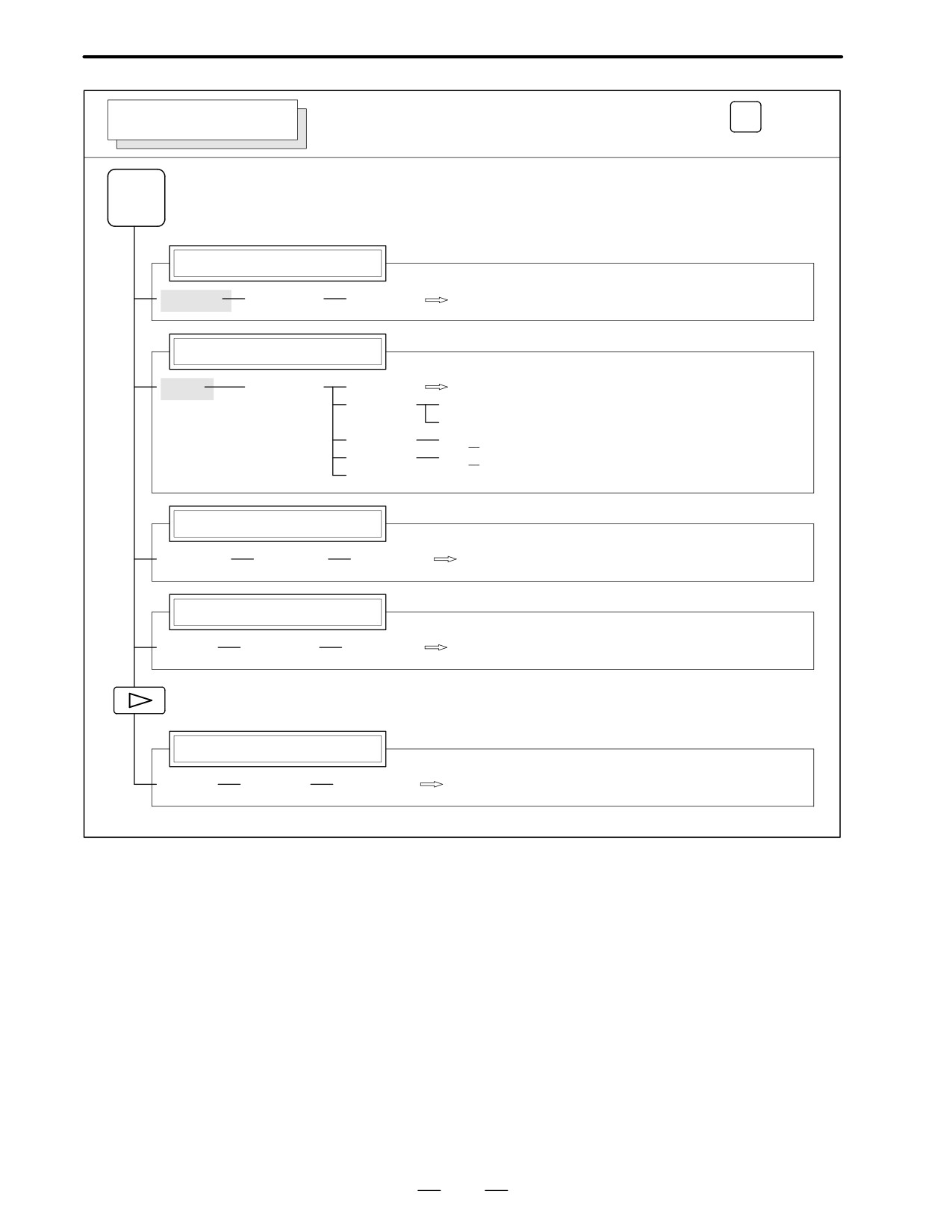
1
1. DISPLAY AND OPERATION OF CRT/MDI
B-62445E/03
Operations and soft key display staturs for each function key are described
1.1
below:
FUNCTION KEYS
AND SOFT KEYS
1.1.1
To display a more detailed screen, press a function key followed by a soft
key. Soft keys are also used for actual operations.
Soft Keys
The following illustrates how soft key displays are changed by pressing
each function key.
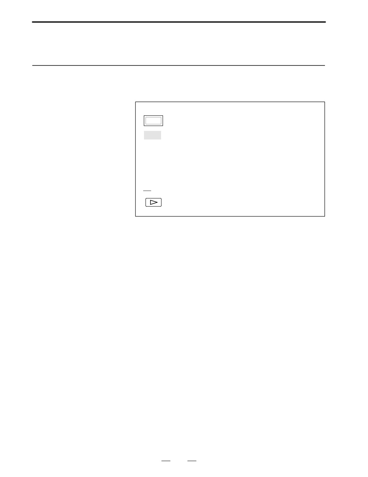
The symbols in the following figures mean as shown below :
:
Indicates screens
:
Indicates a screen that can be displayed by pressing a
function key(*1)
[
]
:
Indicates a soft key(*2)
(
)
:
Indicates input from the MDI panel.
[
]
:
Indicates a soft key displayed in green (or highlighted).
:
Indicates the continuous menu key (rightmost soft key)(*3).
*1 Press function keys to switch between screens that are used frequently.
*2 Some soft keys are not displayed depending on the option configuration.
*3 In some cases, the continuous menu key is omitted when the 14″ CRT
display or 8.4″/9.5″/LCD is used.
2
B-62445E/03
1. DISPLAY AND OPERATION OF CRT/MDI
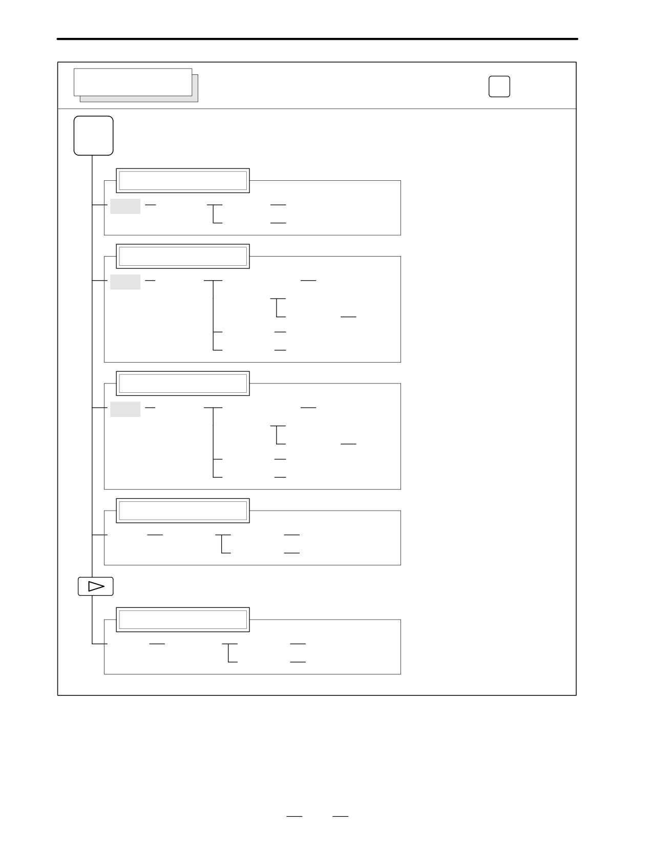
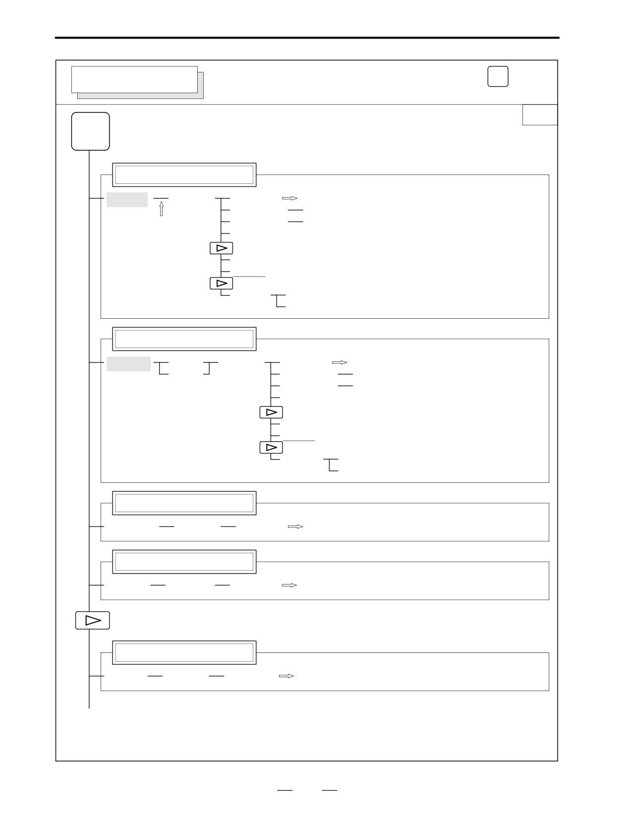
POSITION SCREEN
Soft key transition triggered by the function key
POS
POS
Absolute coordinate display
[ABS]
[(OPRT)]
[PTSPRE]
[EXEC]
[RUNPRE]
[EXEC]
Relative coordinate display
[REL]
[(OPRT)]
(Axis or numeral)
[PRESET]
[ORIGIN]
[ALLEXE]
[Axis name]
[EXEC]
[PTSPRE]
[EXEC]
[RUNPRE]
[EXEC]
Current position display
[ALL]
[(OPRT)]
(Axis or numeral)
[PRESET]
[ORIGIN]
[ALLEXE]
[Axis name]
[EXEC]
[PTSPRE]
[EXEC]
[RUNPRE]
[EXEC]
Handle interruption
[HNDL]
[(OPRT)]
[PTSPRE]
[EXEC]
[RUNPRE]
[EXEC]
Monitor screen
[MONI]
[(OPRT)]
[PTSPRE]
[EXEC]
[RUNPRE]
[EXEC]
3
1. DISPLAY AND OPERATION OF CRT/MDI
B-62445E/03
Soft key transition triggered by the function key
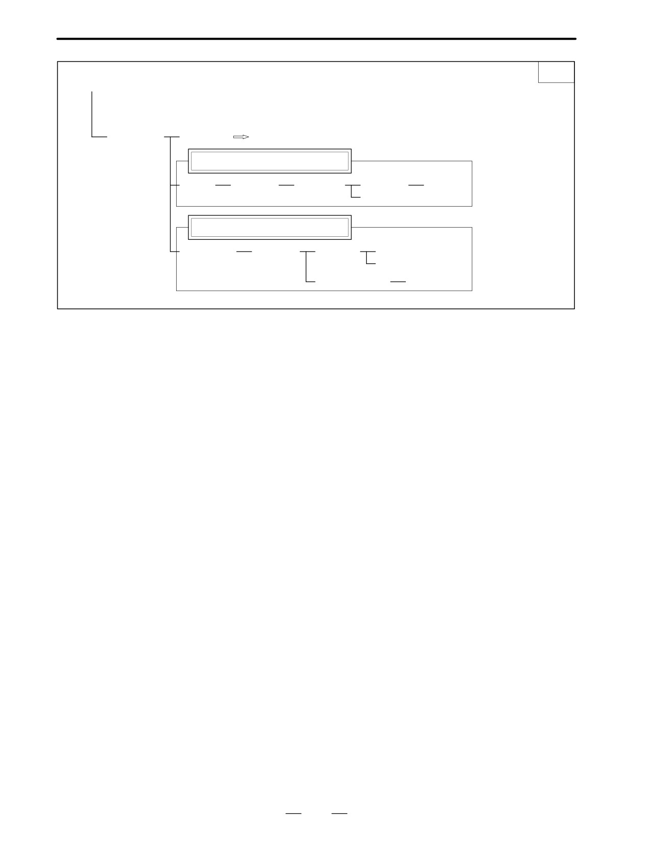
PROG
PROGRAM SCREEN
in the MEM mode
1/2
PROG
Program display screen
[PRGRM]
[(OPRT)]
[BG-EDT]
See"When the soft key [BG-EDT] is pressed"
[O number]
[O SRH]
[N number]
[N SRH]
(1)
[REWIND]
[P TYPE]
[Q TYPE]
[F SRH]
[CAN]
[EXEC]
Program check display screen
[CHECK]
[ABS]
[(OPRT)]
[BG-EDT]
See"When the soft key [BG-EDT] is pressed"
[REL]
[O number]
[O SRH]
[N number]
[N SRH]
[REWIND]
[P TYPE]
[Q TYPE]
[F SRH]
[CAN]
[EXEC]
Current block display screen
[CURRNT]
[(OPRT)]
[BG-EDT]
See"When the soft key [BG-EDT] is pressed"
Next block display screen
[NEXT]
[(OPRT)]
[BG-EDT]
See"When the soft key [BG-EDT] is pressed"
Program restart display screen
[RSTR]
[(OPRT)]
[BG-EDT]
See"When the soft key [BG-EDT] is pressed"
(2)(Continued on the next page)
4
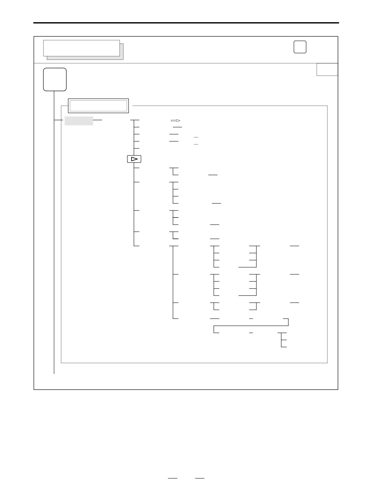
B-62445E/03
1. DISPLAY AND OPERATION OF CRT/MDI
2/2
(2)
[FL.SDL]
[PRGRM]
Return to (1) (Program display)
File directory display screen
[DIR]
[(OPRT)]
[SELECT]
[File No. ]
[F SET]
[EXEC]
Schedule operation display screen
[SCHDUL]
[(OPRT)]
[CLEAR]
[CAN]
[EXEC]
(Schedule data)
[INPUT]
5
1. DISPLAY AND OPERATION OF CRT/MDI
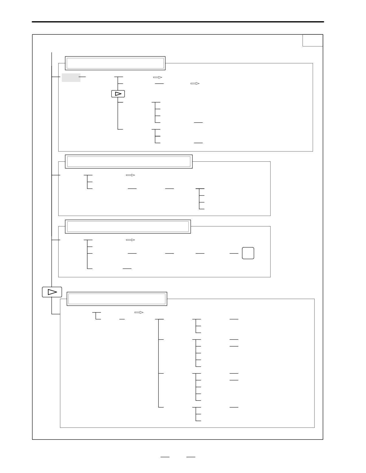
B-62445E/03
Soft key transition triggered by the function key
PROG
PROGRAM SCREEN
in the EDIT mode
1/2
PROG
Program display
[PRGRM]
[(OPRT)]
[BG-EDT]
See"When the soft key [BG-EDT] is pressed"
(O number)
[O SRH]
(Address)
[SRH↓]
(Address)
[SRH↑]
[REWIND]
[F SRH]
[CAN]
(N number)
[EXEC]
[READ]
[CHAIN]
(The cursor moves to the end of a program.)
[STOP]
[CAN]
(O number)
[EXEC]
[PUNCH]
[STOP]
[CAN]
(O number)
[EXEC]
[DELETE]
[CAN]
(N number)
[EXEC]
[EX-EDT]
[COPY]
[CRSR - ]
(O number)
[EXEC]
[ - CRSR]
[ - BTTM]
[ALL]
[MOVE]
[CRSR∼]
(O number)
[EXEC]
[ - CRSR]
[ - BTTM]
[ALL]
[MERGE]
[ - CRSR]
(O number)
[EXEC]
[ - BTTM]
[CHANGE]
(Address)
[BEFORE]
(Address)
[AFTER]
[SKIP]
[1-EXEC]
[EXEC]
(1)(Continued on the next page)
6
B-62445E/03
1. DISPLAY AND OPERATION OF CRT/MDI
2/2
(1)
Program directory display
[LIB]
[(OPRT)]
[BG-EDT]
See"When the soft key [BG-EDT] is pressed"
(O number)
[O SRH]
Return to the program
[READ]
[CHAIN]
[STOP]
[CAN]
(O number)
[EXEC]
[PUNCH]
[STOP]
[CAN]
(O number)
[EXEC]
Graphic Conversational Programming (T series)
[C.A.P.]
[PRGRM]
Return to the program
[G.MENU]
(G number)
[BLOCK]
(Data)
[LINE]
When a G number is omitted,
[CHAMF]
the standard screen appears.
[CNR.R]
[INPUT]
Graphic Conversational Programming (M series)
[C.A.P.]
[PRGRM]
Return to the program
[G.MENU]
(G number)
[BLOCK]
(Data)
[INPUT]
INSERT
When a G number is omitted, the standard screen appears.
[(OPRT)]
[INPUT]
Floppy directory display
[FLOPPY]
[PRGRM]
Return to the program
[DIR]
[(OPRT)]
[F SRH]
(Numeral)
[F SET]
[CAN]
[EXEC]
[READ]
(Numeral)
[F SET]
(Numeral)
[O SET]
[STOP]
[CAN]
[EXEC]
[PUNCH]
(Numeral)
[F SET]
(Numeral)
[O SET]
[STOP]
[CAN]
[EXEC]
[DELETE]
(Numeral)
[F SET]
[CAN]
[EXEC]
7
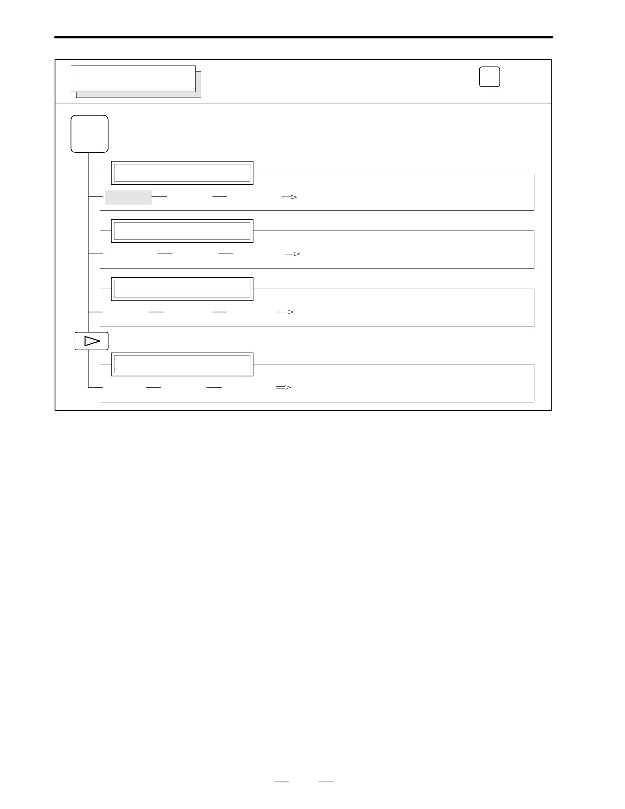
1. DISPLAY AND OPERATION OF CRT/MDI
B-62445E/03
Soft key transition triggered by the function key
PROG
PROGRAM SCREEN
in the MDI mode
PROG
Program display
[PRGRM]
[(OPRT)]
[BG-EDT]
See"When the soft key [BG-EDT] is pressed"
Program input screen
[MDI]
[(OPRT)]
[BG-EDT]
See"When the soft key [BG-EDT] is pressed"
[START]
[CAN]
[EXEC]
(Address)
[SRH↓]
(Address)
[SRH↑]
[REWIND]
Current block display screen
[CURRNT]
[(OPRT)]
[BG-EDT]
See"When the soft key [BG-EDT] is pressed"
Next block display screen
[NEXT]
[(OPRT)]
[BG-EDT]
See"When the soft key [BG-EDT] is pressed"
Program restart display screen
[RSTR]
[(OPRT)]
[BG-EDT]
See"When the soft key [BG-EDT] is pressed"
8
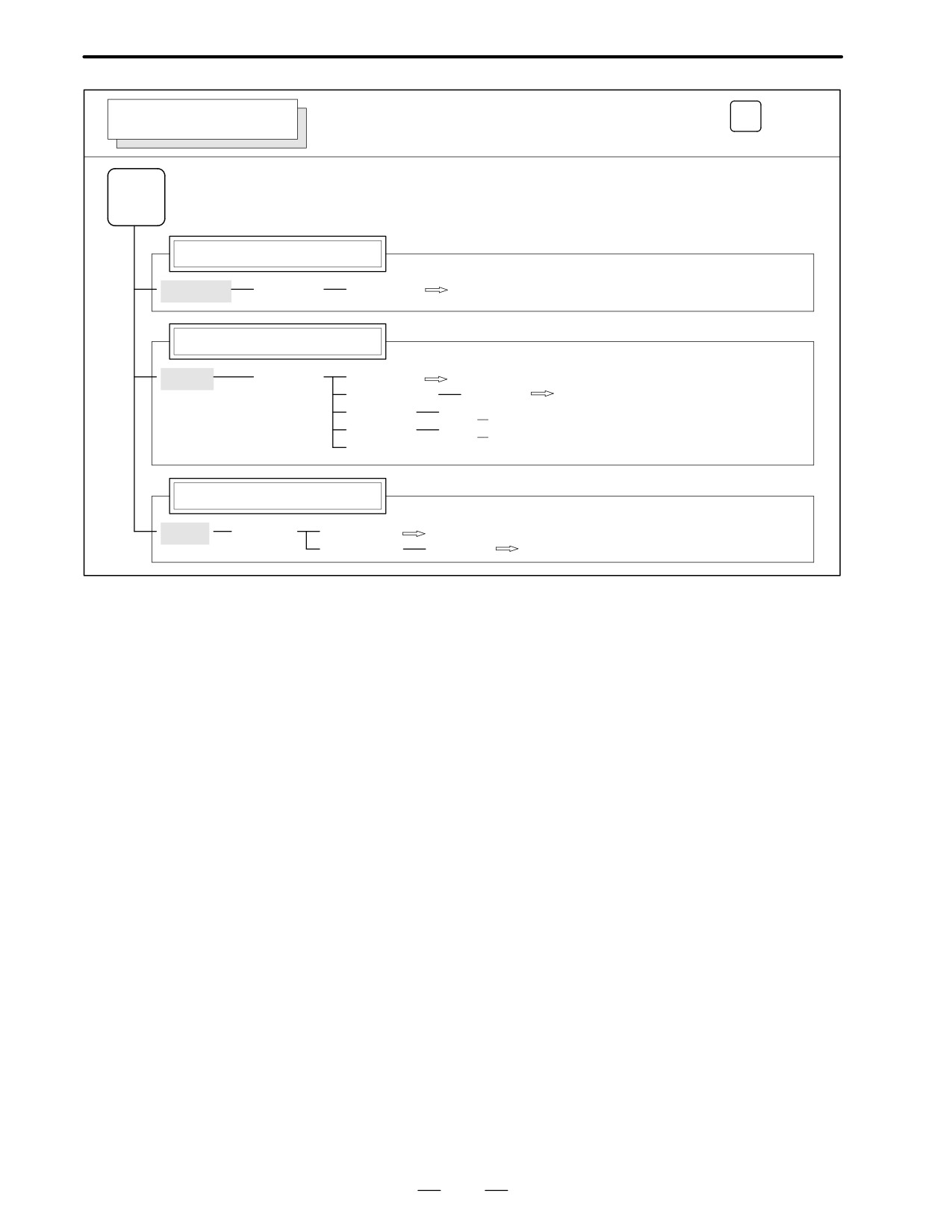
B-62445E/03
1. DISPLAY AND OPERATION OF CRT/MDI
Soft key transition triggered by the function key
PROG
PROGRAM SCREEN
in the HNDL, JOG, or REF mode
PROG
Program display
[PRGRM]
[(OPRT)]
[BG-EDT]
See"When the soft key [BG-EDT] is pressed"
Current block display screen
[CURRNT]
[(OPRT)]
[BG-EDT]
See"When the soft key [BG-EDT] is pressed"
Next block display screen
[NEXT]
[(OPRT)]
[BG-EDT]
See "When the soft key [BG-EDT] is pressed"
Program restart display screen
[RSTR]
[(OPRT)]
[BG-EDT]
See"When the soft key [BG-EDT] is pressed"
9
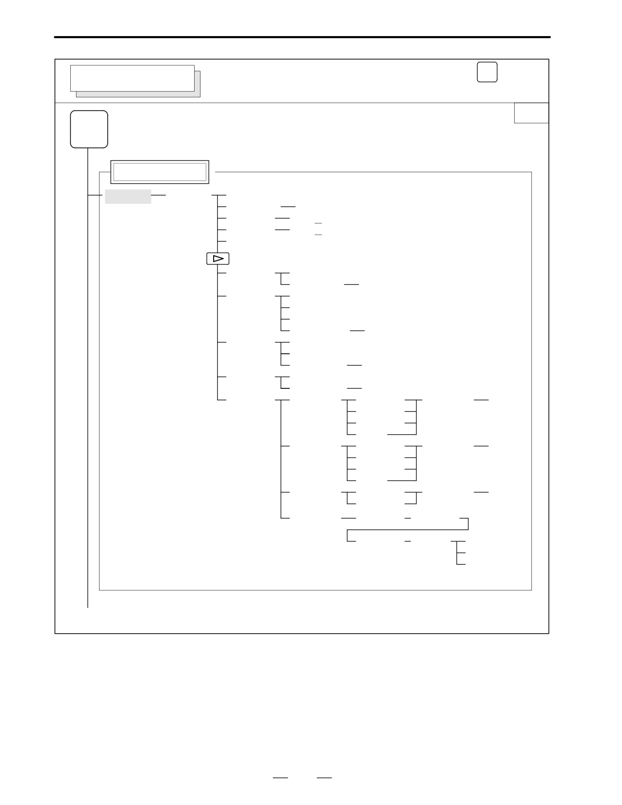
1. DISPLAY AND OPERATION OF CRT/MDI
B-62445E/03
Soft key transition triggered by the function key
PROG
PROGRAM SCREEN
in the TJOG or THDL mode
PROG
Program display
[PRGRM]
[(OPRT)]
[BG-EDT]
See "When the soft key [BG-EDT] is pressed"
Program input screen
[MDI]
[(OPRT)]
[BG-EDT]
See "When the soft key [BG-EDT] is pressed"
(O number)
[O SRH]
Return to the program
(Address)
[SRH↓]
(Address)
[SRH↑]
[REWIND]
Program directory display
[LIB]
[(OPRT)]
[BG-EDT]
See "When the soft key [BG-EDT] is pressed"
(O number)
[O SRH]
Return to the program
10
B-62445E/03
1. DISPLAY AND OPERATION OF CRT/MDI
PROG
Soft key transition triggered by the function key
PROGRAM SCREEN
(When the soft key [BG-EDT] is pressed in all modes)
1/2
PROG
Program display
[PRGRM]
[(OPRT)]
[BG-END]
(O number)
[O SRH]
(Address)
[SRH↓]
(Address)
[SRH↑]
[REWIND]
[F SRH]
[CAN]
(N number)
[EXEC]
[READ]
[CHAIN]
(The cursor moves to the end of a program.)
[STOP]
[CAN]
(O number)
[EXEC]
[PUNCH]
[STOP]
[CAN]
(O number)
[EXEC]
[DELETE]
[CAN]
(N number)
[EXEC]
[EX-EDT]
[COPY]
[CRSR - ]
(O number)
[EXEC]
[ - CRSR]
[ - BTTM]
[ALL]
[MOVE]
[CRSR - ]
(O number)
[EXEC]
[ - CRSR]
[ - BTTM]
[ALL]
[MERGE]
[ - CRSR]
(O number)
[EXEC]
[ - BTTM]
[CHANGE]
(Address)
[BEFORE]
(Address)
[AFTER]
[SKIP]
[1-EXEC]
[EXEC]
(1)(Continued on the next page)
11
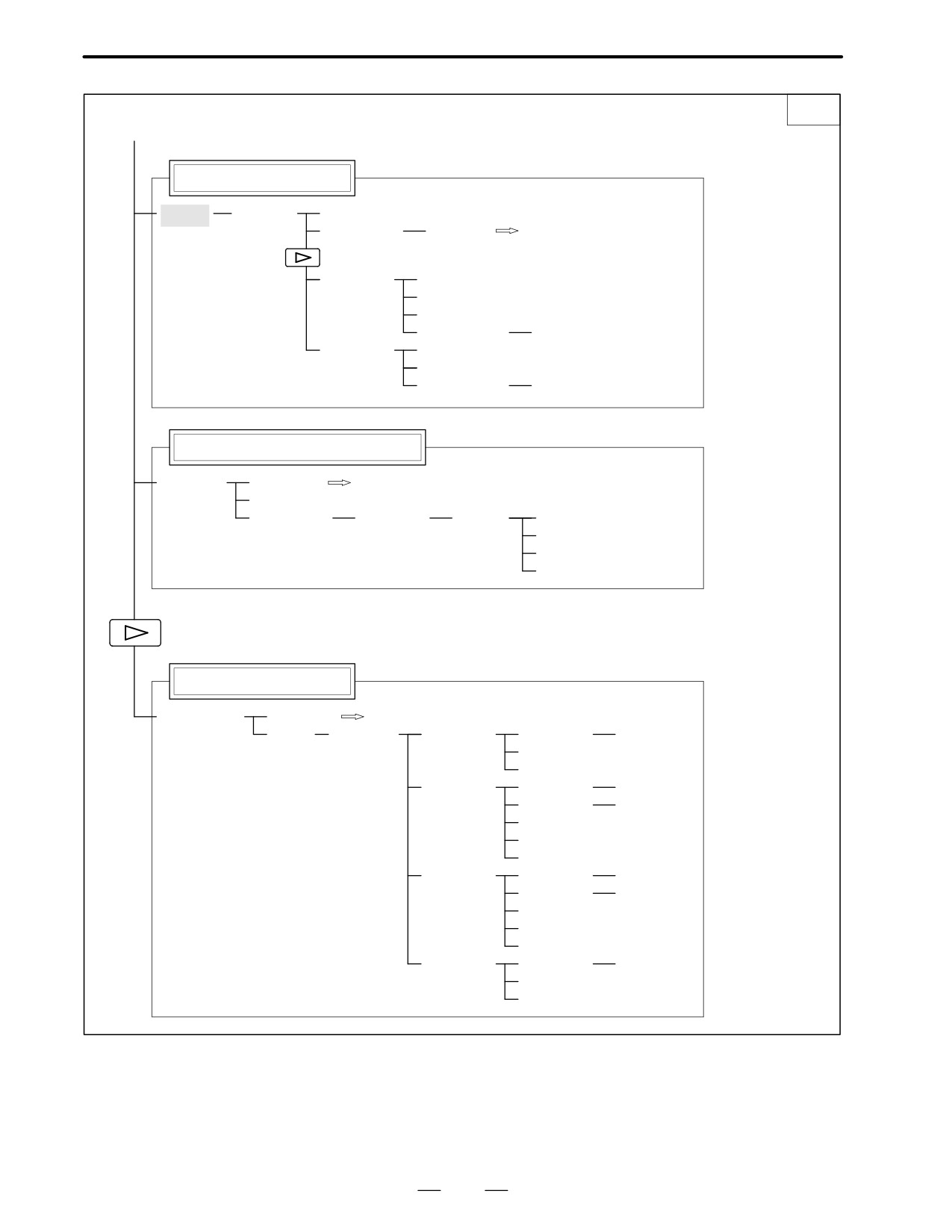
1. DISPLAY AND OPERATION OF CRT/MDI
B-62445E/03
2/2
(1)
Program directory display
[LIB]
[(OPRT)]
[BG-EDT]
(O number)
[O SRH]
Return to the program
[READ]
[CHAIN]
[STOP]
[CAN]
(O number)
[EXEC]
[PUNCH]
[STOP]
[CAN]
(O number)
[EXEC]
Graphic Conversational Programming
[C.A.P.]
[PRGRM]
Return to the program
[G.MENU]
(G number)
[BLOCK]
(Data)
[LINE]
[CHAMF]
When a G number is omitted, the standard
screen appears.
[CNR.R]
[INPUT]
Floppy directory display
[FLOPPY]
[PRGRM]
Return to the program
[DIR]
[(OPRT)]
[F SRH]
(Numeral)
[F SET]
[CAN]
[EXEC]
[READ]
(Numeral)
[F SET]
(Numeral)
[O SET]
[STOP]
[CAN]
[EXEC]
[PUNCH]
(Numeral)
[F SET]
(Numeral)
[O SET]
[STOP]
[CAN]
[EXEC]
[DELETE]
(Numeral)
[F SET]
[CAN]
[EXEC]
12
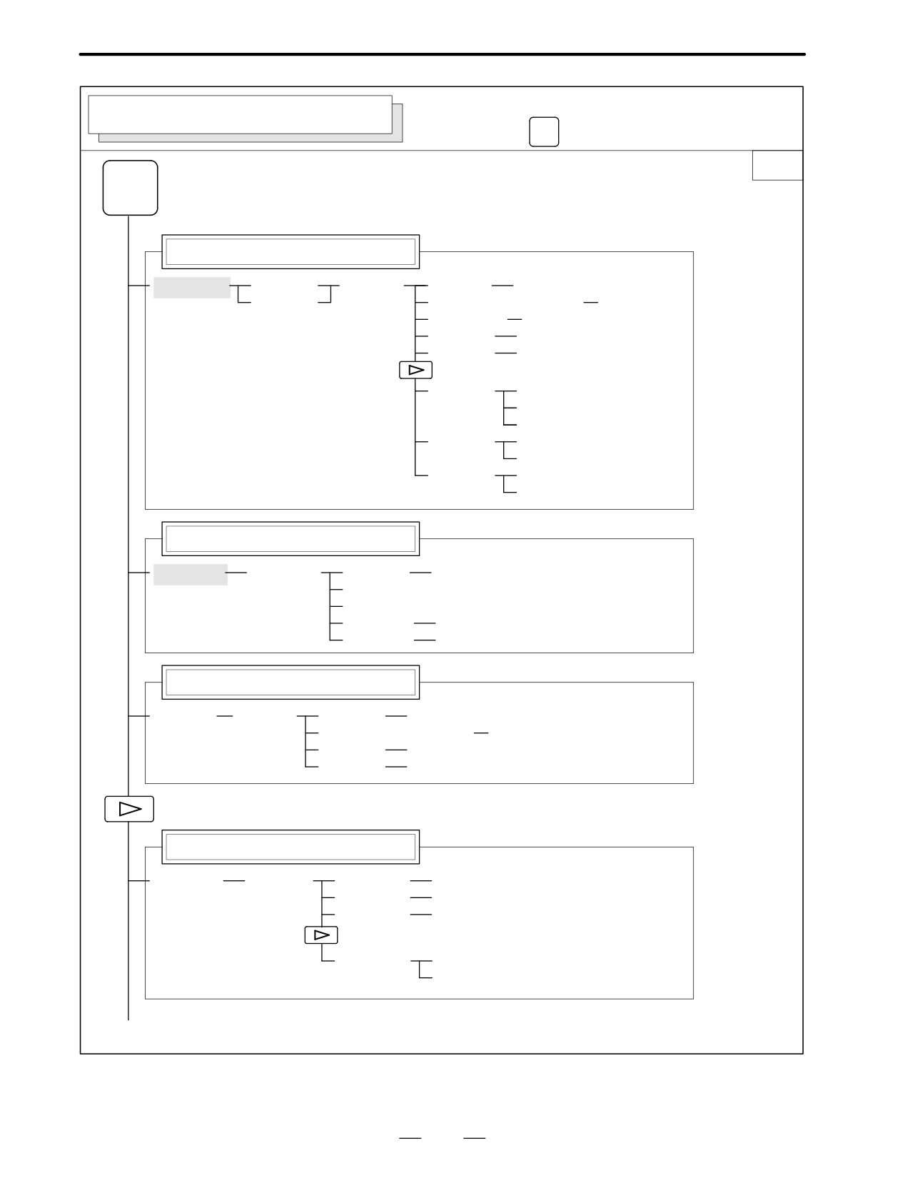
B-62445E/03
1. DISPLAY AND OPERATION OF CRT/MDI
Soft key transition triggered by the
OFFSET/SETTING SCREEN (T series)
function key
OFFSET
SETTING
1/2
OFFSET
SETTING
Tool offset screen
[OFFSET]
[WEAR]
[(OPRT)]
(Number)
[NO SRH]
[GEOM]
(Axis name and numeral)
[MEASUR]
(Axis name)
[INP.C.]
(Numeral)
[+INPUT]
(Numeral)
[INPUT]
[CLEAR]
[ALL]
[WEAR]
[GEOM]
[READ]
[CAN]
[EXEC]
[PUNCH]
[CAN]
[EXEC]
Setting screen
[SETING]
[(OPRT)]
(Number)
[NO SRH]
[ON:1]
[OFF:0]
(Numeral)
[+INPUT]
(Numeral)
[INPUT]
Work coordinate system setting screen
[WORK]
[(OPRT)]
(Number)
[NO SRH]
(Axis name and numeral)
[MEASUR]
(Numeral)
[+INPUT]
(Numeral)
[INPUT]
Macro variables display screen
[MACRO]
[(OPRT)]
(Number)
[NO SRH]
(Axis name)
[INP.C.]
(Numeral)
[INPUT]
[PUNCH]
[CAN]
[EXEC]
(1)(Continued on the next page)
13

1. DISPLAY AND OPERATION OF CRT/MDI
B-62445E/03
2/2
(1)
Menu programming screen
[MENU]
[(OPRT)]
(Number)
[SELECT]
Software operator’s panel screen
[OPR]
Tool life management setting screen
[TOOLLF]
[(OPRT)]
(Number)
[NO SRH]
[CLEAR]
[CAN]
[EXEC]
(Numeral)
[INPUT]
Y axis tool offset screen
[OFST
.2]
[WEAR]
[(OPRT)]
(Number)
[NO SRH]
[GEOM]
(Axis name and numeral)
[MEASUR]
(Axis name)
[INP.C.]
(Numeral)
[+INPUT]
(Numeral)
[INPUT]
[CLEAR]
[ALL]
[WEAR]
[GEOM]
[READ]
[CAN]
[EXEC]
[PUNCH]
[CAN]
[EXEC]
Workpiece shift screen
[WK.SHFT]
[(OPRT)]
(Numeral)
[+INPUT]
(Numeral)
[INPUT]
14
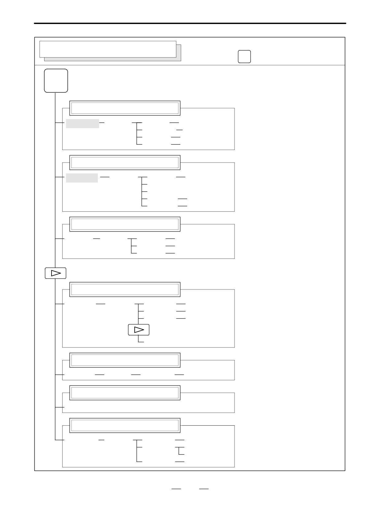
B-62445E/03
1. DISPLAY AND OPERATION OF CRT/MDI
Soft key transition triggered by the
OFFSET/SETTING SCREEN (M series)
function key
OFFSET
SETTING
OFFSET
SETTING
Tool offset screen
[OFFSET]
[(OPRT)]
(Number)
[NO SRH]
(Axis name)
[INP.C.]
(Numeral)
[+INPUT]
(Numeral)
[INPUT]
Setting screen
[SETING]
[(OPRT)]
(Number)
[NO SRH]
[ON:1]
[OFF:0]
(Numeral)
[+INPUT]
(Numeral)
[INPUT]
Work coordinate system setting screen
[WORK]
[(OPRT)]
(Number)
[NO SRH]
(Numeral)
[+INPUT]
(Numeral)
[INPUT]
Macro variables display screen
[MACRO]
[(OPRT)]
(Number)
[NO SRH]
(Axis name)
[INP.C.]
(Numeral)
[INPUT]
[PUNCH]
Menu programming screen
[MENU]
[(OPRT)]
(Number)
[SELECT]
Software operator’s panel screen
[OPR]
Tool life management setting screen
[TOOLLF]
[(OPRT)]
(Number)
[NO SRH]
[CLEAR]
[CAN]
[EXEC]
(Numeral)
[INPUT]
15
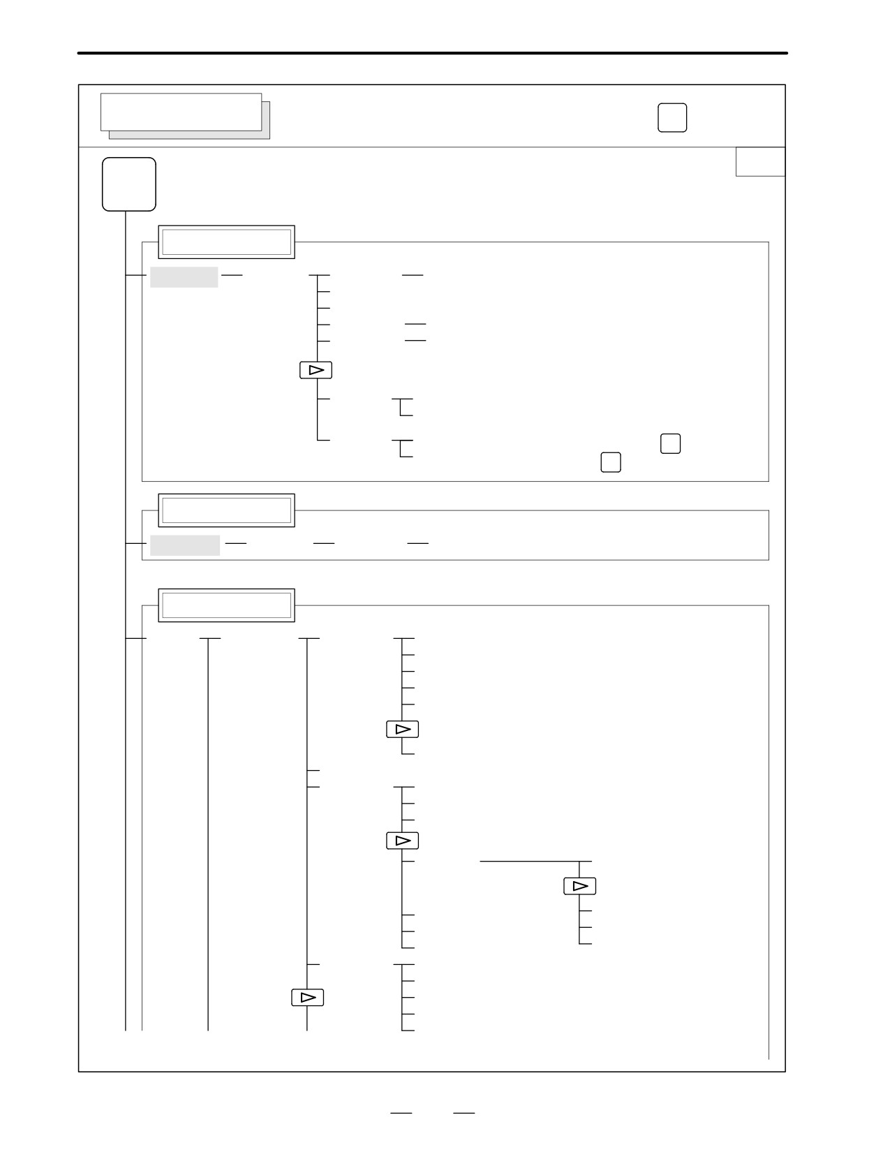
1. DISPLAY AND OPERATION OF CRT/MDI
B-62445E/03
SYSTEM SCREEN
Soft key transition triggered by the function key
SYSTEM
1/3
SYSTEM
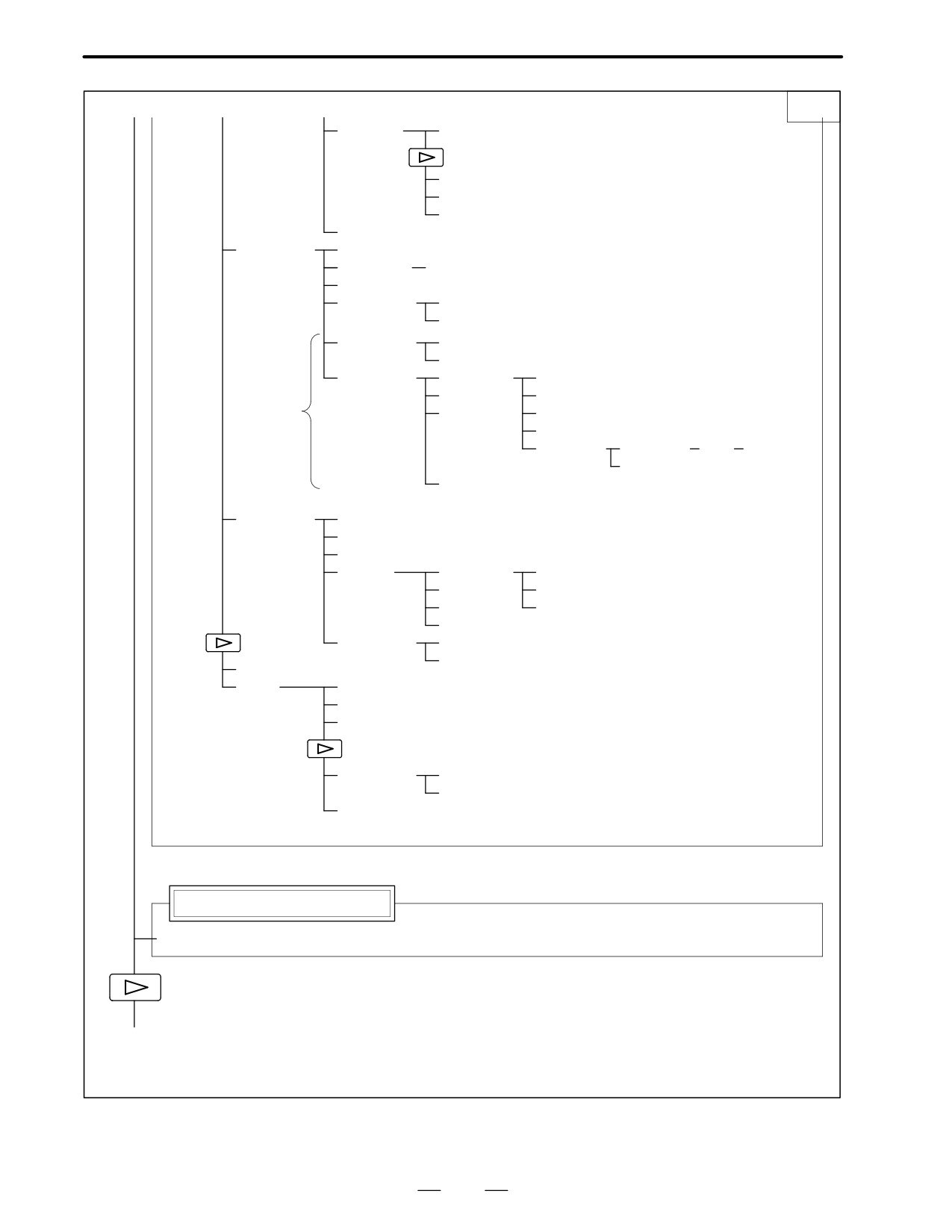
Parameter screen
[PARAM]
[(OPRT)]
(Number)
[NO SRH]
[ON:1]
[OFF:0]
(Numeral)
[+INPUT]
(Numeral)
[INPUT]
[READ]
[CAN]
[EXEC]
[PUNCH]
[CAN]
To enter a file number: Press
N
, enter a file
[EXEC]
INPUT
number, then press
on the PRGRM screen
Diagnosis screen
[DGNOS]
[(OPRT)]
(Number)
[NO SRH]
PMC screen
[PMC]
[PMCLAD]
[SEARCH]
[TOP]
[BOTTOM]
[SRCH]
[W-SRCH]
[N-SRCH]
[F-SRCH]
[ADRESS]/[SYMBOL]
[TRIGER]
[TRGON]
[TRGOFF]
[START]
[DUMP]
[SEARCH]
[BYTE]
[DPARA]/[NDPARA]
[WORD]
[TRGSRC]
[D.WORD]
[INIT]
[WINDOW]
[DIVIDE]
[CANCEL]
[DELETE]
[SELECT]
[WIDTH]
(1)
(2)
(3)
(Continued on the next page)
16
B-62445E/03
1. DISPLAY AND OPERATION OF CRT/MDI
(1)
(2)
(3)
2/3
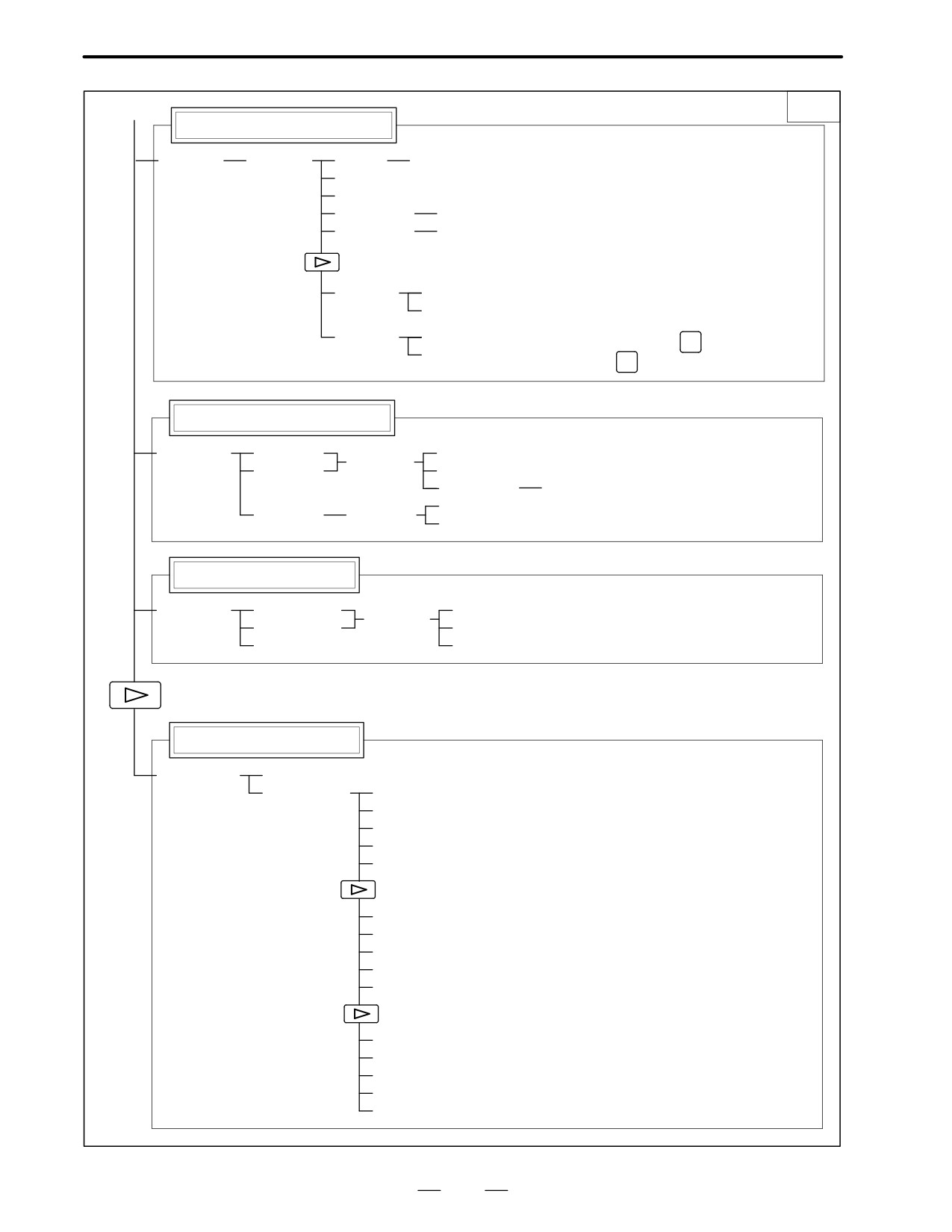
[DUMP]
[SEARCH]
[BYTE]
[WORD]
[D.WORD]
[DRARA]/[NDPARA]
[PMCDGN]
[TITLE]
[STATUS]
[SEARCH]
[ALARM]
[TRACE]
[T.DISP]/[TRCPRM]
[EXEC]
[M.SRCH]
[SEARCH]
[INPUT]
[ANALYS]
[SCOPE]
[SGNPRM]
With
[DELETE]
[START]/[STOP]
PMC-RC
[INIT]
[T-SRCH]
only
[ADRESS]/[SYMBOL]
[EXCHG]
[SELECT]
[TO]
[EXEC]
[CANCEL]
[ADRESS]/[SYMBOL]
[PMCPRM]
[TIMER]
[COUNTR]
[KEEPRL]
[DATA]
[G.DATA]
[C.DATA]
[G.CONT]
[G-SRCH]
[NO.SRH]
[SEARCH]
[INIT]
[SETTING]
[YES]/[MANUAL]/[ROM]
[NO]/[AUTO]/[RAM]
[STOP]/[RUN]
[I/O]
[EXEC]
[CANCEL]
(No.)
[SPEED]
[INPUT]
[INIT]
[MDI]/[ROM]
System configuration screen
[SYSTEM]
(4)
(Continued on the next page)
17
1. DISPLAY AND OPERATION OF CRT/MDI
B-62445E/03
(4)
3/3
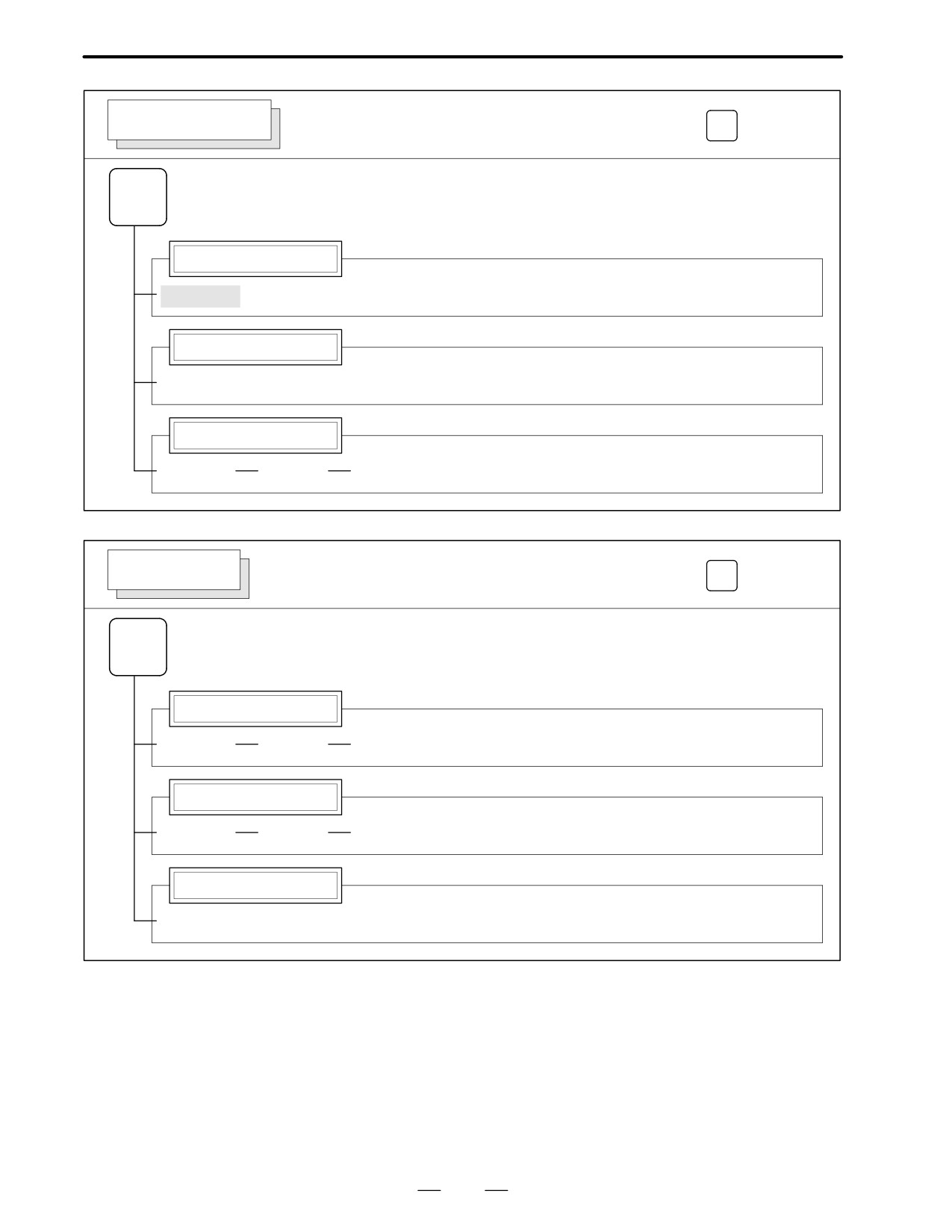
Pitch error compensation screen
[PITCH]
[(OPRT)]
(No.)
[NO SRH]
[ON:1]
[OFF:0]
(Numeral)
[+INPUT]
(Numeral)
[INPUT]
[READ]
[CAN]
[EXEC]
[PUNCH]
[CAN]
To enter a file number: Press
N
, enter a file
[EXEC]
INPUT
number, then press
on the PRGRM screen
Servo parameter screen
[SV.PRM]
[SV.SET]
[ON:1]
[(OPRT)]
[SV.TUN]
[OFF:0]
(Numeral)
[INPUT]
[TRACE]
[SV.TRC]
[(OPRT)]
[TRNSF]
Spindle parameter screen
[SP.PRM]
[SP.SET]
[ON:1]
[(OPRT)]
[SP.TUN]
[OFF:0]
[SP.MON]
[INPUT]
Waveform diagnosis screen
[W.DGNS]
[W.PRM]
[W.GRPH]
[STSRT]
[TIME→]
[←TIME]
[H-DOBL]
[H-HALF]
[STSRT]
[CH-1↑]
[CH-1↓]
[V-DOBL]
[V-HALF]
[STSRT]
[CH-2↑]
[CH-2↓]
[V-DOBL]
[V-HALF]
18
B-62445E/03
1. DISPLAY AND OPERATION OF CRT/MDI
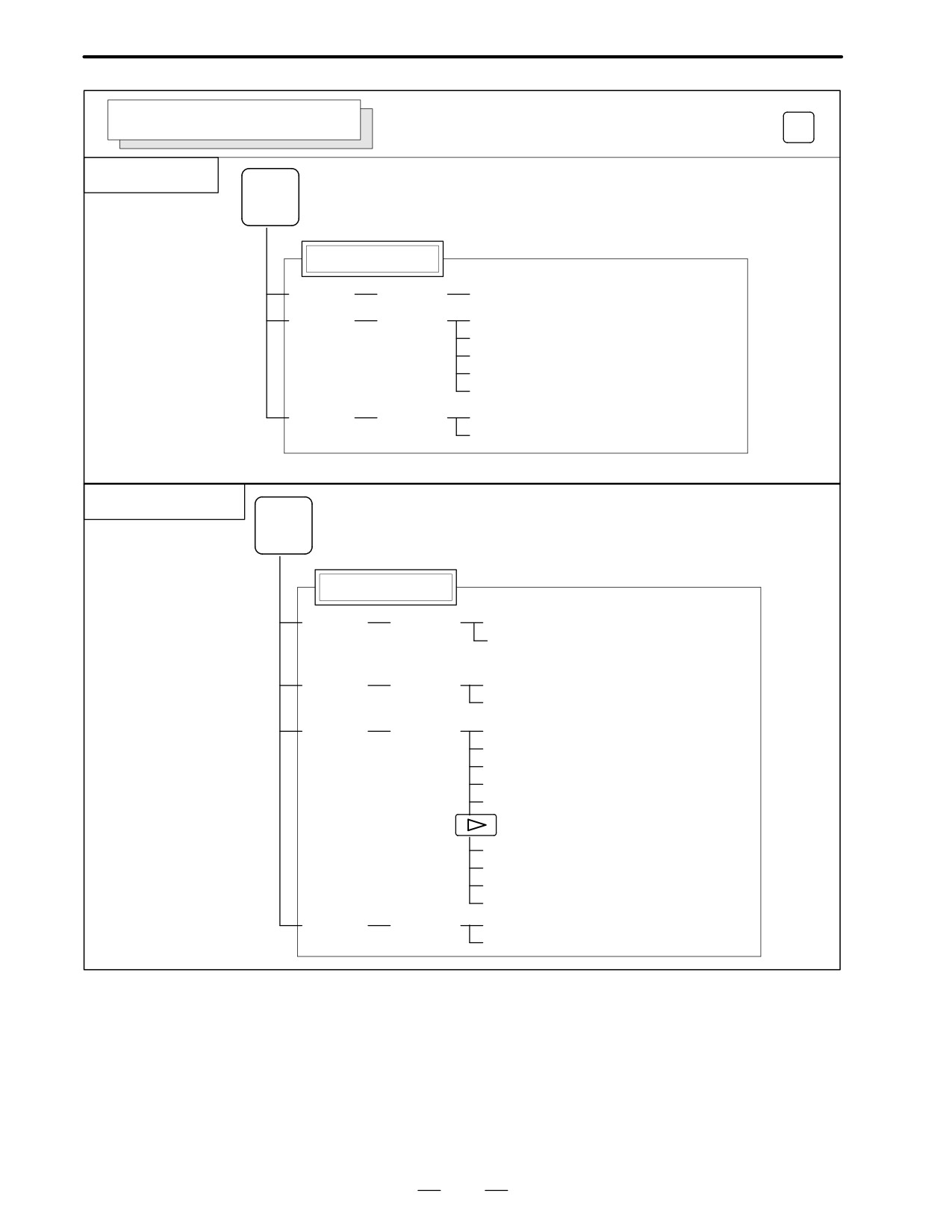
MESSAGE SCREEN
Soft key transition triggered by the function key
MESSAGE
MESSAGE
Alarm display screen
[ALARM]
Message display screen
[MSG]
Alarm history screen
[HISTRY]
[(OPRT)]
[CLEAR]
HELP SCREEN
Soft key transition triggered by the function key
HELP
HELP
Alarm detail screen
[1 ALAM]
[(OPRT)]
[SELECT]
Operation method screen
[2 OPR]
[(OPRT)]
[SELECT]
Parameter table screen
[3 PARA]
19
1. DISPLAY AND OPERATION OF CRT/MDI
B-62445E/03
GRAPHIC SCREEN (T series)
Soft key transition triggered by the function key
GRAPH
Tool path graphics
GRAPH
Mode 0
Tool path graphics
[G.PRM]
[(OPRT)]
[NORMAL]
[GRAPH]
[(OPRT)]
[HEAD]
[ERASE]
[PROCES]
[EXEC]
[STOP]
[ZOOM]
[(OPRT)]
[ACT]
[HI/LO]
A.ST/Path graphics
GRAPH
Mode 1 to 3
A.ST/Path graphics
[G.PRM]
[(OPRT)]
[NORMAL]
[ENTRY]
[A.PRM]
[(OPRT)]
[NORMAL]
[ENTRY]
[GRAPH]
[(OPRT)]
[HEAD]
[ERASE]
[PROCES]
[EXEC]
[STOP]
[SIDE]
[FRONT]
[OPEN]
[ZOOM]
[(OPRT)]
[EXEC]
[HI/LO]
20