FANUC Series 0i-MODEL D, Series 0i Mate-MODEL D. For Lathe System USER’S MANUAL - page 18

B.DIFFERENCES FROM SERIES 0i-C APPENDIX
B-64304EN-1/01
Function
Series 0i-C
Series 0i-D
Setting of
-
This item is determined by using bit 7
-
Bit 7 (NDI) of parameter No. 8004 is
diameter/radius
(NDI) of parameter No. 8004 and bit 1
not available. The item is determined
specification for the
(CDI) of parameter No. 8005 in
by bit 1 (CDI) of parameter No. 8005.
amount of travel and
combination.
feedrate when diameter
Bit 1 (CDI) of parameter No. 8005
programming is specified
In PMC axis control, when diameter
for a PMC-controlled axis
programming is specified for a
PMC-controlled axis:
0: The amount of travel and feedrate are
each specified with a radius.
1: The amount of travel is specified with
a diameter while the feedrate is
specified with a radius.
Individual output of the
-
Depends on bit 7 (MFD) of parameter
-
Bit 7 (MFD) of parameter No. 8005 is
auxiliary function
No. 8005.
not available.
The individual output of the auxiliary
Bit 7 (MFD) of parameter No. 8005
function for PMC axis control function
The individual output of the auxiliary function
is enabled.
for PMC axis control function is:
0: Disabled.
1: Enabled.
Function to exert position
-
Depends on bit 4 (EVP) of parameter No.
-
Depends on bit 4 (EVP) of parameter
control for the speed
8005.
No. 8005. Note that, for the EVP=1
command (10h)
setting to take effect, 1 must be set in
Bit 4 (EVP) of parameter No. 8005
bit 2 (VCP) of parameter No. 8007.
The speed of PMC axis control is specified
by:
Bit 2 (VCP) of parameter No. 8007
0: Speed command.
The speed command in PMC axis control
1: Position command.
is:
0: FS10/11 type.
1: FS0 type.
In-position check for an
-
Depends on bit 2 (IPA) of parameter No.
-
Bit 2 (IPA) of parameter No. 8006 is
axis controlled only by
8006.
not available. Parameter No. 1010 is
PMC axis control
not available, either.
Bit 2 (IPA) of parameter No. 8006
The check is performed when no
In the case of an axis controlled only by
move command is specified for the
PMC axis control (see parameter No. 1010),
PMC axis. Otherwise, the processing
in-position check is:
is determined by bit 6 (NCI) of
0: Performed when no move command is
parameter No. 8004.
specified for the PMC axis.
1: Always not performed.
Bit 6 (NCI) of parameter No. 8004
When the PMC-controlled axis is
decelerated, in-position check is:
0: Performed.
1: Not performed.
- 494 -

B-64304EN-1/01
APPENDIX B.DIFFERENCES FROM SERIES 0i-C
Function
Series 0i-C
Series 0i-D
No in-position check
-
Depends on bit 0 (NIS) of parameter No.
-
Bit 0 (NIS) of parameter No. 8007 is
signal for a
8007.
not available.
PMC-controlled axis and
The no in-position check signal
no in-position check
Bit 0 (NIS) of parameter No. 8007
NOINPS<G023.5> and no in-position
signals for individual
For in-position check for a PMC axis, the no
check signals for individual axes
axes
in-position check signal NOINPS<G023.5>
NOINP1<G359> to NOINP5<G359>
and no in-position check signals for
are disabled for in-position check for a
individual axes NOINP1<G359> to
PMC axis.
NOINP5<G359> are:
0: Disabled.
1: Enabled.
Minimum speed for rapid
-
Set the value in parameter No. 8021.
-
Parameter No. 8021 is not available.
traverse override in PMC
The minimum speed for rapid traverse
axis control
override cannot be set.
Differences regarding 2-path control
Function
Series 0i-C
Series 0i-D
Relationship with
-
PMC axis control can also be applied to
-
PMC axis control cannot be applied to
composite control
axes subject to composite control.
axes subject to composite control.
Setting when groups
-
1 (group A) to 4 (group D) are set in
-
5 (group A for the path 2) to 8 (group D
A to D in the path 2
parameter No. 8010 for the path 2.
for the path 2) are set in the axis
is used.
parameter No. 8010 controlled in the
path 2.
Parameter No. 8010
Specify the DI/DO group to be used to
specify a command for each
PMC-controlled axis.
B.26.2 Differences in Diagnosis Display
None.
- 495 -

B.DIFFERENCES FROM SERIES 0i-C APPENDIX
B-64304EN-1/01
B.27 EXTERNAL SUBPROGRAM CALL (M198)
B.27.1 Differences in Specifications
Function
Series 0i-C
Series 0i-D
Address P format
-
Depends on bit 2 (SBP) of parameter
-
To call a subprogram, the program
when calling a
No. 3404.
number must always be specified in
subprogram on the
address P.
memory card (file
Bit 2 (SBP) of parameter No. 3404
When calling a subprogram on the
number
In the external device subprogram call
memory card, the processing is not
specification/program
M198, address P is specified using:
dependent on the setting of bit 2 (SBP)
number specification)
0: File number.
of parameter No. 3404.
1: Program number.
Multiple call alarm
If a subprogram called by an external subprogram call specifies a further external
subprogram call, the following alarms are issued, respectively:
-
Alarm PS0210
-
Alarm PS1080
External subprogram
-
Enabled.
-
Depends on bit 1 (MDE) of parameter
call in MDI mode
No. 11630.
Bit 1 (MDE) of parameter No. 11630
In MDI mode, an external device
subprogram call (M198 command) is:
0: Disabled.
(Alarm PS1081 is issued.)
1: Enabled.
B.27.2 Differences in Diagnosis Display
None.
- 496 -

B-64304EN-1/01
APPENDIX B.DIFFERENCES FROM SERIES 0i-C
B.28 SEQUENCE NUMBER SEARCH
B.28.1 Differences in Specifications
Function
Series 0i-C
Series 0i-D
Return from a
-
The calling program is searched from
-
The calling program is searched in a
subprogram to the
the beginning, and control is returned to
forward direction from the block that
calling program's
the first block found to have sequence
called the subprogram, and control is
block that has a
number Nxxxxx.
returned to the first block found to have
specified sequence
sequence number Nxxxxx.
number
If the specified sequence number is not
Sequence number
found, the calling program is searched
search when (M99
from the beginning, and control is
Pxxxxx) is executed
returned to the first block found to have
sequence number Nxxxxx.
Example) Main program
Sub program
O0001 ;
O9001 ;
N100 ; (1)
M99 P100 ;
N100 ; (2)
M98 P9001 ;
N100 ; (3)
N100 ; (4)
M30 ;
-
[For Series 0i-C]
-
[For Series 0i-D]
Control is returned to block (1).
Control is returned to block (3).
WARNING
Be sure to avoid writing two or more identical sequence numbers in a program.
Doing so may cause the search to find unintended blocks.
B.28.2 Differences in Diagnosis Display
None.
- 497 -

B.DIFFERENCES FROM SERIES 0i-C APPENDIX
B-64304EN-1/01
B.29 STORED STROKE CHECK
B.29.1 Differences in Specifications
Function
Series 0i-C
Series 0i-D
Stored stroke check
-
This function is always enabled for all
-
It is possible to select whether to
immediately following
axes.
enable or disable the function on an
powering on
axis-by-axis basis using bit 0 (DOT) of
parameter No. 1311.
Bit 0 (DOT) of parameter No. 1311
The stored stroke limit check immediately
following powering on is:
0: Disabled.
1: Enabled.
NOTE
This function stores machine coordinates
using software and therefore imposes a
burden on the system. Disable the
function for those axes that do not require
it.
Movements made while the power is
off are not reflected on the machine
coordinate system immediately after
powering on.
-
Machine coordinates are set upon
-
Machine coordinates are set upon
powering on.
powering on.
Absolute and relative coordinates are not
Absolute and relative coordinates are
set.
set based on these machine
(They are set when the absolute position
coordinates.
detector is provided.)
Y and J address
Not available.
-
Available for both the T series and M
specification using
series.
G22
Overtravel alarm
-
Stored stoke check 2 does not support
-
Stored stoke check 2 also supports bit
bit 7 (BFA) of parameter No. 1300.
7 (BFA) of parameter No. 1300.
Therefore, if an interference alarm
Setting 1 in BFA allows the tool to stop
occurs, the tool stops after entering the
before entering the prohibited area,
prohibited area.
thus eliminating the need to make the
This makes it necessary to make the
prohibited area slightly larger than
prohibited area slightly larger than
actually necessary.
actually necessary.
Bit 7 (BFA) of parameter No. 1300
If a stored stoke check 1, 2, or 3 alarm
occurs, if an interference alarm occurs with
the inter-path interference check function
(T series), or if an alarm occurs with
chuck/tail stock barrier (T series), the tool
stops:
0: After entering the prohibited area.
1: Before entering the prohibited area.
- 498 -

B-64304EN-1/01
APPENDIX B.DIFFERENCES FROM SERIES 0i-C
Function
Series 0i-C
Series 0i-D
Operation
-
When the operation is resumed, the tool
-
When the operation is resumed, the
continuation after
moves the remaining travel distance of
tool moves toward the end point of the
automatic alarm
the block that caused the soft OT.
block that caused the soft OT, causing
cancellation when a
Therefore, the program can be
another soft OT and making it
soft OT1 alarm is
continued if the tool is moved through
impossible to continue the program.
issued during the
manual intervention beyond the
For details, refer to "STORED
execution of an
remaining travel distance.
STROKE CHECK 1" in "CONNECTION
absolute command in
MANUAL (FUNCTION)" (B-64303EN).
automatic operation
B.29.2 Differences in Diagnosis Display
None.
- 499 -
B.DIFFERENCES FROM SERIES 0i-C APPENDIX
B-64304EN-1/01
B.30 STORED PITCH ERROR COMPENSATION
B.30.1 Differences in Specifications
Function
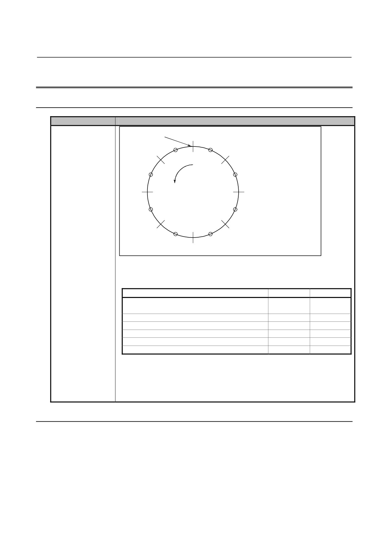
Explanation
Value of parameter
Reference position
0.0
No. 3621 for the
setting of a rotary axis
45.0
315.0
(type A)
(61)
(68)
(60)
(62)
(67)
(+)
90.0
270.0
(63)
(66)
(64)
(65)
225.0
135.0
Compensation values are output at
the positions indicated by ○.
180.0
-
Amount of movement per rotation:
360°
-
Interval between pitch error compensation positions:
45°
-
Number of the compensation position of the reference position:
60
In the above case, the values of the parameters are as follows.
Parameter
Series 0i-C
Series 0i-D
No. 3620: Number of the compensation position of
60
60
the reference position
No. 3621: Smallest compensation position number
60
61
No. 3622: Largest compensation position number
68
68
No. 3623: Compensation magnification
1
1
No. 3624: Interval between compensation positions
45000
45000
No. 3625: Amount of movement per rotation
360000
360000
The value of parameter No. 3621 is as follows.
Series 0i-C
= Number of the compensation position of the reference position (parameter No. 3620)
Series 0i-D
= Number of the compensation position of the reference position (parameter No. 3620) +
1
B.30.2
Differences in Diagnosis Display
None.
- 500 -

B-64304EN-1/01
APPENDIX B.DIFFERENCES FROM SERIES 0i-C
B.31 SCREEN ERASURE FUNCTION AND AUTOMATIC
SCREEN ERASURE FUNCTION
B.31.1 Differences in Specifications
Function
Series 0i-C
Series 0i-D
Behavior of the
-
When an alarm is issued (including one
-
When an alarm is issued (including one
manual screen
associated with the other path), the
associated with the other path), the
erasure function
manual screen erasure function is
manual screen erasure function is
("<CAN> + function
enabled.
disabled.
key") when an alarm
("<CAN> + function key" erases the
("<CAN> + function key" does not
is issued
screen.)
erase the screen.)
Redisplay of the
-
When the operation mode is switched while the screen is erased:
screen upon mode
The screen is not redisplayed.
The screen is redisplayed.
switching
(The screen remains erased.)
Function key input
-
Select the behavior using bit 2 (NFU) of
-
Bit 2 (NFU) of parameter No. 3209 is
when the screen is
parameter No. 3209.
not available.
erased or displayed
The tool always behaves as when 1 is
Bit 2 (NFU) of parameter No. 3209
set in bit 2 (NFU) of parameter No.
When a function key is pressed to erase or
3209.
display the screen for the screen erasure or
automatic screen erasure function, the
screen change using a function key is:
0: Performed.
1: Not performed.
Time before the
-
Set the value in parameter No.3123.
automatic screen
The value range is 1 to 255 (minutes).
The value range is 1 to 127 (minutes).
erasure function starts
B.31.2 Differences in Diagnosis Display
None.
- 501 -

B.DIFFERENCES FROM SERIES 0i-C APPENDIX
B-64304EN-1/01
B.32 RESET AND REWIND
B.32.1 Differences in Specifications
Function
Series 0i-C
Series 0i-D
Modal data when
-
If reset occurs during the execution of a block, the states of the modal G codes and
reset during the
modal addresses (N, F, S, T, M, etc.) specified in that block are handled as follows.
execution of a block
Maintained.
Not maintained. The states return to
those of the modal data specified in the
preceding blocks.
(The modal data is updated after the
specified block is fully executed.)
Example) If reset occurs before
positioning is completed in the N2 block in
the program shown below, the T code and
offset return to the data of the preceding
tool (T0101) data.
N1 G00 X120. Z0. T0101 ;
;
N2 G00 X180. Z20. T0202 ;
;
Information in a block
-
The information in the block may or may
-
The information in the block is not held
that is pre-read when
not be held depending on whether MDI
regardless whether MDI mode is in
a reset is made during
mode is in progress.
progress.
an automatic
In MDI mode
operation (contents of
The information in the block is held.
the buffer)
In modes other than MDI mode
The information in the block is not
held.
B.32.2 Differences in Diagnosis Display
None.
- 502 -

B-64304EN-1/01
APPENDIX B.DIFFERENCES FROM SERIES 0i-C
B.33 MANUAL ABSOLUTE ON AND OFF
B.33.1 Differences in Specifications
Function
Series 0i-C
Series 0i-D
Absolute coordinates
-
If tool compensation is automatically changed when the manual absolute signal
during automatic tool
*ABSM(Gn006.2) is set to 1, absolute coordinates are handled as follows.
compensation change
Absolute coordinates are not changed.
Absolute coordinates are changed
according to the amount of tool
compensation resulting from the coordinate
shift.
B.33.2 Differences in Diagnosis Display
None.
- 503 -

B.DIFFERENCES FROM SERIES 0i-C APPENDIX
B-64304EN-1/01
B.34 MEMORY PROTECTION SIGNAL FOR CNC PARAMETER
B.34.1 Differences in Specifications
Function
Series 0i-TTC
Series 0i-D
Memory protection
-
The signal is different for each path.
-
The signal is common to all paths.
signal for CNC
parameter
KEYP, KEY1 to KEY4
<G046.0, G046.3 to
G046.6>
Parameter to enable
-
Enable or disable the signal using bit 7
-
Enable or disable the signal using bit 0
the KEYP signal
(PK5) of parameter No. 3292. This is
(PKY) of parameter No. 3299. This is
a bit path parameter.
a bit system common parameter.
B.34.2 Differences in Diagnosis Display
None.
- 504 -

B-64304EN-1/01
APPENDIX B.DIFFERENCES FROM SERIES 0i-C
B.35 EXTERNAL DATA INPUT
B.35.1 Differences in Specifications
Function
Series 0i-C
Series 0i-D
Number of external
-
[Number of messages that can be set at
-
[Number of messages that can be set
alarm messages and
a time]
at a time]
message length
Up to 4 messages
Depends on bit 1 (M16) of parameter
[Length of a message]
No. 11931. When 0 is set, the
Up to 32 characters
processing is the same as Series 0i-C.
Bit 1 (M16) of parameter No. 11931
The maximum number of external alarm
messages or external operator messages
that can be displayed in connection with
external data input or external messages
is:
0:
4.
1:
16.
[Length of a message]
Up to 32 characters
Display format of
-
[Alarm numbers that can be sent]
-
Depends on bit 0 (EXA) of parameter
external alarm
0 to 999
No. 6301.
messages
[How to distinguish these numbers from
general alarm numbers]
Bit 0 (EXA) of parameter No. 6301
Add 1000 to the number sent
Select the external alarm message
specification.
0: The alarm numbers that can be sent
range from 0 to 999. The CNC
displays an alarm number, with 1000
added to the number following the
character string "EX".
1: The alarm numbers that can be sent
range from 0 to 4095. The CNC
displays an alarm number, with the
character string "EX" added in front of
it.
Number of external
-
Depends on bit 0 (OM4) of parameter
-
Bit 0 (OM4) of parameter No. 3207 is
operator messages
No. 3207.
not available.
and message length
[Number of messages that can be set
Bit 0 (OM4) of parameter No. 3207
at a time]
The external operator message screen can
Depends on bit 1 (M16) of parameter
display:
No. 11931. Select either up to 4 or 16
0: Up to 256 characters in up to 1
messages.
message.
[Length of a message]
1: Up to 64 characters in up to 4
256 characters or less
messages.
- 505 -

B.DIFFERENCES FROM SERIES 0i-C APPENDIX
B-64304EN-1/01
Function
Series 0i-C
Series 0i-D
Display format of
-
[Message numbers that can be sent]
-
Depends on bit 1 (EXM) of parameter
external operator
0 to 999
No. 6301. When 0 is set, the
messages
[How to distinguish these numbers from
processing is the same as Series 0i-C.
alarm and other numbers]
Messages from 0 to 99
Bit 1 (EXM) of parameter No. 6301
The message is displayed on the
Select the external operator message
screen along with the number. The
specification.
CNC adds 2000 to this number for
0: The message numbers that can be
distinction.
sent range from 0 to 999.
Messages from 100 to 999
A message from 0 to 99 is displayed on
Only the message is displayed on the
the screen along with the number.
screen without the number.
The CNC adds 2000 to this number for
distinction.
As for the messages from 100 to 999,
only the message is displayed on the
screen without the number.
1: The message numbers that can be
sent range from 0 to 4095.
A message from 0 to 99 is displayed on
the screen along with the number.
The CNC adds the character string
"EX" in front of the number.
As for the messages from 100 to 4095,
only the message is displayed on the
screen without the number.
Data range of external
Parameter No. 6310
operator message
The data range of external operator message numbers is as follows.
numbers
-
0 to 1000
-
0 to 4096
When an external
-
An alarm is not issued; the search is not
-
Alarm DS0059 is issued.
program number
done, either.
search is done with 0
set as the program
number
Input of an external
-
The input is ignored without issuing an
-
Alarm DS1121 is issued.
tool offset for an
alarm.
invalid function
compensation value
Number of history
-
Make a selection using bit 7 (MS1) and
-
Bit 7 (MS1) and bit 6 (MS0) of
messages for external
bit 6 (MS0) of parameter No. 3113 in
parameter No. 3113 are not available.
operator messages
combination.
[Number of history messages]
and message length
Up to 32
[History message length of a message]
Up to 256 characters
B.35.2 Differences in Diagnosis Display
None.
- 506 -

B-64304EN-1/01
APPENDIX B.DIFFERENCES FROM SERIES 0i-C
B.36 DATA SERVER FUNCTION
B.36.1 Differences in Specifications
Function
Series 0i-C
Series 0i-D
Memory operation
-
The memory operation mode is not
-
In the memory operation mode, the
mode
supported.
following operations can be performed
for a program registered with the data
server:
1. Select the program on the data
server as the main program and run
it in the memory mode.
2. Call a subprogram or custom
macro in the same directory as the
main program on the data server.
3. Edit the program, including
inserting, deleting, and replacing
words.
Simultaneous call
In a 2-path system, a simultaneous external subprogram call (M198) of a data server
from two paths
program from both paths is:
-
Allowed under the following conditions.
-
Not allowed.
[Storage mode]
Use the subprogram/custom macro call
Both paths must use the same work
for the memory operation mode
directory.
instead.
[FTP mode]
Both paths must use the same
connection host.
B.36.2 Differences in Diagnosis Display
None.
- 507 -

B.DIFFERENCES FROM SERIES 0i-C APPENDIX
B-64304EN-1/01
B.37 POWER MATE CNC MANAGER
B.37.1 Differences in Specifications
Function
Series 0i-C
Series 0i-D
4-slave display
-
By setting 1 in bit 0 (SLV) of parameter
-
Bit 0 (SLV) of parameter No. 0960 is
function
No. 0960, it is possible to split the
not available.
screen into four windows, enabling up
One slave is always displayed.
to four slaves to be displayed.
When there is more than one slave,
you switch the active slave by using the
Bit 0 (SLV) of parameter No. 0960
relevant soft key.
When Power Mate CNC Manager is
selected, the screen:
0: Displays one slave.
1: Is split into four windows, enabling up to
four slaves to be displayed.
B.37.2 Differences in Diagnosis Display
None.
- 508 -

B-64304EN-1/01
APPENDIX B.DIFFERENCES FROM SERIES 0i-C
B.38 CHUCK/TAIL STOCK BARRIER
B.38.1 Differences in Specifications
Function
Series 0i-C
Series 0i-D
Overtravel alarm
-
Bit 7 (BFA) of parameter No. 1300 is
-
Bit 7 (BFA) of parameter No. 1300 is
not supported.
supported.
Therefore, if an interference alarm
Setting 1 in BFA allows the tool to stop
occurs, the tool stops after entering the
before entering the prohibited area,
prohibited area.
thus eliminating the need to make the
This makes it necessary to make the
prohibited area slightly larger than
prohibited area slightly larger than
actually necessary.
actually necessary.
Bit 7 (BFA) of parameter No. 1300
If a stored stoke check 1, 2, or 3 occurs, if
an interference alarm occurs with the
inter-path interference check function (T
series), or if an alarm occurs with chuck/tail
stock barrier (T series), the tool stops:
0: After entering the prohibited area.
1: Before entering the prohibited area.
B.38.2 Differences in Diagnosis Display
None.
- 509 -

B.DIFFERENCES FROM SERIES 0i-C APPENDIX
B-64304EN-1/01
B.39 THREADING CYCLE RETRACT (CANNED CUTTING
CYCLE/MULTIPLE REPETITIVE CANNED CUTTING
CYCLE)
B.39.1 Differences in Specifications
Function
Series 0i-C
Series 0i-D
Return position after
-
The tool returns to the start point of the
-
The tool returns to the start point of the
chamfering in multiple
current cycle. For example, if it is the
threading cycle. This means that the
repetitive threading
nth cycle, the tool returns to the position
tool returns to the position where it was
cycle (G76)
where the nth cut has been made.
before cutting, no matter how many
cycles it has undergone.
Retraction after
-
The specifications are as follows.
-
Depends on bit 0 (CFR) of parameter
chamfering
No. 1611. When 0 is set, the
[Acceleration/deceleration type]
processing is the same as Series 0i-C.
Acceleration/deceleration after
interpolation for threading is used.
Bit 0 (CFR) of parameter No. 1611
[Time constant]
In threading cycle G92 or G76, retraction
The time constant for threading
after threading uses:
(parameter No. 1626) is used.
0: Type of acceleration/deceleration after
[Feedrate]
interpolation for threading, together with
The feedrate set in parameter No. 1466
the threading time constant (parameter
is used.
No.1626) and the feedrate set in
parameter No.1466.
1: Type of acceleration/deceleration after
interpolation for rapid traverse, together
with the rapid traverse time constant
and the rapid traverse rate.
B.39.2 Differences in Diagnosis Display
None.
- 510 -

B-64304EN-1/01
APPENDIX B.DIFFERENCES FROM SERIES 0i-C
B.40 POLAR COORDINATE INTERPOLATION
B.40.1 Differences in Specifications
Function
Series 0i-C
Series 0i-D
Coordinate system
-
Not available.
-
Enable or disable the function using bit
shift during polar
2 (PLS) of parameter No. 5450.
coordinate
interpolation (polar
Bit 2 (PLS) of parameter No. 5450
coordinate
The polar coordinate interpolation shift
interpolation shift
function is:
function)
0: Not used.
1: Used.
This enables machining using the
workpiece coordinate system with a
desired point which is not the center of the
rotation axis set as the origin of the
coordinate system in polar coordinate
interpolation.
For details, refer to "POLAR
COORDINATE INTERPOLATION" in
"USER’S MANUAL (LATHE SYSTEM)"
(B-64304EN-1).
- 511 -
B.DIFFERENCES FROM SERIES 0i-C APPENDIX
B-64304EN-1/01
Function
Series 0i-C
Series 0i-D
Hypothetical axis
-
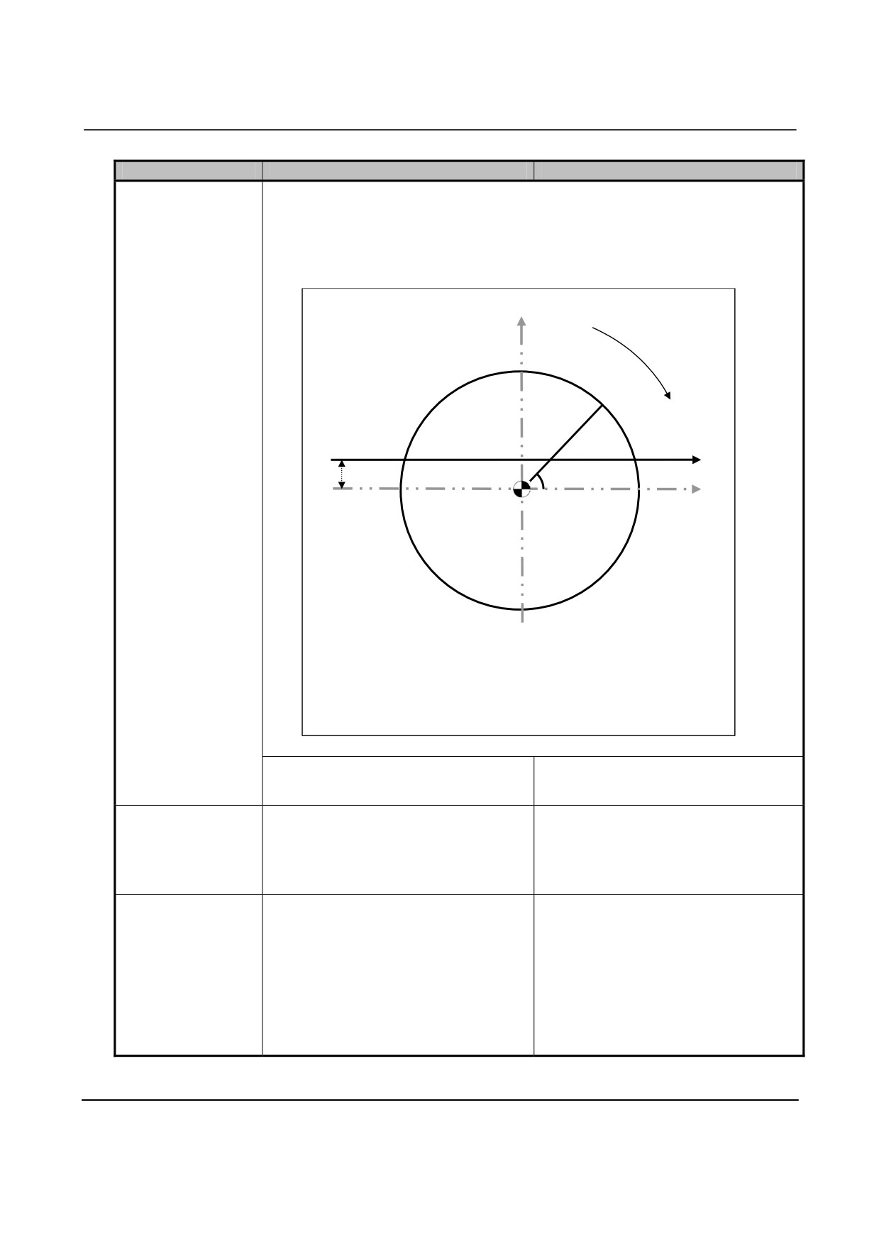
If the first axis of the plane is in a hypothetical axis direction relative to the center of
direction
the rotation axis, i.e. the center of the rotation axis is not on the X axis, the
compensation during
hypothetical axis direction compensation function in polar coordinate interpolation
polar coordinate
mode performs polar coordinate interpolation while taking the error into consideration.
interpolation
Set the error value in parameter No. 5464.
Hypothetical axis (C axis)
Rotation axis
(X,C)
X axis
Hypothetical axis direction error (P)
Center of the rotation axis
(X,C)
X-C plane point (The center of the rotation axis is the origin of
the X-C plane.)
X
X axis coordinate value in the X-C plane
C
Hypothetical axis coordinate value in the X-C plane
P
Hypothetical axis direction error
(Set the value in parameter No. 5464.)
-
This function is not available.
-
This function is available.
Maximum cutting
-
Set the value in parameter No. 5462.
-
Parameter No. 5462 is not available.
feedrate and feedrate
When the value is 0, the feedrate is
Set the value in parameter No. 1430.
clamp during polar
clamped by parameter No. 1422.
coordinate
interpolation
Automatic override
-
Enable or disable the function using bit
-
Bit 1 (AFC) of parameter No. 5450 is
and automatic
1 (AFC) of parameter No. 5450.
not available.
feedrate clamp during
Automatic override and automatic
polar coordinate
Bit 1 (AFC) of parameter No. 5450
feedrate clamp are always performed.
interpolation
In the polar coordinate interpolation mode,
automatic override and automatic feedrate
clamp are:
0: Not performed.
1: Performed.
B.40.2 Differences in Diagnosis Display
None.
- 512 -

B-64304EN-1/01
APPENDIX B.DIFFERENCES FROM SERIES 0i-C
B.41 PATH INTERFERENCE CHECK (2-PATH CONTROL)
B.41.1 Differences in Specifications
Function
Series 0i-C
Series 0i-D
Interference alarm
-
Bit 7 (BFA) of parameter No. 1300 is
-
Bit 7 (BFA) of parameter No. 1300 is
not supported.
supported.
Therefore, if an interference alarm
Setting 1 in BFA allows the tool to stop
occurs, the tool stops after entering the
before entering the prohibited area,
prohibited area.
thus eliminating the need to make the
This makes it necessary to make the
prohibited area slightly larger than
prohibited area slightly larger than
actually necessary.
actually necessary.
Bit 7 (BFA) of parameter No. 1300
If a stored stoke check 1, 2, or 3 alarm
occurs, if an interference alarm occurs with
the inter-path interference check function
(T series), or if an alarm occurs with
chuck/tail stock barrier (T series), the tool
stops:
0: After entering the prohibited area.
1: Before entering the prohibited area.
B.41.2 Differences in Diagnosis Display
None.
- 513 -

B.DIFFERENCES FROM SERIES 0i-C APPENDIX
B-64304EN-1/01
B.42 SYNCHRONOUS CONTROL AND COMPOSITE CONTROL
(2-PATH CONTROL)
B.42.1 Differences in Specifications
Function
Series 0i-TTC
Series 0i-D
Axis synchronous
-
Adding synchronous or composite
-
Adding synchronous or composite
control
control disables simple synchronous
control does not disable simple
(Series 0i-C: Quick
control.
synchronous control.
synchronous control)
-
The master and slave axes used for
axis synchronous control cannot be
used for synchronous control.
-
Composite control is available for the
master axis used for axis synchronous
control, while it is not available for the
slave axis.
Feed forward function
-
Make a selection using bit 1 (SVF) of
-
Bit 1 (SVF) of parameter No. 8165 is
and cutting/rapid
parameter No. 8165.
not available.
traverse change
The tool always behaves as when SVF
function for
Bit 1 (SVF) of parameter No. 8165
is set to 1.
synchronous and
In synchronous or composite control, the
(The feed forward function and
composite axes of
feed forward function and cutting/rapid
cutting/rapid traverse change function
another path
traverse change function for synchronous
are enabled for synchronous and
and composite axes of another path are:
composite axes of another path.)
0: Disabled.
1: Enabled.
Move command when
-
Not prohibited.
-
Make a selection using bit 7 (NUMx) of
neither synchronous
parameter No. 8163.
nor composite control
is in effect
Bit 7 (NUMx) of parameter No. 8163
When neither synchronous nor composite
control is in effect, specifying the move
command for an axis that is set with this
parameter is:
0: Not prohibited.
1: Prohibited.
(Alarm PS0353 is issued.)
- 514 -

B-64304EN-1/01
APPENDIX B.DIFFERENCES FROM SERIES 0i-C
Function
Series 0i-TTC
Series 0i-D
Behavior when an
-
Both paths are placed in the feed hold
-
Make a selection using bit 0 (MPA) of
alarm is issued in
state.
parameter No. 8168.
relation to
Bit 0 (MPA) of parameter No. 8168
synchronous or
If an alarm is issued in relation to
composite control
synchronous, composite, or superposition
control:
0: Both paths are placed in the feed hold
state.
1: Only the path including axes related to
synchronous, composite, or
superposition control is placed in the
feed hold state.
For example, when synchronous
control is exerted in one path, only the
path that caused the alarm is placed in
the feed hold state. The handling of
the other path depends on the setting
of bit 1 (IAL) of parameter No. 8100.
Behavior when
-
The synchronous or composite control
-
Make a selection using bit 5 (NCS) of
overtravel occurs for
mode is canceled.
parameter No. 8160.
an axis under
Bit 5 (NCSx) of parameter No. 8160
synchronous or
If overtravel occurs for an axis under
composite control
synchronous, composite, or superposition
control, the synchronous, composite, or
superposition control mode is:
0:
Canceled.
1:
Not canceled.
Switch between
-
The signals can be switched at any
-
Use an M code command. Specify a
synchronous control
time.
waiting M code (M code without
axis selection signal
buffering) before and after the M code.
and composite control
When synchronous or composite
axis selection signal
control is exerted in one path, specify
during automatic
an M or other code without buffering
operation
before and after the M code that starts
or cancels the control so as to prohibit
the look-ahead operation.
Synchronous control
Item
Series 0i-TTC
Series 0i-D
G28 when the master
-
When the reference position of the slave
-
When the reference position of the
axis is parking
axis is not established, the machine
slave axis is not established, alarm
coordinates are moved to the
PS0354 occurs.
coordinates set in parameter No. 1240,
completing the reference position return.
Update of the
-
Make a selection using bit 4 (SPN) of
-
Bit 4 (SPN) of parameter No. 8164 is
workpiece coordinates
parameter No. 8164.
not available.
and relative
Bit 4 (SPN) of parameter No. 8164
The tool always behaves as when
coordinates of the
The workpiece coordinates and relative
SPNx is set to 0 (coordinates are
slave axis under
coordinates of the slave axis under
updated).
synchronous control
synchronous control are:
0: Updated.
1: Not updated.
- 515 -

B.DIFFERENCES FROM SERIES 0i-C APPENDIX
B-64304EN-1/01
Item
Series 0i-TTC
Series 0i-D
Out-of-synchronizatio
-
Out-of-synchronization detection is not
-
Out-of-synchronization detection is
n detection when
performed.
performed.
synchronous control is
exerted in one path (1
is set in bit 1 (SER) of
parameter No. 8162)
Manual handle
-
Always reflected on the slave axis.
-
Select whether to reflect the amount or
interruption amount or
mode on the slave axis, using bit 5
mirror image mode for
(SMIx) of parameter No. 8163.
the master axis
Bit 5 (SMIx) of parameter No. 8163
During synchronous control, the manual
handle interruption amount or mirror
image mode for the master axis is:
0: Reflected on the slave axis.
1: Not reflected on the slave axis.
Automatic setting of a
-
A workpiece coordinate system is not
-
Make a selection using bit 6 (SPVx) of
workpiece coordinate
automatically set for the slave axis.
parameter No. 8167.
system for the slave
Bit 6 (SPVx) of parameter No. 8167
axis at the end of
At the end of synchronous control, a
synchronous control
workpiece coordinate system for the slave
axis is:
0: Not automatically set.
1: Automatically set.
The workpiece coordinate system to
be set is determined by the machine
coordinate values and the workpiece
coordinate values of the reference
points of the individual axes defined by
parameter No. 1250.
Composite control
Item
Series 0i-TTC
Series 0i-D
G28 during composite
-
When the reference position of the
-
When the reference position of the
control
composite axis of the other path is not
composite axis of the other path is not
established, the machine coordinates
established, alarm PS0359 occurs.
are moved to the coordinates set in
parameter No. 1240, completing the
reference position return.
Composite control for
-
Select whether to use the composite
-
Bit 1 (CZMx) of parameter No. 8161 is
the Cs contour axis
function of the Cs contour axis
not available.
reference position
reference position return command, by
The tool always behaves as when
return command when
using bit 1 (CZMx) of parameter No.
CZMx is set to 1 (composite control is
composite control is
8161.
used).
exerted for Cs contour
Bit 1 (CZMx) of parameter No. 8161
axes
When composite control is exerted for Cs
contour axes, the composite control
function for the Cs contour axis reference
position return command is:
0: Not used.
1: Used.
- 516 -

B-64304EN-1/01
APPENDIX B.DIFFERENCES FROM SERIES 0i-C
Item
Series 0i-TTC
Series 0i-D
Manual handle
-
Disabled.
-
Enable or disable the interruption using
interruption for
bit 6 (MMIx) of parameter No. 8163.
composite axes
Bit 6 (MMIx) of parameter No. 8163
During composite control, manual handle
interruption for composite axes is:
0:
Enabled.
1:
Disabled.
Current position
-
Make a selection using bit 0 (MDXx) of
-
Bit 0 (MDXx) of parameter No. 8163 is
display during
parameter No. 8163.
not available.
composite control
Bit 0 (MDXx) of parameter No. 8163.
The coordinate values of the local path
(absolute/relative
During composite control, the current
are always displayed.
coordinates)
position display (absolute/relative
coordinates) shows:
0: Coordinate values of the local path.
1: Coordinate values of the mate path.
G53 during composite
-
Make a selection using bit 2 (CPMx) of
-
Bit 2 (CPMx) of parameter No. 8165 is
control
parameter No. 8165.
not available.
Bit 2 (CPMx) of parameter No. 8165.
The tool always behaves as when
During composite control, machine
CPMx is set to 1.
coordinate system selection (G53) is:
(G53 is enabled.)
0: Disabled.
1: Enabled.
(The travel distance is calculated so that
the machine moves according to the
machine coordinate system selection
signal of the mate path.)
Constant
-
Make a selection using bit 0 (NLSx) of
-
Bit 0 (NLSx) of parameter No. 8167 is
acceleration/decelerati
parameter No. 8167.
not available.
on of acceleration
Bit 0 (NLSx) of parameter No. 8167
The tool always behaves as when
time for
Constant acceleration/deceleration of
NLSx is set to 1.
acceleration/decelerati
acceleration time for
(Constant acceleration/deceleration of
on in rapid traverse for
acceleration/deceleration in rapid traverse
acceleration time is enabled.)
an axis subject to
for an axis subject to composite control (bit
composite control (bit
4 (RPT) of parameter No. 1603) is:
4 (RPT) of parameter
0: Enabled.
No. 1603)
1: Disabled.
Machine coordinates
-
The coordinate values of the local path
-
Make a selection using bit 0 (MDMx) of
during composite
are displayed.
parameter No. 8169.
control
Bit 0 (MDMx) of parameter No. 8169
The machine coordinates displayed during
composite control are:
0: Coordinate values of the local path.
1: Machine coordinate values of the mate
path.
Reading of machine
-
The coordinate values of the local path
-
Make a selection using bit 1 (MVMx) of
coordinates (#5021
are read.
parameter No. 8169.
and later) during
Bit 1 (MVMx) of parameter No. 8169
composite control
The machine coordinates (#5021 and
later) that are read during composite
control are:
0: Machine coordinate values of the local
path.
1: Machine coordinate values of the mate
path.
- 517 -
B.DIFFERENCES FROM SERIES 0i-C APPENDIX
B-64304EN-1/01
Item
Series 0i-TTC
Series 0i-D
Rapid traverse
-
The rapid traverse feedrate of the
-
Make a selection using bit 2 (MRFx) of
feedrate during
specified axis is used.
parameter No. 8169.
composite control
Bit 2 (MRFx) of parameter No. 8169
The rapid traverse feedrate used during
composite control is:
0: Rapid traverse feedrate of the
specified axis.
1: Rapid traverse feedrate of the moving
axis.
B.42.2 Differences in Diagnosis Display
Item
Series 0i-TTC
Series 0i-D
Synchronization error
-
Displayed in parameter No. 8182.
-
Displayed in diagnosis No. 3502.
value display for each
axis
- 518 -

B-64304EN-1/01
APPENDIX B.DIFFERENCES FROM SERIES 0i-C
B.43 SUPERIMPOSED CONTROL (2-PATH CONTROL)
B.43.1 Differences in Specifications
Function
Series 0i-TTC
Series 0i-D
Axis synchronous
-
Adding superimposed control disables
-
Adding superimposed control does not
control
simple synchronous control.
disable simple synchronous control.
(Series 0i: Quick
-
The same axis can be used as the
synchronous control)
master axis for axis synchronous
control and the master axis for
superimposed control.
Feed hold when an
-
Both paths are placed in the feed hold
-
Make a selection using bit 0 (MPA) of
alarm occurs with
state.
parameter No. 8168.
respect to
Bit 0 (MPA) of parameter No. 8168
superimposed control
The axis movement in-progress signal
<Fn102> or axis movement direction signal
<Fn106> for the slave axis during
superimposed control:
0: Places both paths in the feed hold
state.
1: Places only the path including axes
related to superposition control in the
feed hold state.
(For example, when
superposition control is exerted in one
path, only the path that caused the
alarm is placed in the feed hold state.)
Reference position
-
Not available.
-
Not available.
return of the slave
Alarm PS0363 occurs.
axis during
superimposed control
Multiple slave axes
-
Superimposed control cannot be
-
Superimposed control can be exerted
exerted when there are multiple slave
when there are multiple slave axes and
axes and one master axis.
one master axis.
Axis movement
-
State output is performed according to
-
Make a selection using bit 4 (AXS) of
in-progress signal and
the result of adding superimposed
parameter No. 8160.
axis movement
move pulses.
Bit 4 (AXS) of parameter No. 8160
direction signal for the
The axis movement in-progress signal
slave axis during
<Fn102> or axis movement direction signal
superimposed control
<Fn106> for the slave axis during
superimposed control:
0: Performs state output according to the
result of adding superimposed move
pulses.
1: Performs state output according to the
result of moving the individual axes,
regardless of superimposed move
pulses.
- 519 -

B.DIFFERENCES FROM SERIES 0i-C APPENDIX
B-64304EN-1/01
Function
Series 0i-TTC
Series 0i-D
Axis overtravel during
-
The superimposed control mode is
-
Make a selection using bit 5 (NCS) of
superimposed control
canceled.
parameter No. 8160.
Bit 5 (NCS) of parameter No. 8160
If overtravel occurs for an axis under
synchronous, composite, or superposition
control, the synchronous, composite, or
superposition control mode is:
0: Canceled.
1: Not canceled.
Switch between
-
The signals can be switched at any
-
Use an M code command. Specify a
superimposed control
time.
Note that both the master and
waiting M code (M code without
axis selection signals
slave axes must be stopped.
buffering) before and after the M code.
during automatic
When superimposed control is exerted
operation
in one path, specify an M or other code
without buffering before and after the M
code that starts or cancels the control
so as to prohibit the look-ahead
operation.
B.43.2 Differences in Diagnosis Display
None.
- 520 -

B-64304EN-1/01
APPENDIX B.DIFFERENCES FROM SERIES 0i-C
B.44 Y AXIS OFFSET
B.44.1 Differences in Specifications
Function
Series 0i-C
Series 0i-D
Number of the axis for
-
Make a selection using bit 7 (Y03) of
-
Make a selection using parameter No.
which the Y axis offset
parameter No. 5004.
5043.
is used
When 0 or a value outside the data range
Bit 7 (Y03) of parameter No. 5004
is set, the Y axis offset is used for the Y
The Y axis offset is used for:
axes of the basic three axes (X, Y, and Z).
0:
4th axis.
1:
3rd axis.
B.44.2 Differences in Diagnosis Display
None.
- 521 -
B.DIFFERENCES FROM SERIES 0i-C APPENDIX
B-64304EN-1/01
B.45 CUTTER COMPENSATION/TOOL NOSE RADIUS
COMPENSATION
B.45.1 Differences in Specifications
Function
Series 0i-C
Series 0i-D
Cutter
-
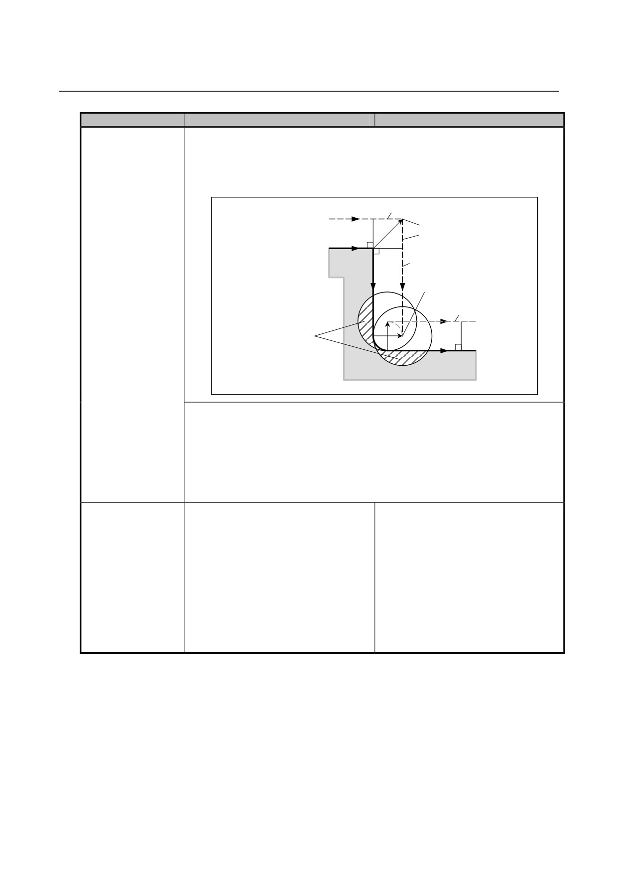
In Series 0i-D, the cutter compensation C (M series) and tool-nose radius
compensation/tool
compensation (T series) functions of Series 0i-C are collectively referred to as cutter
nose radius
compensation/tool nose radius compensation.
compensation
Corner circular
-
Not available.
-
Available.
interpolation (G39)
It is included in cutter
compensation/tool nose radius
compensation.
Since corner circular interpolation
(G39) is always enabled, bit 2 (G39) of
parameter No. 5008 is not available.
Cutter
-
Neither cutter compensation C nor tool
-
Cutter compensation/tool nose radius
compensation/tool
nose radius compensation is available
compensation is also available in MDI
nose radius
in MDI operation.
operation.
compensation in MDI
operation
Single block stop
-
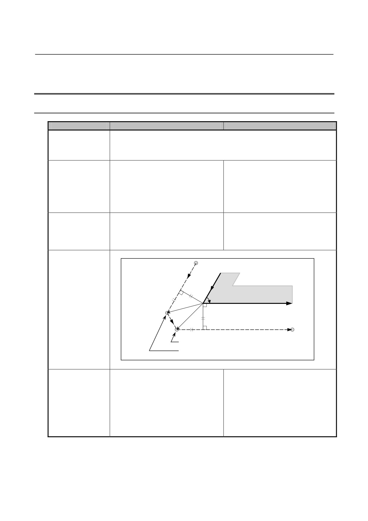
The single block stop position differs as shown below.
position during the
cutter
L
compensation/tool
nose radius
compensation mode
Workpiece
α
r
L
Programmed path
r
Cutter/tool nose radius
L
center path
L
L
Series 0i-D single block stop
Series 0i-C single block stop
Function to change
-
Not available.
-
At the start of or during the cutter
the compensation
compensation/tool nose radius
direction intentionally
compensation mode, specify I, J, or K
(IJ type vector, KI type
in a G00 or G01 block. This makes
vector, and JK type
the compensation vector at the end
vector)
point of the block perpendicular to the
direction specified by I, J, or K. This
way, you can change the compensation
direction intentionally.
- 522 -
B-64304EN-1/01
APPENDIX B.DIFFERENCES FROM SERIES 0i-C
Function
Series 0i-C
Series 0i-D
Stop position upon an
-
If the specified radius value for circular interpolation is smaller than that for cutter
overcutting alarm
compensation/tool nose radius compensation, as in the example below, performing
compensation inwardly through cutter compensation/tool nose radius compensation
causes overcutting, generating an alarm and stopping the tool. The stop position
differs.
N1
Cutter/tool nose radius
center path
P1
P
2
Programmed path
Workpiece
N2
P3
N3
Cutting as
programmed causes
[When single block stop occurs in the preceding block in Series 0i-C]
Since the tool moves until it reaches the end point of the block (P3 in the figure),
overcutting may result.
[When single block stop does not occur in the preceding block in Series 0i-C]
The tool stops immediately after executing the block (P2 in the figure).
[In the case of Series 0i-D]
Since the tool stops at the start point of the block (P1 in the figure), regardless of the
single block state, overcutting can be prevented.
Single block stop in a
-
Not available.
-
Depends on bit 0 (SBK) of parameter
block created
No. 5000.
internally for cutter
compensation/tool
Bit 0 (SBK) of parameter No. 5000
nose radius
In a block created internally for cutter
compensation
compensation/tool nose radius
compensation, single block stop is:
0: Not performed.
1: Performed.
This parameter is used to check a program
including cutter compensation/tool nose
radius compensation.
- 523 -