FANUC Series 0i-MODEL D, Series 0i Mate-MODEL D. For Lathe System USER’S MANUAL - page 12
6. MEMORY OPERATION
USING Series 10/11 FORMAT
PROGRAMMING
B-64304EN-1/01
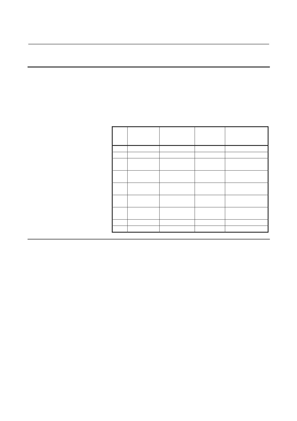
Relation with other functions
- Manual intervention
While a multiple repetitive canned cycle
(G70 to G76) is being
executed, it is possible to stop the cycle and to perform manual
intervention.
The setting of manual absolute on or off is effective for manual
operation.
- Interruption type macro
Any interruption type macro program cannot be executed during
execution of a multiple repetitive canned cycle.
- Program restart and tool retract and recover
These functions cannot be executed in a block in a multiple repetitive
canned cycle.
- Axis name and second auxiliary functions
Even if address U, V, W, or A is used as an axis name or second
auxiliary function, data specified at address U, V, W, or A in a G71 to
G73 or G76 block is assumed to be that for the multiple repetitive
canned cycle.
- Tool nose radius compensation
When using tool nose radius compensation, specify a tool nose radius
compensation command
(G41, G42) before a multiple repetitive
canned cycle command (G70, G71, G72, G73) and specify the cancel
command (G40) outside the blocks (from the block specified with P to
the block specified with Q) specifying a target finishing figure.
- 314 -
6.MEMORY OPERATION
B-64304EN-1/01
PROGRAMMING
USING Series 10/11 FORMAT
6.5
CANNED CYCLE FOR DRILLING
Canned cycles for drilling make it easier for the programmer to create
programs. With a canned cycle, a frequently-used machining
operation can be specified in a single block with a G function; without
canned cycles, more than one block is required. In addition, the use
of canned cycles can shorten the program to save memory.
Table 6.5 (a) lists canned cycles for drilling.
Table 6.5 (a) Canned cycles for drilling
Drilling
Operation in
Retraction
G
operation
the bottom hole
operation
Applications
code
(-Z direction)
position
(-Z direction)
G80
------
------
------
Canceling
G81
Cutting feed
------
Rapid traverse
Drilling, Spot drilling
Drilling, Counter
G82
Cutting feed
Dwell
Rapid traverse
boring
Cutting
G83
------
Rapid traverse
Peck drilling cycle
feed/intermittent
Cutting feed/
High-speed peck
G83.1
------
Rapid traverse
intermittent
drilling cycle
Dwell →
G84
Cutting feed
Cutting feed
Tapping
Spindle CCW
Dwell →
G84.2
Cutting feed
Cutting feed
Rigid tapping
Spindle CCW
G85
Cutting feed
------
Cutting feed
Boring
G89
Cutting feed
Dwell
Cutting feed
Boring
Explanation
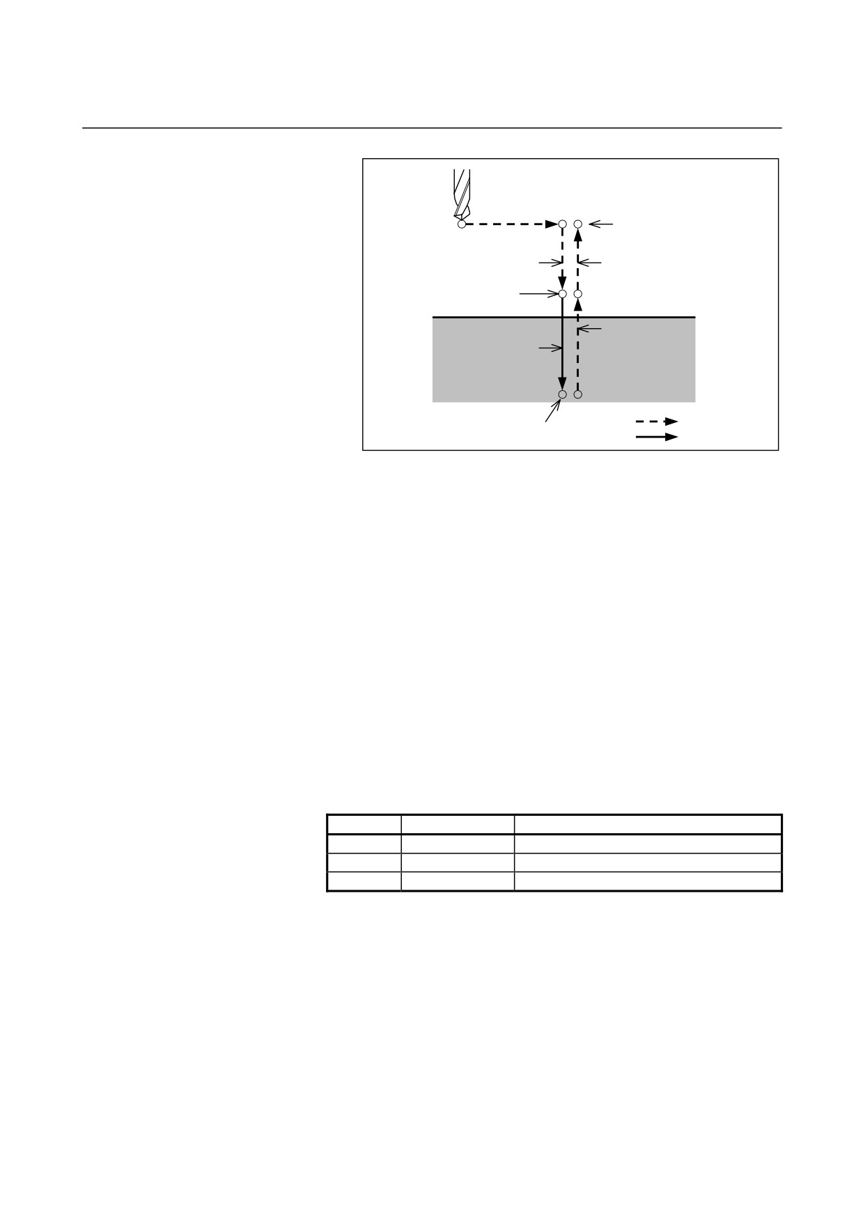
The canned cycle for drilling consists of the following six operation
sequences.
Operation 1
Positioning of X and Z axis (Another axis
may be targeted.)
Operation 2
Rapid traverse up to point R level
Operation 3
Hole machining
Operation 4
Operation at the bottom of a hole
Operation 5
Retraction to point R level
Operation 6
Rapid traverse up to the initial level
- 315 -
6. MEMORY OPERATION
USING Series 10/11 FORMAT
PROGRAMMING
B-64304EN-1/01
Operation 1
Initial level
Operation 2
Operation 6
Point R level
Operation 5
Operation 3
Rapid traverse
Operation 4
Feed
Fig. 6.5 (a) Operation sequence of canned cycle for drilling
- Positioning plane
A positioning plane is determined by plane selection with G17, G18,
and G19.
The axes other than the drilling axis are used as positioning axes.
- Drilling axis
Although canned cycles include tapping and boring cycles as well as
drilling cycles, in this chapter, only the term drilling will be used to
refer to operations implemented with canned cycles.
The basic axis (X, Y, or Z) that does not exist on the positioning plane
or its parallel axis is used as the drilling axis.
The axis address of the drilling axis specified in the same block as the
G codes (G81 to G89) determines whether a basic axis or one of
parallel axes is used as the drilling axis.
If the axis address of the drilling axis is not specified, the basic axis is
used as the drilling axis.
Table 6.5 (b) Positioning plane and drilling axis
G code
Positioning plane
Drilling axis
G17
Xp-Yp-plane
Zp
G18
Zp-Xp-plane
Yp
G19
Yp-Zp-plane
Xp
Xp : X axis or its parallel axis
Yp : Y axis or its parallel axis
Zp : Z axis or its parallel axis
- 316 -
6.MEMORY OPERATION
B-64304EN-1/01
PROGRAMMING
USING Series 10/11 FORMAT
- Example
Suppose parameter No. 1022 is set so that U, V, and W are the parallel
axes of X, Y, and Z, respectively.
G17 G81
Z _ _: Drilling axis is Z axis.
G17 G81
W _ _: Drilling axis is W axis.
G18 G81
Y _ _: Drilling axis is Y axis.
G18 G81
V _ _: Drilling axis is V axis.
G19 G81
X _ _: Drilling axis is X axis.
G19 G81
U _ _: Drilling axis is U axis.
G17, G18, and G19 may be specified in a block in which G73 to G89
are not present.
CAUTION
Before switching between drilling axes, cancel
canned cycles.
NOTE
The Z-axis can always be used as the drilling axis
by setting FXY (bit 0 of parameter No.5101). When
FXY is 0, the Z-axis is always used as the drilling
axis.
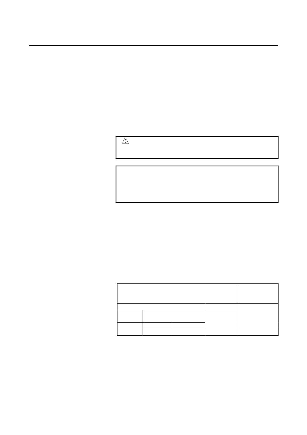
- Specification of point R
In the Series 0i command format, the distance from the initial level to
point R is specified using an incremental value during specification of
point R.
In the Series
10/11 command format, the specification method
depends on RAB (bit 6 of parameter No. 5102). When RAB = 0, an
incremental value is always used for specification. When RAB = 1 for
G code system A, an absolute value is used for specification. When
RAB = 1 for G code system B, C, an absolute value is used in G90
mode while an incremental value is used in G91 mode.
Series 0i
Series 10/11 command format
command
format
Parameter RAB (No.5102#6) = 1
RAB=0
G code
G code system B,C
system A
Incremental
Incremental
G90
G91
Absolute
Absolute
Incremental
- Diameter/radius programming
The diameter/radius specification of canned cycles for drilling R
command in the series 10/11 command format can be matched with
the diameter/radius specification of the drilling axis by setting RDI
(bit 7 of parameter No.5102) to 1.
- 317 -
6. MEMORY OPERATION
USING Series 10/11 FORMAT
PROGRAMMING
B-64304EN-1/01
- P
In the following G codes, dwell operation differs between Series
10/11 and Series 10/11.
Operation of this CNC using the Series 10/11 format
In G83, G83.1, G84, and G84.2, dwelling is performed only
when address P is specified in a block.
Operation of Series 10/11
In G83 and G83.1, dwelling is not performed.
In G84 and G84.2, dwelling with address P can be performed by
setting DWL (bit 1 of parameter No.6200). Address P is modal
data.
- Q
Address Q is always specified by using an incremental value during
specification of a radius.
- Feedrate for G85 and G89
In G85 and G89, the feedrate from point Z to point R is double the
cutting feedrate. For Series
10/11, it is the same as the cutting
feedrate.
- Drilling mode
G81 to G89 are modal G codes and remain in effect until canceled.
When in effect, the current state is the drilling mode.
Once drilling data is specified in the drilling mode, the data is retained
until modified or canceled.
Specify all necessary drilling data at the beginning of canned cycles;
when canned cycles are being performed, specify data modifications
only.
- 318 -
6.MEMORY OPERATION
B-64304EN-1/01
PROGRAMMING
USING Series 10/11 FORMAT
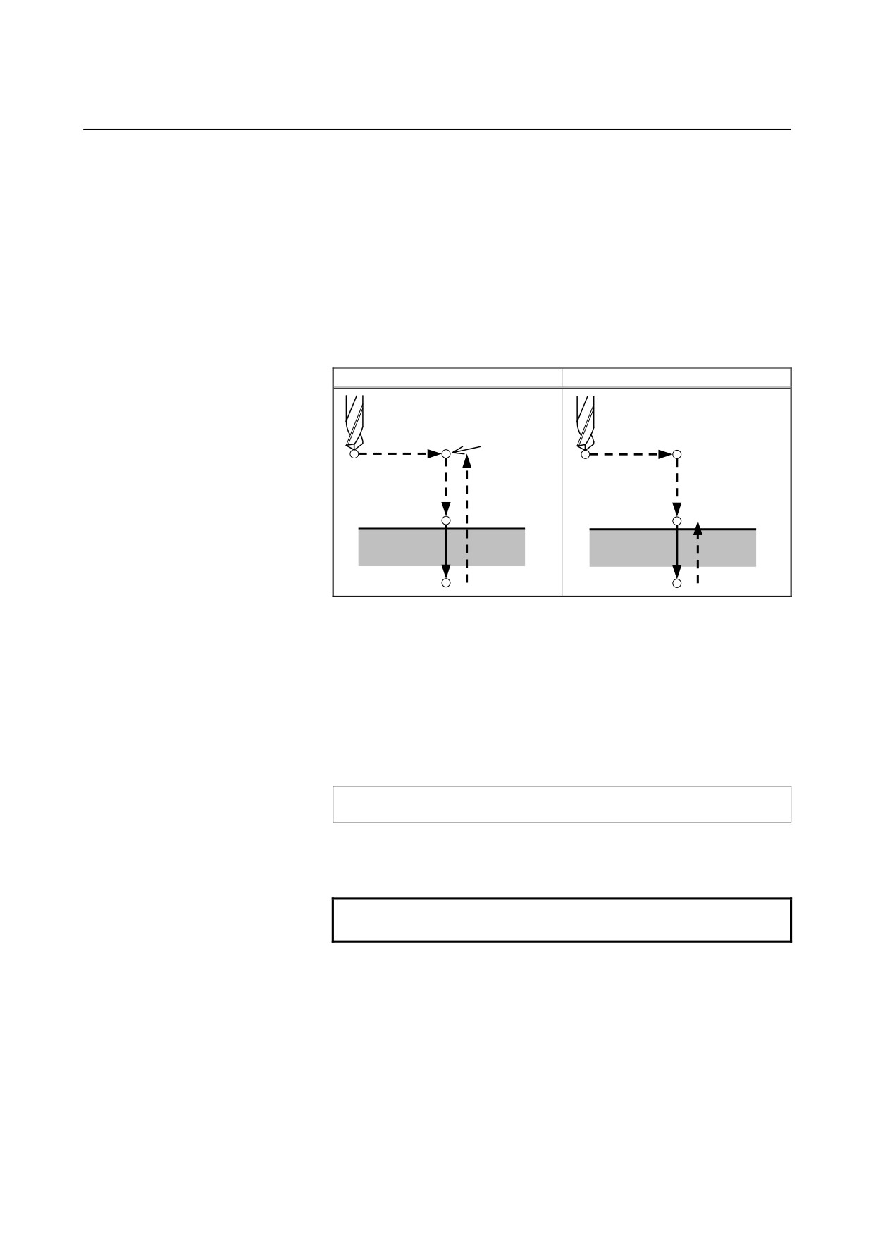
- Return point level G98/G99
In G code system A, the tool returns to the initial level from the
bottom of a hole. In G code system B or C, specifying G98 returns
the tool to the initial level from the bottom of a hole and specifying
G99 returns the tool to the point-R level from the bottom of a hole.
The following illustrates how the tool moves when G98 or G99 is
specified. Generally, G99 is used for the first drilling operation and
G98 is used for the last drilling operation.
The initial level does not change even when drilling is performed in
the G99 mode.
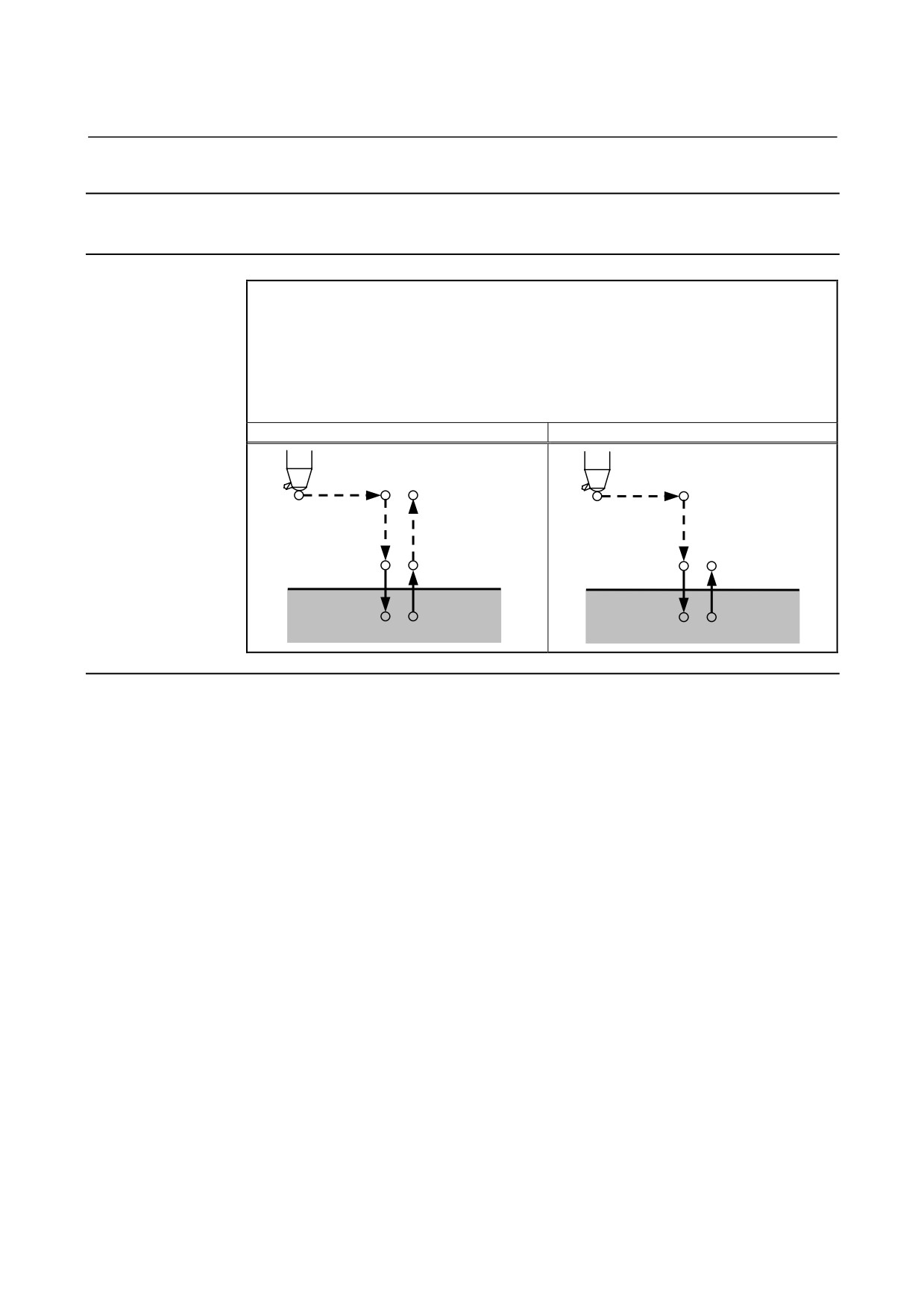
G98 (Return to initial level)
G99 (Return to point R level)
Initial level
Point R level
Fig. 6.5 (b) Initial level and point R level
- Number of repeats
To repeat drilling for equally-spaced holes, specify the number of
repeats in L_.
L is effective only within the block where it is specified.
Specify the first hole position in incremental mode.
If it is specified in absolute mode, drilling is repeated at the same
position.
Number of repeats L
The maximum command value = 9999
When L0 is specified, drilling data is just stored without drilling being
performed.
NOTE
For L, specify an integer of 0 or 1 to 9999.
- C axis clamp
The M code for C axis clamp can be specified in the Series 0i
command format, but it cannot be specified in the Series
10/11
command format.
- 319 -
6. MEMORY OPERATION
USING Series 10/11 FORMAT
PROGRAMMING
B-64304EN-1/01
- Disabling the Series 10/11 format
The Series 10/11 command format can be disabled only during a
canned cycle for drilling by setting F0C (bit 3 of parameter No.5102)
to 1. However, the repetitive count must be specified by address L.
CAUTION
If F16 (bit 3 of parameter No.5102) is set to 1, the
settings of RAB (bit 6 of No.5102) and RDI (bit 7 of
No.5102) are disabled, and operation when RAB=0
and RDI=0 is performed.
- Cancel
To cancel a canned cycle, use G80 or a group 01 G code.
Group 01 G codes (Example)
G00 : Positioning (rapid traverse)
G01 : Linear interpolation
G02 : Circular interpolation (CW) or helical interpolation (CW)
G03 : Circular interpolation (CCW) or helical interpolation (CCW)
- Symbols in figures
Subsequent subsections explain the individual canned cycles.
Figures in these explanations use the following symbols:
Positioning (rapid traverse G00)
Cutting feed (linear interpolation G01)
P
Dwell
- 320 -
6.MEMORY OPERATION
B-64304EN-1/01
PROGRAMMING
USING Series 10/11 FORMAT
6.5.1
Drilling Cycle, Spot Drilling Cycle (G81)
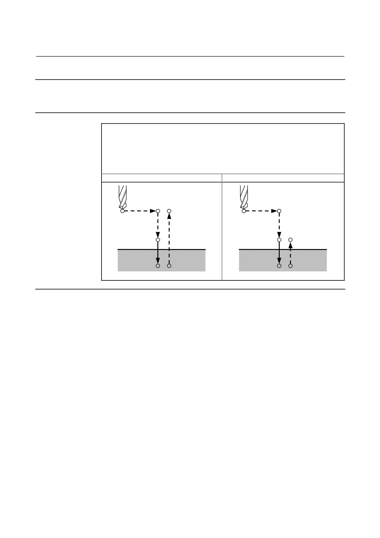
The normal drilling cycle is used. The tool is then retracted from the
bottom of the hole in rapid traverse.
Format
G81 X_ Y_ Z_ R_ F_ L_ ;
X_ Y_ : Hole position data
Z_
: The distance from point R to the bottom of the hole
R_
: The distance from the initial level to point R level
F_
: Cutting feedrate
L_
: Number of repeats (When it is needed.)
G81 (G98 mode)
G81 (G99 mode)
Initial level
Point R level
Point R
Point R
Point Z
Point Z
Explanation
- Operations
Rapid traverse to the point R level is performed after positioning of
the X- and Y- axes.
Then, drilling is performed from point R level to point Z.
Escaping moves in rapid traverse.
- Spindle rotation
Before specifying G81, use an auxiliary function (M code) to rotate
the spindle.
- Auxiliary function
If the G81 command and an M code are specified in the same block,
the M code is executed at the first positioning. When repetitive count
L is specified, the operation above is performed for the first time and
the M code is not performed second and later times.
- 321 -
6. MEMORY OPERATION
USING Series 10/11 FORMAT
PROGRAMMING
B-64304EN-1/01
Limitation
- Axis switching
Before switching between drilling axes, cancel canned cycles for
drilling.
- Drilling
In a block that does not include X, Y, Z, R, or an additional axis,
drilling is not performed.
- Cancel
The G codes (G00 to G03) in group 01 must not be specified in the
block in which G81 is specified. This cancels G81.
- 322 -
6.MEMORY OPERATION
B-64304EN-1/01
PROGRAMMING
USING Series 10/11 FORMAT
6.5.2
Drilling Cycle, Counter Boring (G82)
The normal drilling cycle is used. Cutting feed is performed to the
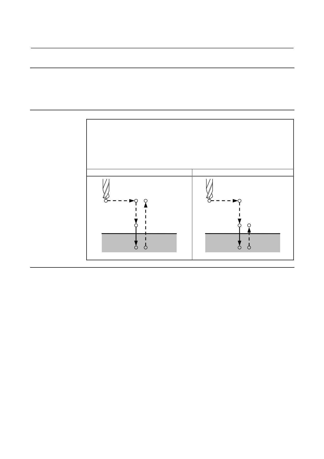
bottom of the hole, dwelling is performed at the bottom, and then
escaping from the bottom is performed in rapid traverse.
The accuracy of the hole depth is improved.
Format
G82 X_ Y_ Z_ R_ P_ F_ L_ ;
X_ Y_ : Hole position data
Z_
: The distance from point R to the bottom of the hole
R_
: The distance from the initial level to point R level
P_
: Dwell time at the bottom of a hole
F_
: Cutting feedrate
L_
: Number of repeats (When it is needed.)
G81 (G98 mode)
G81 (G99 mode)
Initial level
Point R level
Point R
Point R
Point Z
Point Z
P
P
Explanation
- Operations
Rapid traverse to the point R level is performed after positioning of
the X- and Y- axes.
Then, drilling is performed from point R level to point Z.
Dwelling is performed at the bottom of the hole and then escaping is
performed in rapid traverse.
- Spindle rotation
Before specifying G82, use an auxiliary function (M code) to rotate
the spindle.
- Auxiliary function
If the G82 command and an M code are specified in the same block,
the M code is executed at the first positioning. When repetitive count
L is specified, the operation above is performed for the first time and
the M code is not performed second and later times.
- 323 -
6. MEMORY OPERATION
USING Series 10/11 FORMAT
PROGRAMMING
B-64304EN-1/01
Limitation
- Axis switching
Before switching between drilling axes, cancel canned cycles for
drilling.
- Drilling
In a block that does not include X, Y, Z, R, or an additional axis,
drilling is not performed.
- P
P must be specified in a block in which drilling is instructed.
Otherwise, data is not stored as modal data.
- Cancel
The G codes (G00 to G03) in group 01 must not be specified in the
block in which G82 is specified. This cancels G82.
- 324 -
6.MEMORY OPERATION
B-64304EN-1/01
PROGRAMMING
USING Series 10/11 FORMAT
6.5.3
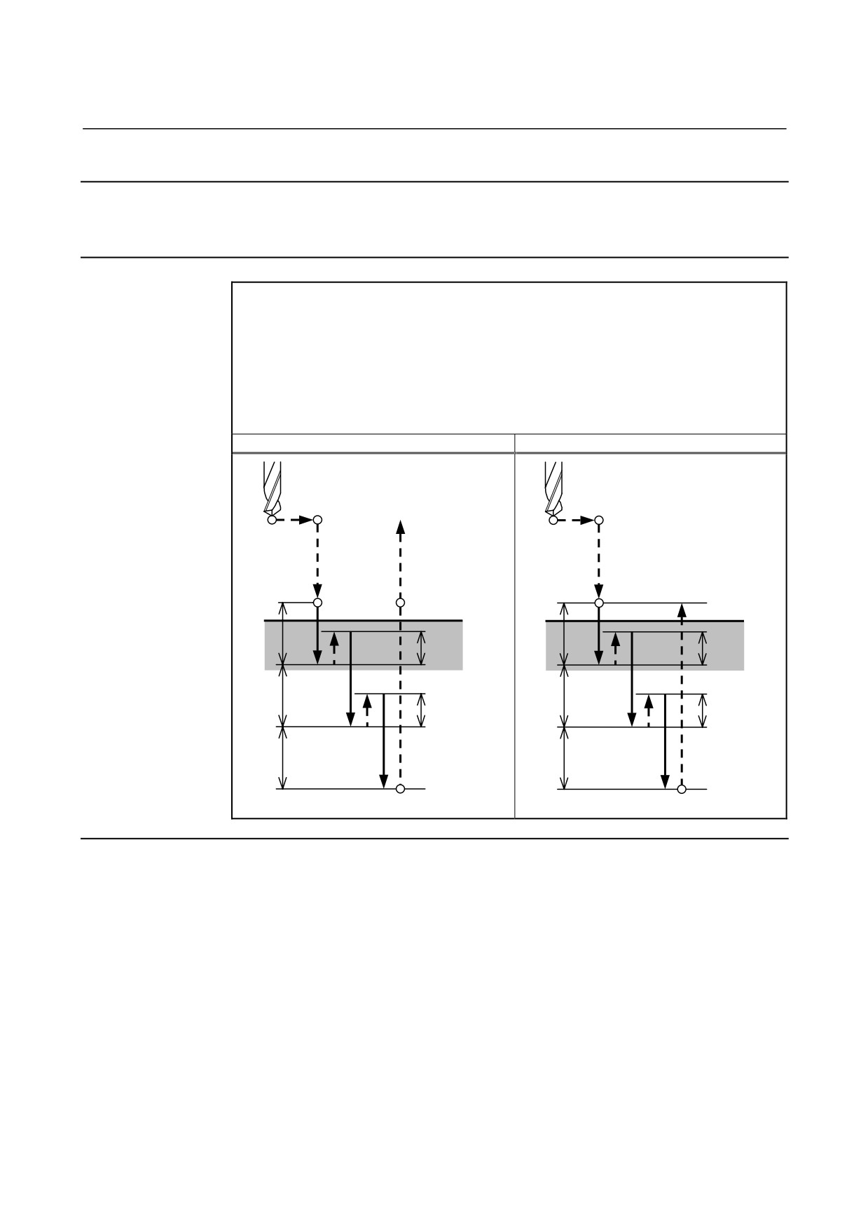
Peck Drilling Cycle (G83)
Peck drilling is performed.
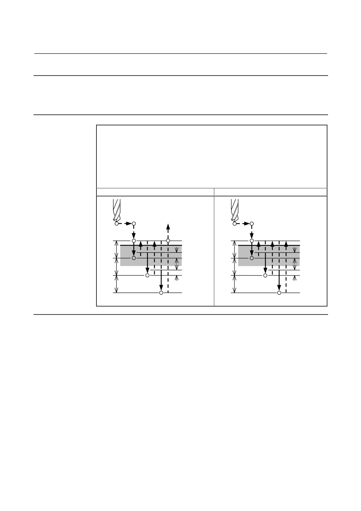
Cutting feed is performed intermittently to the bottom of the hole
while chips are discharged.
Format
G83 X_ Y_ Z_ R_ P_ Q_ F_ L_ ;
X_ Y_ : Hole position data
Z_
: The distance from point R to the bottom of the hole
R_
: The distance from the initial level to point R level
P_
: Dwell time
Q_
: Depth of cut for each cutting feed
F_
: Cutting feedrate
L_
: Number of repeats (When it is needed.)
G83 (G98 mode)
G83 (G99 mode)
Initial level
Point R level
Point R
Point R
q
q
d
d
q
q
d
d
q
q
Point Z
Point Z
P
P
Explanation
- Operations
Q indicates the depth of cut for each operation and is specified by an
incremental value.
In the second and later cutting operations, rapid traverse is changed to
cutting feed at the point distance "d" back from the previously drilled
position. "d" is set in parameter No. 5115.
A positive value must be specified for Q. A negative value is
ignored.
- Spindle rotation
Before specifying G83, use an auxiliary function (M code) to rotate
the spindle.
- Auxiliary function
If the G83 command and an M code are specified in the same block,
the M code is executed at the first positioning. When repetitive count
L is specified, the operation above is performed for the first time and
the M code is not performed second and later times.
- 325 -
6. MEMORY OPERATION
USING Series 10/11 FORMAT
PROGRAMMING
B-64304EN-1/01
Limitation
- Axis switching
Before switching between drilling axes, cancel canned cycles for
drilling.
- Drilling
In a block that does not include X, Y, Z, R, or an additional axis,
drilling is not performed.
- P
Dwelling is performed only when address P is specified in a block.
- Q
Q must be specified in a block in which drilling is instructed.
Otherwise, data is not stored as modal data.
- Cancel
The G codes (G00 to G03) in group 01 must not be specified in the
block in which G83 is specified. This cancels G83.
- 326 -
6.MEMORY OPERATION
B-64304EN-1/01
PROGRAMMING
USING Series 10/11 FORMAT
6.5.4
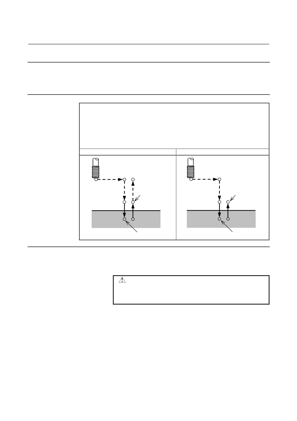
High-speed Peck Drilling Cycle (G83.1)
This cycle performs high-speed peck drilling. It performs cutting feed
intermittently while discharging chips.
Format
G83.1 X_ Y_ Z_ R_ P_ Q_ F_ L_ ;
X_ Y_ : Hole position data
Z_
: The distance from point R to the bottom of the hole
R_
: The distance from the initial level to point R level
P_
: Dwell time
Q_
: Depth of cut for each cutting feed
F_
: Cutting feedrate
L_
: Number of repeats (When it is needed)
G83.1 (G98 mode)
G83.1 (G99 mode)
Initial level
Point R
Point R
Point R level
q
q
d
d
q
q
d
d
q
q
Point Z
Point Z
P
P
Explanation
- Operations
Since intermittent feed in the Z-axis direction makes discharge of
chips easier and allows the fine setting of the escaping amount,
efficient machining can be performed.
Escape amount d is set in parameter No. 5114.
Escaping moves in rapid traverse.
- Spindle rotation
Before specifying G83.1, use an auxiliary function (M code) to rotate
the spindle.
- 327 -
6. MEMORY OPERATION
USING Series 10/11 FORMAT
PROGRAMMING
B-64304EN-1/01
- Auxiliary function
If the G83.1 command and an M code are specified in the same block,
the M code is executed at the first positioning. When repetitive count
L is specified, the operation above is performed for the first time and
the M code is not performed second and later times.
Limitation
- Axis switching
Before switching between drilling axes, cancel canned cycles for
drilling.
- Drilling
In a block that does not include X, Y, Z, R, or an additional axis,
drilling is not performed.
- P
Dwelling is performed only when address P is specified in a block.
- Q
Q must be specified in a block in which drilling is instructed.
Otherwise, data is not stored as modal data.
- Cancel
The G codes (G00 to G03) in group 01 must not be specified in the
block in which G83.1 is specified. This cancels G83.1.
- 328 -
6.MEMORY OPERATION
B-64304EN-1/01
PROGRAMMING
USING Series 10/11 FORMAT
6.5.5
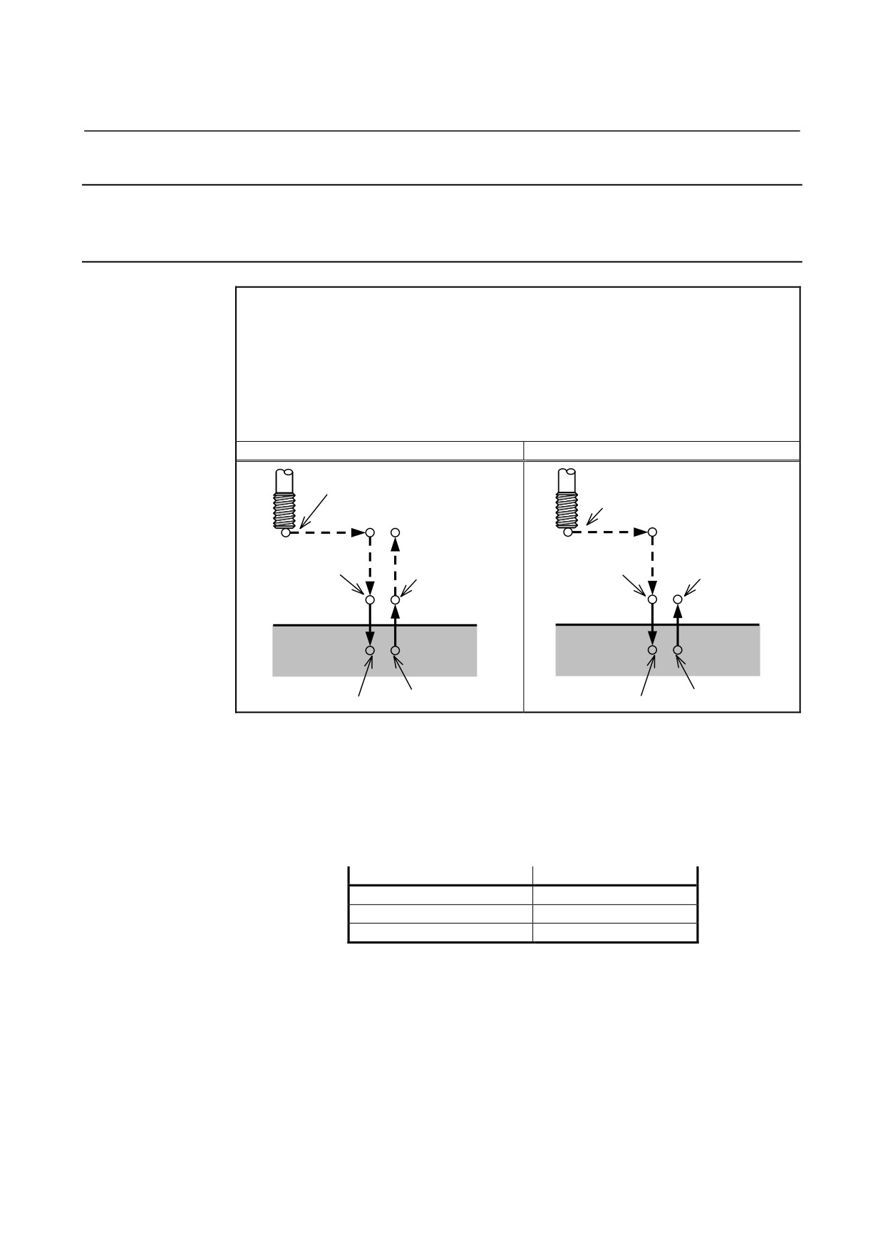
Tapping Cycle (G84)
This cycle performs tapping.
In this tapping cycle, when the bottom of the hole has been reached,
the spindle is rotated in the reverse direction.
Format
G84 X_ Y_ Z_ R_ P_ F_ L_ ;
X_ Y_ : Hole position data
Z_
: The distance from point R to the bottom of the hole
R_
: The distance from the initial level to point R level
P_
: Dwell time
F_
: Cutting feedrate
L_
: Number of repeats (When it is needed.)
G84 (G98 mode)
G84 (G99 mode)
Initial level
Spindle CW
Spindle CW
Point R
Point R
Point R level
Point Z
P
Point Z
P
Spindle CCW
Spindle CCW
Explanation
- Operations
Tapping is performed by rotating the spindle clockwise.
CAUTION
Feedrate override is ignored during tapping. In
addition, applying feed hold does not stop the
machine until return operation is completed.
- Spindle rotation
Before specifying G84, use an auxiliary function (M code) to rotate
the spindle.
When drilling in which the distance from the hole position and initial
level to the point R level is short is continuously performed, the
spindle may not reach the normal speed by the time cutting operation
for the hole is ready to be performed. In this case, reserve a time by
inserting dwelling by G04 before each drilling operation without
specifying repetitive count L.
Since this consideration may not be required depending on the
machine type, refer to the manual issued by the machine tool builder.
- 329 -
6. MEMORY OPERATION
USING Series 10/11 FORMAT
PROGRAMMING
B-64304EN-1/01
- Auxiliary function
If the G84 command and an M code are specified in the same block,
the M code is executed at the first positioning. When repetitive count
L is specified, the operation above is performed for the first time and
the M code is not performed second and later times.
Limitation
- Axis switching
Before switching between drilling axes, cancel canned cycles for
drilling.
- Drilling
In a block that does not include X, Y, Z, R, or an additional axis,
drilling is not performed.
- P
Dwelling is performed only when address P is specified in a block.
- Cancel
The G codes (G00 to G03) in group 01 must not be specified in the
block in which G84 is specified. This cancels G84.
NOTE
Set M5T (bit 6 of parameter No. 5101) to specify
whether the spindle stop command (M05) is
specified before the command for rotating the
spindle in the forward or reverse direction (M03 or
M04) is specified.
For details, refer to the manual issued by the
machine tool builder.
- 330 -
6.MEMORY OPERATION
B-64304EN-1/01
PROGRAMMING
USING Series 10/11 FORMAT
6.5.6
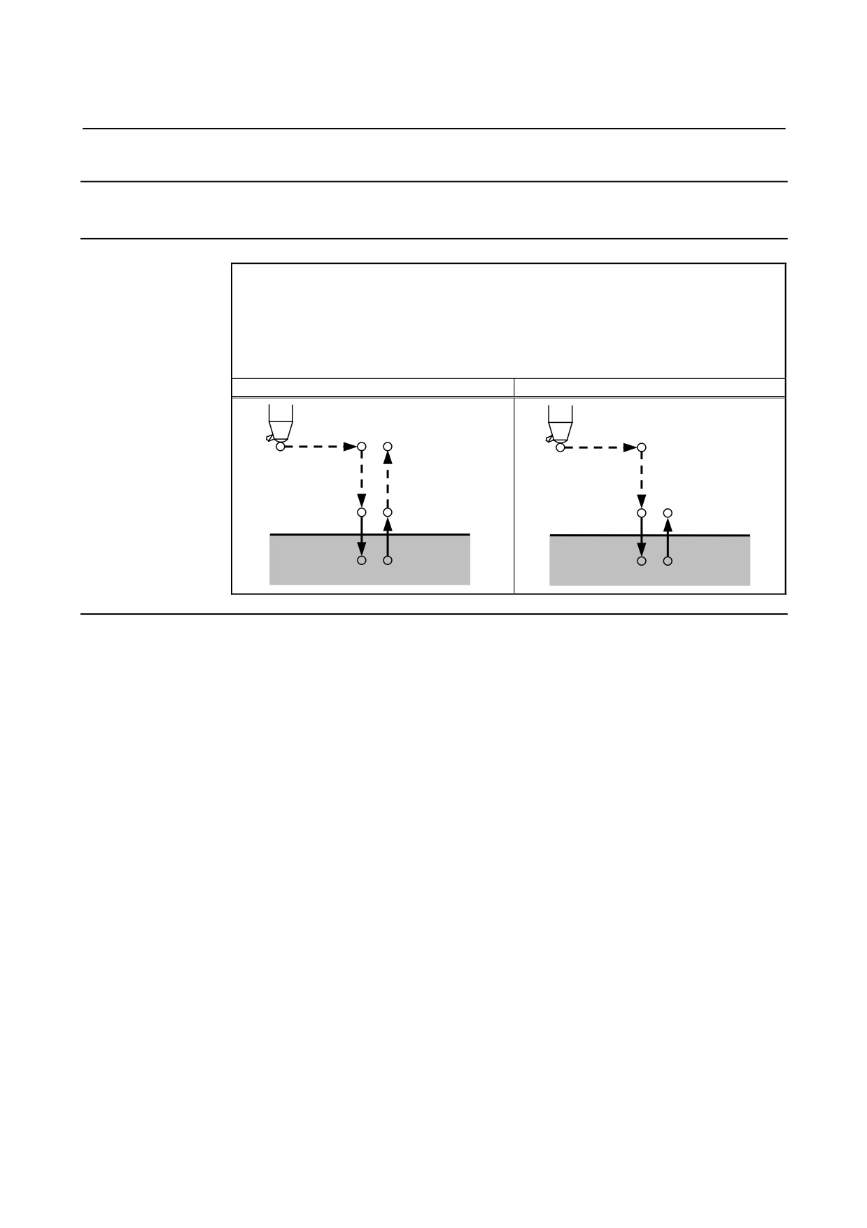
Tapping Cycle (G84.2)
Controlling the spindle motor in the same way as a servo motor
executes the high-speed tapping cycle.
Format
G84.2 X_ Y_ Z_ R_ P_ F_ L_ S_ ;
X_ Y_ : Hole position data
Z_
: The distance from point R to the bottom of the hole
R_
: The distance from the initial level to point R level
P_
: Dwell time
F_
: Cutting feedrate
L_
: Number of repeats (When it is needed.)
S_
: Spindle speed
G84.2 (G98 mode)
G84.2 (G99 mode)
Spindle stop
Spindle stop
Initial level
Spindle CW
Spindle stop
Spindle CW
Spindle stop
Point R
Point R
Point R level
Point Z
P
Point Z
P
Spindle stop
Spindle CCW
Spindle stop
Spindle CCW
A G code cannot discriminate between the front face tapping cycle
and side face tapping cycle using Series 10/11 format commands.
The drilling axis is determined by plane selection (G17, G18, or G19).
Specify the plane selection that becomes equivalent to the front face
tapping cycle or side face tapping cycle as appropriate.
(When bit 0
(FXY) of parameter No. 5101 is set to 0, the Z-axis is used as the
drilling axis. When the bit is set to 1, place selection is as follows.)
Plane selection
Drilling axis
G17 Xp-Yp plane
Zp
G18 Zp-Xp plane
Yp
G19 Yp-Zp plane
Xp
Xp: X-axis or an axis parallel to it
Yp: Y-axis or an axis parallel to it
Zp: Z-axis or an axis parallel to it
- 331 -
6. MEMORY OPERATION
USING Series 10/11 FORMAT
PROGRAMMING
B-64304EN-1/01
Explanation
- Operations
The tool is positioned along the X- and Y-axes, then moves to the
point R level in rapid traverse.
Tapping is performed from the point R level to point Z, after which
the spindle stops and the tool dwells. Then, the spindle starts reverse
rotation, the tool is retracted to the point R level, and the spindle stops.
After that, when G98 is specified, the tool moves to the initial level in
rapid traverse.
During tapping, the feedrate override and spindle override are
assumed to be 100%. For retraction (operation 5), however, a fixed
override of up to 2000% can be applied by setting bit 4 (DOV) of
parameter No.
5200, bit
3
(OVU) of parameter No.
5201, and
parameter No. 5211.
- Thread lead
In the feed per minute mode, feedrate ÷ spindle speed = thread lead.
In the feed per rotation mode, feedrate = thread lead.
Limitation
- Axis switching
Before switching between drilling axes, cancel canned cycles for
drilling. If the drilling axis is changed in the rigid mode, alarm
PS0206 is issued.
- Drilling
In a block that does not include X, Y, Z, R, or an additional axis,
drilling is not performed.
- P
Dwelling is performed only when address P is specified in a block.
- Cancel
The G codes (G00 to G03) in group 01 must not be specified in the
block in which G84.2 is specified. This cancels G84.2.
- Tool offset
In the canned cycle mode, tool offsets are ignored.
- 332 -
6.MEMORY OPERATION
B-64304EN-1/01
PROGRAMMING
USING Series 10/11 FORMAT
6.5.7
Boring Cycle (G85)
This cycle is used to bore a hole.
Format
G85 X_ Y_ Z_ R_ F_ L_ ;
X_ Y_ : Hole position data
Z_
: The distance from point R to the bottom of the hole
R_
: The distance from the initial level to point R level
F_
: Cutting feedrate
L_
: Number of repeats (When it is needed.)
G85 (G98 mode)
G85 (G99 mode)
Initial level
Point R level
Point R
Point R
Point Z
Point Z
Explanation
- Operations
Rapid traverse to the point R level is performed after positioning of
the X- and Y- axes.
Then, drilling is performed from point R level to point Z.
After reaching point Z, return to point R in cutting feed.
- Spindle rotation
Before specifying G85, use an auxiliary function (M code) to rotate
the spindle.
- Auxiliary function
If the G85 command and an M code are specified in the same block,
the M code is executed at the first positioning. When repetitive count
L is specified, the operation above is performed for the first time and
the M code is not performed second and later times.
- 333 -
6. MEMORY OPERATION
USING Series 10/11 FORMAT
PROGRAMMING
B-64304EN-1/01
Limitation
- Axis switching
Before switching between drilling axes, cancel canned cycles for
drilling.
- Drilling
In a block that does not include X, Y, Z, R, or an additional axis,
drilling is not performed.
- Cancel
The G codes (G00 to G03) in group 01 must not be specified in the
block in which G85 is specified. This cancels G85.
- 334 -
6.MEMORY OPERATION
B-64304EN-1/01
PROGRAMMING
USING Series 10/11 FORMAT
6.5.8
Boring Cycle (G89)
This cycle is used to bore a hole.
Format
G89 X_ Y_ Z_ R_ P_ F_ L_ ;
X_ Y_ : Hole position data
Z_
: The distance from point R to the bottom of the hole
R_
: The distance from the initial level to point R level
P_
: Dwell time at the bottom of a hole
F_
: Cutting feedrate
L_
: Number of repeats (When it is needed.)
G89 (G98 mode)
G89 (G99 mode)
Initial level
Point R level
Point R
Point R
Point Z
Point Z
P
P
Explanation
- Operations
This is the same as G85, but dwelling is performed at the bottom of
the hole.
- Spindle rotation
Before specifying G89, use an auxiliary function (M code) to rotate
the spindle.
- Auxiliary function
If the G89 command and an M code are specified in the same block,
the M code is executed at the first positioning. When repetitive count
L is specified, the operation above is performed for the first time and
the M code is not performed second and later times.
- 335 -
6. MEMORY OPERATION
USING Series 10/11 FORMAT
PROGRAMMING
B-64304EN-1/01
Limitation
- Axis switching
Before switching between drilling axes, cancel canned cycles for
drilling.
- Drilling
In a block that does not include X, Y, Z, R, or an additional axis,
drilling is not performed.
- P
P must be specified in a block in which drilling is instructed.
Otherwise, data is not stored as modal data.
- Cancel
The G codes (G00 to G03) in group 01 must not be specified in the
block in which G89 is specified. This cancels G89.
- 336 -

6.MEMORY OPERATION
B-64304EN-1/01
PROGRAMMING
USING Series 10/11 FORMAT
6.5.9
Canned Cycle for Drilling Cancel (G80)
G80 cancels canned cycle for drilling.
Format
G80 ;
Explanation
Canned cycle for drilling is canceled to perform normal operation.
Point R and point Z are cleared.
Other drilling data is also canceled (cleared).
6.5.10 Precautions to be Taken by Operator
- Reset and emergency stop
Even when the controller is stopped by resetting or emergency stop in
the course of drilling cycle, the drilling mode and drilling data are
saved ; with this mind, therefore, restart operation.
- Single block
When drilling cycle is performed with a single block, the operation
stops at the end points of operations 1, 2, 6 in Fig. 6.5 (a).
Consequently, it follows that operation is started up 3 times to drill
one hole. The operation stops at the end points of operations 1, 2
with the feed hold lamp ON. If there is a remaining repetitive count
at the end of operation 6, the operation is stopped by feed hold. If
there is no remaining repetitive count, the operation is stopped in the
single block stop state.
- Feed hold
When "Feed Hold" is applied between operations 3 and 5 by G84/G88,
the feed hold lamp lights up immediately if the feed hold is applied
again to operation 6.
- Override
During operation with G84 and G88, the feedrate override is 100%.
- 337 -
7.AXIS CONTROL FUNCTIONS
PROGRAMMING
B-64304EN-1/01
7
AXIS CONTROL FUNCTIONS
Chapter
7, "AXIS CONTROL FUNCTIONS", consists of the
following sections:
7.1
POLYGON TURNING (G50.2, G51.2)
339
7.2
SYNCHRONOUS, COMPOSITE AND SUPERIMPOSED
CONTROL BY PROGRAM COMMAND (G50.4, G51.4,
G50.5, G51.5, G50.6, AND G51.6)
345
- 338 -
B-64304EN-1/01
PROGRAMMING
7.AXIS CONTROL FUNCTIONS
7.1
POLYGON TURNING (G50.2, G51.2)
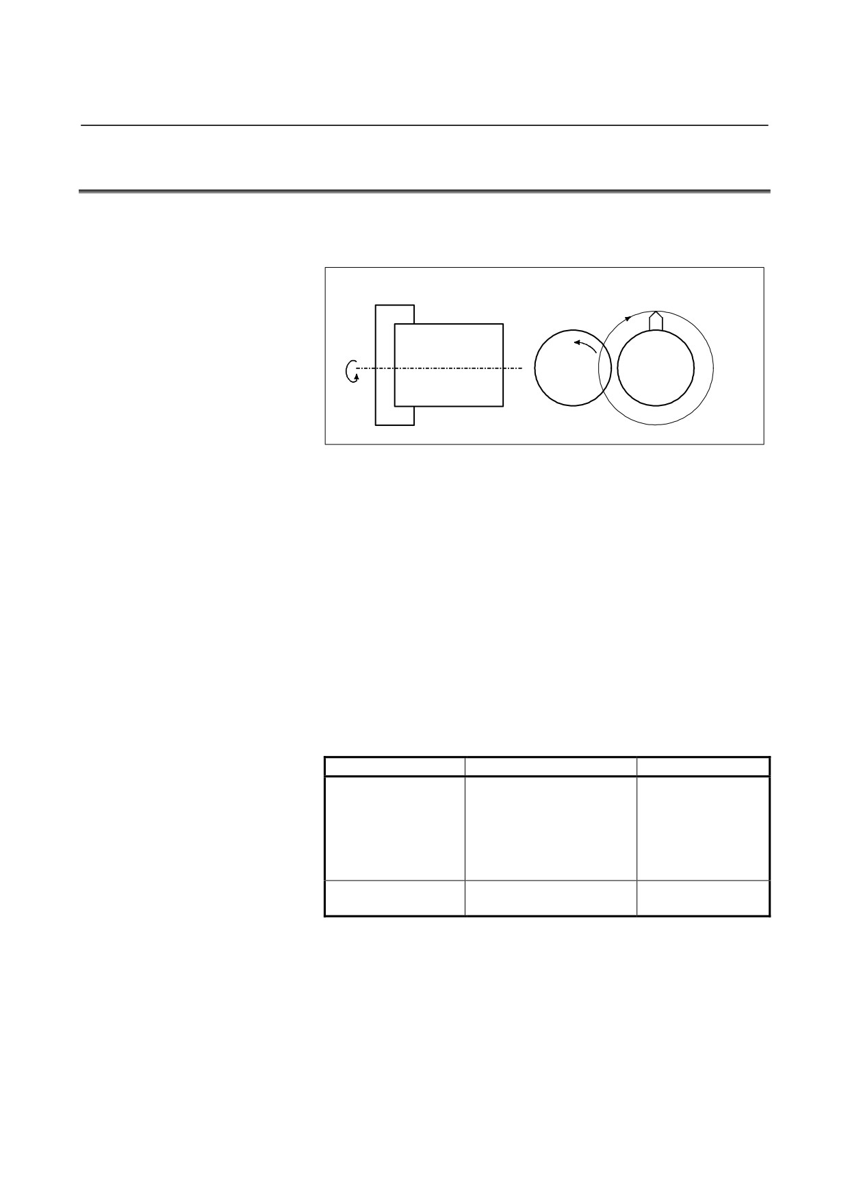
Polygon turning means machining a workpiece to a polygonal figure
by rotating the workpiece and tool at a certain ratio.
W orkpiece
W orkpiece
Tool
Fig. 7.1 (a) Polygon turning
By changing conditions which are rotation ratio of workpiece and tool
and number of cutters, the workpiece can be machined to a square or
hexagon. The machining time can be reduced as compared with
polygonal figure machining using the polar coordinate interpolation.
The machined figure, however, is not exactly polygonal. Generally,
polygon turning is used for the heads of square and/or hexagon bolts
or hexagon nuts.
As the tool rotary axis, one of the following can be used:
•
CNC controlled axis (servo axis)
•
Second spindle (Two serial spindles are connected.)
Polygonal machining performed using a servo axis as the tool rotary
axis is referred to as polygon turning.
Polygonal machining
performed using the second spindle as the tool rotary axis is referred
to as polygon turning with two spindles.
Function name
Workpiece axis
Tool rotary axis
Spindle
(Either an analog spindle or
serial spindle is usable.
Polygon turning
Servo axis
However, a detector
equivalent to a position
coder is required.)
Polygon turning with
Spindle
Spindle
two spindles
(Serial spindle)
(Serial spindle)
- 339 -
7.AXIS CONTROL FUNCTIONS
PROGRAMMING
B-64304EN-1/01
Explanation
A CNC controlled axis (servo axis) is assigned to the tool rotary axis.
This rotary axis of tool is called Y-axis in the following description.
As the workpiece axis (spindle), either a serial spindle or analog
spindle can be used.
The Y-axis is controlled by the G51.2 command, so that the ratio of
the rotation speeds of the spindle
(previously specified by
S-command) and the tool becomes the specified ratio.
When simultaneous start is specified by G51.2, the one-rotation signal
sent from the position codes set on the spindle is detected. After
one-rotation signal detection, the Y-axis is controlled using the
rotation ratio of the spindle and Y-axis specified by P and Q. So, a
position coder needs to be attached to the spindle. This control will
be maintained until the polygon turning cancel command is executed
(G50.2). Polygon turning is cancelled by any of the following in
addition to the G50.2 command:
(1) Power off
(2) Emergency stop
(3) Servo alarm
(4) Reset (external reset signal ERS, reset/rewind signal RRW, and
RESET key on the MDI panel)
(5) Occurrence of alarms PS0217 to PS0221, PS0314, and PS05018
NOTE
1 Before polygon turning, reference position return
operation on the Y-axis needs to be specified to
determine the rotation start position of the tool.
This reference position return operation is
performed by detecting a deceleration limit as in the
case of manual reference position return operation.
(By setting bit 7 (PLZ) of parameter No. 7600,
reference position return operation can be
performed without detecting a deceleration limit.)
2 The rotation direction on the Y-axis is determined
by the sign of Q, and is not affected by the rotation
direction of the position coder.
3 Among the current position display of the Y axis,
the display for the machine coordinate value
(MACHINE) changes from a range of 0 to the
amount of movement per revolution as the Y axis
moves. Absolute and relative coordinate values
are not updated. So, when specifying an absolute
programming for the Y-axis after polygon turning
mode cancellation, set a workpiece coordinate
system after reference position return operation.
- 340 -
B-64304EN-1/01
PROGRAMMING
7.AXIS CONTROL FUNCTIONS
NOTE
4
For the Y-axis engaged in polygon turning, jog feed
and handle feed are disabled.
5
For the Y-axis not engaged in polygon turning, a
move command can be specified as in the case of
other controlled axes.
6
The Y-axis engaged in polygon turning is not
counted in the number of simultaneously controlled
axes.
7
One workpiece must be machined using a fixed
spindle speed until the workpiece is finished.
8
Polygon turning with two spindles cannot be used at
the same time.
9
G50.2 is the G code for suppressing buffering.
CAUTION
1
During polygon turning, threading cannot be
performed.
2
For the Y-axis engaged in synchronous operation,
the signals below are valid or invalid:
Signals valid for the Y-axis
• Machine lock
• Servo-off
Signals invalid for the Y-axis
• Feed hold
• Interlock
• Override
• Dry run
(At dry run time, however, the one-rotation
signal is not awaited in a G51.2 block.)
- 341 -
7.AXIS CONTROL FUNCTIONS
PROGRAMMING
B-64304EN-1/01
Format
G50.2
Polygon turning cancel
G51.2 P_ Q_ ; Start of polygon turning
P,Q: Rotation ratio of spindle and Y-axis
Specify range:
P: Integer from 1 to 999
Q: Integer from -999 to -1 or from 1 to 999
When Q is a positive value, Y-axis makes positive
rotation.
When Q is a negative value, Y-axis makes
negative rotation.
NOTE
Specify G50.2 and G51.2 in a single block.
Example
G00 X100. 0 Z20.0 S1000.0 M03 ;
(Workpiece rotation speed 1000 (min-1))
G51.2 P1 Q2 ;
(Tool rotation start (tool rotation speed
2000 (min-1))
G01 X80.0 F10.0 ;
(X-axis in-feed)
G04 X2.0 ;
(Waiting 2 seconds)
G00 X100.0 ;
(X-axis escape)
G50.2 ;
(Tool rotation stop)
M05 S0 ;
(Spindle stop )
- 342 -
B-64304EN-1/01
PROGRAMMING
7.AXIS CONTROL FUNCTIONS
- Principle of polygon turning
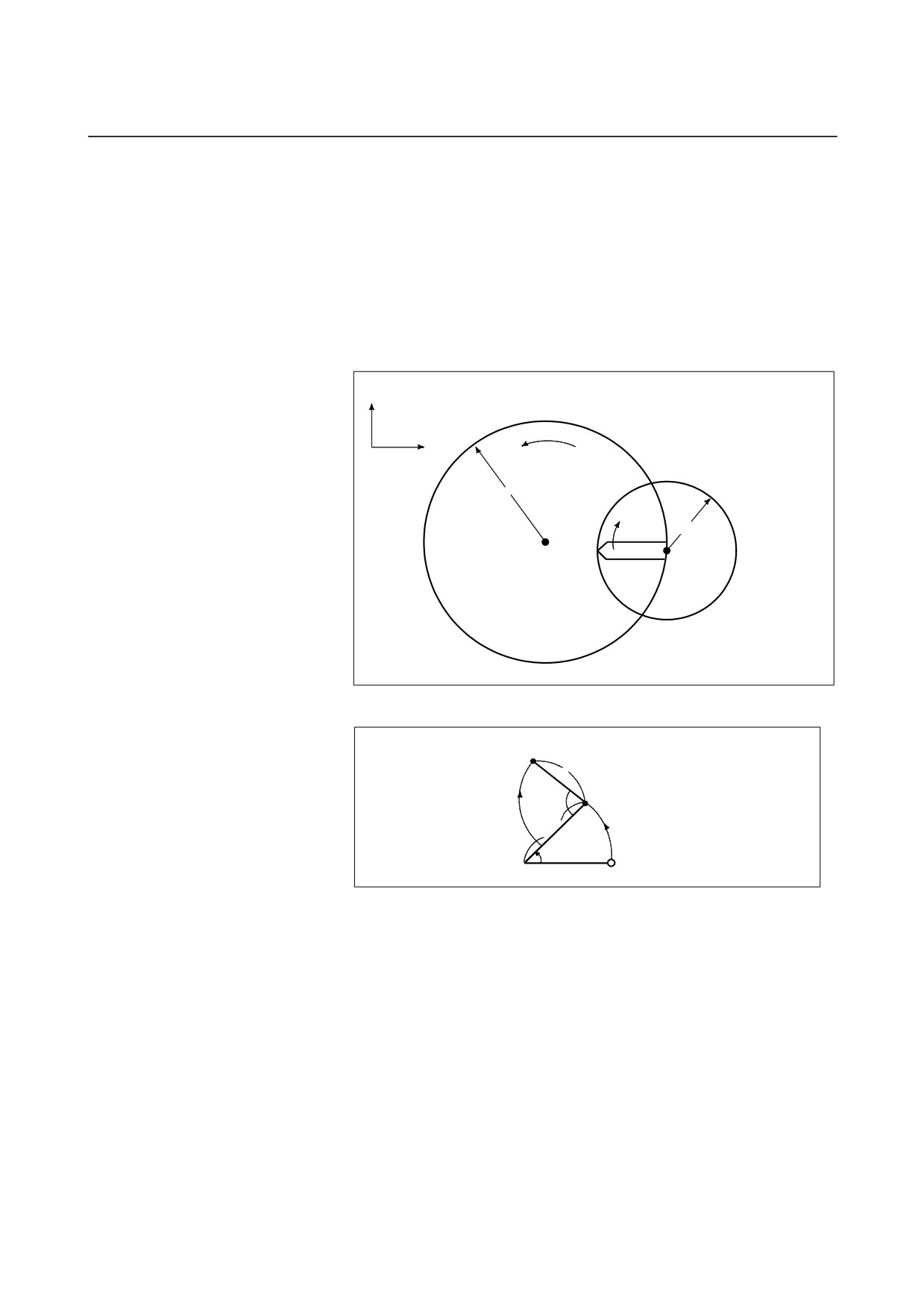
In the figure below the radius of tool and workpiece are A and B, and
the angular speeds of tool and workpiece are α and β. The origin of
XY Cartesian coordinates is assumed to be the center of the
workpiece.
Simplifying the explanation, consider that the tool center exists at the
position
Po (A, 0) on the workpiece periphery, and the tool nose starts from
position Pto (A-B, 0).
A : Workpiece radius
Y
B : Rool radius
α : Workpiece angular speed
β : Tool angular speed
X
Angular speed α
A
B
Pto
Tool
(0,0)
Po
Angular
Workpiece
speed β
Po
(A, 0)
Pto (A-B, 0)
Fig. 7.1 (b) Principle of polygon turning
Pt (Xt, Yt)
B
P
βt
A
αt
Start point
(0, 0)
Fig. 7.1 (c) Tool nose position
In this case, the tool nose position Pt (Xt, Yt) after time t is expressed
by equations 1 and 2:
Xt=Acosαt-Bcos(β-α)t
(Equation 1)
Yt=Asinαt+Bsin(β-α)t
(Equation 2)
Assuming that the rotation ration of workpiece to tool is 1:2, namely,
β=2α, equations 1 and 2 are modified as follows:
Xt=Acosαt-Bcosαt=(A-B)cosαt
(Equation 1)'
Xt=Asinαt+Bsinαt=(A+B)sinαt
(Equation 2)'
These equations indicate that the tool nose path draws an ellipse with
longer diameter A+B and shorter diameter A-B.
Then consider the case when one tool is set at 180° symmetrical
positions, for a total of two. A square can be machined with these
tools as shown below.
- 343 -