FANUC Series 0i-MODEL D, Series 0i Mate-MODEL D. For Lathe System USER’S MANUAL - page 9
5.COMPENSATION FUNCTION
PROGRAMMING
B-64304EN-1/01
5.3.5
Prevention of Overcutting Due to Tool Nose Radius
Compensation
Explanation
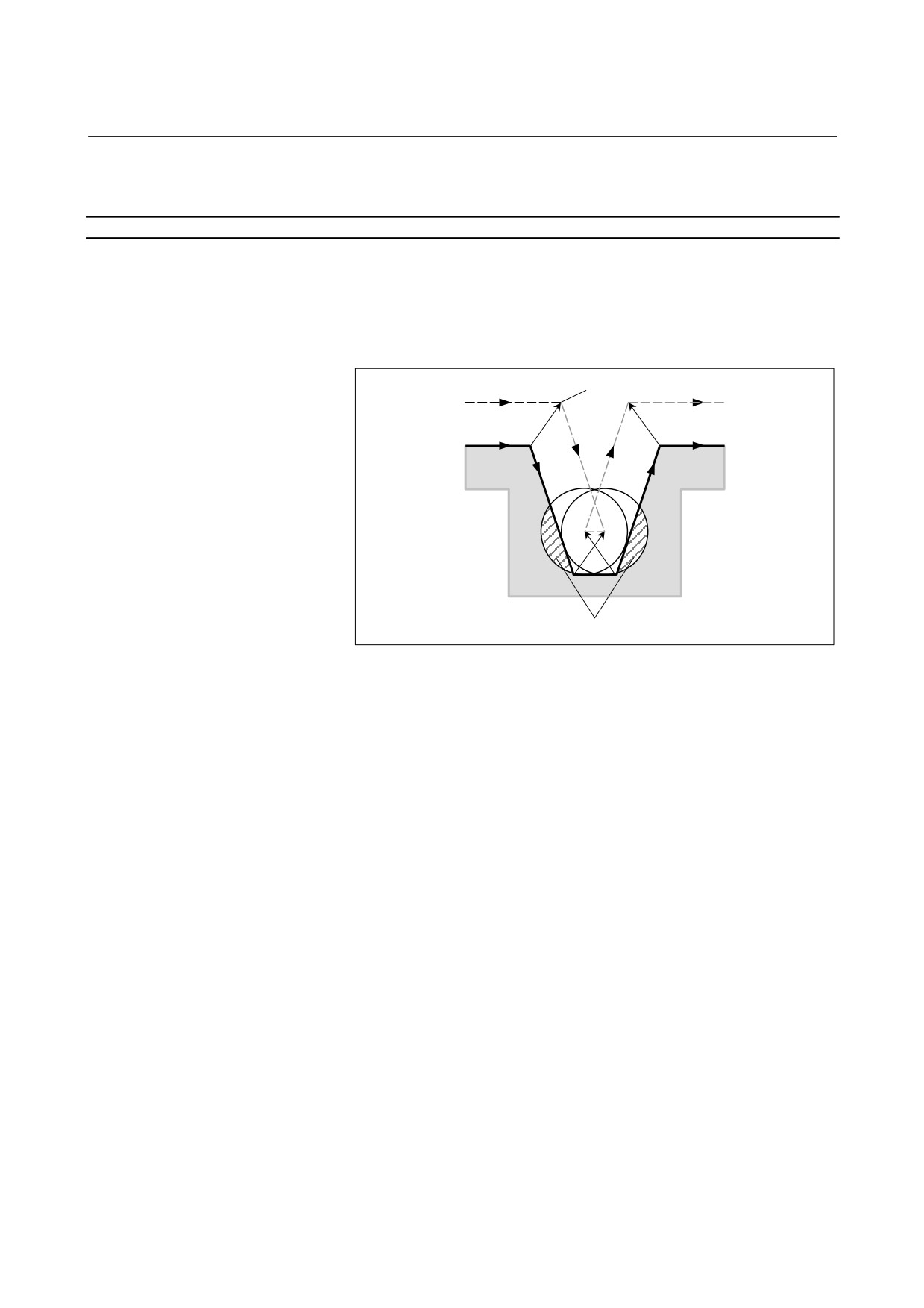
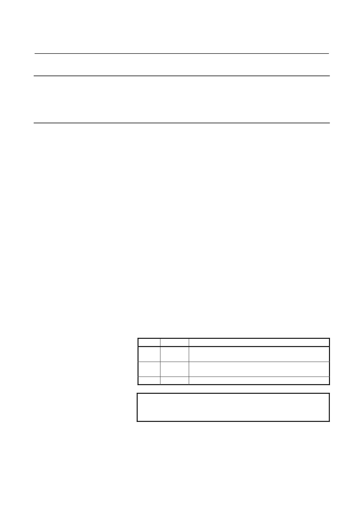
- Machining a groove smaller than the diameter of the tool nose
Since the tool nose radius compensation forces the path of the center
of the tool nose radius to move in the reverse of the programmed
direction, overcutting will result. In this case an alarm is displayed and
the CNC stops at the start of the block.
Tool nose radius
An alarm is displayed and
center path
the operation stops
Programmed path
Workpiece
Overcutting if the operation would not stop
Fig. 5.3.5 (a) Machining a groove smaller than the diameter of the tool
nose
- 224 -
B-64304EN-1/01
PROGRAMMING
5.COMPENSATION FUNCTION
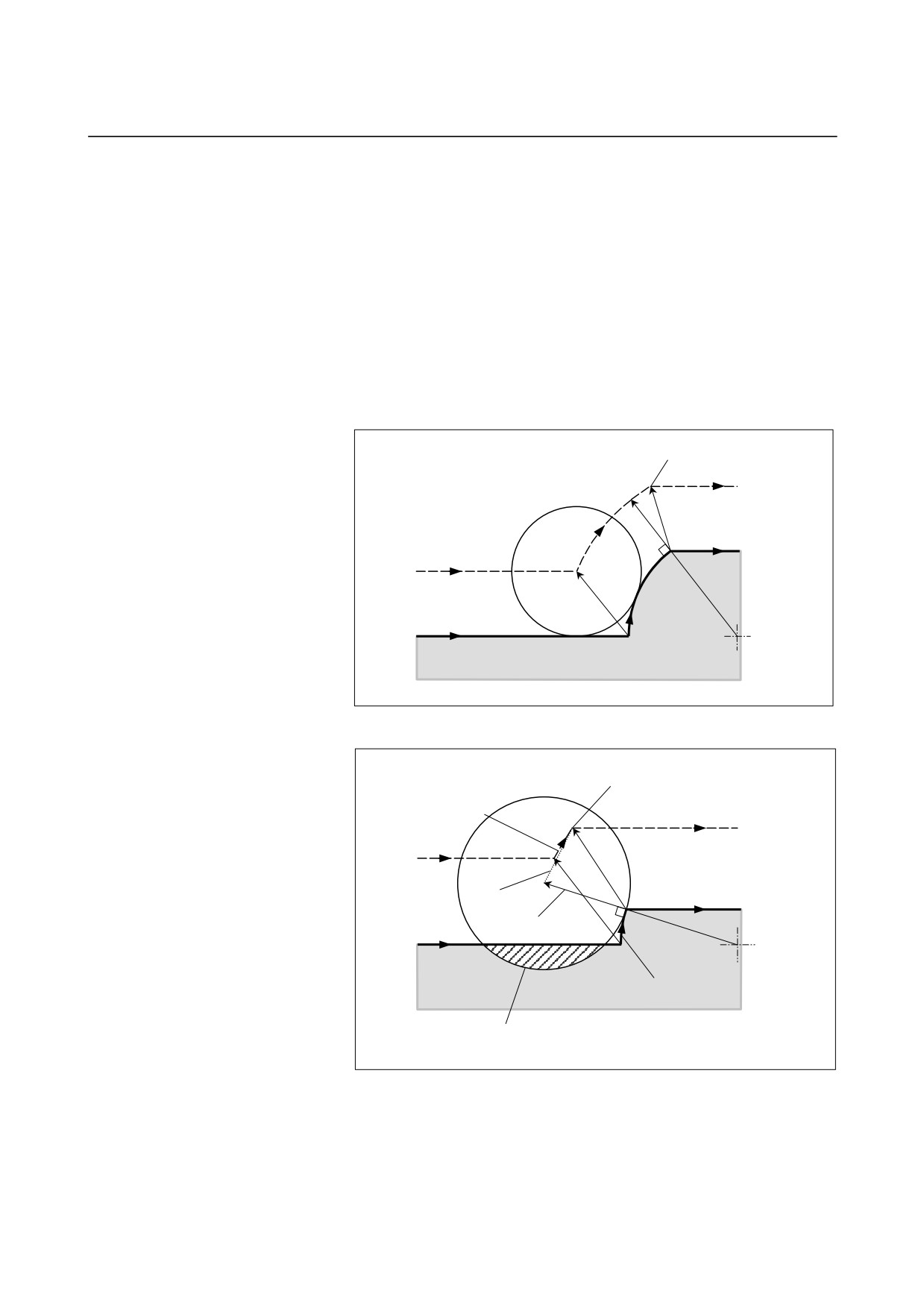
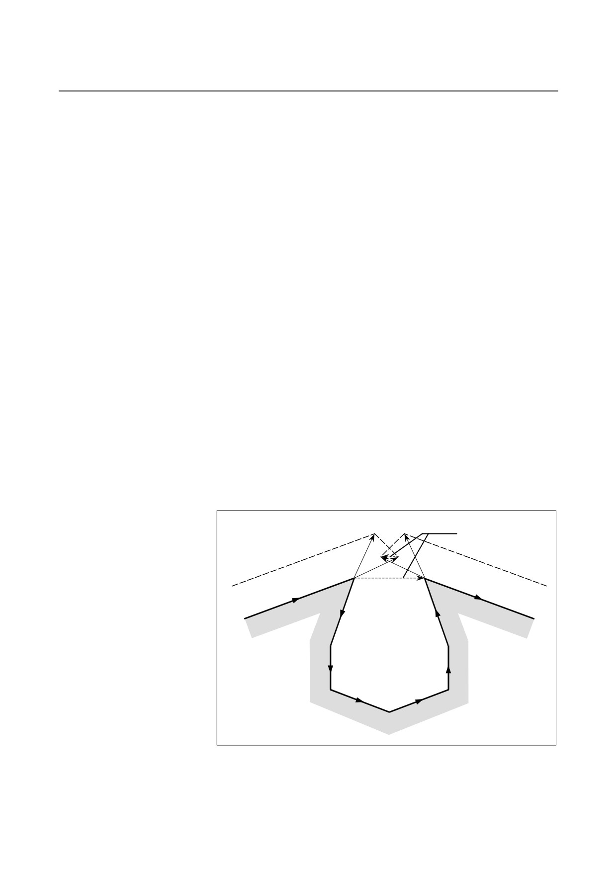
- Machining a step smaller than the tool nose radius
For a figure in which a workpiece step is specified with an arc, the
tool nose radius center path will be as shown in Fig. 5.3.5 (b). If the
step is smaller than the tool nose radius, the tool nose radius center
path usually compensated as shown in Fig. 5.3.5 (c) may be in the
direction opposite to the programmed path. In this case, the first
vector is ignored, and the tool moves linearly to the second vector
position. The single block operation is stopped at this point. If the
machining is not in the single block mode, the cycle operation is
continued.
If the step is of linear, no alarm will be generated and cut correctly.
However uncut part will remain.
Single block stop point
S
Tool nose radius
center path
Programmed path
S
Arc center
Workpiece
Fig. 5.3.5 (b) Machining a step larger than the tool nose radius
Single block stop point
Linear movement
S
Tool nose radius center path
Path to be taken if
the
Programmed path
vector is not ignored
The first vector is ignored
Arc center
Arc
Workpiece
An overcutting will result if the first vector is not ignored.
However, tool moves linearly.
Fig. 5.3.5 (c) Machining a step smaller than the tool nose radius
- 225 -
5.COMPENSATION FUNCTION
PROGRAMMING
B-64304EN-1/01
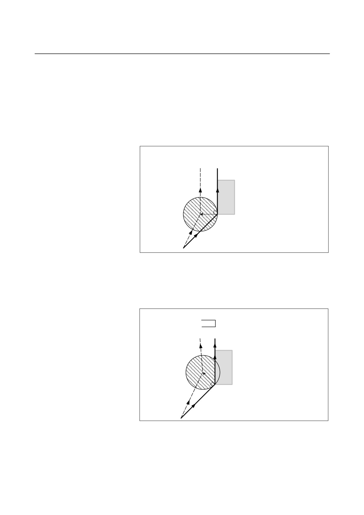
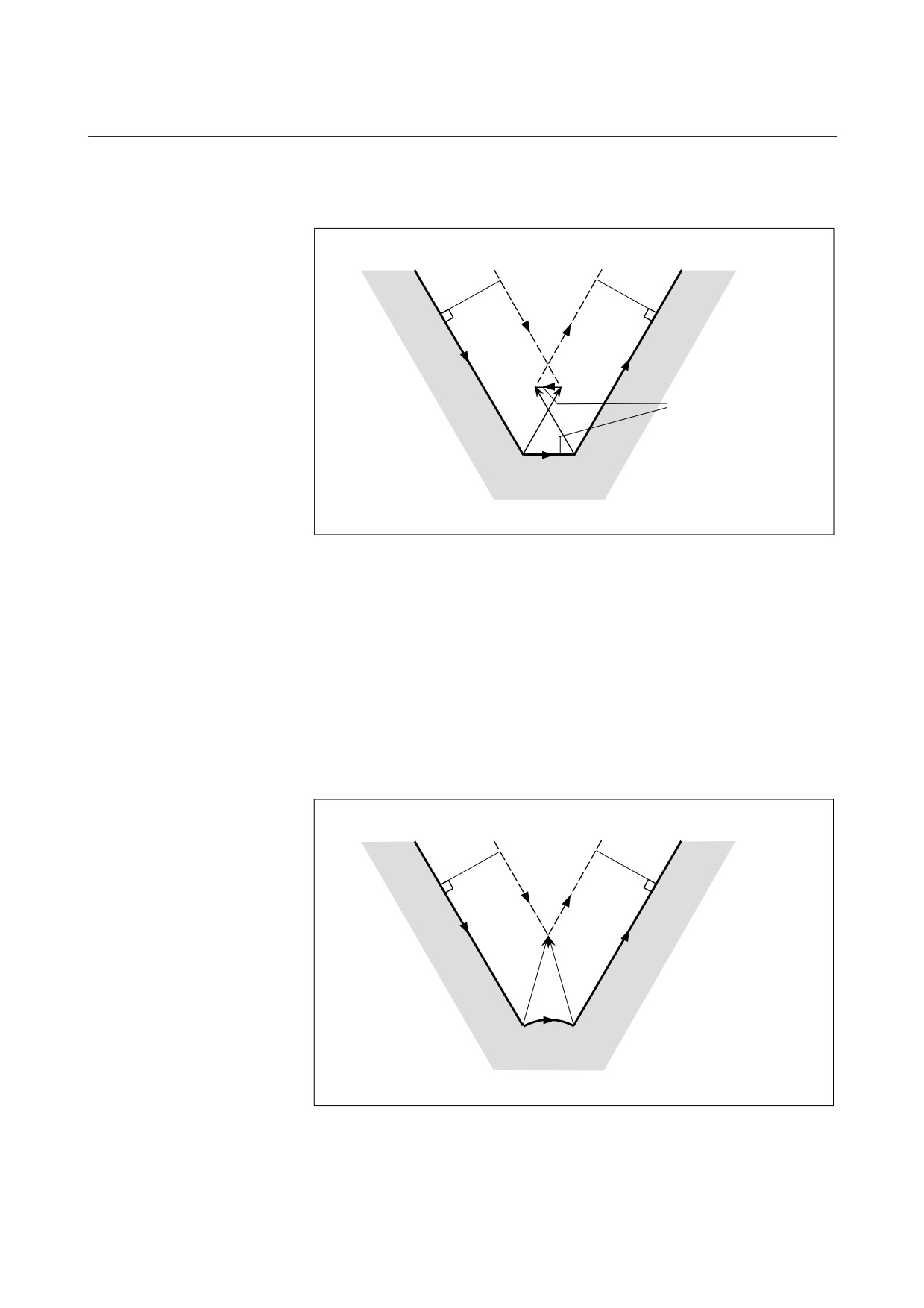
- Starting compensation and cutting along the Z-axis
It is usually used such a method that the tool is moved along the Z
axis after the tool nose radius compensation (normally XY plane) is
effected at some distance from the workpiece at the start of the
machining. In the case above, if it is desired to divide the motion
along the Z axis into rapid traverse and cutting feed, follow the
procedure below.
Let us consider the following program, assuming the number of blocks
to read in tool nose radius compensation mode
(parameter
(No.
19625)) to be 3.
N1 G00 G41 U500.0 V500.0 T0101 ;
N3 G01 W-300.0 F100 ;
N6 V1000.0 F200 ;
After compensation
N6
N3:Move command in Z axis (one block)
N1
In the program example above, when executing block N1, blocks N3
and N6 are also entered into the buffer storage, and by the relationship
among them the correct compensation is performed as in the figure
above.
Then, suppose that the block N3 (move command in Z axis) is divided
into N3 and N5.
N1 G00 G41 U500.0 V500.0 T0101 ;
N3 G01 W-250.0 ;
N5 G01 W-50.0 F100 ;
N6 V1000.0 F200 ;
After compensation
Workpiece
N6
N3, N5:Move command for the Z axis (two blocks)
N1
At this time, because the number of blocks to read is 3, blocks up to
N5 can be read at the start of N1 compensation, but block N6 cannot
be read. As a result, compensation is performed only on the basis of
the information in block N1, and a vertical vector is created at the end
of the compensation start block. Usually, therefore, overcutting will
result as shown in the figure above.
- 226 -
B-64304EN-1/01
PROGRAMMING
5.COMPENSATION FUNCTION
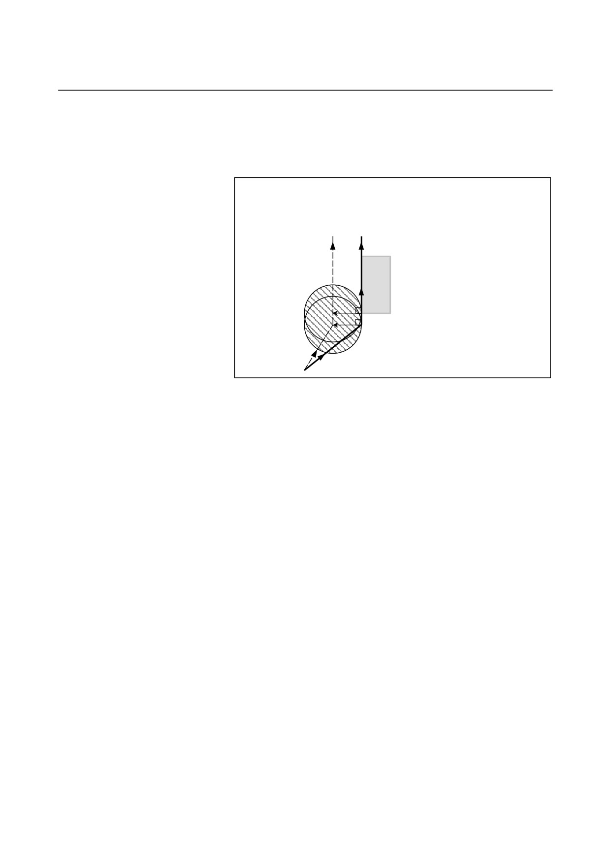
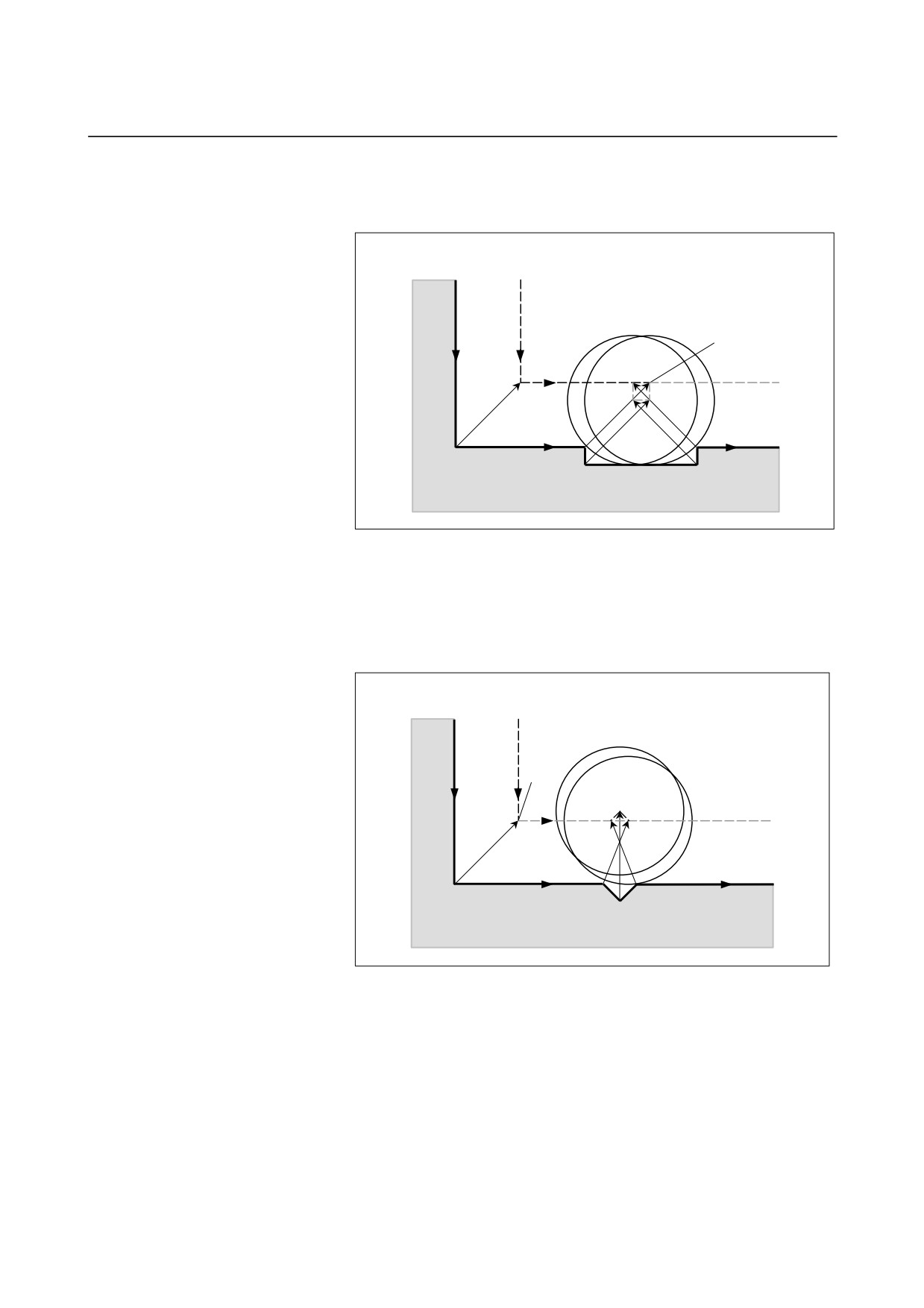
In such a case, it is possible to prevent overcutting by specifying a
command with the exactly the same direction as the advance direction
immediately before movement along the Z axis beforehand, after the
tool is moved along the Z axis using the above rule.
N1 G00 G41 U500.0 V400.0 T0101 ;
N2 V100.0 ;
N3 W-250.0 ;
N5 G01 W-50.0 F100 ;
N6 V1000.0 F200 ;
After compensation
N6
Workpiece
N3, N5 : Move command for the Z axis (2 blocks)
N2
N1
As the block N2 has the move command in the same direction as that
of the block N6, the correct compensation is performed.
Alternatively, it is possible to prevent overcutting in the same way by
specifying an IJ type vector with the same direction as the advance
direction in the start-up block, as in N1 G00 G41 U500.0 V500.0 I0 J1
T0101;, after the tool has moved along the Z axis.
- 227 -
5.COMPENSATION FUNCTION
PROGRAMMING
B-64304EN-1/01
5.3.6
Interference Check
Tool overcutting is called interference. The interference check
function checks for tool overcutting in advance. However, all
interference cannot be checked by this function. The interference
check is performed even if overcutting does not occur.
Explanation
- Condition under which an interference check is possible
To perform an interference check, it is necessary to read at least three
blocks with tool movement. If, therefore, three or more blocks with
tool movement cannot be read in offset mode because blocks without
tool movement, such as independent auxiliary function and dwell, are
specified in succession, excessive or insufficient cutting may occur
because an interference check fails. Assuming the number of blocks
to read in offset mode, which is determined by parameter (No. 19625),
to be N and the number of commands in those N blocks without tool
movement that have been read to be M, the condition under which an
interference check is possible is
(N - 3) ≥ M.
For example, if the maximum number of blocks to read in offset mode
is 8, an interference check is possible even if up to five blocks without
tool movement are specified. In this case, three adjacent blocks can
be checked for interference, but any subsequent interference that may
occur cannot be detected.
- Interference check method
Two interference check methods are available, direction check and
circular angle check. Parameter CNC (No. 5008#1) and parameter
CNV (No. 5008#3) are used to specify whether to enable these
methods.
CNV
CNC
Operation
0
0
An interference check is enabled, and a direction check
and a circular angle check can be performed.
0
1
An interference check is enabled, and only a circular
angle check is performed.
1
-
An interference check is disabled.
NOTE
There are no settings for performing a direction
check only.
- 228 -
B-64304EN-1/01
PROGRAMMING
5.COMPENSATION FUNCTION
- Interference reference <1> (direction check)
Assuming the number of blocks to read during tool nose radius
compensation to be N, a check is first performed on the compensation
vector group calculated in (block 1 - block 2) to be output this time
and the compensation vector group calculated in (block N-1 - block
N); if they intersect, they are judged to interfere. If no interference is
found, a check is performed sequentially in the direction toward the
compensation vector group to be output this time, as follows:
(Block 1 - block 2) and (block N-2 - block N-1)
(Block 1 - block 2) and (block N-3 - block N-2)
:
:
(Block 1 - block 2) and (block 2 - block 3)
Even if multiple number of compensation vector groups are generated,
a check is performed on all pairs.
The judgment method is as follows:
For a check on the
compensation vector group in (block 1 - block 2) and those in (block
N-1 - block N), the direction vector from the specified (end point of
block 1) to the (end point of block N-1) is compared with the direction
vector from the (point resulting from adding the compensation vector
to be checked to the end of block 1) to the (point resulting from
adding the compensation vector to be checked to the end of block
N-1), and if the direction is 90o or greater or 270o or less, they are
judged to intersect and interfere. This is called a direction check.
Example of interference standard <1>
(If the block 1 end-point vector intersects with the block 7 end-point
vector)
The direction differs by
180°.
Tool center path
Programmed path
Block 2
Block 7
Block 1
Block 8
Block 3
Block 6
Block 4
Block 5
- 229 -
5.COMPENSATION FUNCTION
PROGRAMMING
B-64304EN-1/01
Example of interference standard <1>
(If the block 1 end-point vector intersects with the block 2 end-point
vector)
Tool nose radius
Programmed path
center path
Block 1
The directions of
these two paths are
different (180°).
Block 2
- Interference reference <2> (circular angle check)
In a check on three adjacent blocks, that is, a check on the
compensation vector group calculated on (block 1 - block 2) and the
compensation vector group calculated on (block 2 - block 3), if block
2 is circular, a check is performed on the circular angle between the
start and end points of the programmed path and the circular angle of
the start and end point of the post-compensation path, in addition to
direction check <1>. If the difference is 180o or greater, the blocks
are judged to interfere. This is called a circular angle check.
Example of <2> (if block 2 is circular and the start point of the
post-compensation arc coincide with the end point)
Tool nose radius
Programmed path
center path
Block 3
Block 1
Programmed path
Block 2
- 230 -
B-64304EN-1/01
PROGRAMMING
5.COMPENSATION FUNCTION
- When interference is assumed although actual interference does not occur
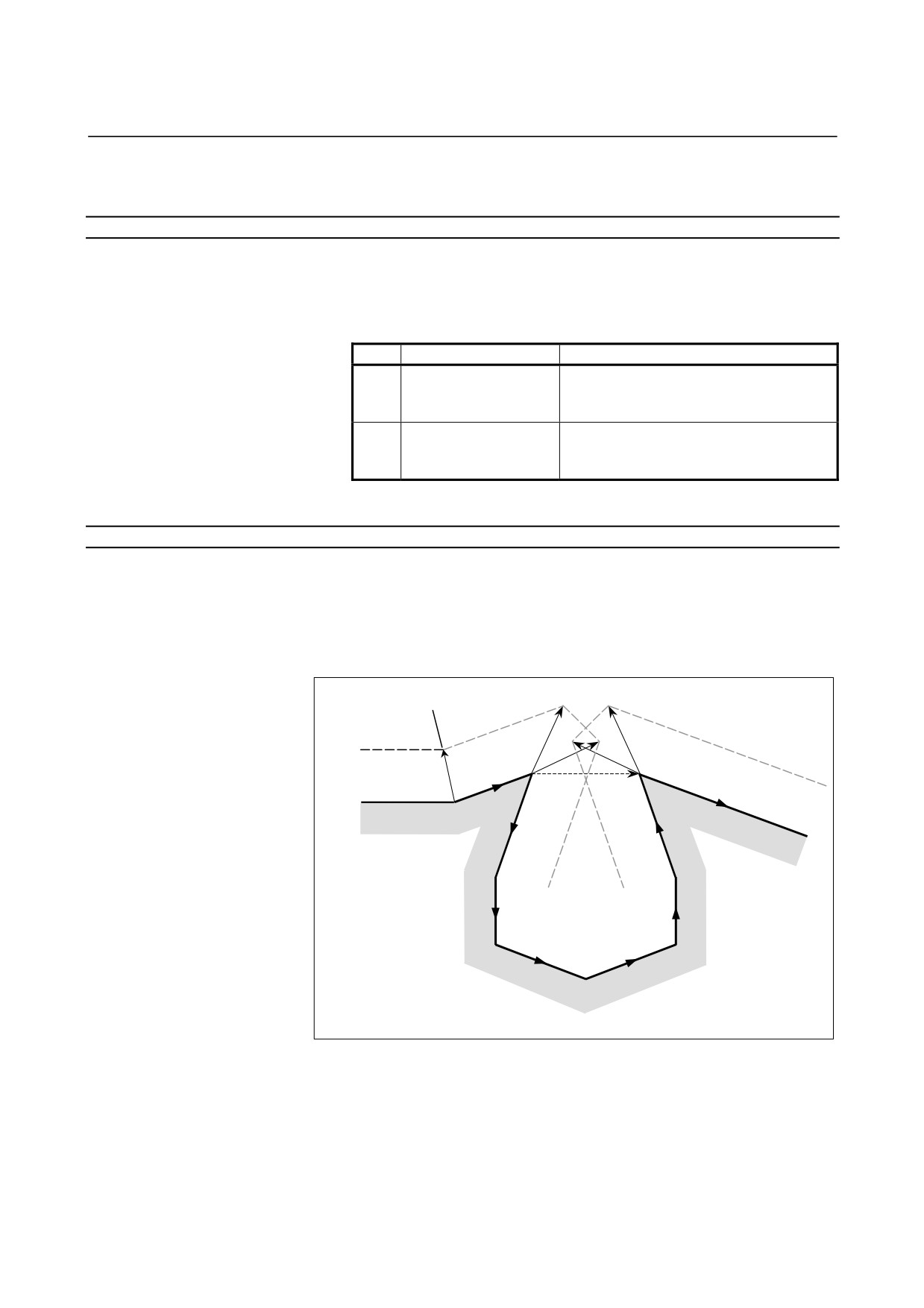
<1> Depression which is smaller than the tool nose radius
compensation value
Programmed
path
Tool nose radius center path
Stopped
A
C
B
There is no actual interference, but since the direction
programmed in block B is opposite to that of the path after the
tool nose radius compensation, the tool stops and an alarm is
displayed.
<2> Groove which is smaller than the tool nose radius compensation
value
Programmed
path
Tool nose radius center path
Stopped
A
B
C
Like <1>, an alarm is displayed because of the interference as the
direction is reverse in block B.
- 231 -
5.COMPENSATION FUNCTION
PROGRAMMING
B-64304EN-1/01
5.3.6.1 Operation to be performed if an interference is judged to
occur
Explanation
The operation to be performed if an interference check judges that an
interference (due to overcutting) occurs can be either of the following
two, depending on the setting of parameter CAV (No. 19607#5).
CAV
Function
Operation
An alarm stop occurs before the execution
Interference check
0
of the block in which overcutting
alarm function
(interference) occurs.
The tool path is changed so that
Interference check
1
overcutting (interference) does not occur,
avoidance function
and processing continues.
5.3.6.2 Interference check alarm function
Explanation
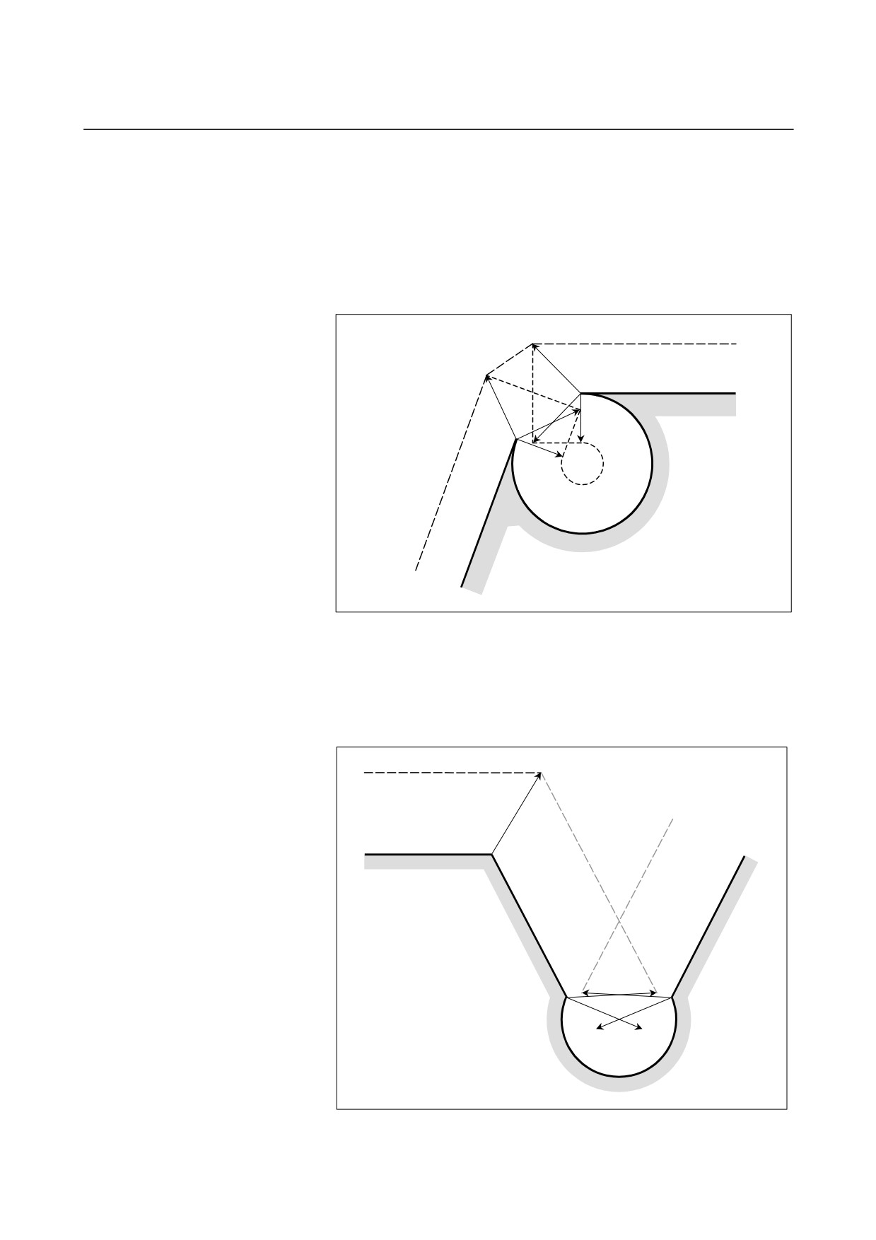
- Interference other than those between adjacent three blocks
If the end-point vector of block 1 and the end-point vector of block 7
are judged to interfere as shown in the figure, an alarm will occur
before the execution of block 1 so that the tool stops. In this case,
the vectors will not be erased.
Stopped
Tool nose radius
center path
Block 1
Block 8
Programmed path
Block 2
Block 7
Block 3
Block 6
Block 4
Block 5
- 232 -
B-64304EN-1/01
PROGRAMMING
5.COMPENSATION FUNCTION
- Interference between adjacent three blocks
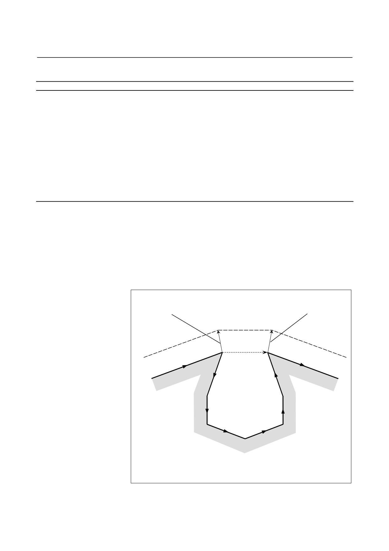
If an interference is judged to occur between adjacent three blocks, the
interfering vector, as well as any vectors existing inside of it, is erased,
and a path is created to connect the remaining vectors. In the
example shown in the figure below, V2 and V5 interfere, so that V2
and V5 are erased, so are V3 and V4, which are inside of them, and V1
is connected to V6. The operation during this time is linear
interpolation.
V6
V1
V2
V5
V4
V3
Tool center path
Programmed path
If, after vector erasure, the last single vector still interferes, or if there
is only one vector at the beginning and it interferes, an alarm will
occur immediately after the start of the previous block (end point for a
single block) and the tool stops. In the example shown in the figure
below, V2 and V3 interfere, but, even after erasure, an alarm will occur
because the final vectors V1 and V4 interfere.
Stopped
Tool center path
Programmed path
V4
V1
V3
V2
- 233 -
5.COMPENSATION FUNCTION
PROGRAMMING
B-64304EN-1/01
5.3.6.3 Interference check avoidance function
Overview
If a command is specified which satisfies the condition under which
the interference check alarm function generates an interference alarm,
this function suppresses the generation of the interference alarm, but
causes a new compensation vector to be calculated as a path for
avoiding interference, thereby continuing machining. For the path
for avoiding interference, insufficient cutting occurs in comparison
with the programmed path. In addition, depending on the specified
figure, no path for avoiding interference can be determined or the path
for avoiding interference may be judged dangerous. In such a case,
an alarm stop will occur. For this reason, it is not always possible to
avoid interference for all commands.
Explanation
- Interference avoidance method
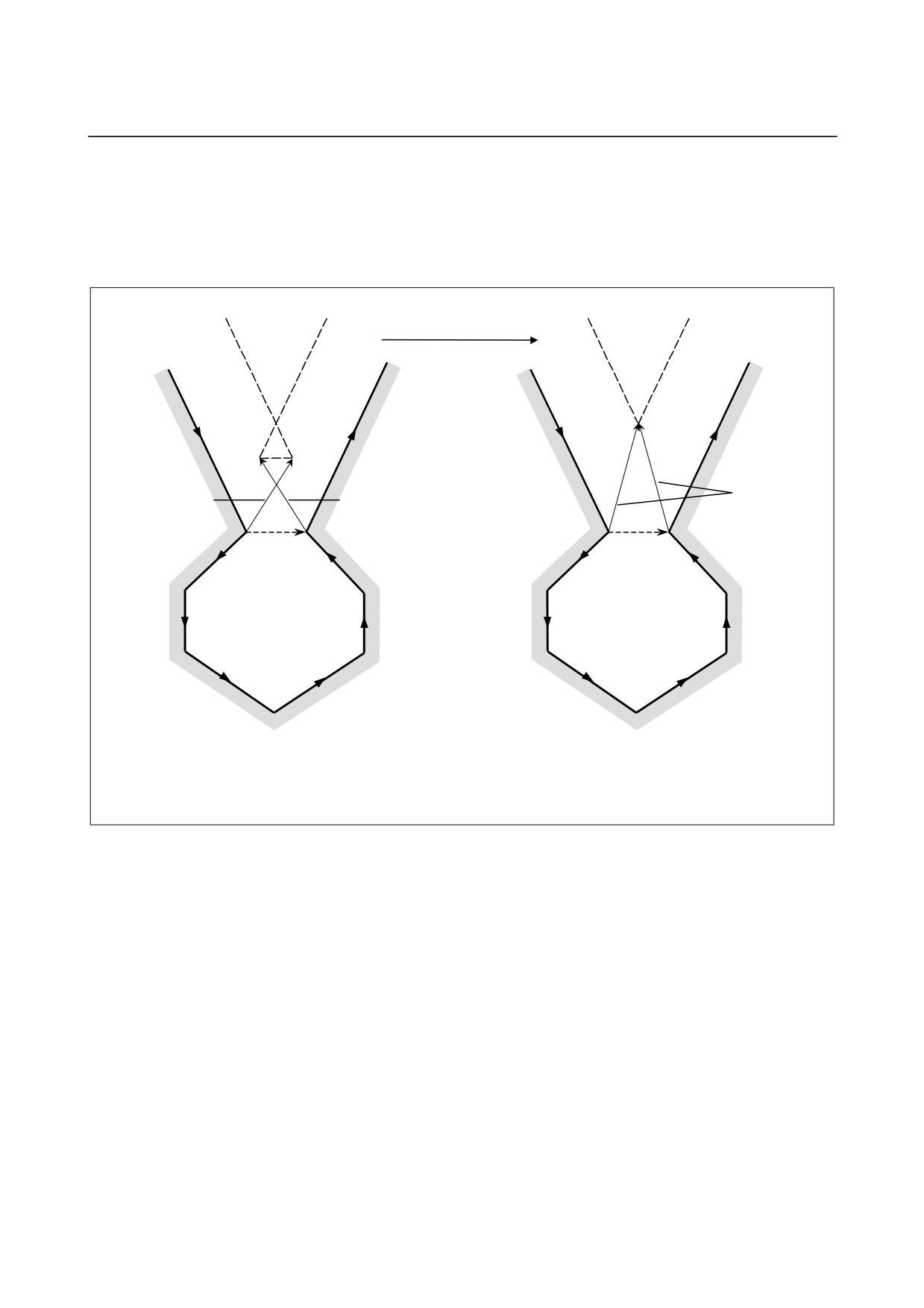
Let us consider a case in which an interference occurs between the
compensation vector between
(block
1
- block
2) and the
compensation vector between (block N-1 - block N). The direction
vector from the end point of block 1 to the end point of block N-1 is
called a gap vector. At this time, a post-compensation intersection
vector between
(block
1 - gap vector) and a post-compensation
intersection vector between (gap vector - block N) is determined, and
a path connecting them is created.
Post-compensation intersection vector
Post-compensation intersection vector
between gap vector and block 8
between block 1 and gap vector
Movement o f block 7
Post-compensation
path
Gap vector
Block 1
Block 8
Block 2
Block 7
Programmed path
Block 3
Block 6
Block 4
Block 5
In this case, the post-compensation end points of blocks 2 to 6 coincide with the end
point of block 1. Thus, after compensation, blocks 2 to 6 will be blocks without tool
movement.
- 234 -
B-64304EN-1/01
PROGRAMMING
5.COMPENSATION FUNCTION
If the post-compensation intersection vector of (block 1 - gap vector)
and the post-compensation intersection vector of (gap vector - block
N) further intersect, vector erasure is first performed in the same way
as in "Interference between adjacent three blocks". If the last vectors
that remains still intersects, the post-compensation intersection vector
of (block 1 - block N) is re-calculated.
Post-compensation path
Re-calculation
Programmed path
Block 1
Block 8
Block 1
Block 8
Post-
Post-compensation
compensation
Post-compensation
intersection vector
intersection
intersection between
vector between
between block 1
gap vector and block 8
and gap vector
block 1 and
block 8
Block 2
Gap vector
Block 7
Block 2
Block 7
Block 3
Block 3
Block 6
Block 6
Block 4
Block 4
Block 5
Block 5
In this case, the post-compensation end points of blocks 2 to 7
coincide with the end point of block 1. Thus, after compensation,
blocks 2 to 7 will be blocks without tool movement.
- 235 -
5.COMPENSATION FUNCTION
PROGRAMMING
B-64304EN-1/01
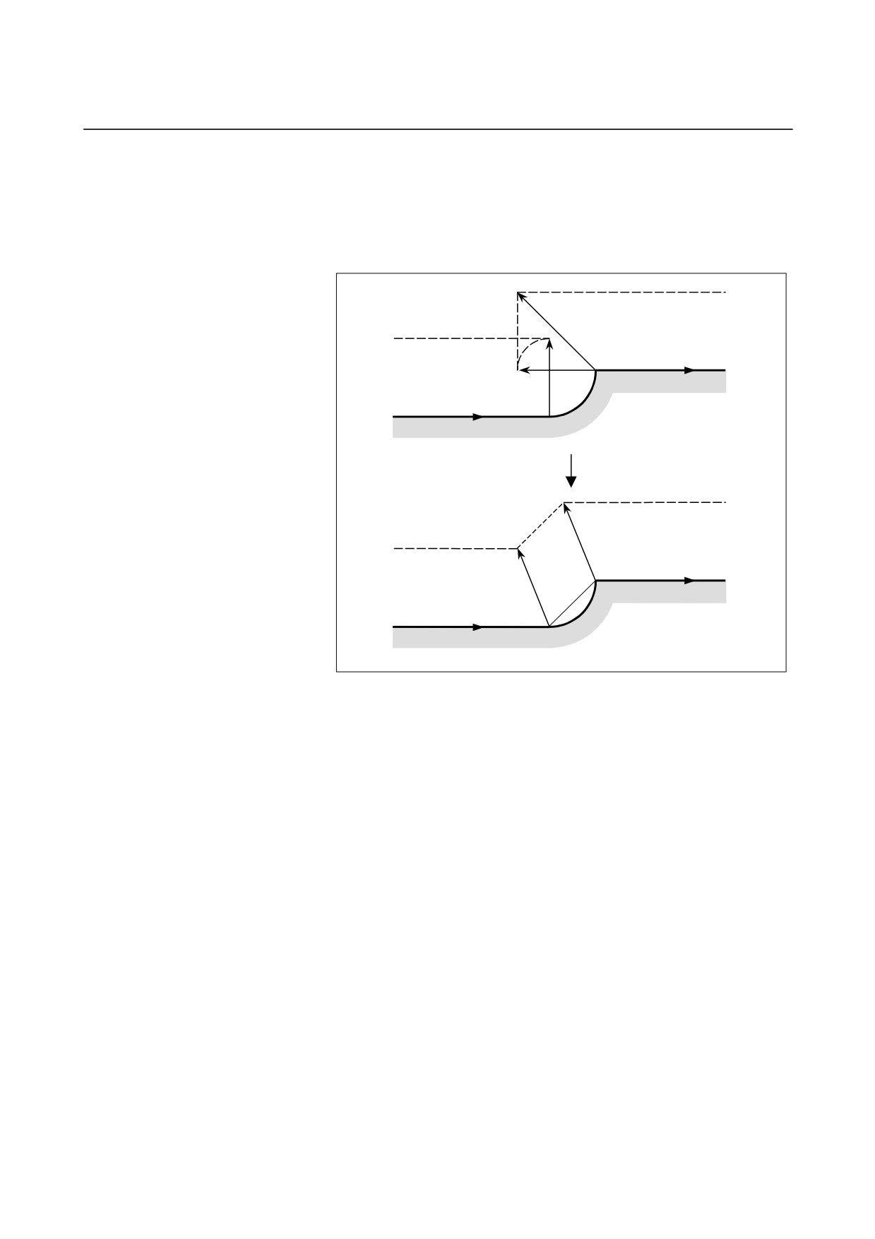
If the tool nose radius compensation value is greater than the radius of
the specified arc as shown in the figure below, and a command is
specified which results in compensation with respect to the inside of
the arc, interference is avoided by performing intersection calculation
with an arc command being assumed a linear one. In this case,
avoided vectors are connected with linear interpolation.
Post-compensation path
Programmed path
- 236 -
B-64304EN-1/01
PROGRAMMING
5.COMPENSATION FUNCTION
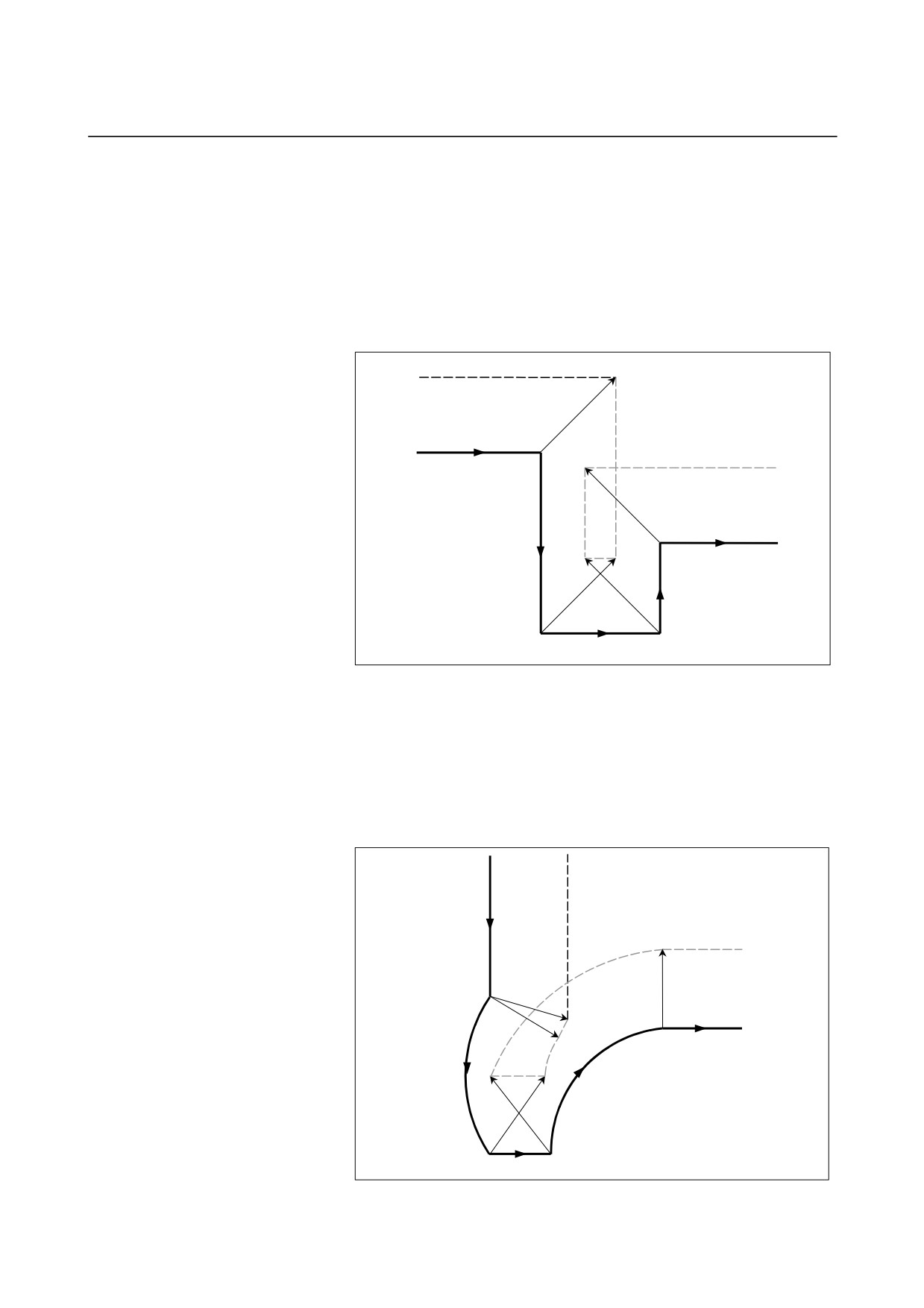
- If no interference avoidance vector exists
If the parallel pocket shown in the figure is to be machined, the
end-point vector of block 1 and the end-point vector of block 2 are
judged to interfere, and an attempt is made to calculate, as an
interference avoidance vector, the intersection vector of the
post-compensation path of block 1 and the post-compensation path of
block 3. In this case, because blocks 1 and 3 are parallel to each
other, no intersection exists. In this case, an alarm will occur
immediately before block 1 and the tool will stop.
Stopped
Tool center path
Programmed path
Block 1
Block 3
Block 2
If the circular pocket shown in the figure is to be machined, the
end-point vector of block 1 and the end-point vector of block 2 are
judged to interfere, and an attempt is made to calculate, as an
interference avoidance vector, the intersection vector of the
post-compensation path of block 1 and the post-compensation path of
block
3.
In this case, because blocks
1 and 3 are circular, no
post-compensation intersection exists. In this case, an alarm will
occur immediately before block 1 and the tool will stop, as in the
previous example.
Programmed path
Tool center path
Stopped
Block 1
Block 3
Block 2
- 237 -
5.COMPENSATION FUNCTION
PROGRAMMING
B-64304EN-1/01
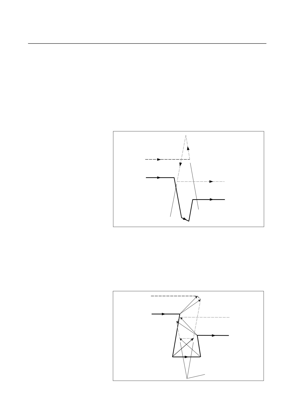
- If it is judged dangerous to avoid interference
If the acute-angle pocket shown in the figure is to be machined, the
end-point vector of block 1 and the end-point vector of block 2 are
judged to interfere, and an attempt is made to calculate, as an
interference avoidance vector, the intersection vector of the
post-compensation path of block 1 and the post-compensation path of
block 3. In this case, the movement direction of the post-avoidance
path extremely differs from the previously specified direction. If the
post-avoidance path extremely differs from that of the original
command (90° or greater or 270° or less), interference avoidance
operation is judged dangerous; an alarm will occur immediately before
block 1 and the tool will stop.
Post-compensation intersection of
blocks 1 and 3
Tool center path
Stopped
Programmed path
Block 1
Block 3
Block 2
If a pocket in which the bottom is wider than the top, such as that
shown in the figure, is to be machined, the end-point vector of block 1
and the end-point vector of block 2 are judged to interfere, and an
attempt is made to calculate, as an interference avoidance vector, the
intersection vector of the post-compensation path of block 1 and the
post-compensation path of block 3. In this case, the relation between
blocks 1 and 3 is judged an outer one, the post-avoidance path results
in overcutting as compared with the original command. In such a
case, interference avoidance operation is judge dangerous; an alarm
will occur immediately before block 1 and the tool will stop.
Stopped
Tool center path
Programmed path
Block 1
Block 3
Block 2
Post-compensation intersection
of blocks 1 and 3
- 238 -
B-64304EN-1/01
PROGRAMMING
5.COMPENSATION FUNCTION
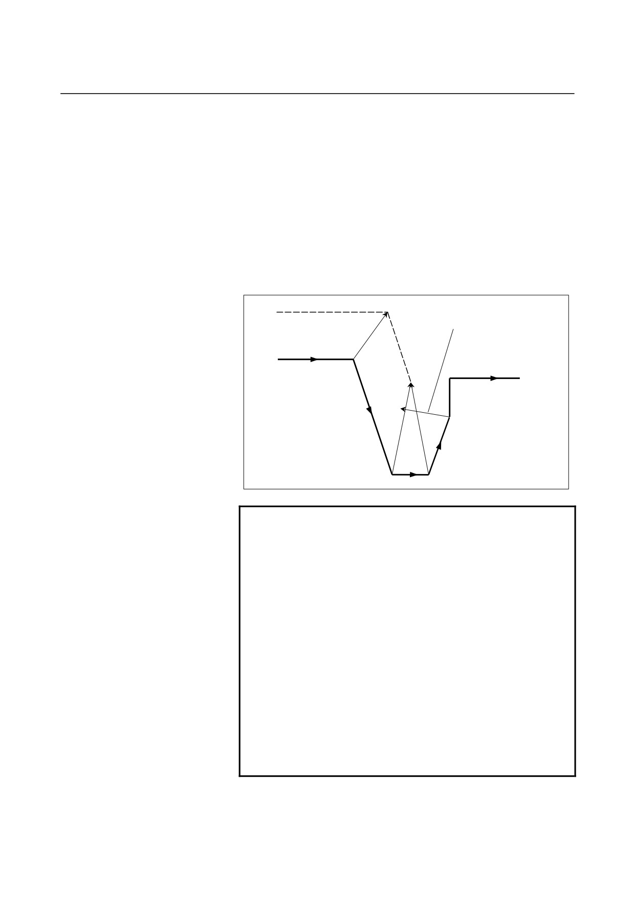
- If further interference with an interference avoidance vector occurs
If the pocket shown in the figure is to be machined, if the number of
blocks to read is 3, the end-point vector of block 1 and the end-point
vector of block 2 are judged to interfere, and an attempt is made to
calculate, as an interference avoidance vector, the intersection vector
of the post-compensation path of block 1 and the post-compensation
path of block 3. In this case, however, the end-point vector of block
3 that is to be calculated next further interferes with the previous
interference avoidance vector. If a further interference occurs to the
interference avoidance vector once created and output, the movement
in the block will not be performed; an alarm will occur immediately
before the block and the tool will stop.
The intersection vectors of
blocks 3 and 4 further
Tool center path
interfere.
Programmed path
Sropped
Block 5
Block 4
Block 1
Block 3
Block 2
NOTE
1 For "If it is judged dangerous to avoid interference"
and "If further interference with an interference
avoidance vector occurs", by setting parameter
NAA (No. 19607#6) appropriately, it is possible to
suppress an alarm to continue machining. For "If
no interference avoidance vector exists", however,
it is not possible to avoid an alarm regardless of the
setting of this parameter.
2 If a single block stop occurs during interference
avoidance operation, and an operation is performed
which differs from the original movement, such as
manual intervention, MDI intervention, tool nose
radius compensation value change, intersection
calculation is performed with a new path. If such
an operation is performed, therefore, an
interference may occur again although interference
avoidance has been performed once.
- 239 -
5.COMPENSATION FUNCTION
PROGRAMMING
B-64304EN-1/01
5.3.7
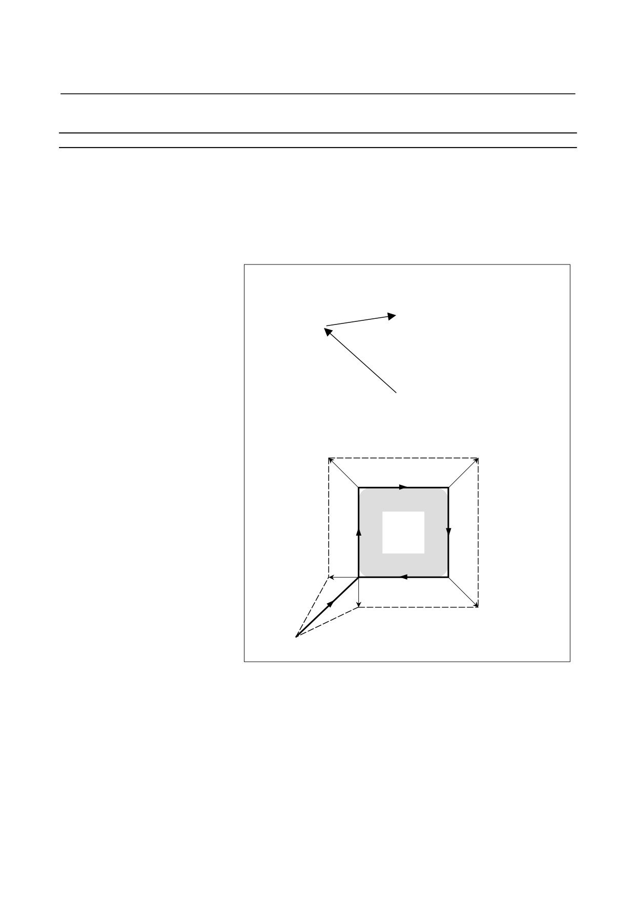
Tool Nose Radius Compensation for Input from MDI
Explanation
- MDI operation
During MDI operation, that is, if a program command is specified in
MDI mode in the reset state to make a cycle start, intersection
calculation is performed for compensation in the same way as in
memory operation/DNC operation. Compensation is performed in
the same way if a subprogram is called from program memory due to
MDI operation.
MDI command
Subprogram in program memory
G00 X0 Y0 ;
O9000 ;
M98 P9000 ;
N1 G41 G17 G01 U10.0 V10.0
M02 ;
T0101 ;
N2 V15.0 ;
N3 U15.0 ;
N4 V-15.0 ;
N5 U-15.0 ;
N6 G40 U-10.0 V-10.0 ;
M99 ;
N3
N2
N4
N1
N5
N6
- 240 -
B-64304EN-1/01
PROGRAMMING
5.COMPENSATION FUNCTION
- MDI intervention
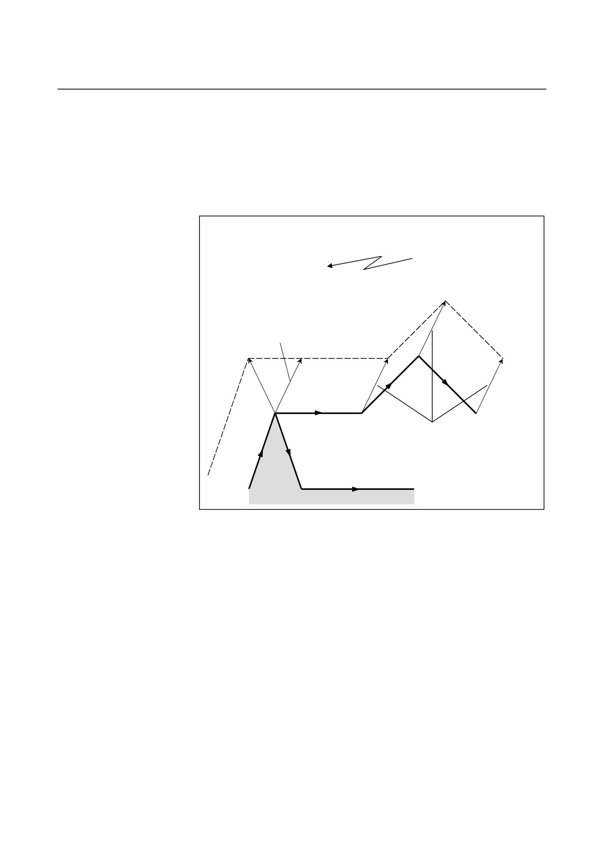
If MDI intervention is performed, that is, if a single block stop is
performed to enter the automatic operation stop state in the middle of
memory operation, DNC operation, and the like, and a program
command is specified in MDI mode to make a cycle start, tool nose
radius compensation does not perform intersection calculation,
retaining the last compensation vector before the intervention.
MEM mode
MDI intervention
(G41)
W30.0 ;
N2 U30.0 W10.0 ;
U20.0 W20.0 ;
N3 U-30.0 W10.0 ;
U-20.0 W20.0 ;
N4 W40.0 ;
Last compensation vector
MDI intervention
Retained compensation vector
N2 N3
N4
Program command
- 241 -
5.COMPENSATION FUNCTION
PROGRAMMING
B-64304EN-1/01
5.4
CORNER CIRCULAR INTERPOLATION (G39)
By specifying G39 in offset mode during tool nose radius
compensation, corner circular interpolation can be performed. The
radius of the corner circular interpolation equals the compensation
value.
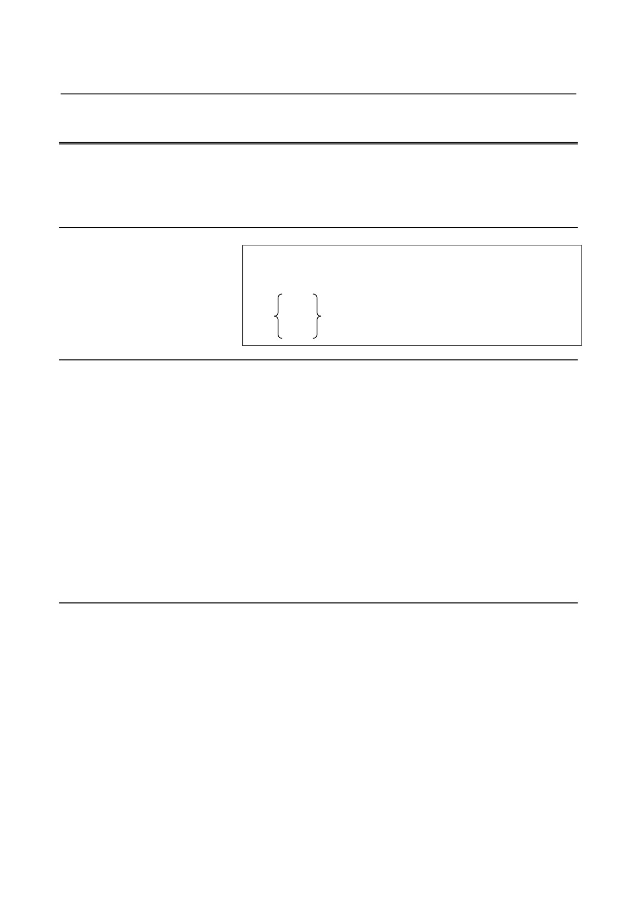
Format
In offset mode
G39 ;
or
I_J_
G39
I_K_
;
J_K_
Explanation
- Corner circular interpolation
When the command indicated above is specified, corner circular
interpolation in which the radius equals compensation value can be
performed. G41 or G42 preceding the command determines whether
the arc is clockwise or counterclockwise. G39 is a one-shot G code.
- G39 without I, J, or K
When G39; is programmed, the arc at the corner is formed so that the
vector at the end point of the arc is perpendicular to the start point of
the next block.
- G39 with I, J, and K
When G39 is specified with I, J, and K, the arc at the corner is formed
so that the vector at the end point of the arc is perpendicular to the
vector defined by the I, J, and K values.
Limitation
- Move command
In a block containing G39, no move command can be specified.
Otherwise, an alarm will occur.
- Inner corner
In an inner corner block, G39 cannot be specified. Otherwise,
overcutting will occur.
- Corner arc velocity
If a corner arc is specified with G39 in G00 mode, the corner arc block
velocity will be that of the F command previously specified.
- 242 -
B-64304EN-1/01
PROGRAMMING
5.COMPENSATION FUNCTION
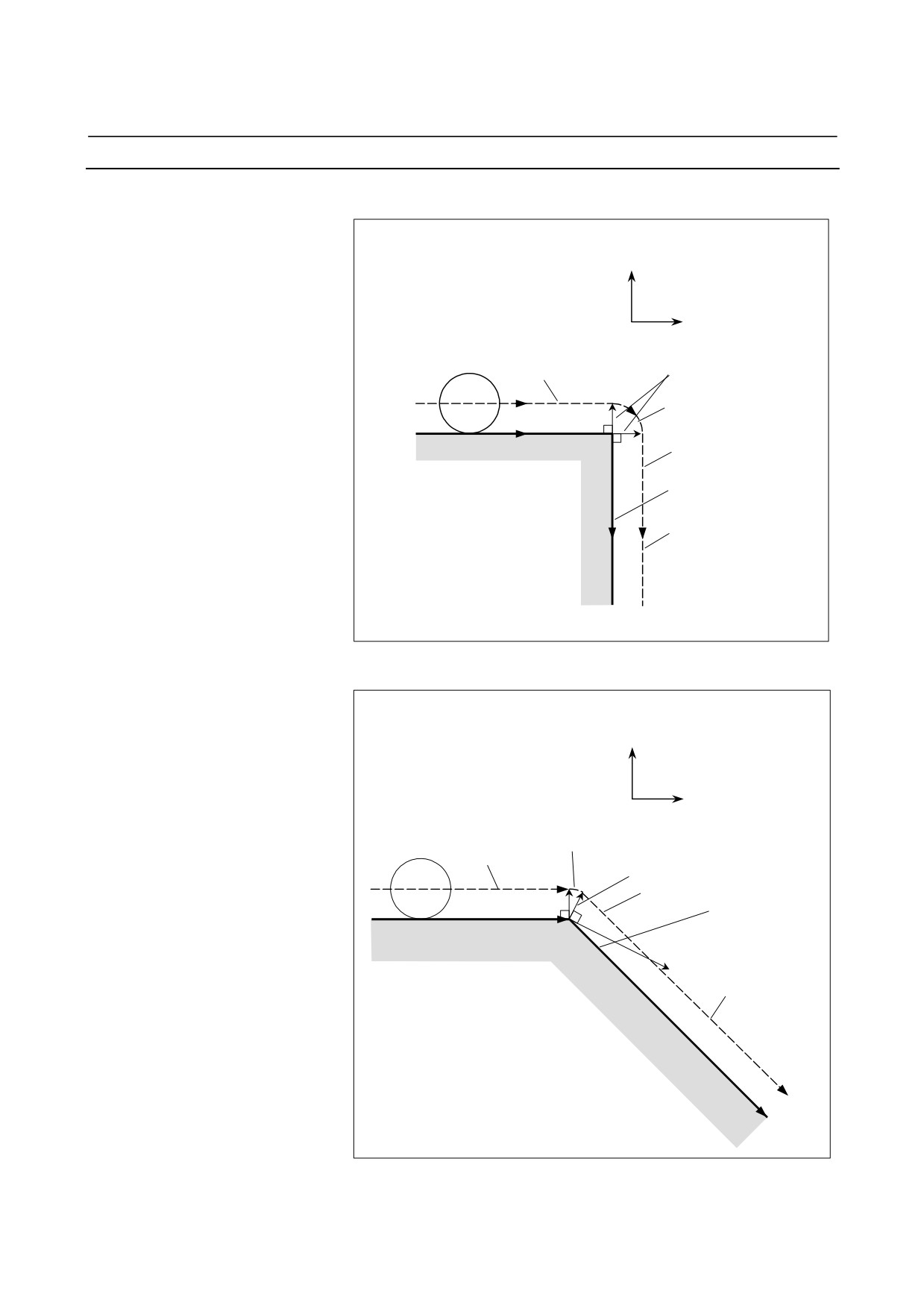
Example
- G39 without I, J, or K
:
:
(In offset mode)
N1 Z10.0
;
X axis
N2 G39 ;
N3 X-10.0 ;
:
:
Z axis
Block N1
Offset vector
Block N2 (Corner arc)
(10.0, 0.0)
Block N3
Programmed path
Tool nose radius
center path
(10.0, -10.0)
- G39 with I, J, and K
:
:
(In offset mode)
N1 Z10.0
;
X axis
N2 G39 I-1.0 K2.0 ;
N3 X-10.0 Z20.0 ;
:
:
Z axis
Block N2 (Corner arc)
Block N1
Offset vector
Block N3
Programmed
path
(10.0, 0.0)
(I=-1.0, K=2.0)
Tool nose radius
center path
(20.0, -10.0)
- 243 -

5.COMPENSATION FUNCTION
PROGRAMMING
B-64304EN-1/01
5.5
AUTOMATIC TOOL OFFSET (G36, G37)
When a tool is moved to the measurement position by execution of a
command given to the CNC, the CNC automatically measures the
difference between the current coordinate value and the coordinate
value of the command measurement position and uses it as the offset
value for the tool. When the tool has been already offset, it is moved
to the measurement position with that offset value. If the CNC judges
that further offset is needed after calculating the difference between
the coordinate values of the measurement position and the
commanded coordinate values, the current offset value is further
offset.
Refer to the instruction manuals of the machine tool builder for
details.
NOTE
To use automatic tool offset, set bit 7 (IGA) of
parameter No. 6240 to 0.
Explanation
- Coordinate system
When moving the tool to a position for measurement, the coordinate
system must be set in advance. (The workpiece coordinate system for
programming is used in common.)
- Movement to measurement position
A movement to a measurement position is performed by specifying as
follows in the MDI, or MEM mode :
G36 Xxa ; or G37 Zza ;
In this case, the measurement position should be xa or za (absolute
programming).
Execution of this command moves the tool at the rapid traverse rate
toward the measurement position, lowers the feedrate halfway, then
continues to move it until the approach end signal from the measuring
instrument is issued.
When the tool tip reaches the measurement position, the measuring
instrument outputs the measurement position reach signal to the CNC
which stops the tool.
- Offset
The current tool offset value is further offset by the difference
between the coordinate value (α or β) when the tool has reached the
measurement position and the value of xa or za specified in G36Xxa
or G37Zza.
Offset value x = Current offset value x+(α-xa)
Offset value z = Current offset value z+(β-za)
xa : Programmed X-axis measurement point
za : Programmed Z-axis measurement point
These offset values can also be altered from the MDI keyboard.
- 244 -
B-64304EN-1/01
PROGRAMMING
5.COMPENSATION FUNCTION
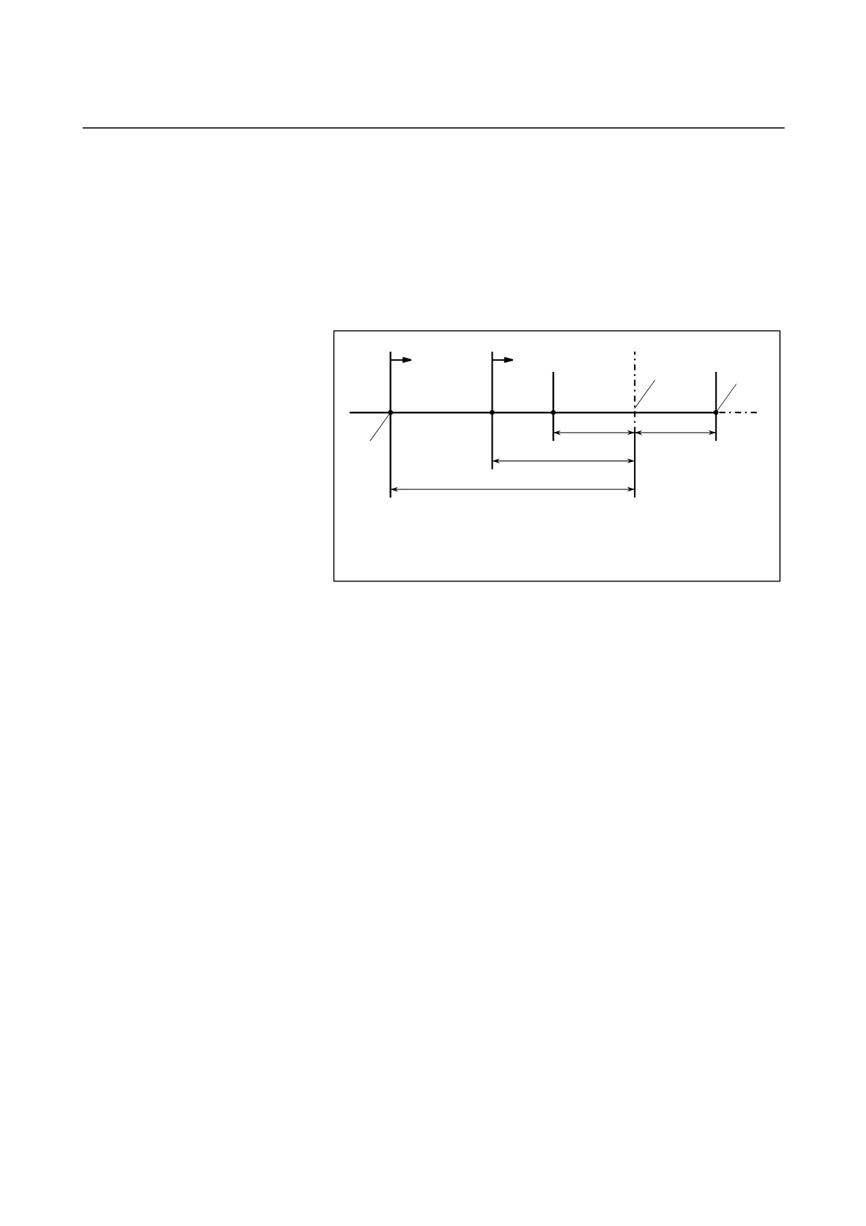
- Feedrate and alarm
The tool, when moving from the stating position toward the
measurement position predicted by xa or za in G36 or G37, is feed at
the rapid traverse rate across area A. Then the tool stops at point T
(xa-γ or za-γ) and moves at the measurement feedrate set by parameter
(No. 6241) across areas B, C, and D. If the approach end signal turns
on during movement across area B, alarm is generated. If the approach
end signal does not turn on before point V, and tool stops at point V
and alarm PS0080 is generated.
Predicted measurement position
FR
FP
U
V
X, Z
A
B
C
D
S (xs, zs)
T
ε
ε
Starting
position
γ
|xa-xs|. |za-zs|
U (xa, za)
FR : Rapid traverse rate
FP : Measurement feedrate (set by parameter(No.6241))
γ
: Parameters No.6251, No.6252
ε
: Parameters No.6254, No.6255
Fig. 5.5 (a) Feedrate and alarm
- 245 -
5.COMPENSATION FUNCTION
PROGRAMMING
B-64304EN-1/01
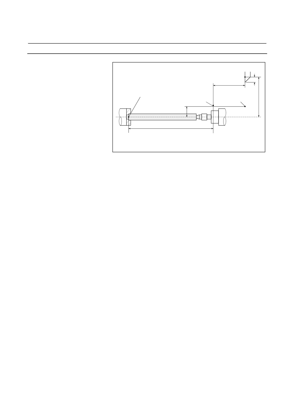
Example
Tool number T01
50
300
X-axis
Programmed zero point
measurement
position
380
Z-axis measurement position
100
800
Offset value
Offset value
(Before measurement)
(After measurement)
X
100.0
98.0
Z
0
4.0
G50 X760.0 Z1100.0 ;
Programming of absolute zero point
(Coordinate system setting)
S01 M03 T0101 ;
Specifies tool T1, offset number
1, and
spindle revolution
G36 X200.0 ;
Moves to the measurement position
If the tool has reached the measurement
position at X198.0
; since the correct
measurement position is 200 mm, the offset
value is altered by 198.0-200.0=-2.0mm.
G00 X204.0 ;
Refracts a little along the X axis.
G37 Z800.0 ;
Moves to the Z-axis measurement position.
If the tool has reached the measurement
position at X804.0, the offset value is altered
by 804.0-800.0=4.0mm.
T0101 ;
Further offsets by the difference.
The new offset value becomes valid when the
T code is specified again.
- 246 -
B-64304EN-1/01
PROGRAMMING
5.COMPENSATION FUNCTION
WARNING
1
Measurement speed(Fp), γ, and ε are set as parameters (Fp : No.6241, γ :
No.6251, ε : No.6254) by machine tool builder. ε must be positive numbers so that
γ>ε.
2
Cancel the tool nose radius compensation before G36, G37.
3
A delay or variation in detection of the measurement position arrival signal is 0 to 2
msec on the CNC side excluding the PMC side. Therefore, the measurement
error is the sum of 2 msec and a delay or variation (including a delay or variation on
the receiver side) in propagation of the measurement position arrival signal on the
PMC side, multiplied by the feedrate set in parameter No. 6241.
4
A delay or variation in time after detection of the measurement position arrival
signal until a feed stops is 0 to 8 msec. To calculate the amount of overrun,
further consider a delay in acceleration/deceleration, servo delay, and delay on the
PMC side.
5
When a manual movement is inserted into a movement at a measurement
feedrate, return the tool to the position before the inserted manual movement for
restart.
6
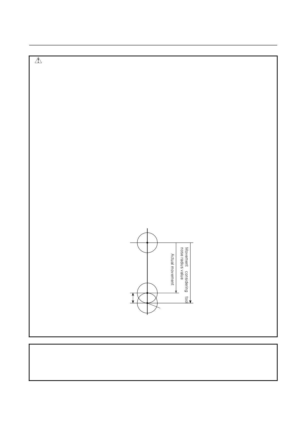
When tool nose radius compensation is enabled (bit 7 (NCR) of parameter No.
8136 is set to 0), the tool offset amount is calculated with considering the tool nose
radius value. Make sure that tool nose radius value is set correctly.
(Condition under which the tool-nose radius compensation is considered)
For the X-axis (first axis of the basic three axes) : TIP=0/5/7
For the Z-axis (third axis of the basic three axes) : TIP=0/6/8
For the Y-axis (second axis of the basic three axes) : TIP=0
A
B
Tool nose
radius
value
C
Measurement
position
The tool actually moves from point A to point B, but the tool offset value is
determined assuming that the tool moves to point C considering the tool nose
radius value.
NOTE
1 When there is no T code command before G36 or G37, alarm PS0081 is
generated.
2 When a T code is specified in the same block as G36 or G37, alarm PS0082 is
generated.
- 247 -
6. MEMORY OPERATION
USING Series 10/11 FORMAT
PROGRAMMING
B-64304EN-1/01
6
MEMORY OPERATION USING Series
10/11 FORMAT
By setting the setting-related parameter (bit 1 of parameter No. 0001),
a program created in the Series
10/11 program format can be
registered in memory for memory operation. Memory operation are
possible for the functions which use the same program format as that
for the Series 10/11 as well as for the following functions which use a
different program format:
•
Subprogram calling
•
Canned cycle
•
Multiple repetitive canned cycle
•
Canned cycle for drilling
NOTE
Memory operation are possible only for the
functions available in this CNC.
Chapter 6, "MEMORY OPERATION BY Series 10/11 FORMAT",
consists of the following sections:
6.1 ADDRESSES AND SPECIFIABLE VALUE RANGE FOR
Series 10/11 PROGRAM FORMAT
249
6.2 SUBPROGRAM CALLING
249
6.3 CANNED CYCLE
250
6.4 MULTIPLE REPETITIVE CANNED CYCLE
272
6.5 CANNED CYCLE FOR DRILLING
315
- 248 -

6.MEMORY OPERATION
B-64304EN-1/01
PROGRAMMING
USING Series 10/11 FORMAT
6.1
ADDRESSES AND SPECIFIABLE VALUE RANGE FOR
Series 10/11 PROGRAM FORMAT
Some addresses which cannot be used for the this CNC can be used in
the Series 10/11 program format. The specifiable value range for the
Series 10/11 program format is basically the same as that for the this
CNC. Sections II-6.2 to II-6.5 describe the addresses with a different
specifiable value range. If a value out of the specifiable value range is
specified, an alarm is issued.
6.2
SUBPROGRAM CALLING
Format
M98 Pxxxx Lyyyy ;
P : Subprogram number
L : Repetition count
Explanation
- Address
Address L cannot be used in this CNC tape format but can be used in
the Series 10/11 format.
- Subprogram number
The specifiable value range is the same as that for this CNC (1 to
9999).
If a value of more than four digits is specified, the last four digits are
assumed as the subprogram number.
- Repetition count
The repetition count L can be specified in the range from 1 to 9999. If
no repetition count is specified, 1 is assumed.
- 249 -
6. MEMORY OPERATION
USING Series 10/11 FORMAT
PROGRAMMING
B-64304EN-1/01
6.3
CANNED CYCLE
Explanation
There are three canned cycles : the outer diameter/internal diameter
cutting canned cycle (G90), the threading canned cycle (G92), and the
end face turning canned cycle (G94).
NOTE
1 Explanatory figures in this section use the ZX plane
as the selected plane, diameter programming for
the X-axis, and radius programming for the Z-axis.
When radius programming is used for the X-axis,
change U/2 to U and X/2 to X.
2 A canned cycle can be performed on any plane
(including parallel axes for plane definition).
When G code system A is used, however, U, V,
and W cannot be set as a parallel axis.
3 The direction of the length means the direction of
the first axis on the plane as follows:
ZX plane: Z-axis direction
YZ plane: Y-axis direction
XY plane: X-axis direction
4 The direction of the end face means the direction of
the second axis on the plane as follows:
ZX plane: X-axis direction
YZ plane: Z-axis direction
XY plane: Y-axis direction
- 250 -
6.MEMORY OPERATION
B-64304EN-1/01
PROGRAMMING
USING Series 10/11 FORMAT
6.3.1
Outer Diameter/Internal Diameter Cutting Cycle (G90)
This cycle performs straight or taper cutting in the direction of the
length.
6.3.1.1
Straight cutting cycle
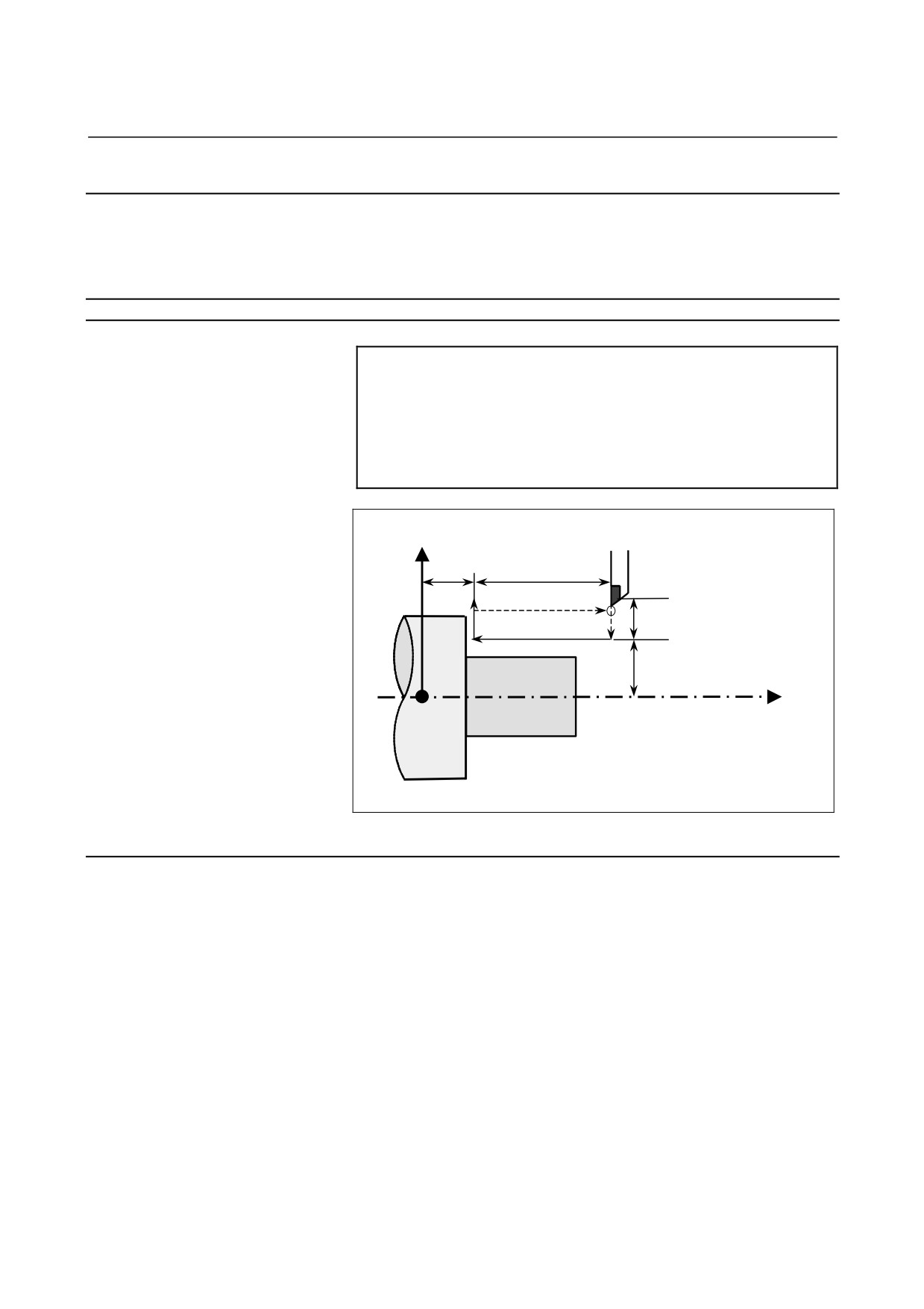
Format
G90X(U)_Z(W)_F_;
X_,Z_ : Coordinates of the cutting end point (point A' in the
figure below) in the direction of the length
U_,W_ : Travel distance to the cutting end point (point A' in
the figure below) in the direction of the length
F_
: Cutting feedrate
X axis
(R)
Rapid traverse
(F)
Cutting feed
Z
W
4(R)
A
3(F)
2(F)
1(R)
U/2
A’
X/2
Z axis
Fig. 6.3.1 (a) Straight cutting cycle
Explanation
- Operations
A straight cutting cycle performs four operations:
(1) Operation
1 moves the tool from the start point
(A) to the
specified coordinate of the second axis on the plane (specified
X-coordinate for the ZX plane) in rapid traverse.
(2) Operation 2 moves the tool to the specified coordinate of the first
axis on the plane (specified Z-coordinate for the ZX plane) in
cutting feed.
(The tool is moved to the cutting end point (A') in
the direction of the length.)
(3) Operation 3 moves the tool to the start coordinate of the second
axis on the plane (start X-coordinate for the ZX plane) in cutting
feed.
(4) Operation 4 moves the tool to the start coordinate of the first axis
on the plane
(start Z-coordinate for the ZX plane) in rapid
traverse.
(The tool returns to the start point (A).)
- 251 -
6. MEMORY OPERATION
USING Series 10/11 FORMAT
PROGRAMMING
B-64304EN-1/01
NOTE
In single block mode, operations 1, 2, 3 and 4 are
performed by pressing the cycle start button once.
- Canceling the mode
To cancel the canned cycle mode, specify a group 01 G code other
than G90, G92, or G94.
- 252 -
6.MEMORY OPERATION
B-64304EN-1/01
PROGRAMMING
USING Series 10/11 FORMAT
6.3.1.2
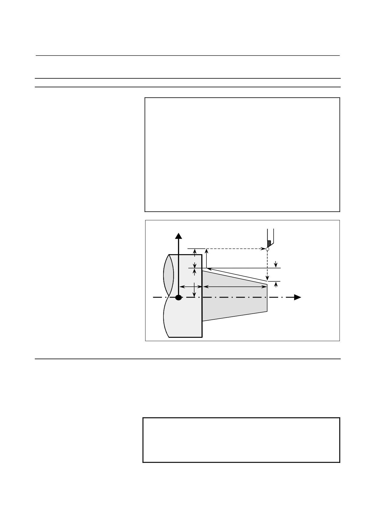
Taper cutting cycle
Format
ZpXp-plane
G90 X(U)_ Z(W)_ I_ F_ ;
YpZp-plane
G90 Y(V)_ Z(W)_ K_ F_ ;
XpYp-plane
G90 X(U)_ Y(V)_ J_ F_ ;
X_,Y_,Z_
: Coordinates of the cutting end point (point A' in
the figure below) in the direction of the length
U_,V_,W_ : Travel distance to the cutting end point (point A'
in the figure below) in the direction of the length
I_,J_,K_
: Taper amount (I in the figure below)
F_
: Cutting feedrate
X axis
(R)
Rapid traverse
(F)
Cutting feed
4
(R)
A
3
(F)
U/2
1
(R)
A’
2
(F)
I
X/2
W
Z
Z axis
Fig. 6.3.1 (b) Taper cutting cycle
Explanation
Address I, J, or K for specifying a taper varies with the plane selected.
The figure of a taper is determined by the coordinates of the cutting
end point (A') in the direction of the length and the sign of the taper
amount (address I, J, or K). For the cycle in the figure above, a
minus sign is added to the taper amount.
NOTE
The increment system of address I, J, or K for
specifying a taper depends on the increment
system for the reference axis. Specify a radius
value at I, J, or K.
- 253 -