FANUC Series 0i-MODEL D, FANUC Series 0i Mate-MODEL D. MAINTENANCE MANUAL - page 19
B-64305EN/03
APPENDIX
D.MEMORY CARD SLOT
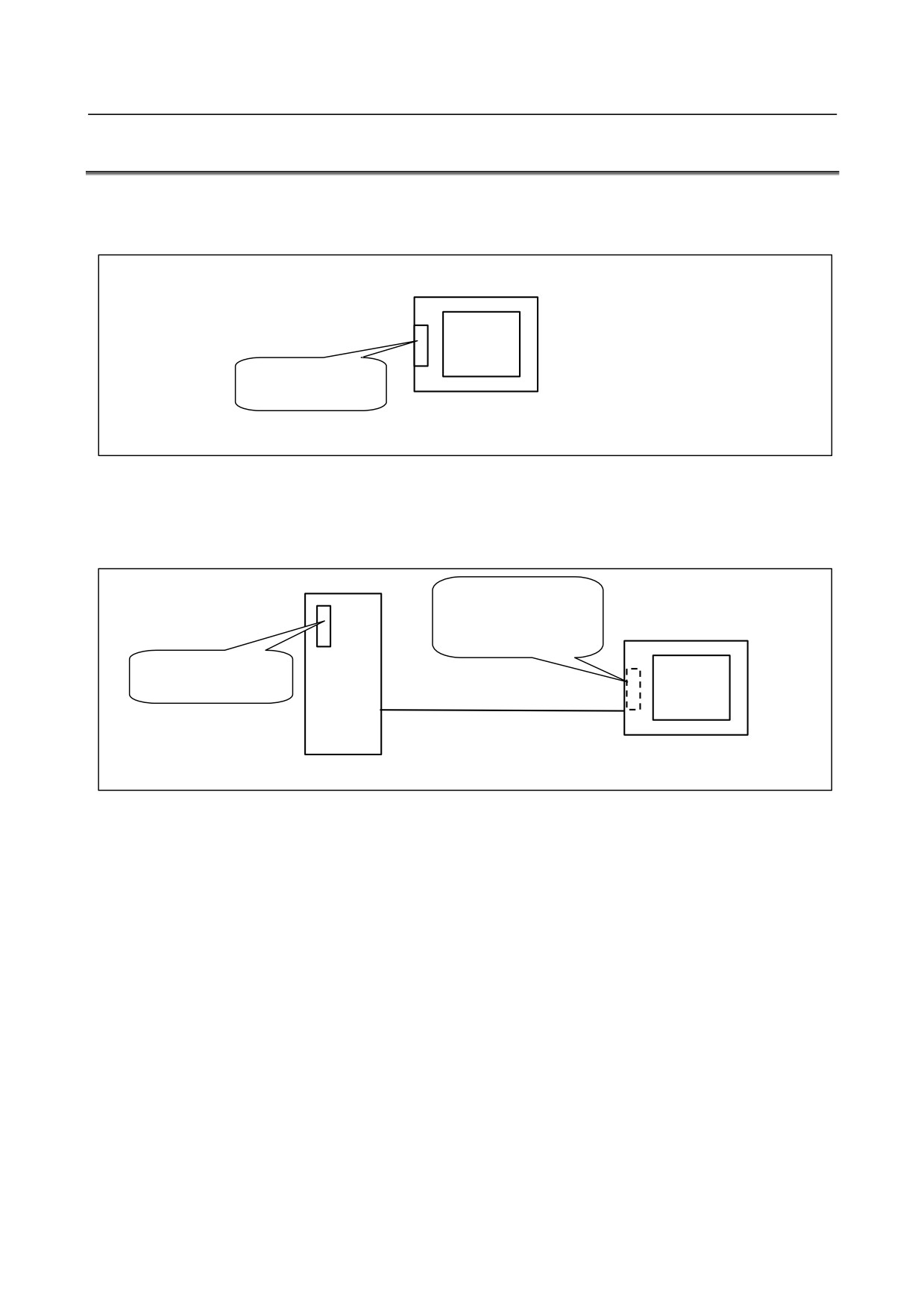
D.3 HARDWARE CONFIGURATION
Type 1
LCD-mounted type
Card slot on
display unit side
Control unit (LCD-mounted type)
Type 3
Stand-alone type
When the HSSB interface on the main board is used to connect the PANEL i or personal computer
(Whe PANEL i is
used)
Card slot on display
unit side
Card slot on control
unit side
Optical cable
HSSB
interface
PANEL i or personal Computer
Control unit (stand-alone type)
- 527 -
E.LED DISPLAY
APPENDIX
B-64305EN/03
E LED DISPLAY
Appendix E, "LED DISPLAY", consists of the following sections:
E.1 OVERIVIEW
528
E.2
7-SEGMENT LED INDICATIONS (TURNED ON)
528
E.3
7-SEGMENT LED INDICATIONS (BLINKING)
530
E.1 OVERVIEW
On the CNC, a 7-segment LED is installed.
The 7-segment LED indication changes according to the operating status of the CNC.
The 7-segment LED indications provided after the power is turned on until the CNC
is ready for
operation and when system errors occur are described below.
E.2
7-SEGMENT LED INDICATIONS (TURNED ON)
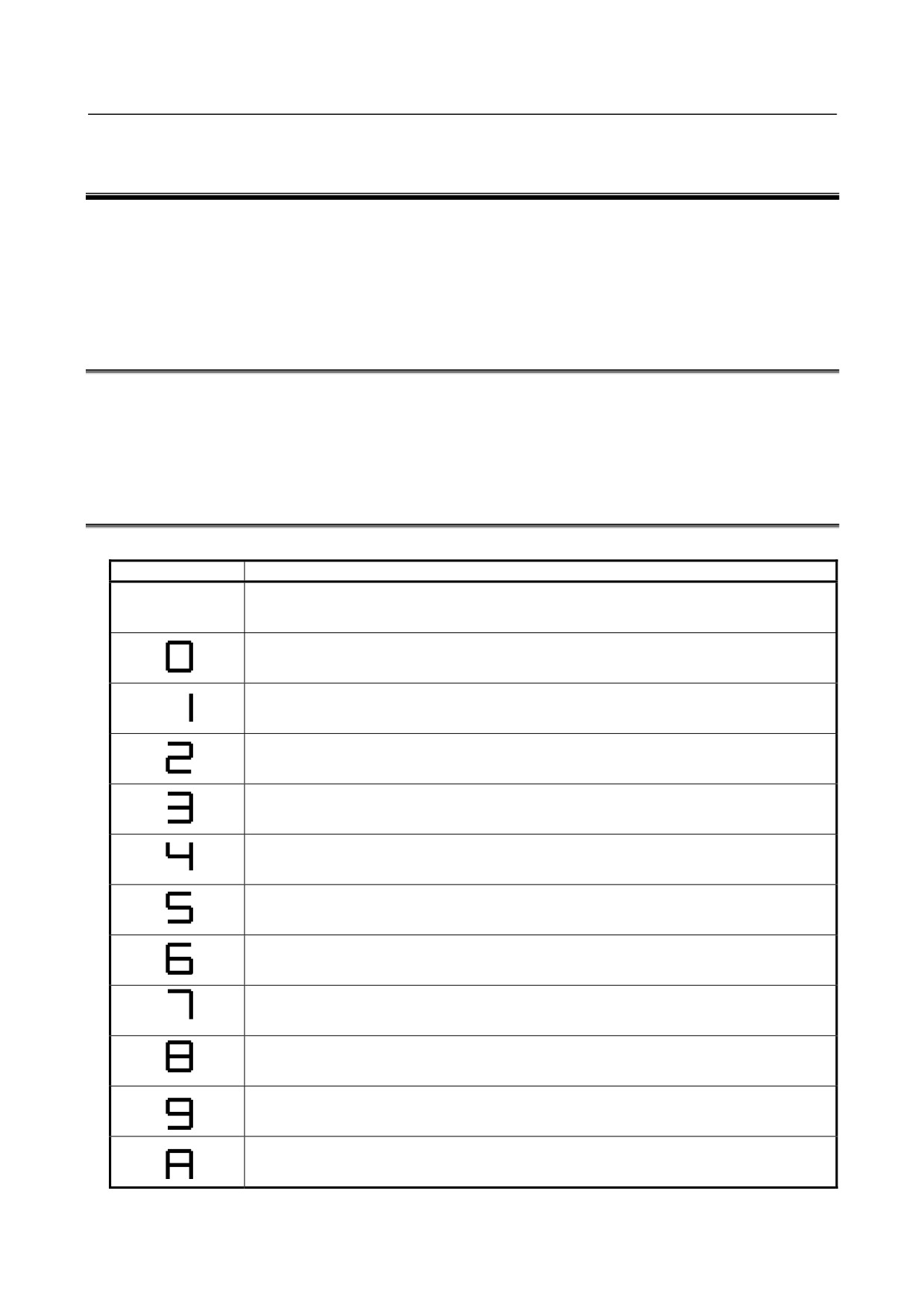
Table E.2 (a) LED display from power-on to the operable state
LED Display
Meaning
Power not turned on (power-off state)
Initialization completed and ready for operation
CPU started up
(BOOT system)
Initialization of G/A
(BOOT system)
Initialization of various functions
Task initialization
System configuration parameter check
Additional board waiting 2
Installation of various drivers
All files cleared
Title display
System ROM test
State where the CPU is not started after the power is turned on
(BOOT system)
BOOT system ended, NC system started
(BOOT system)
FROM initialization
- 528 -
B-64305EN/03
APPENDIX
E.LED DISPLAY
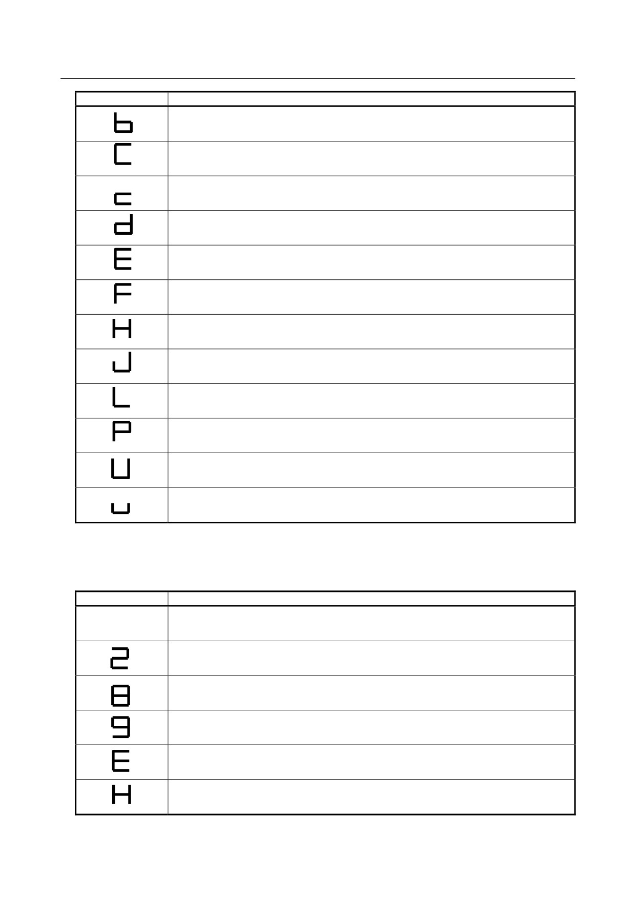
LED Display
Meaning
Loading of embedded software
Loading of software for optional boards
IPL monitoring in progress
DRAM test error
(BOOT system, NC system)
BOOT system error
(BOOT system)
File cleared
Optional board waiting 1
Loading of basic system software
(BOOT system)
Optional board waiting 3
Optional board waiting 4
Final system operation check
Display unit initialization
(BOOT system)
FROM initialization
(BOOT system)
BOOT monitoring in progress
(BOOT system)
If processing stops during startup due to a CNC error, and the system alarm screen is not displayed, take
corrective action referring to Table E.2 (b).
Table E.2 (b) Faulty Regions and Check Items If Processing Stops during Startup
LED display
Faulty region and check item
The power supply (24V) or the power module may be faulty.
The main board or the display unit may be faulty.
The main board may be faulty.
The main board may be faulty.
The main board (CPU circuit) may be faulty.
The SRAM/FROM module or the main board may be faulty.
- 529 -
E.LED DISPLAY
APPENDIX
B-64305EN/03
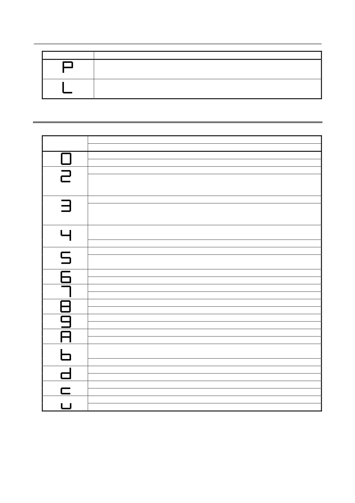
LED display
Faulty region and check item
The main board or the display unit may be faulty.
The main board (CPU circuit) may be faulty.
E.3
7-SEGMENT LED INDICATIONS (BLINKING)
Table E.3 (a) LED display during occurrence of a system error
Meaning
LED Display
Faulty region and check item
ROM PARITY error
The SRAM/FROM module may be faulty.
An FROM file for program memory cannot be created.
The state of the file for program memory on the FROM is checked with the BOOT system.
Rearrange the FROM.
Check the FROM size.
Software-detected system alarm
If it is generated during startup: Use BOOT to check the state of the built-in software in FROM,
and check the size of DRAM.
In other cases: Check the error on the alarm screen and take corrective action.
The DRAM/SRAM/FROM ID is invalid.
(BOOT system, NC system)
The main board or the SRAM/FROM module may be faulty.
A servo CPU timeout occurred.
Check the state of servo software on the FROM with the BOOT system.
The servo card may be faulty.
An error occurred when embedded software is incorporated.
Check the state of embedded software on the FROM with the BOOT system.
The display unit cannot be recognized.
The display unit may be faulty.
Hardware-detected system alarm
Check the error on the alarm screen and take corrective action.
Software for optional boards could not be loaded.
Check the state of software for optional boards on the FROM with the BOOT system.
An error occurred in waiting for an optional board.
The option board or the PMC module may be faulty.
The BOOT FROM was updated.
(BOOT system)
Turn on the power again.
DRAM test error
The main board may be faulty.
The ID of the display unit is invalid.
Check the display unit.
The ID of the BASIC system software does not math that of the hardware.
Check the combination of the BASIC system software and the hardware
- 530 -
F.MAINTENANCE OF OPEN
B-64305EN/03
APPENDIX
CNC (BOOT-UP AND IPL)
F MAINTENANCE OF OPEN CNC (BOOT-UP
AND IPL)
Appendix F, "MAINTENANCE OF OPEN CNC (BOOT-UP AND IPL)", consists of the following
sections:
F.1 OVERVIEW
531
F.2 CHANGING START SEQUENCES
532
F.3 EXPLANATION OF SCREENS
533
F.3.1
BOOT Screen
533
F.3.2
IPL Screen
536
F.4 OTHER SCREENS
537
F.4.1
CNC Alarm Screen
537
F.4.2
Status Screen
538
F.4.3
Option Setting Screen
538
F.1
OVERVIEW
When the stand-alone type CNC is connected to the PANEL i or personal computer via HSSB, you can
perform maintenance of the CNC using Ncboot32.exe.
NOTE
When the LCD-mounted type CNC is connected to the PC over Ethernet, use
the standard LCD/MDI for the maintenance of the CNC.
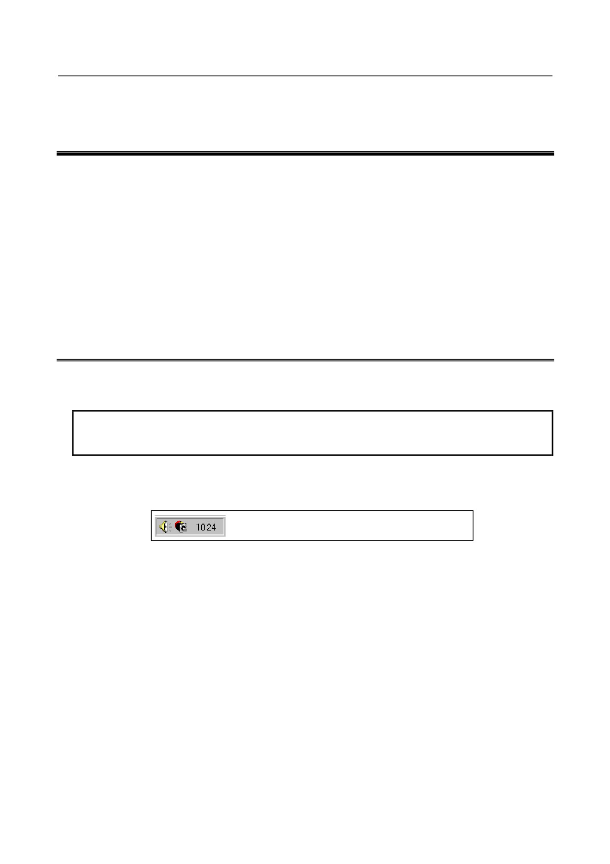
Ncboot32.exe is installed simultaneously when the HSSB driver is installed on the personal computer. It
automatically starts up at the start-up of Windows and resides in the system tray.
(Icon at the center)
Ncboot32.exe provides the following functions:
• BOOT screen (for CNC system data maintenance, SRAM backup, and so forth)
• IPL screen (for clearing SRAM, and so forth)
• Display of the CNC power-on screen
• Display of CNC alarm screen
• Re-connection in case of the occurrence of a communication error
• Start of a registered application program
• Automatic call of the BOOT/IPL screen at the next start-up of the CNC
Supplementary 1: Multi-connection
Ncboot32.exe supports HSSB multi-connection. The CNCs connected by HSSB are managed as nodes.
The BOOT, IPL, and system alarm screens are displayed in windows that are opened independently for
each node.
Supplementary 2: Termination method
Normally, Ncboot32.exe need not be terminated. If you need to terminate it, however, see the "System
tray" explanation, below: Display the popup menu and select "End".
When the Ncboot32.exe window is open, End cannot be selected.
- 531 -
F. MAINTENANCE OF OPEN
CNC (BOOT-UP AND IPL)
APPENDIX
B-64305EN/03
System tray
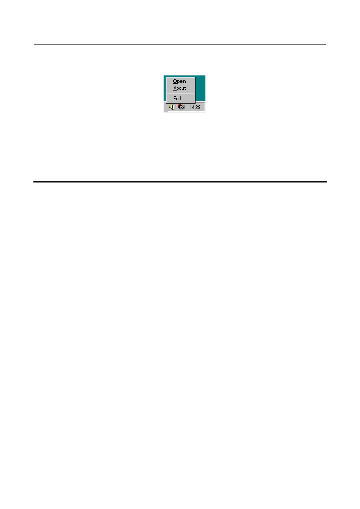
Right-click the icon in the system tray, and the popup menu, shown below, appears.
Selecting [Open] causes the status screen to open.
Selecting [About] causes the version information dialog box to appear.
Selecting [End] causes Ncboot32.exe to terminate.
Double-clicking the icon in the system tray causes Open in the menu to be automatically selected.
F.2
CHANGING START SEQUENCES
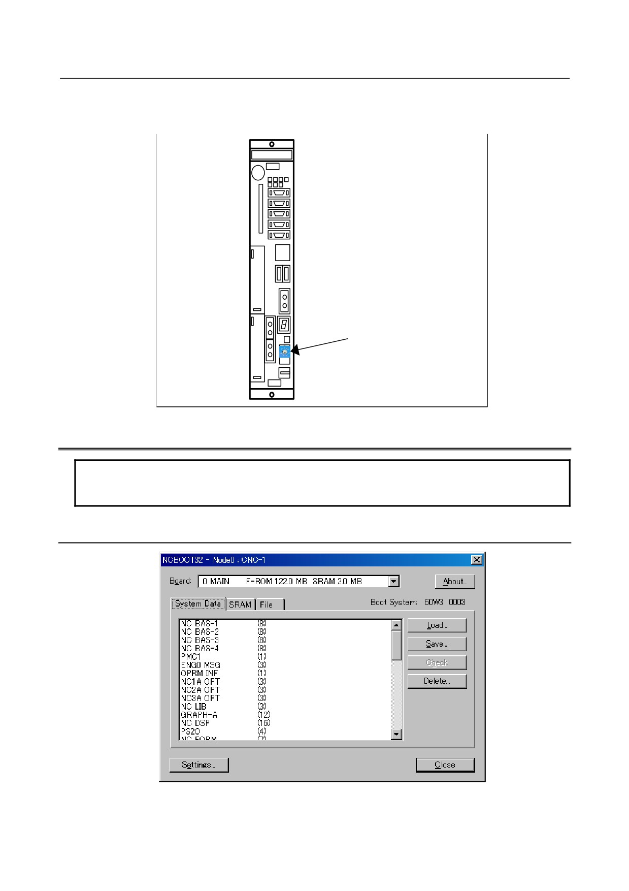
By setting the rotary switch provided on the main board of the CNC main unit to the F position, you can
perform maintenance work using the BOOT and IPL screens.
Start-up sequence for the maintenance work (rotary switch position: F)
1.
Wait until communication with the CNC is established.
2.
Display the BOOT screen.
3.
Display the IPL screen.
4.
Display the CNC power-on screen.
5.
Start FOCAS2.
6.
Start a registered application program (such as CNC screen display function).
7.
Perform monitoring for communication errors and CNC system alarms.
Start-up sequence for normal operation (rotary switch position:
0)
1.
Wait until communication with the CNC is established.
2.
Start FOCAS2.
3.
Start a registered application program (such as CNC screen display function).
4.
Perform monitoring for communication errors and CNC system alarms.
Asynchronous start-up sequence (rotary switch position: E)
1.
The CNC starts without waiting for communication to be established.
2.
After communication is established, the personal computer performs initialization described below.
3.
Start FOCAS2.
4.
Start a registered application program (such as CNC screen display function).
5.
Perform monitoring for communication errors and CNC system alarms.
- 532 -
F.MAINTENANCE OF OPEN
B-64305EN/03
APPENDIX
CNC (BOOT-UP AND IPL)
• Location of rotary switch
• Stand-alone type Series 0i-D
Rotary switch
F.3
EXPLANATION OF SCREENS
NOTE
To open each screen of Ncboot32.exe, you are recommended to use either the
mouse or touch panel.
F.3.1
BOOT Screen
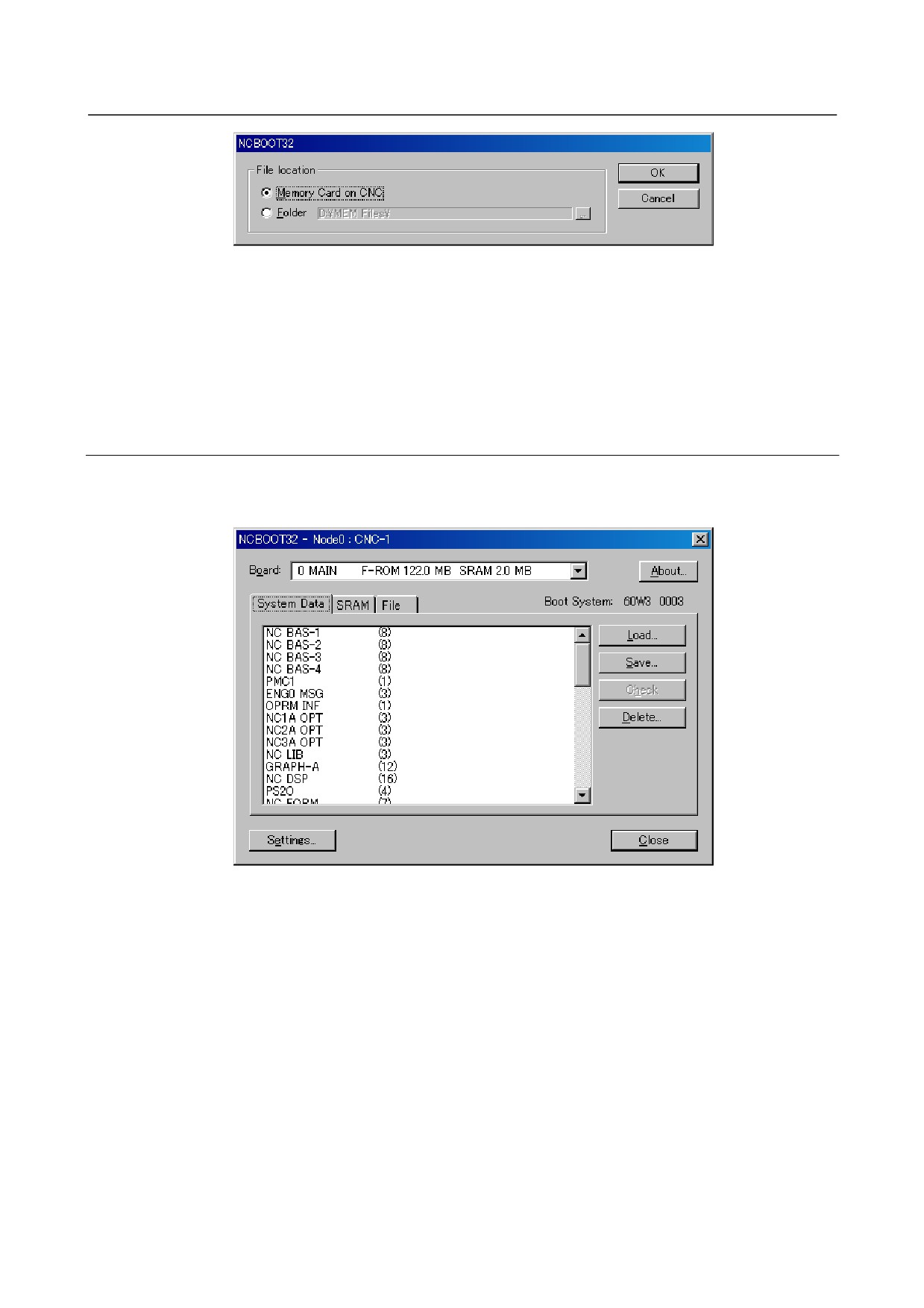
The area where the file is to be placed can be changed by using the [Setting...] button.
- 533 -
F. MAINTENANCE OF OPEN
CNC (BOOT-UP AND IPL)
APPENDIX
B-64305EN/03
Select the memory card on the CNC or a personal computer folder. The file location may be changed at
any time.
"Memory Card on CNC":
Specify the memory card slot of the CNC.
"Folder":
Specify a folder on the PC.
To use the memory card slot beside PANEL i, select "Folder" and specify the drive name given to the
memory card by Windows.
F.3.1.1 System data manipulation
The following screen is used for manipulating system data (including control software and ladder
programs) on the CNC.
[Load...] opens the file selection screen. Specify a file to be loaded.
[Save] saves the selected system data on the CNC in a file.
[Check] checks the selected system data on the CNC.
[Delete] deletes the selected system data on the CNC.
- 534 -
F.MAINTENANCE OF OPEN
B-64305EN/03
APPENDIX
CNC (BOOT-UP AND IPL)
F.3.1.2 SRAM operation
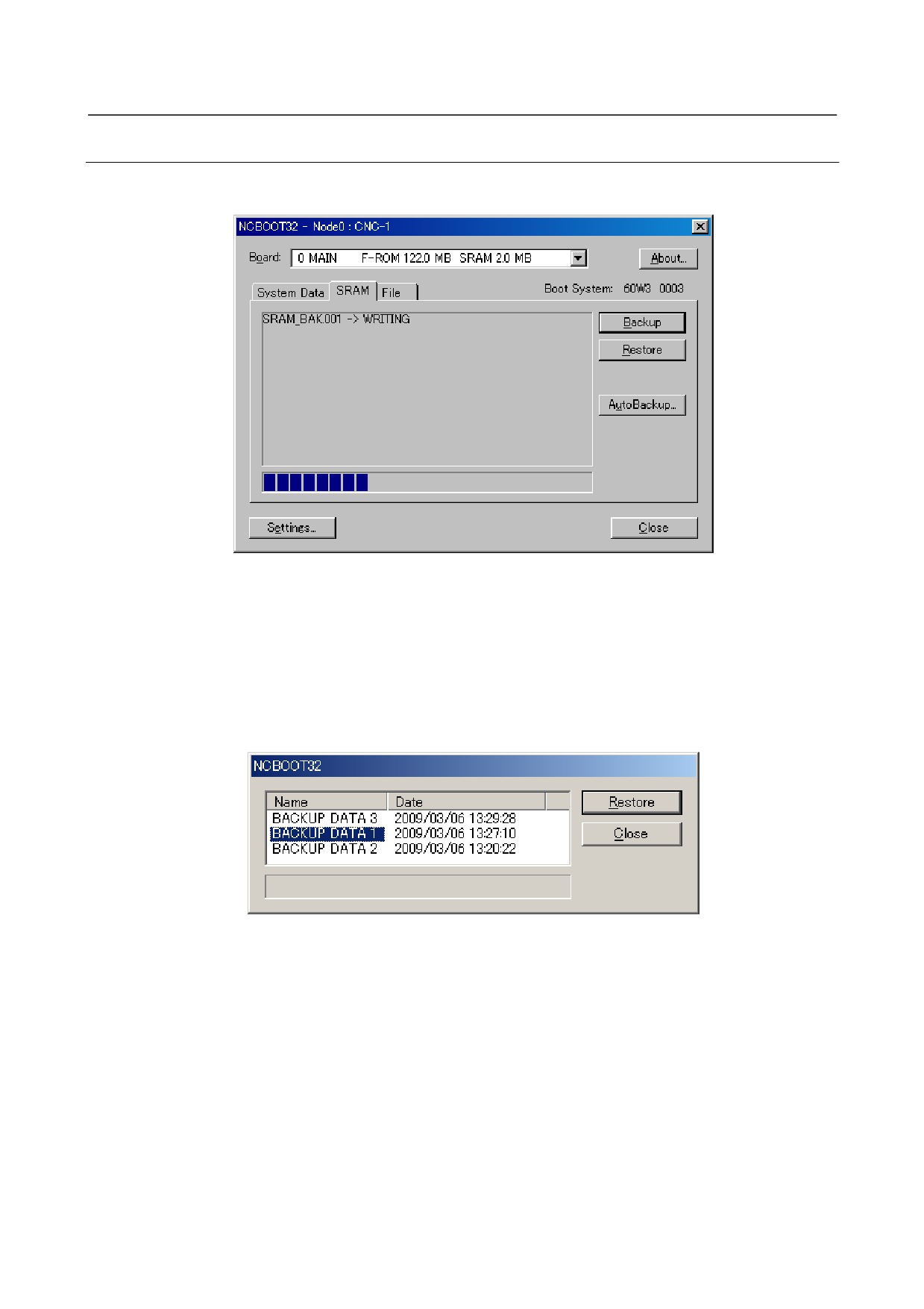
This screen is used to store and restore CNC SRAM data.
[Backup]:
Saves SRAM data to a file.
[Restore]:
Restore SRAM data from a file.
The progress of the operation is indicated in the lower part of the screen. The name of the backup file is
automatically determined according to the SRAM size and cannot be changed.
The CNC has the automatic data backup (option) of automatically saving the data of SRAM in FROM.
The personal computer can restore the data that was saved automatically to SRAM. Press the
[AutoBackup...] button to display the following screen.
Select a saved image under "Name" and press the [Restore] button to restore the SRAM data of the
CNC.
- 535 -
F. MAINTENANCE OF OPEN
CNC (BOOT-UP AND IPL)
APPENDIX
B-64305EN/03
F.3.1.3 File operation
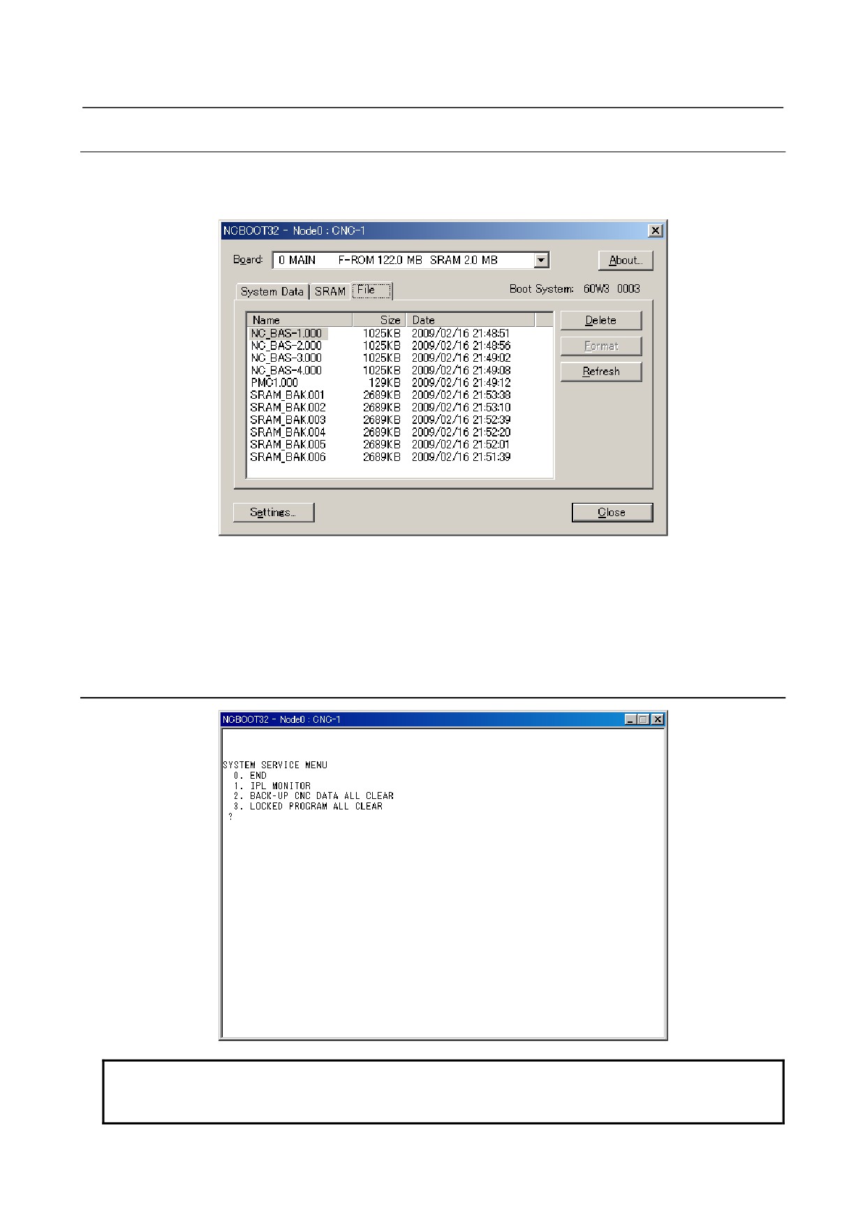
The following screen is used for operating files on a memory card in the CNC or in a folder of the
personal computer.
[Delete]
deletes a selected file.
[Format]
formats the memory card. This button is valid when the memory card is selected by
[Setting...]
[Refresh]
updates the file list to the latest state. After changing memory cards or floppy disks, click
this button.
F.3.2
IPL Screen
NOTE
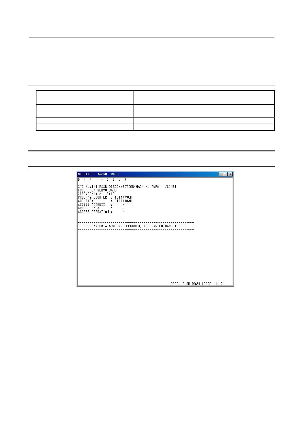
The contents of the IPL screen vary depending on the CNC model. Follow the
instructions displayed in the menu.
- 536 -
F.MAINTENANCE OF OPEN
B-64305EN/03
APPENDIX
CNC (BOOT-UP AND IPL)
The CNC allows functions to be performed according to the key status set at power-on.
The open CNC does not allow this operation. On the IPL screen, however, equivalent functions can be
executed.
For details of the menu on the IPL screen and supported functions, see the table given in Section F.3.2.1.
F.3.2.1 Functions on the IPL screen
Corresponding MDI key operation at power-on
Title on IPL screen
(Operation with a standard CNC)
0. EXIT
1. IPL MONITOR
<-> + <.> (Start-up of the IPL monitor)
2. BACK-UP CNC DATA ALL CLEAR
<DELETE> + <RESET> (Memory all clear)
3. LOCKED PROGRAM ALL CLEAR
<M> + <0> (The C language executor is not temporarily started.)
F.4
OTHER SCREENS
F.4.1
CNC Alarm Screen
This screen appears when a system alarm is issued in the CNC. (The above screen is an example. The
displayed information varies depending on the system alarm issued in the CNC.)
- 537 -
F. MAINTENANCE OF OPEN
CNC (BOOT-UP AND IPL)
APPENDIX
B-64305EN/03
F.4.2
Status Screen
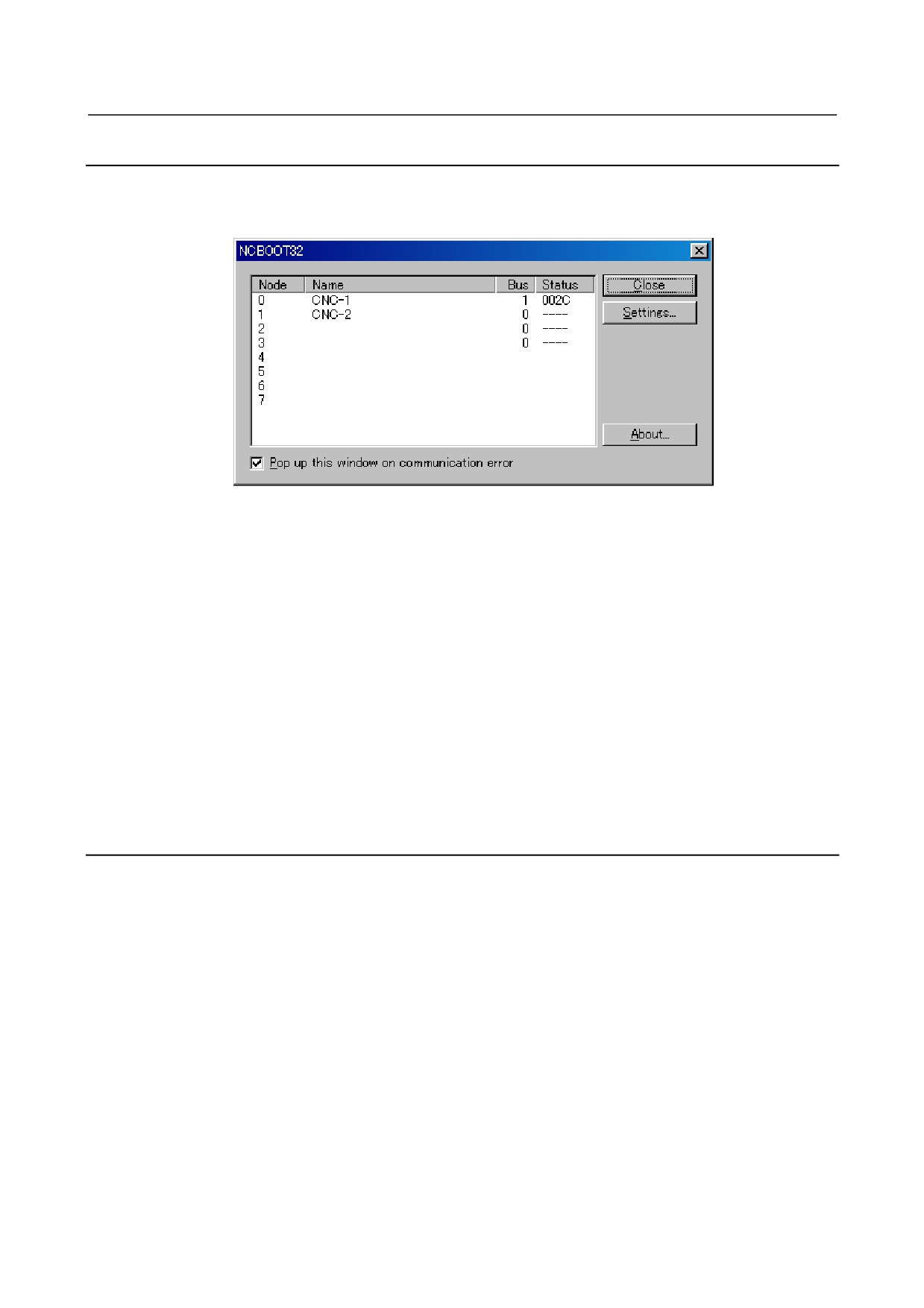
To open the status screen, double-click the icon in the system tray. Alternatively, in the menu popped
up by right-clicking, click Open.
Node: Node number
Name: Node name. (Define the node name in advance by using the HSSB applet on the control panel.)
Bus:
Hardware communication status (0: Communication error, 1: Communication established)
Status:
Status (in hexadecimal)
Bit 2:
End of BOOT processing
Bit 3:
End of IPL processing
Bit 4:
Rotary switch position 0
Bit 5:
Display of 30 lines on IPL/system alarm screen
Bit 8:
CNC system alarm
Pop up this window on communication error: By checking this item, this screen is opened automatically
when a communication error occurs.
Clicking the [Close] button closes the screen.
Clicking the [Setting...] button opens the option setting screen.
Clicking the [About...] button opens the version information screen.
F.4.3
Option Setting Screen
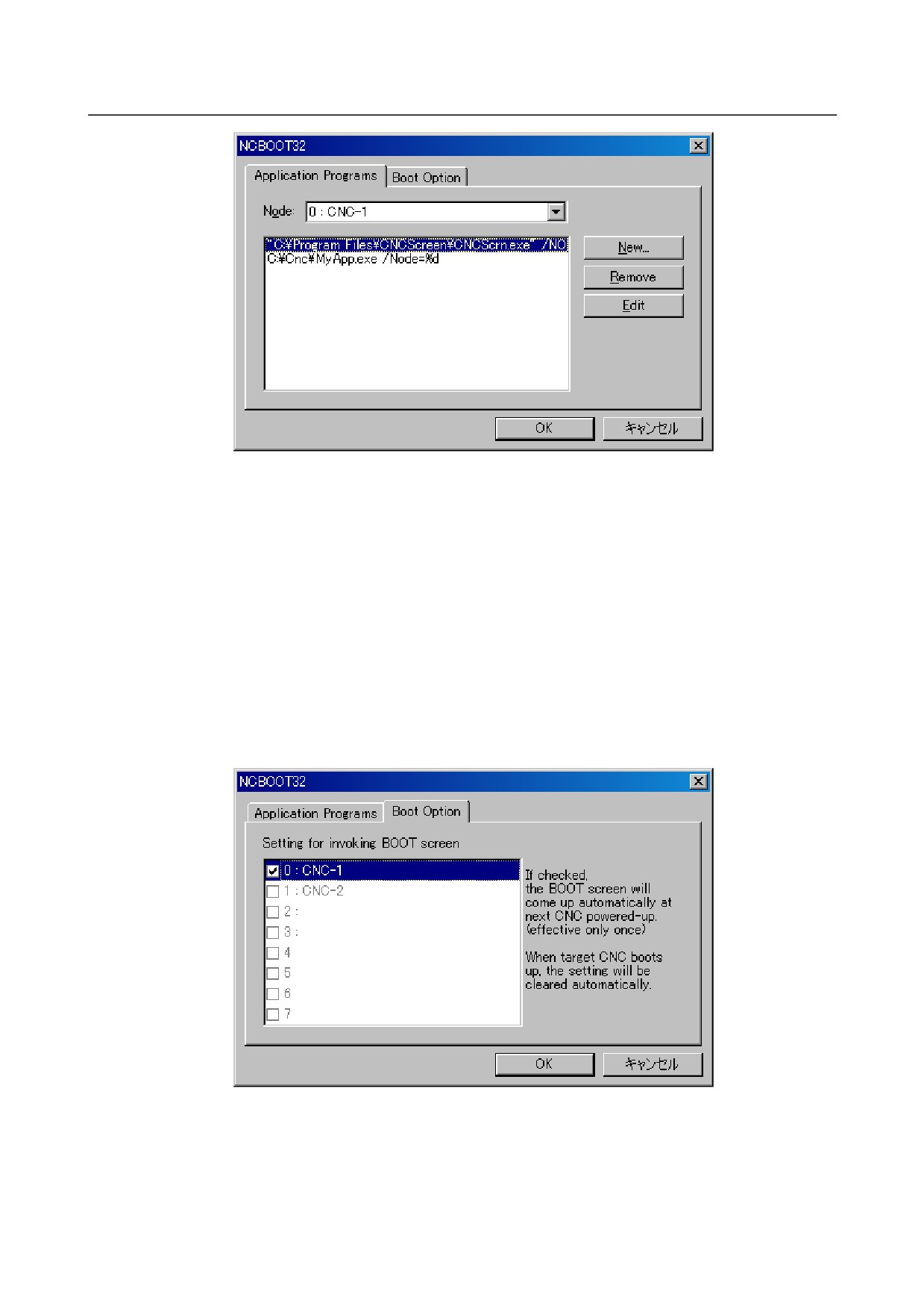
On the option setting screen, application programs can be registered.
Any programs for use with FOCAS2 will not run unless they are started after communication
establishment with CNC. By registering these programs in Ncboot32.exe, they can be executed in
synchronization with the start of FOCAS2. (Such as CNC screen display function)
Clicking the [Settings...] button on the status screen causes the option setting screen to open. On the
option setting screen, an application must be registered with each node that requires it. In addition, it is
possible to set the display of the BOOT/IPL screen during the next startup of the CNC.
- 538 -
F.MAINTENANCE OF OPEN
B-64305EN/03
APPENDIX
CNC (BOOT-UP AND IPL)
[Node]
selects a node. In the list box in the center of the screen, the programs registered for the
selected node are displayed.
[New...]
registers a new program. When a blank character is included in the path, it is enclosed
with double quotation marks.
[Remove]
deletes a selected line.
[Edit]
allows editing of a selected line. This button is used to edit arguments. The character
string %d in the command line is replaced by a node number. To represent % itself,
describe %%.
Example: To start the CNC screen display function after FOCAS2 starts at that node, code the following:
“C:\Program Files\CNCScreen\CNCScrn.exe” /Node=%d
To set the display of the BOOT/IPL screen during the next startup of the CNC, select the "Boot Option"
tab on the option setting screen.
If a CNC that is not grayed out is checked, the BOOT/IPL screen appears during the next startup of the
CNC, regardless of the setting of the rotary switch on the CNC side. This display setting is enabled only
once and automatically cleared by Ncboot32.exe.
- 539 -
G.IPL MONITOR
APPENDIX
B-64305EN/03
G IPL MONITOR
Appendix G, "IPL MONITOR", consists of the following sections:
G.1 OVERVIEW
540
G.2 STARTING OF THE IPL MONITOR
540
G.3 IPL MENU
540
G.1 OVERVIEW
With the IPL monitor, the following operations can be performed:
1)
Clearing of individual files
CNC parameters, tool compensation data, and so forth can be cleared.
2)
Output of system alarm information
System alarm information that is stored in history information can be output to the memory card.
WARNING
1 From the IPL monitor menu, do not select an item other than the items listed
below.
The other items represent functions for FANUC service.
0. END IPL
3. CLEAR FILE
5. SYSTEM ALARM UTILITY
2 When an individual file is cleared, all data stored in the file is cleared and
initialized. So, before clearing an individual file, back up the data of the file as
needed.
3 If a system label error has occurred, perform a clear operation according to
Appendix H, "MEMORY CLEAR", instead of clearing of an individual file.
G.2 STARTING OF THE IPL MONITOR
The IPL monitor can be started according to the procedure below.
LCD-mounted type
<1> Turn on the power by pressing the MDI keys [.] and [-] simultaneously.
<2> The IPL monitor screen is displayed.
Stand-alone type
<1> Start NCBOOT32.
<2> Select "1. IPL MONITOR" on the IPL screen.
<3> The IPL monitor screen is displayed.
For details, see Appendix F, "MAINTENANCE OF OPEN CNC (BOOT-UP AND IPL)".
- 540 -
B-64305EN/03
APPENDIX
G.IPL MONITOR
G.3 IPL MENU
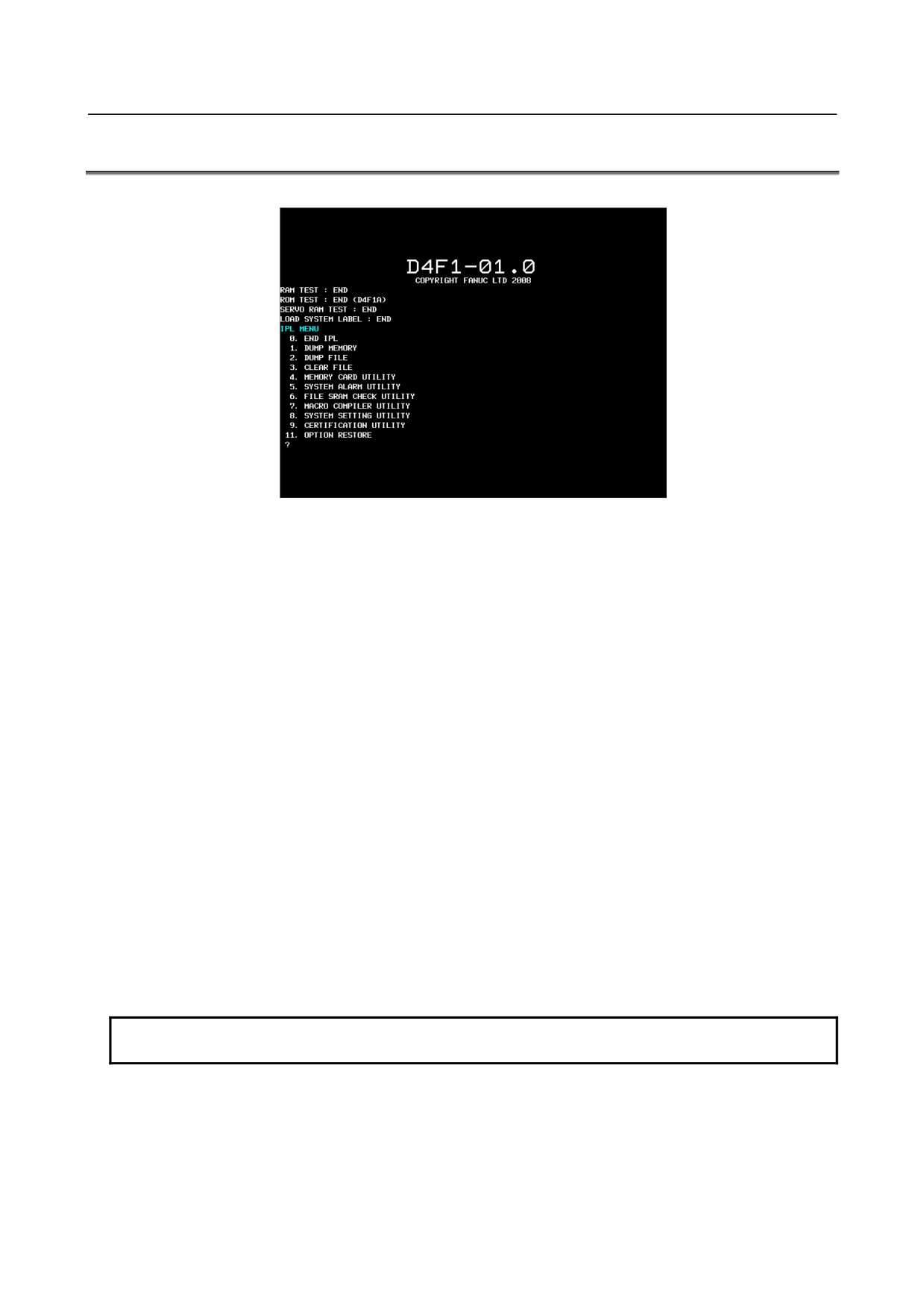
When the IPL monitor is started, the following screen is displayed.
Enter a menu item number by using the corresponding MDI key.
One of the following menu items can be selected:
0 : END IPL
3 : CLEAR FILE
5 : SYSTEM ALARM UTILITY
END IPL
This menu item ends the IPL monitor and starts the CNC.
CLEAR FILE
This menu item clears and initializes displayed individual files.
1 : All files except option parameter files
2 : CNC parameter files
3 : Tool compensation data
Tool compensation memory A and C, tool nose radius compensation data (including virtual tool tip
direction),
Y-axis offset data, and so forth
4 : Program storage files
5 : PMC parameter files
7 : Custom macro files
Macro variables, macro variable names
8 : Macro executor files
P code variables
9 : Touch panel data files
NOTE
The displayed individual file items vary, depending on the system configuration.
- 541 -
G.IPL MONITOR
APPENDIX
B-64305EN/03
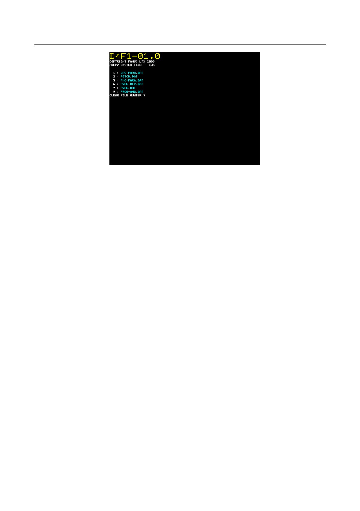
A file can be cleared according to the following procedure:
<1> Enter the number of a file to be cleared.
<2> The IPL monitor displays "CLEAR FILE OK ? (NO=0,YES=1)". Enter "1" to clear the file. To
cancel the clearing of the file, enter "0".
<3> When "1" is entered, the specified file is cleared then the menu above is displayed again.
<4> To clear an additional file, repeat steps <1> through <3>.
To quit, enter "0".
SYSTEM ALARM UTILITY
System alarm information can be output to the memory card.
For details, see Section
10.25, "SYSTEM ALARMS" in Chapter
10, "TROUBLESHOOTING
PROCEDURE".
- 542 -
B-64305EN/03
APPENDIX
H.MEMORY CLEAR
H MEMORY CLEAR
Appendix H, "MEMORY CLEAR", consists of the following sections:
H.1 OVERVIEW
543
H.2 OPERATION METHOD
543
H.3 DATA TYPES TO BE CLEARED
544
H.1 OVERVIEW
If an unexpected error occurs, such as the "SYSTEM LABEL CHECK ERROR" at system startup or the
"SYSTEM ALARM", which may be generated suddenly, this function can start up the CNC system in its
initial state to return the system to the state in which restoration work can be performed, by clearing all
data stored in CNC memory.
H.2 OPERATION METHOD
1. Starting method
<1> For LCD-mounted type
When turning the power ON to the CNC, turn the power ON while pressing the MID keys
and
at the same time and holding them down. Keep holding them down until
the memory all clear approval screen is displayed.
<2> For stand-alone type
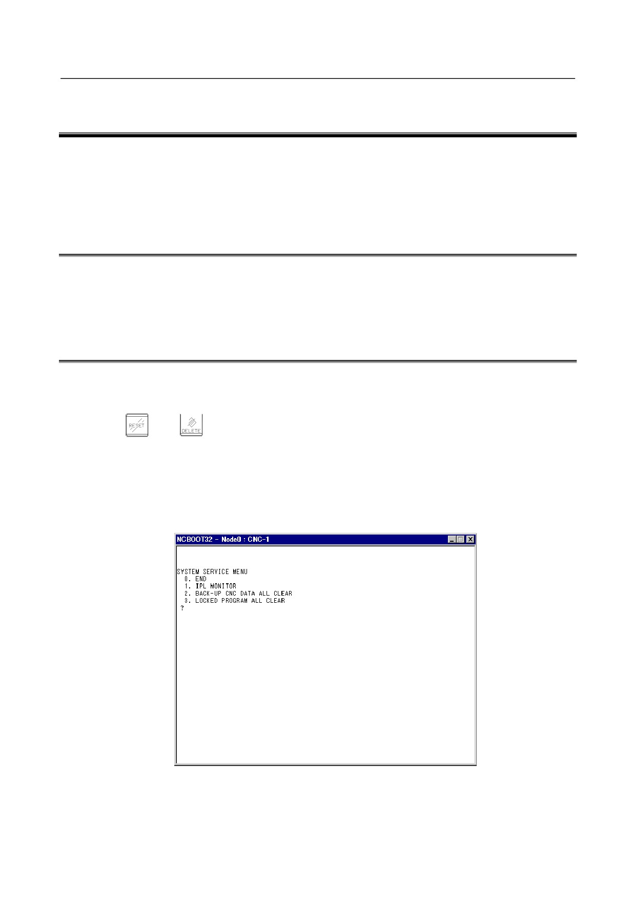
Use the NC BOOT32 function to display the IPL menu.
From the IPL menu, select "2. BACK-UP CNC DATA ALL CLEAR".
For details, see Appendix F, "MAINTENANCE OF OPEN CNC (BOOT-UP AND IPL)".
2. Memory all clear approval screen
Performing the operation in 1. causes the following screen to be displayed, asking you whether to
execute all clear.
- 543 -

H.MEMORY CLEAR
APPENDIX
B-64305EN/03
Memory All Clear Approval Screen
From the screen shown above, select between the following operation and execute it:
-
If you do not want to execute memory all clear, press the numeric key "0". All clear will be
canceled.
-
To execute memory all clear, press the numeric key "1". All clear will be executed.
WARNING
1 When this operation is performed, the CNC system enters a state (initial state) in
which it can start up by itself. To restore various function operations, therefore,
you must reconfigure cleared data.
2 This operation can be performed only by personnel who have been trained in
maintenance and safety.
H.3 DATA TYPES TO BE CLEARED
The various data types to be cleared by this operation are as follows:
Data type
Data area
System label
SRAM
Data related to C language executor
SRAM
(such as SRAM disk data)
Data related to macro executor
SRAM
(such as P code variables, extended P code variables, user file data)
NC parameters
SRAM
Pitch error compensation data
SRAM
Custom macro variables, variable name
SRAM
Data related to PMC
SRAM
(such as parameters, KEEP relay value)
Data related to part program
SRAM/
(such as program main body)
FROM
Tool offset data
SRAM
Workpiece coordinate system addition data (M series)
SRAM
(Workpiece coordinate system data is included in NC parameters.)
Tool life management data
SRAM
System alarm history data
SRAM
Software operator’s panel data
SRAM
- 544 -
B-64305EN/03
APPENDIX
H.MEMORY CLEAR
Data type
Data area
Periodic maintenance data
SRAM
Data related to Fast Data Server / Fast Ethernet (such as parameters)
SRAM
Operation history data
SRAM
Bi-directional pitch error compensation data
SRAM
Touch panel data
SRAM
PRFIBUS master/slave function data
SRAM
Rigid tapping retraction data (M series)
SRAM
Y-axis offset data (T series)
SRAM
Tool nose radius compensation value data (T series)
SRAM
Cutter compensation value data (M series)
SRAM
Data of interference check for each path (T series)
SRAM
Workpiece shift value data (T series)
SRAM
Embedded Ethernet data
SRAM
DeviceNet master/slave function data
SRAM
FL-net function data
SRAM
Data of protection of Data at Eight Levels
SRAM
FSSB data
SRAM
MNUAL GUIDE i data
SRAM
MNUAL GUIDE 0i data
SRAM
TURN MATE i data (T series)
SRAM
CAUTION
The types of data stored in SRAM/FROM differ depending on the system
configuration.
- 545 -