FANUC Series 0i-MODEL D, FANUC Series 0i Mate-MODEL D. MAINTENANCE MANUAL - page 18
B-64305EN/03
APPENDIX
A.ALARM LIST
Amplifier
Number
Message
indication
Faulty location and remedy
Description
(*1)
SP9017
SERIAL SPINDLE
17
Replace the Spindle
Abnormality in spindle amplifier ID
ALARM
Amplifier.
data is detected.
SP9018
SSPA:18
18
Replace the Spindle Amplifier
Abnormality in an Spindle Amplifier
SUMCHECK
control printed circuit board.
control circuit component is
ERROR PROGRAM
detected. (Program ROM data is
ROM
abnormal.)
SP9019
SSPA:19 EXCESS
19
Replace the Spindle
Abnormality in an Spindle Amplifier
OFFSET CURRENT
Amplifier.
component is detected. (The initial
U
value for the U phase current
detection circuit is abnormal.)
SP9020
SSPA:20 EXCESS
20
Replace the Spindle
Abnormality in an Spindle Amplifier
OFFSET CURRENT
Amplifier.
component is detected. (The initial
V
value of the V phase current
detection circuit is abnormal.)
SP9021
POS SENSOR
21
Check and correct the
The polarity parameter setting of
POLARITY ERROR
parameters.
the position sensor is wrong.
(Parameter No. 4000#0,
4001#4)
SP9022
SERIAL SPINDLE
22
1 Review operation
A spindle amplifier overload current
ALARM
conditions (acceleration/
was detected.
deceleration and cutting) to
reduce the load.
2 Check and correct the
parameters.
SP9024
SSPA:24 SERIAL
24
1 Place the CNC-to-spindle
The CNC power is turned off
TRANSFER
cable away from the power
(normal power-off or broken cable).
ERROR
cable.
An error is detected in
2 Replace the cable.
communication data transferred to
the CNC.
SP9027
SSPA:27
27
Replace the cable.
The spindle position coder
DISCONNECT
(connector JYA3) signal is
POSITION CODER
abnormal.
SP9029
SSPA:29
29
Check and correct the load
Excessive load has been applied
OVERLOAD
status.
continuously for a certain period of
time. (This alarm is issued also
when the motor shaft has been
locked in the excitation state.)
SP9030
SSPA:30
30
Check and correct the power
Overcurrent is detected in Power
OVERCURRENT
supply voltage.
Supply (PS) main circuit input.
INPUT CIRCUIT
(Power Supply (PS) alarm
indication: 1)
Unbalanced power supply.
Power Supply (PS) selection error
(The maximum Power Supply (PS)
output specification is exceeded.)
SP9031
SSPA:31 MOTOR
31
1 Check and correct the load
The motor cannot rotate at a
LOCK OR
status.
specified speed. (A level not
DISCONNECT
2 Replace the motor sensor
exceeding the SST level for the
DETECTOR
cable (connector JYA2).
rotation command has existed
continuously.)
SP9032
SSPA:32 SIC-LSI
32
Replace the Spindle Amplifier
Abnormality in an Spindle Amplifier
RAM FAULT
control printed circuit board.
control circuit component is
detected. (The LSI device for serial
transfer is abnormal.)
- 497 -
A.ALARM LIST
APPENDIX
B-64305EN/03
Amplifier
Number
Message
indication
Faulty location and remedy
Description
(*1)
SP9033
SSPA:33
33
1 Check and correct the
The DC power voltage in the power
SHORTAGE
power supply voltage.
circuit is insufficient when the
POWER CHARGE
2 Replace the Power Supply
magnetic contactor is turned on.
(PS).
(Power Supply (PS) alarm
indication: 5)
(Such as open phase and defective
charging resistor).
SP9034
SSPA:34 ILLEGAL
34
Correct a parameter value
Parameter data exceeding the
PARAMETER
according to the FANUC AC
allowable limit is set.
SPINDLE MOTOR αi series
PARAMETER MANUAL
(B-65280EN).
If the parameter number is
unknown, connect the spindle
check board, and check the
indicated parameter.
SP9036
SSPA:36
36
Check whether the position
An error counter overflow occurred.
OVERFLOW
gain value is too large, and
ERROR COUNTER
correct the value.
SP9037
SSPA:37 ILLEGAL
37
Correct the value according
The setting of the parameter for the
SETTING
to the FANUC AC SPINDLE
number of pulses in the speed
VELOCITY
MOTOR αi series
detector is incorrect.
DETECTOR
PARAMETER MANUAL
(B-65280EN).
SP9041
SSPA:41 ILLEGAL
41
1 Check and correct the
1 The 1-rotation signal of the
1REV SIGN OF
parameter.
spindle position coder (connector
POSITION CODER
2 Replace the cable.
JYA3) is abnormal.
2 Parameter setting error
SP9042
SSPA:42 NO 1REV
42
Replace the cable.
The 1-rotation signal of the spindle
SIGN OF POSITION
position coder (connector JYA3) is
CODER
disconnected.
SP9043
SSPA:43
43
Replace the cable.
The differential speed position
DISCONNECT
coder signal (connector JYA3S) in
POSITION CODER
the submodule SW is abnormal.
DEF. SPEED
SP9046
SSPA:46 ILLEGAL
46
1 Check and correct the
The 1-rotation signal in threading is
1REV SIGN OF
parameter.
abnormal.
SCREW CUT
2 Replace the cable.
3 Readjust the BZ sensor
signal.
SP9047
SSPA:47 ILLEGAL
47
1 Replace the cable.
The A/B phase signal of the spindle
SIGNAL OF
2 Correct the cable layout
position coder (connector JYA3) is
POSITION CODER
(vicinity of the power line).
abnormal.
The relationship between the A/B
phase and 1-rotation signal is
incorrect (Pulse interval mismatch).
SP9049
SSPA:49 DEF.
49
Check whether the calculated
In differential speed mode, the
SPEED IS OVER
differential speed value
speed of the other spindle
VALUE
exceeds the maximum motor
converted to the speed of the local
speed.
spindle has exceeded the allowable
limit (the differential speed is
calculated by multiplying the speed
of the other spindle by the gear
ratio).
- 498 -
B-64305EN/03
APPENDIX
A.ALARM LIST
Amplifier
Number
Message
indication
Faulty location and remedy
Description
(*1)
SP9050
SSPA:50
50
Check whether the calculated
In spindle synchronization, the
SYNCRONOUS
value exceeds the maximum
speed command calculation value
VALUE IS OVER
motor speed.
exceeded the allowable limit (the
SPEED
motor speed is calculated by
multiplying the specified spindle
speed by the gear ratio).
SP9051
SSPA:51 LOW
51
1 Check and correct the
Input voltage drop was detected.
VOLT POWER
power supply voltage.
(Power Supply (PS) alarm indication:
CIRCUIT
2 Replace the MC.
4) (Momentary power failure or poor
MC contact)
SP9052
SSPA:52 ITP
52
1 Replace the Spindle
An abnormality is detected in the
FAULT 1
Amplifier control printed
interface between the CNC and
circuit board.
spindle amplifier (the ITP signal
2 Replace the main board or
stopped).
sub CPU board in the CNC.
SP9053
SSPA:53 ITP
53
1 Replace the Spindle
An abnormality is detected in the
FAULT 2
Amplifier control printed
interface between the CNC and
circuit board.
spindle amplifier the ITP signal
2 Replace the main board or
stopped).
sub CPU board in the CNC.
SP9054
SSPA:54
54
Review the load state.
An overload current was detected.
OVERCURRENT
SP9055
SSPA:55 ILLEGAL
55
1 Replace the magnetic
The power line state signal of the
POWER LINE
contactor.
magnetic contactor for selecting a
2 Check and correct the
spindle or output is abnormal.
sequence.
SP9056
COOLING FAN
56
Replace the internal cooling
The internal cooling fan stopped.
FAILURE
fan.
SP9057
CONV. EX.
57
1 Decrease the
An overload was detected in the
DECELERATION
acceleration/deceleration
regenerative resistance. (Power
POW.
duty.
Supply (PS) alarm indication: H)
2 Check the cooling condition
Thermostat operation or short-time
(peripheral temperature).
overload was detected.
3 If the cooling fan stops,
The regenerative resistor was
replace the resistor.
disconnected, or an abnormal
4 If the resistance is
resistance was detected.
abnormal, replace the
resistor.
SP9058
CNV. OVERLOAD
58
1 Check the Power Supply
The temperature of the radiator of
(PS) cooling status.
the Power Supply (PS) has
2 Replace the Power Supply
increased abnormally. (Power
(PS).
Supply (PS) alarm indication: 3)
SP9059
CNV. COOLING
59
Replace the Power Supply
The internal cooling fan for the
FAN FAILURE
(PS).
Power Supply (PS) stopped.
(Power Supply (PS) alarm
indication: 2)
SP9061
SERIAL SPINDLE
61
Check parameter settings.
The error between the semi-closed
ALARM
and full-closed sides when the dual
position feedback function is used
is too large.
- 499 -
A.ALARM LIST
APPENDIX
B-64305EN/03
Amplifier
Number
Message
indication
Faulty location and remedy
Description
(*1)
SP9065
SERIAL SPINDLE
65
1 Check parameter settings.
The move distance is too long when
ALARM
2 Check sensor connections
the magnetic pole is confirmed
and signals.
(synchronization spindle)
3 Check power line
connections.
SP9066
COM. ERROR
66
1 Replace the cable.
An error was found in
BETWEEN SP
2 Check and correct the
communication between spindle
AMPS
connection.
amplifiers (connector JX4).
SP9069
SAFETY SPEED
69
1 Check federate.
In the state in which safety speed
OVER
2 Check parameter settings.
monitoring was enabled, the system
3 Check sequence.
detected that the motor speed
exceeded the safety speed or
detected an error during a free-run
stop.
SP9070
ILLEGAL AXIS
70
Setting the spindle amplifier
The axis data is abnormal.
DATA
side to conform the
An error was detected in an axis
connection state.
number check.
SP9071
SAFETY
71
1 Inputting the safety
The safety parameter is abnormal.
PARAMETER
parameter again.
An abnormality is detected in the
ERROR
2 Replace the spindle
safety parameter.
amplifier control
printed-circuit board.
SP9072
MISMATCH
72
1 Replace the spindle
A mismatch was detected between
RESULT OF
amplifier control
the safety speed check results of
MOTOR SPEED
printed-circuit board.
the spindle amplifier and those of
CHECK
2 Replace the spindle
the CNC.
interface printed circuit
board in the CNC.
SP9073
MOTOR SENSOR
73
1 Replace the feedback
The motor sensor feedback signal
DISCONNECTED
cable.
is not present (connector JYA2).
2 Check the shield processing.
3 Check and correct the
connection.
4 Adjust the sensor.
SP9074
CPU TEST ERROR
74
Replace the spindle amplifier
An error was detected in a CPU
control printed-circuit board.
test.
SP9075
CRC ERROR
75
Replace the spindle amplifier
An error occurred in a spindle
control printed-circuit board.
amplifier CRC test.
SP9076
INEXECUTION OF
76
Replace the spindle amplifier
The spindle amplifier detected that
SAFETY
control printed-circuit board.
safety functions were not executed.
FUNCTIONS
SP9077
MISMATCH
77
1 Replace the spindle
A mismatch was detected between
RESULT OF AXIS
amplifier control
the axis number check results of
NUMBER CHECK
printed-circuit board.
the spindle amplifier and those of
2 Replace the spindle
the CNC.
interface printed circuit
board in the CNC.
SP9078
MISMATCH
78
1 Replace the spindle
A mismatch was detected between
RESULT OF
amplifier control
the safety parameter check results
SAFETY
printed-circuit board.
of the spindle amplifier and those of
PARAMETER
2 Replace the spindle
CNC.
CHECK
interface printed circuit
board in the CNC.
- 500 -
B-64305EN/03
APPENDIX
A.ALARM LIST
Amplifier
Number
Message
indication
Faulty location and remedy
Description
(*1)
SP9079
INITIAL TEST
79
Replace the spindle amplifier
An error was detected in a spindle
ERROR
control printed-circuit board.
amplifier initial test.
SP9080
ALARM AT THE
80
Remove the cause of the
During inter-Spindle Amplifier
OTHER SP AMP.
alarm of the remote Spindle
communication, an alarm was
Amplifier.
generated on the remote Spindle
Amplifier.
SP9081
1-ROT MOTOR
81
1 Check and correct the
The one-rotation signal of the motor
SENSOR ERROR
parameter.
sensor cannot be correctly
2 Replace the feedback
detected(connector JYA2).
cable.
3 Adjust the sensor.
SP9082
NO 1-ROT MOTOR
82
1 Replace the feedback
The one-rotation signal of the motor
SENSOR
cable.
sensor is not generated(connector
2 Adjust the sensor.
JYA2).
SP9083
MOTOR SENSOR
83
1 Replace the feedback
An irregularity was detected in a
SIGNAL ERROR
cable.
motor sensor feedback
2 Adjust the sensor.
signal(connector JYA2).
SP9084
SPNDL SENSOR
84
1 Replace the feedback
The spindle sensor feedback signal
DISCONNECTED
cable.
is not present(connector JYA4).
2 Check the shield processing.
3 Check and correct the
connection.
4 Check and correct the
parameter.
5 Adjust the sensor.
SP9085
1-ROT SPNDL
85
1 Check and correct the
The one-rotation signal of the
SENSOR ERROR
parameter.
spindle sensor cannot be correctly
2 Replace the feedback
detected(connector JYA4).
cable.
3 Adjust the sensor.
SP9086
NO 1-ROT SPNDL
86
1 Replace the feedback
The one-rotation signal of the
SENSOR
cable.
spindle sensor is not
2 Adjust the sensor.
generated(connector JYA4).
SP9087
SPNDL SENSOR
87
1 Replace the feedback
An irregularity was detected in a
SIGNAL ERROR
cable.
spindle sensor feedback
2 Adjust the sensor.
signal(connector JYA4).
SP9088
COOLING RADI
88
Replace the Spindle Amplifier
The external radiator cooling fan
FAN FAILURE
external radiator cooling fan.
stopped.
SP9089
SERIAL SPINDLE
89
1 Check the connection
Submodule SM (SSM) error
ALARM
between the Spindle
(synchronous spindle)
Amplifier and the
submodule SM (SSM).
2 Replace the submodule
SM(SSM).
3 Replace the Spindle
Amplifier control
printed-circuit board.
SP9090
SERIAL SPINDLE
90
1 Check magnetic pole
Abnormal rotation of the
ALARM
detection operation.
synchronous spindle motor was
2 Check whether the rotor
detected.
and sensor are aligned
correctly.
- 501 -
A.ALARM LIST
APPENDIX
B-64305EN/03
Amplifier
Number
Message
indication
Faulty location and remedy
Description
(*1)
SP9091
SERIAL SPINDLE
91
Replace the motor sensor
Count error of the magnetic pole
ALARM
cable.
position of the synchronous spindle
motor
SP9092
SERIAL SPINDLE
92
Check the sequence
The motor speed exceeds the
ALARM
(whether SFR or SRV is
acceleration level corresponding to
turned on and off in the
the velocity command.
position control mode).
SP9110
AMP
b0
1 Replace the communication
Communication error between
COMMUNICATION
cable between Spindle
Spindle Amplifier and Power Supply
ERROR
Amplifier and Power Supply
(PS).
(PS).
2 Replace the Spindle
Amplifier or Power Supply
(PS) control printed circuit
board.
SP9111
CONV. LOW VOLT
b1
Replace the Power Supply
Low Power Supply (PS) control
CONTROL
(PS) control printed circuit
power supply voltage (Power
board.
Supply (PS) indication = 6)
SP9112
CONV. EX.
b2
1 Check the regenerative
Excessive Power Supply (PS)
DISCHARGE POW.
resistance.
regenerative power (Power Supply
2 Check the motor selection.
(PS) indication = 8)
3 Replace the Power Supply
(PS)
SP9113
CONV. COOLING
b3
Replace the external radiator
Stopped the external radiator
FAN FAILURE
cooling fan for Power Supply
cooling fan for Power Supply (PS)
(PS).
(Power Supply (PS) indication = A)
SP9120
COMMUNICATION
C0
1 Replace the communication
Communication data alarm
DATA ERROR
cable between CNC and
Spindle Amplifier.
2 Replace the Spindle
Amplifier control printed
circuit board.
3 Replace the CNC side main
board or sub CPU board.
SP9121
COMMUNICATION
C1
1 Replace the communication
Communication data alarm
DATA ERROR
cable between CNC and
Spindle Amplifier.
2 Replace the Spindle
Amplifier control printed
circuit board.
3 Replace the CNC side main
board or sub CPU board.
SP9122
COMMUNICATION
C2
1 Replace the communication
Communication data alarm
DATA ERROR
cable between CNC and
Spindle Amplifier.
2 Replace the Spindle
Amplifier control printed
circuit board.
3 Replace the CNC side main
board or sub CPU board.
SP9123
SERIAL SPINDLE
C3
Replace the submodule
Submodule SW (SSW) error
ALARM
SW(SSW).
(spindle switching)
SP9131
SERIAL SPINDLE
Check the message
Spindle adjustment function alarm
d1
ALARM
displayed by SERVO GUIDE.
- 502 -
B-64305EN/03
APPENDIX
A.ALARM LIST
Amplifier
Number
Message
indication
Faulty location and remedy
Description
(*1)
SP9132
SERIAL SPINDLE
Replace the sensor.
Serial data error
d2
ALARM
SP9133
SERIAL SPINDLE
Replace the sensor.
Data transfer error
d3
ALARM
SP9134
SERIAL SPINDLE
1 Check and correct the
Soft phase
ALARM
sensor parameter setting.
d4
2 Take action against noise.
3 Replace the sensor.
SP9135
SAFETY SPEED
d5
Perform operation within the
The motor position exceeded the
ZERO ERROR(SP)
safety speed zero range.
safety speed zero monitoring width.
SP9136
MISMATCH
d6
Replace the spindle amplifier
The spindle amplifier speed zero
RESULT OF
control printed circuit board.
determination result did not match
SAFETY SPEED
the CNC speed zero determination
ZERO CHECK(SP)
result.
SP9137
SERIAL SPINDLE
Replace the spindle amplifier
Device communication error
d7
ALARM
control printed circuit board.
SP9139
SERIAL SPINDLE
Replace the sensor.
Pulse error
d9
ALARM
SP9140
SERIAL SPINDLE
1 Take action against noise.
Count error
E0
ALARM
2 Replace the sensor.
SP9141
SERIAL SPINDLE
1 Check and correct the
Serial sensor one-rotation signal
ALARM
E1
sensor parameter setting.
undetected
2 Replace the sensor.
A.4 ERROR CODES (SERIAL SPINDLE)
NOTE
*1 Note that the meanings of the Spindle Amplifier indications differ depending on
which LED, the red or yellow LED, is on. When the yellow LED is on, an error
code is indicated with a 2-digit number. When the red LED is on, the Spindle
Amplifier indicates the number of an alarm generated in the serial spindle.
→ See Appendix A.3, “ALARM LIST (SERIAL SPINDLE).”
Diagnosis
indication
Description
Remedy
(*1)
01
Although neither *ESP (emergency stop signal;
Check the *ESP and MRDY sequence. For MRDY,
there are two types of signals including the input
pay attention to the parameter setting regarding the
signal and contact signal of Power Supply (PS))
use of the MRDY signal (parameter No. 4001#0).
nor MRDY (machine ready signal) is input, SFR
(forward rotation signal)/SRF (reverse rotation
signal)/ORCM (orientation command) is input.
03
The parameter settings are such that a position
Check the parameter settings.
sensor is not used (position control not
performed) (bits 3, 2, 1, 0 of parameter No. 4002
= 0, 0, 0, 0), but a Cs contour control command is
input.
In this case, the motor is not excited.
- 503 -
A.ALARM LIST
APPENDIX
B-64305EN/03
Diagnosis
indication
Description
Remedy
(*1)
04
The parameter settings are such that a position
Check the parameter settings.
sensor is not used (position control not
performed) (bits 3, 2, 1, 0 of parameter No.4002
= 0, 0, 0, ), but a servo mode (rigid tapping,
spindle positioning, etc.) or spindle
synchronization command is input.
In this case, the motor is not excited.
05
The orientation function option parameter is not
Check the orientation function parameter
specified, but ORCM (orientation command) is
settings.
input.
06
The output switching control function option
Check the output switching control function
parameter is not specified, but low-speed
parameter settings and the power line state
characteristic winding is selected (RCH = 1).
check signal (RCH).
07
A Cs contour control command is input, but SFR
Check the sequence.
(clockwise rotation command)/SRV
(counterclockwise rotation command) is not
input.
08
A servo mode (rigid tapping, spindle positioning,
Check the sequence.
etc.) control command is input, but SFR
(clockwise rotation command)/SRV
(counterclockwise rotation command) is not
input.
09
A spindle synchronization command is input, but
Check the sequence.
SFR (clockwise rotation command)/SRV
(counterclockwise rotation command) is not
input.
10
A Cs contour control command is input, but
Do not switch to another mode during a Cs
another mode (servo mode, spindle
contour control command.
synchronization, or orientation) is specified.
Before moving to another mode, cancel the Cs
contour control command.
11
A servo mode (rigid tapping, spindle positioning,
Do not switch to another mode during a servo
etc.) command is input, but another mode (Cs
mode command.
contour control, spindle synchronization, or
Before moving to another mode, cancel the
orientation) is specified.
servo mode command.
12
A spindle synchronization command is input, but
Do not switch to another mode during a spindle
another mode (Cs contour control, servo mode,
synchronization command.
or orientation) is specified.
Before moving to another mode, cancel the
spindle synchronization command.
13
An orientation command is input, but another
Do not switch to another mode during an
mode (Cs contour control, servo mode, or
orientation command.
spindle synchronization control) is specified.
Before moving to another mode, cancel the
orientation command.
14
Both SFR (clockwise rotation command) and
Issue either of them.
SRV (counterclockwise rotation command) are
input at the same time.
16
The parameter settings are such that the
Check the parameter settings and differential
differential speed control function is not used
speed mode command.
(bit 5 of parameter No. 4000 = 0), but DEFMD
(differential speed mode command) is input.
17
The speed detector parameter settings (bits 2,
Check the parameter settings.
1, and 0 of parameter No. 4011) are not valid.
There is no corresponding speed detector.
- 504 -
B-64305EN/03
APPENDIX
A.ALARM LIST
Diagnosis
indication
Description
Remedy
(*1)
18
The parameter settings are such that a position
Check the parameter settings and the input
sensor is not used (position control not
signal.
performed (bits 3, 2, 1, and 0 of parameter No.
4002), but position coder system orientation is
issued.
19
The magnetic sensor orientation command is
Do not switch to another mode during an
input, but another mode (Cs contour control,
orientation command.
servo mode, or spindle synchronization control)
Before moving to another mode, cancel the
is specified.
orientation command.
21
The tandem operation command was input in
Input the tandem operation command when
the spindle synchronization control enable state.
spindle synchronization control is canceled.
22
Spindle synchronization control was specified in
Specify spindle synchronization control when
the tandem operation enable state.
torque tandem operation is canceled.
23
The tandem operation command is input without
Torque tandem control requires a CNC software
the required option.
option. Check the option.
24
If index is performed continuously in position
Check INCMD (incremental command).
coder system orientation, an incremental
If an absolute position command is to follow, be
operation is performed first (INCMD = 1), then
sure to perform absolute position command
an absolute position command (INCMD = 0) is
orientation first.
input.
26
The parameter settings are such that both
Check the parameter settings and the input
spindle switch and three-stage output switch are
signal.
used.
29
The parameter settings are such that the
In the αi series spindle amplifier, the
shortest-time orientation function is used (bit 6
shortest-time orientation function cannot be
of parameter No. 4018 = 0, Nos. 4320 to 4323
used. The use of the optimum orientation
≠0).
function is recommended.
30
The magnetic pole has not been detected, but a
In the magnetic pole undetected state (EPFIXA
command is input.
= 0), the motor cannot be driven even when a
command is input. Input a command in the
magnetic pole detected state (EPFIXA = 1).
When EPFSTR is set to 1, any command is
ignored and this error is displayed even in the
magnetic pole detected state. After the
completion of magnetic pole detection, set
EPFSTR to 0.
32
S0 is not specified as the velocity mode, but the
Specify S0 as the velocity mode before enabling
disturbance input function is enabled (bit 7 of
the disturbance input function (bit 7 of parameter
parameter No. 4395 is set to 1).
No. 4395 to 1).
34
Both the spindle FAD function and spindle EGB
These functions cannot be used simultaneously.
function are enabled.
Enable only either of these functions.
In this case, the motor is not excited.
35
Spindle amplifier ID information cannot be
Replace the spindle amplifier with one with
obtained.
correct ID information.
36
The submodule SM (SSM) is abnormal.
For action to be taken for this status error, refer
1) The interface signal between the spindle
to Section 1.4, “SUBMODULE SM,” in Part IV in
amplifier and the SSM is disconnected.
the FANUC AC SPINDLE MOTOR αi/βi series
Parameter Manual (B-65280EN).
2) SSM failure
37
The current loop setting (No. 4012) has been
Check the setting of parameter No. 4012, and
changed.
turn the power off, then on again.
- 505 -
A.ALARM LIST
APPENDIX
B-64305EN/03
Diagnosis
indication
Description
Remedy
(*1)
38
A parameter related to communication between
Check the parameters.
spindle amplifiers is specified incorrectly.
Alternatively, a function unavailable with the
torque tandem function is set.
39
Although SFR (forward rotation command), SRV
Check the sequence. Do not input DSCN
(reverse rotation command), or ORCM
(disconnection detection disable signal) during
(orientation command) is input, DSCN
the input of a command which excites the motor.
(disconnection detection disable signal) is input.
43
A setting which does not support the αiCZ
Check the parameter settings.
sensor (serial) is used.
44
The spindle amplifier does not support the
Check the setting of parameter No. 4012.
control period setting.
- 506 -

B-64305EN/03
APPENDIX
B.LIST OF MAINTENANCE PARTS
B LIST OF MAINTENANCE PARTS
Fuse and fan
Item
Ordering information
Remarks
Fuse
LCD-mounted type
Control unit
A02B-0236-K100
Stand-alone type
Control unit
A02B-0319-K100
Others
For operator’s panel I/O module
A03B-0815-K001
For standard machine operator’s panel
I/O Unit for 0i
For connector panel I/O module
A03B-0815-K002
For I/O Link-AS-i converter
A03B-0815-K001
For terminal type I/O module
A03B-0823-K001
For separate detector interface
A60L-0001-0290#LM20
Fan motor
LCD-mounted type
Fan unit: 40-mm square
A02B-0309-K120
Fan unit: 60-mm square
A02B-0309-K121
Stand-alone type
For 2-slot basic unit
A02B-0303-K120
Others
Item
Ordering information
Remarks
Battery
LCD-mounted type
For control unit memory backup
A02B-0309-K102
Stand-alone type
For control unit memory backup
A02B-0200-K102
For separate absolute Pulsecoder
A06B-6050-K061
MDI key sheet
Horizontal type for T series
A02B-0319-K710#T
Horizontal type for M series
A02B-0319-K710#M
Vertical type for T series
A02B-0319-K711#T
Vertical type for M series
A02B-0319-K711#M
Touch panel protection sheet
For 8.4” LCD
A02B-0309-K132
For 10.4” LCD
A02B-0309-K133
Pen for touch panel
A02B-0236-K111
NOTE
For maintenance parts for the PANEL i used for the stand-alone type, refer to
the FANUC PANEL i Connection and Maintenance Manual (B-64223EN).
- 507 -
C.BOOT SYSTEM
APPENDIX
B-64305EN/03
C BOOT SYSTEM
Appendix C, "BOOT SYSTEM", consists of the following sections:
C.1 OVERVIEW
508
C.2 SCREEN CONFIGURATION AND OPERATING PROCEDURE
512
C.3 ERROR MESSAGES AND REQUIRED ACTIONS
523
C.1 OVERVIEW
The boot system load the CNC system software (Flash ROM → DRAM), then starts it so that software
can be executed.
The boot system provides the following maintenance functions for the CNC:
(1) Registering a file in Flash ROM
A file is read from the FAT16-formatted memory card and written to the flash memory.
(A FAT32-formatted memory card cannot be recognized.)
(2) Checking a file (series and edition) in Flash ROM
(3) Checking a file (series and edition) in Memory card
(4) Deleting a file from Flash ROM
(5) Deleting a file from Memory card
(6) Saving a file in Flash ROM to a Memory card
(7) Batch saving and restoration of files of parameters and programs backed up by battery (SRAM area),
to and from a Memory card
(8) Formatting of a Memory card
This manual describes the activation of the boot system, as well as the screen displays and operation for
the functions listed above.
CAUTION
1 This control unit supports the use of a Memory card as an input/output device.
The Flash ATA card is available:
See the order list for details of the supported Memory card types.
2 On a Memory card, only those files that are in the root directory can be accessed
for display, reading, and writing. Those in subdirectories cannot be used.
3 The time required to read or write each data item varies depending on the
Memory card type, the status of use, and other factors.
4 For flash ATA cards, only those recommended by FANUC are available.
5 When formatting a flash ATA card, use the quick formatting method, which
clears the file allocation table and the directory information on the root directory.
An unformatted flash ATA card needs to be formatted in FAT16 with a PC or the
like.
(A FAT32-formatted ATA card cannot be recognized.)
- 508 -

B-64305EN/03
APPENDIX
C.BOOT SYSTEM
C.1.1 Displaying the Power ON Sequence
(1)
RAM TEST :END
(2)
ROM TEST :END [60W3A]
(3)
DRAM ID
:xxxxxxxx
(4)
SRAM ID
:xxxxxxxx
(5)
FROM ID
:xxxxxxxx
*** MESSAGE ***
(7)
LOADING CNC DATA-1
xxxxxx/xxxxxx
END
RAM TEST :END
(2)
Processing is stopped in the event of an
ROM TEST :ERROR
error
*** MESSAGE ***
(6)
ROM PARITY ERROR:NC BASIC. HIT SELECT.
SELECT key → SYSTEM MONITOR
[SELECT][ YES
][ NO
][ UP
][ DOWN ]
Details of display items
(1) WORK RAM test results are displayed. In the event of an error, however, the sequence is not
displayable, and LED indication is conducted without error display.
(2) BOOT ROM parity test results are displayed. During normal operation, the series and edition are
displayed. In the event of an error, processing is stopped.
(3) The ID of the DRAM MODULE installed in the CNC is displayed.
(4) The ID of the SRAM MODULE installed in the CNC is displayed.
(5) The ID of the FROM MODULE installed in the CNC is displayed.
(6) The CNC BASIC software in flash memory is checked for validity and, in the event of an error, an
error is displayed. In the event of an error, clicking the [SELECT] soft key allows you to select the
SYSTEM MONITOR screen.
(7) This message indicates that the CNC BASIC software is being transferred to flash memory to
DRAM.
C.1.2 Starting the Boot System
In ordinary system activation, the boot system automatically transfers files from Flash ROM to DRAM in
the background.
The user is not aware of this operation. However, the boot system must be operated manually, from menu
screen, when maintenance is to be carried out or when the Flash ROM does not contain a required file.
Operating procedure
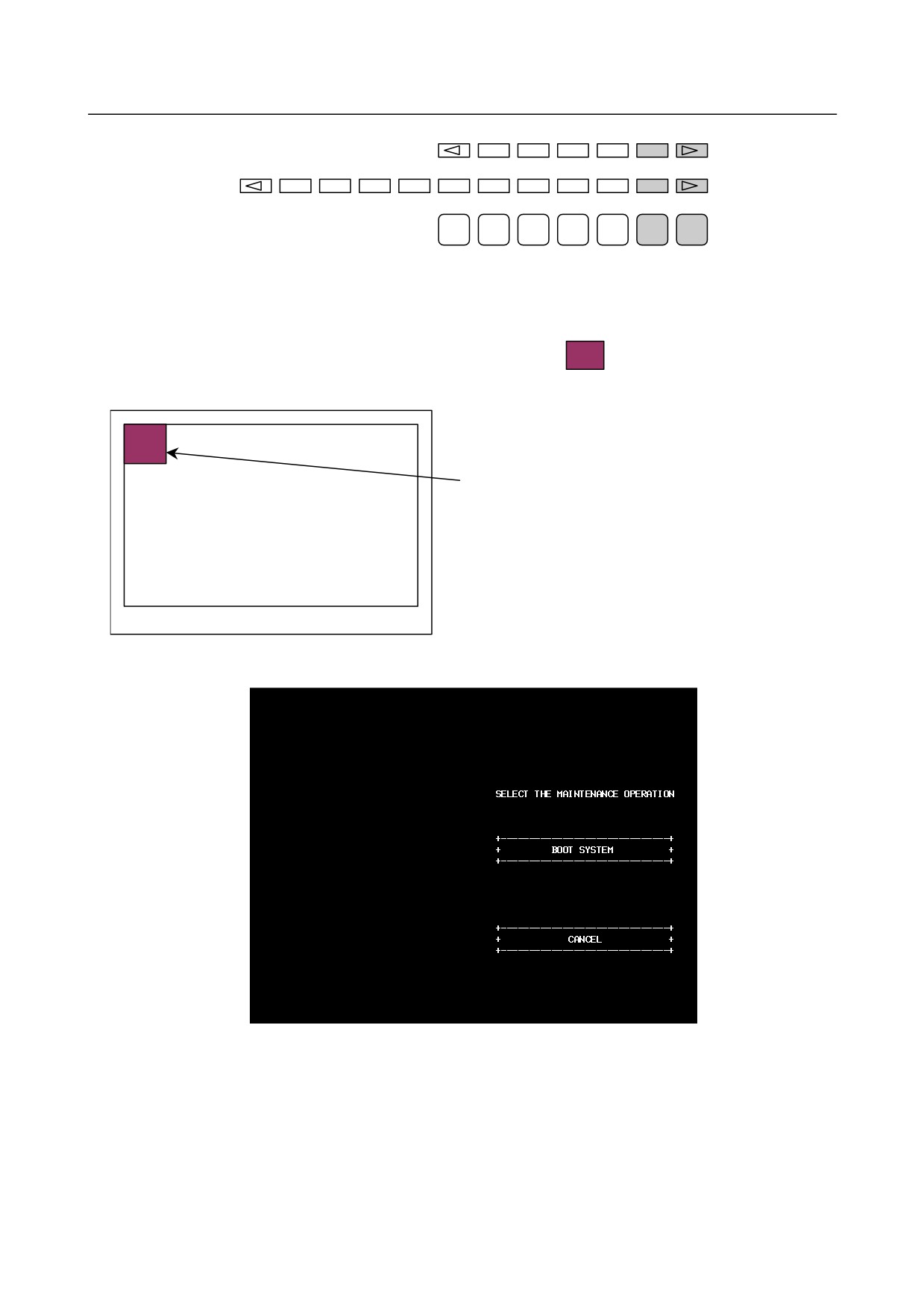
(1) In system maintenance, for example, to replace a file in ROM operation
-
When soft keys or MDI keys are present
Turn on the power while pressing the rightmost soft key and the soft key to the right at the same time.
Numerical keys 6 and 7 on the MDI keyboard can also be used.
- 509 -
C.BOOT SYSTEM
APPENDIX
B-64305EN/03
1
2
3
4
5
6
7
After an FROM ID and other items are displayed on the CNC screen, releasing the key brings you to
the SYSTEM MONITOR screen.
-
When soft keys or MDI keys are not present (touch panel)
In the CNC power-off state, turn on the power while pressing
at the upper-left corner of the
touch panel screen.
Turn on the power while
Touch panel screen
pressing this position.
The maintenance operation screen below appears after a while.
When the rectangle enclosing "BOOT SYSTEM" is pressed on the maintenance operation screen, the
SYSTEM MONITOR screen appears.
When the rectangle enclosing "CANCEL" is pressed on the maintenance operation screen, the CNC
system starts up.
- 510 -
B-64305EN/03
APPENDIX
C.BOOT SYSTEM
NOTE
1 If the area to be pressed on a touch panel is large, the response is reduced.
Please use a special stylus or the like.
2 This function is enabled only when the 10.4-inch LCD with a touch panel is used
as the display unit.
(2) When the flash memory does not contain a file required to start the CNC
Immediately after the CNC is turned on, the boot system starts transferring files from Flash ROM to
DRAM. If, for some reason, a file required to start the CNC (NC BASIC) is not in Flash ROM or has
been destroyed, the boot system is automatically started.
C.1.3 System Files and User Files
The boot system organizes files in Flash ROM into two main groups : system files and user files. These
two file types have the following characteristics :
System files
Control software for the CNC or servo provided by FANUC
User files
PMC sequence program (ladder), P-CODE macro program, and other user-created files
Naming convention for user files
Each of the files in flash ROM has a specific name based on its type. These file names are used by the
following items described later.
• SYSTEM DATA CHECK
• SYSTEM DATA DELETE
• SYSTEM DATA SAVE
The correspondence between the file names and their types is shown below.
File name
Type
PMC□
Ladder
PMCS
Ladder (for dual check safety)
M□PMCMSG
PMC message multi-language data
CEX □.□M
C language executor user application
CEX□○○○○
C language executor user data
PC0Δ○○○○ or
Macro executor user application
PC0Δ○.○○
□: One numeric
Δ: Numeric 1 to 6
○: One numeric or one alphanumeric
- 511 -
C.BOOT SYSTEM
APPENDIX
B-64305EN/03
C.2 SCREEN CONFIGURATION AND OPERATING
PROCEDURE
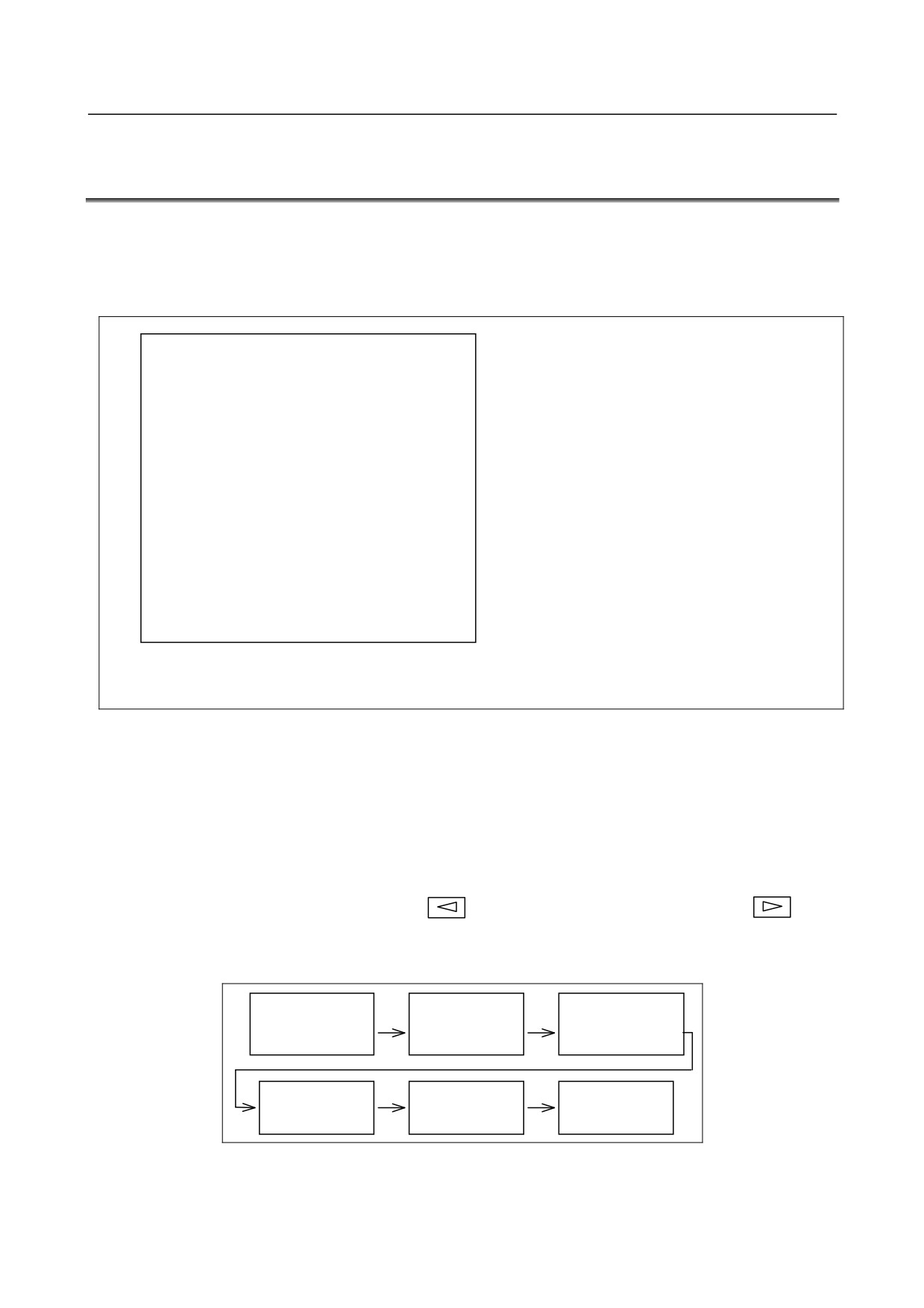
When the boot system is first started, the MAIN MENU screen is displayed. This screen is described
below :
MAIN MENU screen
(1)
SYSTEM MONITOR MAIN MENU
60W3 - 01
(1) Screen title. The series and edition of
the BOOT SYSTEM are displayed at
(2)
1.END
the right end.
(3)
2.USER DATA LOADING
(2) Function for terminating the boot
(4)
3.SYSTEM DATA LOADING
system and starting the CNC.
(5)
4.SYSTEM DATA CHECK
(3) Function for writing data to Flash
(6)
5.SYSTEM DATA DELETE
ROM.
(7)
6.SYSTEM DATA SAVE
(4) Function for writing data to Flash
(8)
7.SRAM DATA BACKUP
ROM.
(9)
8.MEMORY CARD FORMAT
(5) Function for checking the edition of a
file in ROM.
(6) Function for deleting a file from Flash
*** MESSAGE ***
ROM or Memory card.
(10)
SELECT MENU AND HIT SELECT KEY.
(7) Function for making a backup copy of
the data stored on the Memory card.
[SELECT][ YES
][ NO
][ UP
][ DOWN ]
(8) Function for backing up and restoring
the SRAM area
(9) Function for formatting a Memory card.
(10) Simple operating instructions and error
messages are displayed.
Operating procedure
-
For other than the touch panel
Press the [UP] or [DOWN] soft key to select the desired function. After positioning the cursor to the
desired function, press the [SELECT] soft key. Before executing a function, for a confirmation, it maybe
need to press the [YES] or [NO] soft key.
-
For the touch panel
This procedure directly presses [SELECT], [YES], [NO], [UP], and [DOWN] on the screen. For the
touch panel, [PREV] equivalent to soft key
and [NEXT] equivalent to soft key
are
displayed, so press these keys for operation.
Basic operation
Position the cursor.
Select a function
Check the selection
[ UP ]
[SELECT]
[ YES ]
[ DOWN ]
[ NO ]
Execute the
Return to original
function
Select END
state
- 512 -
B-64305EN/03
APPENDIX
C.BOOT SYSTEM
C.2.1 USER DATA LOADING/SYSTEM DATA LOADING Screen
Description
This screen is used to read a system or user file from a Memory card into Flash ROM.
The USER DATA LOADING screen is used to load ROM data from a Memory card to flash memory.
The SYSTEM DATA LOADING screen is used to check the contents of the ROM card installed in a
Memory card and then load ROM data from the Memory card to flash memory.
Screen configuration
(1)
SYSTEM DATA LOADING
(1) Screen title.
(2)
MEMORY CARD DIRECTORY
(FREE[KB]:
5123)
(2) The size of the free space of the
(3)
1 D4F1_B1.MEM 1048704 2003-01-01 12:00
Memory card is displayed.
2 D4F1_B2.MEM 1048704 2003-01-01 12:00
(3) A list of files in the Memory card is
(4)
3 END
displayed.
*** MESSAGE ***
(4) Returning to the MAIN MENU.
(5)
SELECT MENU AND HIT SELECT KEY.
[SELECT][ YES
][ NO
][ UP
][ DOWN ]
(5) Message
Operating procedure
(1) Position the cursor to the file to be read from the Memory card and written to Flash ROM. Then,
press the [SELECT] soft key.
-
A single page can list up to ten file names.
-
If the Memory card contains ten or more files, the remaining files are displayed on another
page.
To display the next page, press the
soft key.
To display the previous page, press the
soft key. The END option is displayed on the
last page.
(2) When you select a file from the USER DATA LOADING screen, you are prompted for
confirmation.
USER DATA LOADING
MEMORY CARD DIRECTORY
(FREE[KB]:
5123)
1 D4F1_B1.MEM 1048704 2003-01-01 12:00
2 D4F1_B2.MEM 1048704 2003-01-01 12:00
3 END
*** MESSAGE ***
LOADING OK ? HIT YES OR NO.
[SELECT][ YES
][ NO
][ UP
][ DOWN ]
- 513 -
C.BOOT SYSTEM
APPENDIX
B-64305EN/03
(3)
When you select a file from the SYSTEM DATA LOADING screen, a ROM data confirmation
screen is displayed for confirmation.
SYSTEM DATA CHECK & DATA LOADING
D4F1_B1.MEM
1 D4F1 001A
2 D4F1 021A
3 D4F1 041A
4 D4F1 061A
5 D4F1 081A
6 D4F1 0A1A
7 D4F1 0C1A
8 D4F1 0E1A
*** MESSAGE ***
LOADING OK ? HIT YES OR NO.
[SELECT][ YES
][ NO
][ UP
][ DOWN ]
(4)
To start loading, press the [YES] soft key. To cancel, press the [NO] key.
*** MESSAGE ***
LOADING FROM MEMORY CARD xxxxxx/xxxxxx
[SELECT][ YES
][ NO
][ UP
][ DOWN ]
(5)
When loading terminates normally, the system displays the following message. Press the [SELECT]
soft key. If an error occurs, see C.3
*** MESSAGE ***
LOADING COMPLETE.
HIT SELECT KEY.
[SELECT][ YES
][ NO
][ UP
][ DOWN ]
NOTE
1 The option parameters of the CNC are saved in the option information file
(OPRM INF). If this file is modified, the option parameters need to be certified
because the settings of the option parameter are assumed to be changed.
2 Since the option information file (OPRM INF) may be necessary when the
printed circuit board is replaced, it is recommended that this file be backed up in
advance as in SRAM data.
- 514 -

B-64305EN/03
APPENDIX
C.BOOT SYSTEM
C.2.2 SYSTEM DATA CHECK Screen
Description
This screen is used to list files in Flash ROM or Memory card, together with the corresponding numbers
of management units in each file and the series and edition of the software.
Screen configuration
(1)
SYSTEM DATA CHECK
(1) Screen title.
(2)
1.FROM SYSTEM
(2) Select the FROM SYSTEM screen.
(3)
2.MEMORY CARD SYSTEM
(3) Select the MEMORY CARD SYSTEM
(4)
3.END
screen.
(4) Returning to the MAIN MENU.
*** MESSAGE ***
(5)
SELECT MENU AND HIT SELECT KEY.
(5) Message
[SELECT][ YES
][ NO
][ UP
][ DOWN ]
Screen configuration (FROM SYSTEM screen)
(1)
SYSTEM DATA CHECK
(1) Screen title.
FROM DIRECTORY
(2)
1 NC BAS-1(0008)
(2) Names of files in Flash ROM The
2 NC BAS-2(0008)
number of management units
3 NC BAS-3(0008)
constituting each file appears in
4 NC BAS-4(0008)
parentheses to the right of the filename.
5 DGD0SRVO(0003)
6 PS0B
(0006)
(3)
7 END
(3) Returning to the MAIN MENU.
*** MESSAGE ***
(4)
SELECT FILE AND HIT SELECT KEY.
(4) Message
[SELECT][ YES
][ NO
][ UP
][ DOWN ]
- 515 -

C.BOOT SYSTEM
APPENDIX
B-64305EN/03
Screen configuration (MEMORY CARD SYSTEM screen)
(1)
SYSTEM DATA CHECK
(1) Screen title.
(2)
MEMORY CARD DIRECTORY
(FREE[KB]:
5123)
(2) The size of the free space of the
(3)
1 D4F1_B1.MEM 1048704 2003-01-01 12:00
Memory card is displayed.
2 D4F1_B2.MEM 1048704 2003-01-01 12:00
(3) A list of files in the Memory card is
(4)
3 END
displayed.
(4) Returning to the MAIN MENU.
*** MESSAGE ***
(5)
SELECT FILE AND HIT SELECT KEY.
(5) Message
[SELECT][ YES
][ NO
][ UP
][ DOWN ]
Operating procedure
(1) Select either the FROM SYSTEM or MEMORY CARD SYSTEM screen.
(2) Select the file that you want to confirm (for example, "NC BAS-1 (0008)").
(3) For the selected file, the management unit numbers are listed, together with the series and editions of
the management units. After checking the listed data, select the [SELECT] soft key to return to the
file selection screen.
(1)
SYSTEM DATA CHECK
(1) Screen title.
NC BAS-1(0008)
(2)
1 D4F1 001A 0000
(2) The following items are displayed for
2 D4F1 021A 0001
each management unit:
3 D4F1 041A 0002
- Series
4 D4F1 061A 0003
- ROM number and edition
5 D4F1 081A 0004
- Internal management-unit number
6 D4F1 0A1A 0005
If a check result cannot be displayed, a
7 D4F1 0C1A 0006
"@" is displayed.
8 D4F1 0E1A 0007
*** MESSAGE ***
HIT SELECT KEY.
[SELECT][ YES
][ NO
][ UP
][ DOWN ]
Others (Parity information for the system file and user file)
The NC BAS-1, DGD0SRVO, and other system files in Flash ROM contain parity information in each
management unit. If the file name field or parity field on the check screen contains a non-ASC II
character or an "@", the Flash ROM may have been destroyed or a damaged file may have been read.
Re-read the data from the Memory card.
The PMC1, and other user files do not contain parity information in each management unit. A non-ASCII
character or an "@" may appear in the series/edition information. In this case, it does not indicate that the
file has been damaged.
- 516 -

B-64305EN/03
APPENDIX
C.BOOT SYSTEM
C.2.3 SYSTEM DATA DELETE Screen
Description
This screen is used to delete a user file from Flash ROM or Memory card.
Screen configuration
(1)
SYSTEM DATA DELETE
(1) Screen title.
(2)
1.FROM SYSTEM
(2) Select the FROM SYSTEM screen.
(3)
2.MEMORY CARD SYSTEM
(3) Select the MEMORY CARD SYSTEM
(4)
3.END
screen.
(4) Returning to the MAIN MENU.
*** MESSAGE ***
(5)
SELECT MENU AND HIT SELECT KEY.
(5) Message
[SELECT][ YES
][ NO
][ UP
][ DOWN ]
Screen configuration (FROM SYSTEM screen)
(1)
SYSTEM DATA DELETE
(1) Screen title.
FROM DIRECTORY
(2)
1 NC BAS-1(0008)
(2) Names of files in Flash ROM
2 NC BAS-2(0008)
The number of management units
3 NC BAS-3(0008)
constituting each file appears in
4 NC BAS-4(0008)
parentheses to the right of the filename.
5 DGD0SRVO(0003)
6 PS0B
(0006)
7 PMC1
(0001)
(3)
8 END
(3) Returning to the MAIN MENU.
*** MESSAGE ***
(4)
SELECT FILE AND HIT SELECT KEY.
(4) Message
[SELECT][ YES
][ NO
][ UP
][ DOWN ]
Screen configuration (MEMORY CARD SYSTEM screen)
SYSTEM DATA DELETE
(1)
(1) Screen title.
MEMORY CARD DIRECTORY
(FREE[KB]:
5123)
(2)
(2) The size of the free space of the
1 D4F1_B1.MEM 1048704 2003-01-01 12:00
(3)
Memory card is displayed.
2 D4F1_B2.MEM 1048704 2003-01-01 12:00
(3) A list of files in the Memory card is
3 END
(4)
displayed.
(4) Returning to the MAIN MENU.
*** MESSAGE ***
SELECT FILE AND HIT SELECT KEY.
(5)
(5) Message
[SELECT][ YES
][ NO
][ UP
][ DOWN ]
- 517 -
C.BOOT SYSTEM
APPENDIX
B-64305EN/03
Operating procedure
(1) Select either the FROM SYSTEM or MEMORY CARD SYSTEM screen.
(2) Select the file you want to delete.
(3) The following message is displayed for confirmation.
*** MESSAGE ***
DELETE OK ? HIT YES OR NO.
[SELECT][ YES
][ NO
][ UP
][ DOWN ]
(4) To start deleting, press the [YES] soft key. To cancel, press the [NO] key.
*** MESSAGE ***
EXECUTING
ADDRESS xxxx:
[SELECT][ YES
][ NO
][ UP
][ DOWN ]
(5) When deleting terminates normally, the system displays the following message. Press the [SELECT]
soft key. If an error occurs, see C.3
*** MESSAGE ***
DELETE COMPLETE. HIT SELECT KEY.
[SELECT][ YES
][ NO
][ UP
][ DOWN ]
Others (System files and user files on SYSTEM DATA DELETE screen)
The system files are protected from accidental deletion. User files, however, are not protected. Protected
system files can be overwritten from the USER DATA LOADING / SYSTEM DATA LOADING screen.
C.2.4 SYSTEM DATA SAVE Screen
Description
This screen is used to write a user file in Flash ROM to a Memory card. Only user files can be saved from
Flash ROM to a Memory card. System files cannot be saved.
Screen configuration
(1)
SYSTEM DATA SAVE
(1) Screen title.
FROM DIRECTORY
(2)
1 NC BAS-1(0008)
(2) Names of files in Flash ROM
2 NC BAS-2(0008)
The number of management units
3 NC BAS-3(0008)
constituting each file appears in
4 NC BAS-4(0008)
parentheses to the right of the filename.
5 DGD0SRVO(0003)
6 PS0B
(0006)
7 PMC1
(0001)
(3)
8 END
(3) Returning to the MAIN MENU.
*** MESSAGE ***
(4)
SELECT FILE AND HIT SELECT KEY.
(4) Message
[SELECT][ YES
][ NO
][ UP
][ DOWN ]
- 518 -
B-64305EN/03
APPENDIX
C.BOOT SYSTEM
Operating procedure
(1) Select the file you want to save.
(2) The system displays the following confirmation message :
*** MESSAGE ***
SYSTEM DATA SAVE OK ? HIT YES OR NO.
[SELECT][ YES
][ NO
][ UP
][ DOWN ]
(3) To start saving, press the [YES] key. To cancel, press [NO].
*** MESSAGE ***
STORE TO MEMORY CARD
[SELECT][ YES
][ NO
][ UP
][ DOWN ]
(4) When saving terminates normally, the system displays the following message. Press the [SELECT]
key. The names of files written to the Memory card are listed. Check the file names by, for example,
making a note of the list.
*** MESSAGE ***
FILE SAVE COMPLETE. HIT SELECT KEY.
SAVE FILE NAME : PMC1.000
[SELECT][ YES
][ NO
][ UP
][ DOWN ]
Saving ATA PROG
A file whose file name is ATA PROG contains an NC program. Even if you want to save this file, you
cannot save it on this SYSTEM DATA SAVE screen, because it is saved together with SRAM data on the
SRAM DATA UTILITY screen.
Others (System files and user files on SYSTEM DATA SAVE screen)
The SYSTEM DATA SAVE function provides a safeguard against free copying of the system files.
User files, however, are not protected.
Files saved from Flash ROM to a Memory card have the following names :
Header ID in Flash ROM
File name in Memory card
PMC1
→
PMC1.xxx
PC010.5M
→
PC0105M.xxx
PC011.0M
→
PC0110M.xxx
"xxx" is replaced by one of 32 numbers "000", "001", …, and "031".
For example, if you attempt to save the file "PMC1 " from Flash ROM to a Memory card, it will be
saved with a name of "PMC1.000" if no file with a name of "PMC1.000" is found on the Memory card. If,
however, that file is saved to a Memory card that already contains a file named PMC1.000, the saved file
is named PMC1.001. As files are added, the extension is incremented up to a maximum of PMC1.031.
Any no-longer used numbers in the sequence of the extension numbers are used in as sending order. If
two or more files having identical names but different extension numbers are normally saved to the
Memory card, check the file names displayed subsequently.
- 519 -

C.BOOT SYSTEM
APPENDIX
B-64305EN/03
C.2.5 SRAM DATA UTILITY Screen
Description
This screen is used to collectively save and restore parameters, tool compensation memories, and other
data, retained after the CNC power in SRAM is turned off, to and from a Memory card.
Automatic data backup (optional function) is available to restore data backed up in the FROM in the
CNC.
Screen configuration
(1)
SRAM DATA UTILITY
(1) Screen title.
(2)
1.SRAM BACKUP
( CNC -> MEMORY CARD )
(2) Menu
2.SRAM RESTORE ( MEMORY CARD -> CNC )
3.AUTO BKUP RESTORE ( FROM -> CNC )
(3)
4.END
(3) Returning to the MAIN MENU.
(4)
SRAM + ATA PROG FILE : (4MB)
(4) The SRAM file size is displayed.
(Displayed after a processing option is
selected.)
(5)
SRAM_BAK.001
(5) The name of the file currently being
saved or loaded is displayed. (Displayed
*** MESSAGE ***
after a processing option is selected.)
SET MEMORY CARD NO.001
ARE YOU SURE ? HIT YES OR NO.
[SELECT][ YES
][ NO
][ UP
][ DOWN ]
*** MESSAGE ***
SELECT MENU AND HIT SELECT KEY.
(6)
(6) Message
[SELECT][ YES
][ NO
][ UP
][ DOWN ]
Operating procedure (Backing up data)
(1) Select "1.SRAM BACKUP" The following confirmation message is displayed. To start backup,
press the [YES] soft key.
(2) If the data cannot be saved entirely onto a single Memory card, a message such as that shown below
is displayed. With the power still on, insert the second Memory card and press the [YES] key. Press
the [NO] key to cancel saving.
*** MESSAGE ***
SET MEMORY CARD NO.002
ARE YOU SURE ? HIT YES OR NO.
[SELECT][ YES
][ NO
][ UP
][ DOWN ]
(3) In this way, you can divide SRAM data onto a maximum of 999 Memory card for backup.
- 520 -
B-64305EN/03
APPENDIX
C.BOOT SYSTEM
(4) Upon the termination of backup, the system displays the following message. Press the [SELECT]
soft key.
*** MESSAGE ***
SRAM BACKUP COMPLETE. HIT SELECT KEY.
[SELECT][ YES
][ NO
][ UP
][ DOWN ]
Operating procedure (Restoring the data)
(1)
Select "2.RESTORE SRAM" The following confirmation message is displayed. To start restoration,
press the [YES] soft key.
(2)
A message such as that shown below is displayed. Insert the first Memory card containing
SRAMBACK.001 and press the [YES] key. Press the [NO] key to cancel restoration.
*** MESSAGE ***
SET MEMORY CARD INCLUDING SRAM_BAK.001
ARE YOU SURE ? HIT YES OR NO.
[SELECT][ YES
][ NO
][ UP
][ DOWN ]
(3)
If another Memory card is required, a message such as that shown below is displayed. With the
power still on, insert the second Memory card and press the [YES] key. Press the [NO] key to cancel
restoration.
*** MESSAGE ***
SET MEMORY CARD INCLUDING SRAM_BAK.002
ARE YOU SURE ? HIT YES OR NO.
[SELECT][ YES
][ NO
][ UP
][ DOWN ]
(4)
Replace the second card with another, if required. Repeat this step until backing up all data.
(5)
Upon the termination of restoration, the system displays the following message. Press the [SELECT]
soft key.
*** MESSAGE ***
SRAM RESTORE COMPLETE. HIT SELECT KEY.
[SELECT][ YES
][ NO
][ UP
][ DOWN ]
CAUTION
1 Backup files will be created with a file name of SRAMBAK.xxx, where xxx is
replaced with a number between 001 and 999 sequentially.
On the first Memory card, a backup file is created with a name of SRAMBAK.001.
If all data is not contained on the single card, a backup file containing the excess
data is created with a name of SRAMBAK.002 on the second Memory card.
In this way, you can divide data onto a maximum of 999 Memory card for saving.
2 Check that the Memory card used for backup does not contain a file with a name
of SRAMBAK.xxx before performing a BACKUP operation. You can check a list
of file names on a Memory card by using the SYSTEM DATA LOADING function.
3 The Memory card used for backup needs to be formatted in FAT16.
- 521 -

C.BOOT SYSTEM
APPENDIX
B-64305EN/03
Operating procedure (Restoring backup data using automatic data backup
(option))
(1) Select "3.AUTO BKUP RESTORE." The following menu is displayed.
(When the FROM contains no backup data, “1. END” is displayed.)
AUTO BACKUP DATA RESTORE
1. BACKUP DATA1 yyyy/mm/dd **:**:**
2. BACKUP DATA2 yyyy/mm/dd **:**:**
3. BACKUP DATA3 yyyy/mm/dd **:**:**
4. END
(2) Select data from the above menu and execute restoration.
Selecting END displays the SRAM DATA UTILITY screen again.
(3) Upon the termination of restoration, the system displays the following message.
Press the [SELECT] key to terminate operation.
(The MAIN MENU screen of the boot system is
displayed again.)
*** MESSAGE ***
RESTORE COMPLETE. HIT SELECT KEY.
[SELECT][ YES
][ NO
][ UP
][ DOWN ]
C.2.6 MEMORY CARD FORMAT Screen
Description
This function is used to format a Memory card. Memory cards must be formatted before they can be used
for the first time or before they can be re-used after their data has been destroyed or lost because of, for
example, battery failure.
Operating procedure
(1) From the MAIN MENU screen, select "8.MEMORY CARD FORMAT."
(2) The system displays the following confirmation message. Press the [YES] key.
*** MESSAGE ***
MEMORY CARD FORMAT OK ? HIT YES OR NO.
[SELECT][ YES
][ NO
][ UP
][ DOWN ]
(3) The system displays the following message asking whether to delete all data on the Memory card.
To format the Memory card, press the [YES] key.
*** MESSAGE ***
MEMORY CARD FORMAT OK ? HIT YES OR NO.
ALL DATA IN THE MEMORY CARD IS LOST.
[SELECT][ YES
][ NO
][ UP
][ DOWN ]
- 522 -
B-64305EN/03
APPENDIX
C.BOOT SYSTEM
(4) The system displays the following message during formatting :
*** MESSAGE ***
FORMATTING MEMORY CARD.
[SELECT][ YES
][ NO
][ UP
][ DOWN ]
(5) When a card has been formatted normally, the system display the following message. Press the
[SELECT] soft key.
*** MESSAGE ***
FORMAT COMPLETE. HIT SELECT KEY.
[SELECT][ YES
][ NO
][ UP
][ DOWN ]
C.2.7 LOAD BASIC SYSTEM
Description
The function is used to terminate the boot system and activate the CNC.
Operating procedure
From the MAIN MENU screen, select "1. END." The system displays the "ARE YOU SURE? HIT YES
OR NO" message. To terminate the boot system and activate the CNC, press the [YES] soft key. Press the
[NO] soft key, and you will be brought back to the MAIN MENU.
*** MESSAGE ***
ARE YOU SURE ? HIT YES OR NO.
[SELECT][ YES
][ NO
][ UP
][ DOWN ]
C.3 ERROR MESSAGES AND REQUIRED ACTIONS
The following table lists and explains error messages in alphabetical order.
Message
Description and required action
D
DEVICE ERROR (xxxx)
An attempt to write data to Flash ROM was unsuccessful.
Turn the power off and back on again. If the second
attempt also fails, the Flash ROM may have been
damaged or destroyed. Replace the Flash ROM module.
F
FILE CLOSE ERROR.
Access to a Memory card failed. The Memory card’s
HIT SELECT KEY.
battery may have gone dead, the Memory card may have
been damaged electrically, or the Memory card may not be
inserted in the slot securely.
FILE DELETE ERROR.
Access to a Memory card failed. The Memory card’s
HIT SELECT KEY.
battery may have gone dead, the Memory card may have
been damaged electrically, or the Memory card may not be
inserted in the slot securely.
FILE OPEN ERROR.
Access to a Memory card failed. Confirm that the Memory
HIT SELECT KEY.
card is FAT16-formatted.
(If the Memory card is formatted
in FAT32, it cannot be recognized.)
- 523 -
C.BOOT SYSTEM
APPENDIX
B-64305EN/03
Message
Description and required action
F
FILE READ ERROR.
Access to a Memory card failed. The Memory card’s
HIT SELECT KEY.
battery may have gone dead, the Memory card may have
been damaged electrically, or the Memory card may not be
inserted in the slot securely.
FILE SAVE ERROR.
Access to a Memory card failed. The Memory card’s
HIT SELECT KEY.
battery may have gone dead, the Memory card may have
been damaged electrically, or the Memory card may not be
inserted in the slot securely.
FLASH MEMORY NO SPACE.
There is insufficient free Flash ROM to store the selected
HIT SELECT KEY.
file. Delete any unnecessary files from Flash ROM.
I
ILLEGAL FORMAT FILE.
The selected file cannot be read into Flash ROM. The
HIT SELECT KEY.
selected file or the header information for Flash ROM may
have been damaged or destroyed.
ILLEGAL SRAM MODULE.
The SRAM module ID is illegal. Check the drawing No. of
HIT SELECT KEY.
the SRAM module.
M
MAX EXTENSION OVER. HIT SELECT KEY.
The extension number added to a file name exceeds 031.
Either replace the Memory card or delete any unnecessary
backup files.
MEMORY CARD BATTERY ALARM.
The Memory card's battery is exhausted. Replace the
HIT SELECT KEY.
battery.
MEMORY CARD DISMOUNT ERROR.
Access to a Memory card failed. The Memory card’s
HIT SELECT KEY.
battery may have gone dead, the Memory card may have
been damaged electrically, or the Memory card may not be
inserted in the slot securely.
MEMORY CARD FORMAT ERROR
Access to a Memory card failed. The Memory card’s
battery may have gone dead, the Memory card may have
been damaged electrically, or the Memory card may not be
inserted in the slot securely.
MEMORY CARD FULL.
The Memory card is full. Delete any unnecessary files from
HIT SELECT KEY.
the Memory card. Alternatively, replace the Memory card
with another card having sufficient free space.
MEMORY CARD MOUNT ERROR.
Access to a Memory card failed. Check that the Memory
HIT SELECT KEY.
card has been FAT16-formatted. (When the Memory card
has been FAT32-formatted, it is not recognized.)
MEMORY CARD NOT EXIST.
The Memory card is not inserted into its slot. Check that
HIT SELECT KEY.
the Memory card is pushed fully home.
MEMORY CARD PROTECTED. HIT SELECT
Although writing to the Memory card was selected, the
KEY.
write inhibit switch is set. Disable the write inhibit switch.
MEMORY CARD RESET ERROR.
Access to a Memory card failed. The Memory card’s
HIT SELECT KEY.
battery may have gone dead, the Memory card may have
been damaged electrically, or the Memory card may not be
inserted in the slot securely.
R
ROM PARITY ERROR:NC BASIC. HIT
NC BASIC data is not correct. Use SYSTEM DATA
SELECT.
CHECK to check that CNC system software is installed.
S
SRAM TEST ERROR (ECC)
An error was detected in the SRAM module. You can start
up the system because data has been automatically
restored. Replace the SRAM module, however, just in case
that the data may be disarranged in the future.
- 524 -
B-64305EN/03
APPENDIX
D.MEMORY CARD SLOT
D MEMORY CARD SLOT
Appendix D, "MEMORY CARD SLOT", consists of the following sections:
D.1 OVERVIEW
525
D.2 TYPES OF AVAILABLE MEMORY CARDS
525
D.3 HARDWARE CONFIGURATION
527
D.1 OVERVIEW
Whether a memory card slot is provided or not depends on the hardware configuration. See the following
table:
Hardware configuration
Card slot on LCD unit
Card slot on control unit
Type 1
Provided
No card slot
Provided
Type 3
(when PANEL i is used)
Provided
(See NOTE given below.)
(Supplementary)
-
Types 1 and 3 indicate hardware configuration. See Section D.3.
NOTE
When the hardware configuration is type 3, software write operation and other
operations are implemented by open CNC functions.
D.2 TYPES OF AVAILABLE MEMORY CARDS
Flash ATA card (Data I/O)
Compact flash card (Data I/O)
NOTE
Use memory cards that are recommended by or purchased from FANUC.
Use of the compact flash card adapter in the card slot
When a compact flash card is inserted into a compact flash card adapter (A02B-0303-K150) (referred to
below as the CF adapter) purchased from FANUC, and then the CF adapter is inserted into the card slot
on the display unit side, the compact flash card lock function is available, the memory card interface
cover can be closed with the CF adapter inserted.
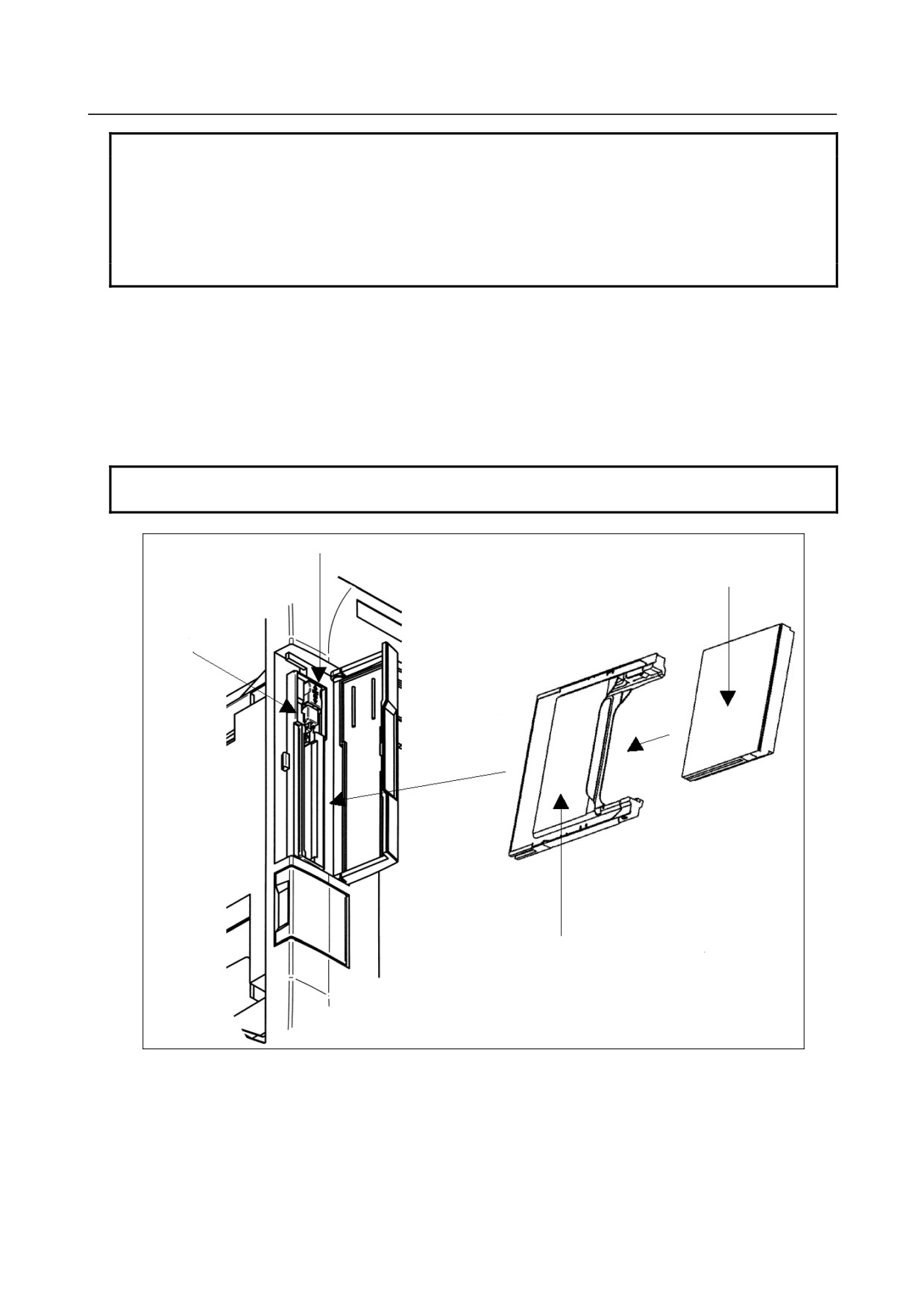
1.
Insertion
-
Set a compact flash card in the CF adapter (A02B-0303-K150).
-
Check that lock lever A is lifted, then insert the CF adapter into the memory card interface.
-
Lower lock lever A.
-
Close the memory card interface cover.
- 525 -
D.MEMORY CARD SLOT
APPENDIX
B-64305EN/03
NOTE
1 This adapter is available only with the LCD-mounted type. It is unavailable with
the stand-alone type.
2 For continuous operation with a CF adapter inserted, be sure to lower lock lever
A and close the memory card interface cover.
3 The lock function is enabled only when a CF adapter (A02B-0303-K150) is used.
4 Insert a CF adapter so that the plane bearing the label faces the screen.
2.
Extraction
-
Open the cover of the memory card interface.
-
Push up lock lever A.
-
Push eject button B once. The button protrudes.
-
Push eject button B again. The CF adapter is ejected.
-
Hold the CF adapter with fingers and pull it out.
-
Close the memory card interface cover.
NOTE
When the lock lever is lowered (locked), the eject button cannot be pushed.
Lock lever A
Compact flash card
Eject button B
Compact flash card adapter
- 526 -