FANUC Series 0i-MODEL D, FANUC Series 0i Mate-MODEL D. MAINTENANCE MANUAL - page 1
B-64305EN/03
SAFETY PRECAUTIONS
SAFETY PRECAUTIONS
This section describes the safety precautions related to the use of CNC units. It is essential that these
precautions be observed by users to ensure the safe operation of machines equipped with a CNC unit (all
descriptions in this section assume this configuration).
CNC maintenance involves various dangers. CNC maintenance must be undertaken only by a qualified
technician.
Users must also observe the safety precautions related to the machine, as described in the relevant manual
supplied by the machine tool builder.
Before checking the operation of the machine, take time to become familiar with the manuals provided by
the machine tool builder and FANUC.
Contents
DEFINITION OF WARNING, CAUTION, AND NOTE
s-1
WARNINGS RELATED TO CHECK OPERATION
s-1
WARNINGS RELATED TO REPLACEMENT
s-2
WARNINGS RELATED TO PARAMETERS
s-3
WARNINGS, CAUTIONS, AND NOTES RELATED TO DAILY MAINTENANCE
s-3
DEFINITION OF WARNING, CAUTION, AND NOTE
This manual includes safety precautions for protecting the maintenance personnel (herein referred to as
the user) and preventing damage to the machine. Precautions are classified into Warnings and Cautions
according to their bearing on safety. Also, supplementary information is described as a Note. Read the
Warning, Caution, and Note thoroughly before attempting to use the machine.
WARNING
Applied when there is a danger of the user being injured or when there is a
danger of both the user being injured and the equipment being damaged if the
approved procedure is not observed.
CAUTION
Applied when there is a danger of the equipment being damaged, if the
approved procedure is not observed.
NOTE
The Note is used to indicate supplementary information other than Warning and
Caution.
* Read this manual carefully, and store it in a safe place.
WARNINGS RELATED TO CHECK OPERATION
WARNING
1.
When checking the operation of the machine with the cover removed
(1) The user's clothing could become caught in the spindle or other components, thus presenting a
danger of injury. When checking the operation, stand away from the machine to ensure that
your clothing does not become tangled in the spindle or other components.
s-1
SAFETY PRECAUTIONS
B-64305EN/03
(2) When checking the operation, perform idle operation without workpiece. When a workpiece is
mounted in the machine, a malfunction could cause the workpiece to be dropped or destroy the
tool tip, possibly scattering fragments throughout the area. This presents a serious danger of
injury. Therefore, stand in a safe location when checking the operation.
2.
When checking the machine operation with the power magnetics cabinet door opened
(1) The power magnetics cabinet has a high-voltage section (carrying a
mark). Never touch
the high-voltage section. The high-voltage section presents a severe risk of electric shock.
Before starting any check of the operation, confirm that the cover is mounted on the
high-voltage section. When the high-voltage section itself must be checked, note that touching
a terminal presents a severe danger of electric shock.
(2) Within the power magnetics cabinet, internal units present potentially injurious corners and
projections. Be careful when working inside the power magnetics cabinet.
3.
Never attempt to machine a workpiece without first checking the operation of the machine. Before
starting a production run, ensure that the machine is operating correctly by performing a trial run
using, for example, the single block, feedrate override, or machine lock function or by operating the
machine with neither a tool nor workpiece mounted. Failure to confirm the correct operation of the
machine may result in the machine behaving unexpectedly, possibly causing damage to the
workpiece and/or machine itself, or injury to the user.
4.
Before operating the machine, thoroughly check the entered data.
Operating the machine with incorrectly specified data may result in the machine behaving
unexpectedly, possibly causing damage to the workpiece and/or machine itself, or injury to the user.
5.
Ensure that the specified feedrate is appropriate for the intended operation. Generally, for each
machine, there is a maximum allowable feedrate. The appropriate feedrate varies with the intended
operation. Refer to the manual provided with the machine to determine the maximum allowable
feedrate. If a machine is run at other than the correct speed, it may behave unexpectedly, possibly
causing damage to the workpiece and/or machine itself, or injury to the user.
6.
When using a tool compensation function, thoroughly check the direction and amount of
compensation. Operating the machine with incorrectly specified data may result in the machine
behaving unexpectedly, possibly causing damage to the workpiece and/or machine itself, or injury to
the user.
WARNINGS RELATED TO REPLACEMENT
WARNING
1.
Always turn off the power to the CNC and the main power to the power magnetics cabinet. If only
the power to the CNC is turned off, power may continue to be supplied to the serve section. In such
a case, replacing a unit may damage the unit, while also presenting a danger of electric shock.
2.
When it touches the printed-circuit board or the unit, and the cable is connected, consider the
appropriate precaution as installs the list bands to prevent damage by static electricity.
The electric circuit might be damaged by static electricity from the human body.
3.
When a heavy unit is to be replaced, the task must be undertaken by two persons or more. If the
replacement is attempted by only one person, the replacement unit could slip and fall, possibly
causing injury.
4.
After the power is turned off, the servo amplifier and spindle amplifier may retain voltages for a
while, such that there is a danger of electric shock even while the amplifier is turned off. Allow at
least twenty minutes after turning off the power for these residual voltages to dissipate.
s-2
B-64305EN/03
SAFETY PRECAUTIONS
5.
When replacing a unit, ensure that the new unit has the same parameter and other settings as the old
unit. (For details, refer to the manual provided with the machine.) Otherwise, unpredictable machine
movement could damage the workpiece or the machine itself, and present a danger of injury.
WARNINGS RELATED TO PARAMETERS
WARNING
1.
When machining a workpiece for the first time after modifying a parameter, close the machine cover.
Never use the automatic operation function immediately after such a modification. Instead, confirm
normal machine operation by using functions such as the single block function, feedrate override
function, and machine lock function, or by operating the machine without mounting a tool and
workpiece. If the machine is used before confirming that it operates normally, the machine may
move unpredictably, possibly damaging the machine or workpiece, and presenting a risk of injury.
CAUTION
2.
The CNC and PMC parameters are set to their optimal values, so that those parameters usually need
not be modified. When a parameter must be modified for some reason, ensure that you fully
understand the function of that parameter before attempting to modify it. If a parameter is set
incorrectly, the machine may move unpredictably, possibly damaging the machine or workpiece, and
presenting a risk of injury.
WARNINGS, CAUTIONS, AND NOTES RELATED TO DAILY
MAINTENANCE
WARNING
1.
Memory backup battery replacement
When replacing the memory backup batteries, keep the power to the machine (CNC) turned on, and
apply an emergency stop to the machine. Because this work is performed with the power on and the
cabinet open, only those personnel who have received approved safety and maintenance training
may perform this work.
When replacing the batteries, be careful not to touch the high-voltage circuits (marked
and
fitted with an insulating cover).
Touching the uncovered high-voltage circuits presents an extremely dangerous electric shock
hazard.
NOTE
The CNC uses batteries to preserve the contents of its memory, because it must retain data such as
programs, offsets, and parameters even while external power is not applied.
If the battery voltage drops, a low battery voltage alarm is displayed on the machine operator's panel or
CRT screen.
When a low battery voltage alarm is displayed, replace the batteries within a week. Otherwise, the
contents of the CNC's memory will be lost.
To replace the battery, see the procedure described in Section 2.8 of this manual.
s-3
SAFETY PRECAUTIONS
B-64305EN/03
WARNING
2.
Absolute pulse coder battery replacement
When replacing the memory backup batteries, keep the power to the machine (CNC) turned on, and
apply an emergency stop to the machine. Because this work is performed with the power on and the
cabinet open, only those personnel who have received approved safety and maintenance training
may perform this work.
When replacing the batteries, be careful not to touch the high-voltage circuits (marked
and
fitted with an insulating cover).
Touching the uncovered high-voltage circuits presents an extremely dangerous electric shock
hazard.
NOTE
The absolute pulse coder uses batteries to preserve its absolute position.
If the battery voltage drops, a low battery voltage alarm is displayed on the machine operator's panel or
CRT screen.
When a low battery voltage alarm is displayed, replace the batteries within a week. Otherwise, the
absolute position data held by the pulse coder will be lost.
To replace the battery, see the procedure described in Section 2.10 of this manual.
WARNING
3.
Fuse replacement
Before replacing a blown fuse, however, it is necessary to locate and remove the cause of the blown
fuse.
For this reason, only those personnel who have received approved safety and maintenance training
may perform this work.
When replacing a fuse with the cabinet open, be careful not to touch the high-voltage circuits
(marked
and fitted with an insulating cover).
Touching an uncovered high-voltage circuit presents an extremely dangerous electric shock hazard.
NOTE
Liquid-crystal display
The liquid-crystal display was fabricated using a very precise processing technology. However,
please note in mind that it may have dead and always-on pixels because of its characteristics and this
is not a failure.
s-4
B-64305EN/03
PREFACE
PREFACE
The manual consists of the following chapters:
Description of this manual
1.
DISPLAY AND OPERATION
This chapter covers those items, displayed on the screen, that are related to maintenance. A list of all
supported operations is also provided at the end of this chapter.
2.
LCD-MOUNTED TYPE CNC HARDWARE
3.
STAND-ALONE TYPE CNC HARDWARE
4.
MATTERS COMMON TO BOTH LCD-MOUNTED TYPE AND STAND-ALONE TYPE
(HARDWARE)
This chapter describes the configuration of the hardware, lists the hardware units, and explains how
to replace printed-circuit boards.
5.
INPUT AND OUTPUT OF DATA
This chapter describes the input/output procedures for data, including programs, parameters, and tool
compensation data.
6.
INTERFACE BETWEEN CNC AND PMC
This chapter describes the PMC specifications, the system configuration, and the signals used by the
PMC.
7.
EMBEDDED ETHERNET FUNCTION
This chapter describes the embedded Ethernet.
8.
DIGITAL SERVO
This chapter describes the servo tuning screen and how to adjust the reference position return
position.
9.
AC SPINDLE
This chapter describes the spindle tuning screen.
10.
TROUBLESHOOTING
This chapter describes the procedures to be followed in the event of certain problems occurring, for
example, if the power cannot be turned on or if manual operation cannot be performed.
Countermeasures to be applied in the event of alarms being output are also described.
11.
MOTOR/DETECTOR/AMPLIFIER PREVENTIVE MAINTENANCE
This chapter describes the basic information about the preventive maintenance of motors, detectors,
and amplifiers.
APPENDIX
A. ALARM LIST
B. LIST OF MAINTENANCE PARTS
C. BOOT SYSTEM
D. MEMORY CARD SLOT
E. LED DISPLAY
F. MAINTENANCE OF OPEN CNC (BOOT-UP AND IPL)
G. IPL MONITOR
H. MEMORY CLEAR
This manual does not provide a parameter list. If necessary, refer to the separate PARAMETER
MANUAL.
p-1

PREFACE
B-64305EN/03
Applicable models
This manual can be used with the following models. The abbreviated names may be used.
Model name
Abbreviation
FANUC Series 0i -TD
0i -TD
Series 0i -D
0i -D
FANUC Series 0i -MD
0i -MD
FANUC Series 0i Mate -TD
0i Mate -TD
Series 0i Mate -D
0i Mate -D
FANUC Series 0i Mate -MD
0i Mate -MD
NOTE
1 For explanation purposes, these models may be classified as shown below:
- T series: 0i -TD / 0i Mate -TD
- M series: 0i -MD / 0i Mate -MD
2 Some function described in this manual may not be applied to some products.
For details, refer to the DESCRIPTIONS manual (B-64302EN).
3 The 0i -D / 0i Mate -D requires setting of parameters to enable part of basic
functions. For the parameters to be set, see Section 4.51, "PARAMETERS OF 0i
-D / 0i Mate -D BASIC FUNCTIONS" in the PARAMETER MANUAL
(B-64310EN).
p-2
B-64305EN/03
PREFACE
Related manuals of Series 0i -D, Series 0i Mate -D
The following table lists the manuals related to Series 0i -D, Series 0i Mate -D. This manual is indicated
by an asterisk(*).
Table 1 Related manuals of Series 0i-D, Series 0i Mate-D
Manual name
Specification number
DESCRIPTIONS
B-64302EN
CONNECTION MANUAL (HARDWARE)
B-64303EN
CONNECTION MANUAL (FUNCTION)
B-64303EN-1
USER’S MANUAL (Common to Lathe System/Machining Center System)
B-64304EN
USER’S MANUAL (For Lathe System)
B-64304EN-1
USER’S MANUAL (For Machining Center System)
B-64304EN-2
MAINTENANCE MANUAL
B-64305EN
*
PARAMETER MANUAL
B-64310EN
START-UP MANUAL
B-64304EN-3
Programming
Macro Executor PROGRAMMING MANUAL
B-64303EN-2
Macro Compiler PROGRAMMING MANUAL
B-64303EN-5
C Language Executor PROGRAMMING MANUAL
B-64303EN-3
PMC
PMC PROGRAMMING MANUAL
B-64393EN
Network
PROFIBUS-DP Board CONNECTION MANUAL
B-64403EN
Fast Ethernet / Fast Data Server OPERATOR’S MANUAL
B-64414EN
DeviceNet Board CONNECTION MANUAL
B-64443EN
FL-net Board CONNECTION MANUAL
B-64453EN
Dual Check Safety
Dual Check Safety CONNECTION MANUAL
B-64303EN-4
Operation guidance function
MANUAL GUIDE i (Common to Lathe System/Machining Center System)
B-63874EN
OPERATOR’S MANUAL
MANUAL GUIDE i (For Machining Center System) OPERATOR’S MANUAL
B-63874EN-2
MANUAL GUIDE i Set-up Guidance OPERATOR’S MANUAL
B-63874EN-1
MANUAL GUIDE 0i OPERATOR’S MANUAL
B-64434EN
TURN MATE i OPERATOR’S MANUAL
B-64254EN
CNC Screen Display function
CNC Screen Display Function OPERATOR’S MANUAL
B-63164EN
p-3
PREFACE
B-64305EN/03
Related manuals of SERVO MOTOR αis/βis/αi/βi series
The following table lists the manuals related to SERVO MOTOR αis/βis/αi/βi series
Table 2 Related manuals of SERVO MOTOR αis/βis/αi/βi series
Manual name
Specification number
FANUC AC SERVO MOTOR αi series DESCRIPTIONS
B-65262EN
FANUC AC SPINDLE MOTOR αi series DESCRIPTIONS
B-65272EN
FANUC AC SERVO MOTOR βi series DESCRIPTIONS
B-65302EN
FANUC AC SPINDLE MOTOR βi series DESCRIPTIONS
B-65312EN
FANUC SERVO AMPLIFIER αi series DESCRIPTIONS
B-65282EN
FANUC SERVO AMPLIFIER βi series DESCRIPTIONS
B-65322EN
FANUC AC SERVO MOTOR αis series
FANUC AC SERVO MOTOR αi series
B-65285EN
FANUC AC SPINDLE MOTOR αi series
FANUC SERVO AMPLIFIER αi series MAINTENANCE MANUAL
FANUC SERVO MOTOR βis series
FANUC AC SPINDLE MOTOR βi series
B-65325EN
FANUC SERVO AMPLIFIER βi series MAINTENANCE MANUAL
FANUC AC SERVO MOTOR αi series
FANUC AC SERVO MOTOR βi series
FANUC LINEAR MOTOR LiS series
B-65270EN
FANUC SYNCHRONOUS BUILT-IN SERVO MOTOR DiS series
PARAMETER MANUAL
FANUC AC SPINDLE MOTOR αi series
FANUC AC SPINDLE MOTOR βi series
B-65280EN
BUILT-IN SPINDLE MOTOR Bi series
PARAMETER MANUAL
This manual mainly assumes that the FANUC SERVO MOTOR αi series of servo motor is used. For
servo motor and spindle information, refer to the manuals for the servo motor and spindle that are actually
connected.
Related manuals of FANUC PANEL i
The following table lists the manuals related to FANUC PANEL i.
Table 3 Related manuals of FANUC PANEL i
Manual name
Specification number
FANUC PANEL i CONNECTION AND MAINTENANCE MANUAL
B-64223EN
p-4
B-64305EN/03
TABLE OF CONTENTS
TABLE OF CONTENTS
SAFETY PRECAUTIONS
s-1
DEFINITION OF WARNING, CAUTION, AND NOTE
s-1
WARNINGS RELATED TO CHECK OPERATION
s-1
WARNINGS RELATED TO REPLACEMENT
s-2
WARNINGS RELATED TO PARAMETERS
s-3
WARNINGS, CAUTIONS, AND NOTES RELATED TO DAILY MAINTENANCE
s-3
PREFACE
p-1
1
DISPLAY AND OPERATION
1
1.1
FUNCTION KEYS AND SOFT KEYS
1
1.1.1
Soft Key Structure
1
1.1.2
General Screen Operations
1
1.1.3
Function Keys
3
1.1.4
Soft Keys
3
1.2
SYSTEM CONFIGURATION SCREEN
12
1.2.1
Display Method
12
1.2.2
Hardware Configuration Screen
12
1.2.3
Software Configuration Screen
13
1.2.4
Outputting System Configuration Data
14
1.3
DIAGNOSIS FUNCTION
15
1.3.1
Displaying Diagnosis Screen
15
1.3.2
Contents Displayed
15
1.4
CNC STATE DISPLAY
30
1.5
OPERATING MONITOR
32
1.5.1
Display Method
32
1.5.2
Parameters
33
1.6
WAVEFORM DIAGNOSIS DISPLAY
33
1.6.1
Waveform Diagnosis Graph Screen
34
1.6.2
Waveform Diagnosis Parameter Screen
35
1.6.3
Tracing Data
43
1.6.4
Outputting Data
44
1.7
COLOR SETTING SCREEN
49
1.7.1
Screen Display
49
1.7.2
Operations for Color Setting
50
1.7.3
Parameter
51
1.7.4
Notes
53
1.8
POWER MATE CNC MANAGER FUNCTION
53
1.8.1
Screen Display
53
1.8.2
Inputting and Outputting Parameters
58
1.8.3
Parameters
59
1.8.4
Notes
61
1.9
MAINTENANCE INFORMATION SCREEN
61
1.9.1
Displaying the Maintenance Information Screen
62
1.9.2
Operating the Maintenance Information Screen
63
1.9.3
Single-Byte Kana Input on the Maintenance Information Screen
63
1.9.4
Warnings that Occurs on the Maintenance Information Screen
64
1.9.5
Parameter
64
1.10
CONTENTS-OF-MEMORY DISPLAY SCREEN
65
c-1
TABLE OF CONTENTS
B-64305EN/03
1.10.1 Display Method
65
1.10.2 Display Formats on Contents-of-Memory Display Screen
66
2
LCD-MOUNTED TYPE CNC HARDWARE
67
2.1
HARDWARE CONFIGURATION
67
2.2
HARDWARE OVERVIEW
68
2.3
TOTAL CONNECTION DIAGRAMS
69
2.4
CONFIGURATION OF PRINTED CIRCUIT BOARD CONNECTORS AND
CARDS
72
2.4.1
Main Board
72
2.5
LIST OF UNITS AND PRINTED CIRCUIT BOARDS
79
2.5.1
Basic Unit
79
2.5.2
Display Unit
79
2.5.3
MDI Unit
79
2.5.4
Printed Circuit Boards
79
2.5.5
I/O
80
2.5.6
Other Units
81
2.6
REPLACING THE MAIN BOARD
81
2.7
REPLACING FUSE ON CONTROL UNIT
83
2.8
REPLACING BATTERY
84
2.9
REPLACING FAN MOTORS
87
2.10
MOUNTING AND DEMOUNTING LCD/MDI UNIT
88
2.10.1 Mounting or Demounting a 10.4” LCD Unit
89
2.10.1.1 Demounting
89
2.10.1.2 Mounting
89
2.10.2 Mounting or Demounting an MDI Unit (Small Type)
90
2.10.2.1 Demounting
90
2.10.2.2 Mounting
90
2.11
LIQUID CRYSTAL DISPLAY (LCD)
91
3
STAND-ALONE TYPE CNC SERIES HARDWARE
94
3.1
HARDWARE CONFIGURATION
95
3.2
HARDWARE OVERVIEW
96
3.3
TOTAL CONNECTION DIAGRAMS
97
3.4
CONFIGURATION OF PRINTED CIRCUIT BOARD CONNECTORS AND
CARDS
99
3.5
LIST OF UNITS AND PRINTED CIRCUIT BOARDS
105
3.5.1
List of Basic Units
105
3.5.2
List of Printed Circuit Boards
105
3.5.3
I/O
106
3.5.4
Other Units
106
3.6
REPLACING THE FUSE OF THE CONTROL UNIT
106
3.7
REPLACING THE BATTERY
107
3.8
REPLACING A FAN UNIT
109
3.9
MAINTENANCE OF STAND-ALONE TYPE UNIT
111
3.9.1
Overview
111
3.9.2
Operation
112
3.9.3
Operation of Each Function
113
c-2
B-64305EN/03
TABLE OF CONTENTS
4
MATTERS COMMON TO BOTH LCD-MOUNTED TYPE AND
STAND-ALONE TYPE (HARDWARE)
114
4.1
OPTIONAL BOARD
114
4.1.1
Fast Ethernet Board
114
4.1.2
PROFIBUS-DP Board
117
4.1.3
DeviceNet Board
119
4.1.4
FL-net Board
127
4.2
INSERTING AND EXTRACTING OPTION PCB
130
4.2.1
Method of Extraction
130
4.2.2
Method of Insertion
130
4.3
MOUNTING AND DEMOUNTING AXIS CARD
132
4.3.1
Method of Extraction
133
4.3.2
Method of Insertion
134
4.4
MOUNTING AND DEMOUNTING FROM/SRAM MODULE
136
4.4.1
Demounting a FROM/SRAM module
136
4.4.2
Mounting a FROM/SRAM module
136
4.5
OTHER UNITS
138
4.5.1
Separate Detector Interface Unit
138
4.5.2
Analog Input Separate Detector Interface Unit
139
4.5.3
I/O Link-AS-i Converter
141
4.5.4
Terminal Board Type I/O Module
147
4.6
SETTING I/O MODULES
153
4.6.1
Distributed I/O Setting
153
4.6.2
Terminal Type I/O Module Setting
156
4.7
REPLACING FUSES ON VARIOUS UNITS
157
4.8
ENVIRONMENTAL CONDITIONS OUTSIDE CABINET
163
4.9
COUNTERMEASURES AGAINST NOISE
164
4.9.1
Grounding
164
4.9.1.1
About grounding types
164
4.9.1.2
Grounding methods
165
4.9.1.3
Cable clamp and shield processing
168
4.9.1.4
Cabinet
171
4.9.2
Connecting the Ground Terminal of the Control Unit
173
4.9.3
Separating Signal Lines
176
4.9.4
Noise Suppressor
177
4.9.5
Measures Against Surges due to Lightning
178
4.10
REPLACING BATTERY FOR ABSOLUTE PULSECODERS
179
4.10.1 Overview
179
4.10.2 Replacing Batteries
179
4.10.3 Replacing the Batteries in a Separate Battery Case
180
4.10.4 Replacing the Battery Built into the Servo Amplifier
180
4.11
CAUTIONS IN REPLACING PCB’S
182
5
INPUT AND OUTPUT OF DATA
183
5.1
SETTING PARAMETERS FOR INPUT/OUTPUT
183
5.2
INPUTTING/ OUTPUTTING DATA
185
5.2.1
Confirming the Parameters Required for Data Input/Output
185
5.2.2
Outputting CNC Parameters
186
5.2.3
Outputting Pitch Error Compensation Amount
186
5.2.4
Outputting Custom Macro Variable Values
187
5.2.5
Outputting Tool Compensation Amount
187
5.2.6
Outputting Part Program
187
c-3
TABLE OF CONTENTS
B-64305EN/03
5.2.7
Inputting CNC Parameters
187
5.2.8
Inputting Pitch Error Compensation Amount
188
5.2.9
Inputting Custom Macro Variable Values
188
5.2.10
Inputting Tool Compensation Amount
188
5.2.11
Inputting Part Programs
188
5.3
AUTOMATIC DATA BACKUP
189
6
INTERFACE BETWEEN CNC AND PMC
194
6.1
WHAT IS PMC?
195
6.1.1
Basic Configuration of PMC
195
6.1.2
I/O Signals of PMC
195
6.1.3
PMC Signal Addresses
196
6.1.4
System Relay Addresses (R9000)
198
6.2
PMC SPECIFICATIONS
202
6.2.1
Basic Specifications
202
6.3
OPERATING THE PMC SCREEN
207
6.3.1
Transition of the PMC Screens
209
6.4
PMC DIAGNOSIS AND MAINTENANCE SCREENS ([PMCMNT])
210
6.4.1
Monitoring PMC Signal Status ([STATUS] Screen)
210
6.4.2
Checking PMC Alarms ([ALARM] Screen)
212
6.4.3
Setting and Displaying Variable Timers ([TIMER] Screen)
213
6.4.4
Setting and Displaying Counter Values ([COUNTR] Screen)
215
6.4.5
Setting and Displaying Keep Relays ([KEEPRL] Screen)
217
6.4.6
Setting and Displaying Data Tables ([DATA] Screen)
218
6.4.7
Data Input/Output ([I/O] Screen)
223
6.4.8
Displaying I/O Link Connection Status ([I/OLNK] Screen)
225
6.4.9
Signal Trace Function ([TRACE] Screen)
227
6.4.10
Setting of Trace Parameter ([TRCPRM] Screen)
228
6.4.11
Execution of Trace
232
6.4.11.1 Operation after execution of trace
233
6.4.11.2 Automatic start of trace setting
235
6.4.12 MONITORING I/O DIAGNOSIS ([I/ODGN] SCREEN)
236
6.5
LADDER DIAGRAM MONITOR AND EDITOR SCREENS ([PMCLAD]) ... 239
6.5.1
Displaying a Program List ([LIST] Screen)
240
6.5.2
Monitoring Ladder Diagrams ([LADDER] Screen)
242
6.5.3
Editing Ladder Programs
245
6.5.3.1
NET EDITOR Screen
247
6.5.4
PROGRAM LIST EDITOR Screen
249
6.5.5
Collective Monitor Function
250
6.5.5.1
COLLECTIVE MONITOR Screen
251
6.6
LIST OF ADDRESSES
254
7
EMBEDDED ETHERNET FUNCTION
276
7.1
EMBEDDED ETHERNET PORT AND PCMCIA ETHERNET CARD
276
7.2
SETTING UP THE EMBEDDED ETHERNET FUNCTION
277
7.2.1
Setting of the FOCAS2/Ethernet Function
277
7.2.1.1
Operation on the FOCAS2/Ethernet setting screen
277
7.2.1.2
Example of setting the FOCAS2/Ethernet function
280
7.2.2
Setting of the FTP File Transfer Function
280
7.2.2.1
Operation on the FTP file transfer setting screen
281
7.2.2.2
Related NC parameters
283
7.2.2.3
Example of setting the FTP file transfer function
284
7.2.3
Setting Up the DNS/DHCP Function
285
7.2.3.1
Setting up DNS
285
c-4
B-64305EN/03
TABLE OF CONTENTS
7.2.3.2
Setting up DHCP
286
7.2.3.3
Related NC parameters
289
7.2.4
Backing up and Restoring Communication Parameters
289
7.3
SWITCHING BETWEEN THE EMBEDDED ETHERNET DEVICES
291
7.4
EMBEDDED ETHERNET OPERATIONS
291
7.4.1
FTP File Transfer Function
291
7.4.1.1
Displaying and operating the file list
295
7.4.1.2
Transferring programs
296
7.4.1.3
Inputting special characters
298
7.5
RESTART OF THE EMBEDDED ETHERNET
299
7.6
MAINTENANCE SCREEN FOR EMBEDDED ETHERNET FUNCTION ... 299
7.7
LOG SCREEN OF THE EMBEDDED ETHERNET FUNCTION
303
8
DIGITAL SERVO
307
8.1
INITIAL SETTING SERVO PARAMETERS
307
8.2
FSSB DISPLAY AND SETTING SCREEN
316
8.3
SERVO TUNING SCREEN
322
8.3.1
Parameter Setting
322
8.3.2
Displaying Servo Tuning Screen
322
8.3.3
Alarms Related to Amplifiers and Motors
323
8.3.4
Alarms related to the αi Pulsecoder
324
8.3.5
Alarms Related to Serial Pulsecoder Communication
325
8.3.6
Alarms Related to Disconnection
325
8.3.7
Alarm Related to Invalid Parameter Settings
326
8.3.8
Others
327
8.4
ADJUSTING REFERENCE POSITION (DOG METHOD)
328
8.5
DOGLESS REFERENCE POSITION SETTING
330
8.6
αi SERVO WARNING INTERFACE
332
8.7
αi SERVO INFORMATION SCREEN
333
9
AC SPINDLE
337
9.1
SERIAL INTERFACE AC SPINDLE
338
9.1.1
Outline of Spindle Control
338
9.1.1.1
Method A of gear change for M series
(Bit 2 (SGB) of Parameter No.3705 = 0)
339
9.1.1.2
Method B of gear change for M series
(Bit 2 (SGB) of Parameter No.3705 = 1)
339
9.1.1.3
T series
339
9.1.2
Spindle Setting and Tuning Screen
340
9.1.2.1
Display method
340
9.1.2.2
Spindle setting screen
340
9.1.2.3
Spindle tuning screen
341
9.1.2.4
Spindle monitor screen
343
9.1.2.5
Correspondence between operation mode and parameters on spindle tuning
screen
345
9.1.3
Automatic Setting of Standard Parameters
347
9.1.4
Warning Interface
349
9.1.5
Spindle Information Screen
350
10
TROUBLESHOOTING
354
10.1
CORRECTIVE ACTION FOR FAILURES
355
10.1.1 Investigating the Conditions under which Failure Occurred
355
c-5
TABLE OF CONTENTS
B-64305EN/03
10.2
NO MANUAL OPERATION NOR AUTOMATIC OPERATION CAN BE
EXECUTED
356
10.3
JOG OPERATION CANNOT BE DONE
359
10.4
HANDLE OPERATION CANNOT BE DONE
362
10.5
AUTOMATIC OPERATION CANNOT BE DONE
367
10.6
CYCLE START LED SIGNAL HAS TURNED OFF
372
10.7
NOTHING IS DISPLAYED ON THE LCD WHEN THE POWER IS
TURNED ON
373
10.8
INPUT FROM AND OUTPUT TO I/O DEVICES CANNOT BE
PERFORMED, INPUT/OUTPUT CANNOT BE PERFORMED
PROPERLY
374
10.9
IN A CONNECTOR PANEL I/O UNIT, DATA IS INPUT TO
AN UNEXPECTED ADDRESS
376
10.10
IN A CONNECTOR PANEL I/O UNIT, NO DATA IS OUTPUT TO
AN EXPANSION UNIT
377
10.11
ALARM SR0085 TO SR0087 (READER/PUNCHER INTERFACE
ALARM)
378
10.12
ALARM PS0090 (REFERENCE POSITION RETURN IS ABNORMAL)
381
10.13
ALARM DS0300 (REQUEST FOR REFERENCE POSITION RETURN) .. 383
10.14
ALARM SV0401 (V READY OFF)
384
10.15
ALARM SV0404 (V READY ON)
386
10.16
ALARM SV0462 (SEND CNC DATA FAILED)
ALARM SV0463 (SEND SLAVE DATA FAILED)
386
10.17
ALARM SV0417 (DIGITAL SERVO SYSTEM IS ABNORMAL)
387
10.18
ALARM OH0700 (OVERHEAT: CONTROL UNIT)
387
10.19
ALARM OH0701 (OVERHEAT: FAN MOTOR)
387
10.20
ALARM SV5134 (FSSB: OPEN READY TIME OUT)
ALARM SV5137 (FSSB: CONFIGURATION ERROR)
ALARM SV5197 (FSSB: OPEN TIME OUT)
388
10.21
ALARM SV5136 (FSSB: NUMBER OF AMPS IS SMALL)
388
10.22
SERVO ALARMS (SV04**, SV06**)
389
10.23
SPC ALARMS (SV03**)
391
10.24
SPINDLE ALARMS (SP90**)
391
10.25
SYSTEM ALARMS (SYS ALM***)
391
10.25.1 Overview
391
10.25.2 Operations on the System Alarm Screen
393
10.25.3 System Alarms Detected by Hardware
396
System Alarm 401 (EXTERNAL BUS INVALID ADDRESS)
397
System Alarm 403 (S-BUS TIME OUT ERROR)
398
System Alarm 404 (ECC UNCORRECTABLE ERROR)
399
System Alarm 500 (SRAM DATA ERROR(SRAM MODULE))
400
System Alarm 502 (NOISE ON POWER SUPPLY)
401
System Alarm 503 (ABNORMAL POWER SUPPLY)
402
10.25.4 System Alarms 114 to 137 (Alarms on the FSSB)
402
10.26
SYSTEM ALARMS RELATED TO THE PMC AND I/O Link
(SYS_ALM197)
404
11
MOTOR/DETECTOR/AMPLIFIER PREVENTIVE MAINTENANCE ... 409
11.1
LIST OF MANUALS RELATED TO MOTORS AND AMPLIFIERS
410
c-6
B-64305EN/03
TABLE OF CONTENTS
11.2
PREVENTIVE MAINTENANCE OF MOTORS AND DETECTORS
411
11.2.1 Warnings, Cautions, and Notes on Preventive Maintenance of Motors and
Detectors
411
11.2.2 Preventive Maintenance of a Motor (Common to All Models)
413
11.2.2.1 Main inspection items
413
11.2.2.2 Periodic cleaning of a motor
415
11.2.2.3 Notes on motor cleaning
416
11.2.2.4 Notes on the cutting fluid (informational)
416
11.2.3 Preventive Maintenance of a Built-in Spindle Motor and Spindle Unit
417
11.2.3.1 Routine inspection of the FANUC-NSK spindle unit
417
11.2.3.2 Maintenance of the FANUC-NSK spindle unit
418
11.2.3.3 Test run of the FANUC-NSK spindle unit
418
11.2.3.4 Storage method of the FANUC-NSK spindle unit
418
11.2.4 Preventive Maintenance of a Linear Motor
418
11.2.4.1 Appearance inspection of the linear motor (magnet plate)
419
11.2.5 Maintenance of a Detector
419
11.2.5.1 Alarms for built-in detectors (αi and βi Pulsecoders) and troubleshooting
actions
420
11.2.5.2 Alarms for separate detectors and troubleshooting actions
420
11.2.5.3 Detailed troubleshooting methods
421
11.2.5.4 Maintenance of βiS motor Pulsecoders
422
11.3
PREVENTIVE MAINTENANCE OF SERVO AMPLIFIERS
423
11.3.1 Warnings, Cautions, and Notes on Preventive Maintenance of Servo
Amplifiers
423
11.3.2 Preventive Maintenance of a Servo Amplifier
426
11.3.3 Maintenance of a Servo Amplifier
427
11.3.3.1 Display of the servo amplifier operation status
427
11.3.3.2 Replacement of a fan motor
430
APPENDIX
A ALARM LIST
435
A.1
ALARM LIST (CNC)
435
A.2
ALARM LIST (PMC)
473
A.2.1
Messages That May Be Displayed on the PMC Alarm Screen
473
A.2.2
PMC System Alarm Messages
477
A.2.3
Operation Errors
480
A.2.4
I/O Communication Error Messages
491
A.3
ALARM LIST (SERIAL SPINDLE)
495
A.4
ERROR CODES (SERIAL SPINDLE)
503
B LIST OF MAINTENANCE PARTS
507
C BOOT SYSTEM
508
C.1
OVERVIEW
508
C.1.1
Displaying the Power ON Sequence
509
C.1.2
Starting the Boot System
509
C.1.3
System Files and User Files
511
C.2
SCREEN CONFIGURATION AND OPERATING PROCEDURE
512
C.2.1
USER DATA LOADING/SYSTEM DATA LOADING Screen
513
C.2.2
SYSTEM DATA CHECK Screen
515
C.2.3
SYSTEM DATA DELETE Screen
517
C.2.4
SYSTEM DATA SAVE Screen
518
C.2.5
SRAM DATA UTILITY Screen
520
c-7
TABLE OF CONTENTS
B-64305EN/03
C.2.6
MEMORY CARD FORMAT Screen
522
C.2.7
LOAD BASIC SYSTEM
523
C.3
ERROR MESSAGES AND REQUIRED ACTIONS
523
D
MEMORY CARD SLOT
525
D.1
OVERVIEW
525
D.2
TYPES OF AVAILABLE MEMORY CARDS
525
D.3
HARDWARE CONFIGURATION
527
E
LED DISPLAY
528
E.1
OVERVIEW
528
E.2
7-SEGMENT LED INDICATIONS (TURNED ON)
528
E.3
7-SEGMENT LED INDICATIONS (BLINKING)
530
F
MAINTENANCE OF OPEN CNC (BOOT-UP AND IPL)
531
F.1
OVERVIEW
531
F.2
CHANGING START SEQUENCES
532
F.3
EXPLANATION OF SCREENS
533
F.3.1
BOOT Screen
533
F.3.1.1
System data manipulation
534
F.3.1.2
SRAM operation
535
F.3.1.3
File operation
536
F.3.2
IPL Screen
536
F.3.2.1
Functions on the IPL screen
537
F.4
OTHER SCREENS
537
F.4.1
CNC Alarm Screen
537
F.4.2
Status Screen
538
F.4.3
Option Setting Screen
538
G
IPL MONITOR
540
G.1
OVERVIEW
540
G.2
STARTING OF THE IPL MONITOR
540
G.3
IPL MENU
541
H
MEMORY CLEAR
543
H.1
OVERVIEW
543
H.2
OPERATION METHOD
543
H.3
DATA TYPES TO BE CLEARED
544
c-8
B-64305EN/03
1.DISPLAY AND OPERATION
1 DISPLAY AND OPERATION
This chapter describes how to display various screens by the function keys.
The screens used for maintenance are respectively displayed.
1.1 FUNCTION KEYS AND SOFT KEYS
1
1.2 SYSTEM CONFIGURATION SCREEN
12
1.3 DIAGNOSIS FUNCTION
15
1.4 CNC STATE DISPLAY
30
1.5 OPERATING MONITOR
32
1.6 WAVEFORM DIAGNOSIS DISPLAY
33
1.7 COLOR SETTING SCREEN
49
1.8 POWER MATE CNC MANAGER FUNCTION
53
1.9 MAINTENANCE INFORMATION SCREEN
61
1.10 CONTENTS-OF-MEMORY DISPLAY SCREEN
65
1.1
FUNCTION KEYS AND SOFT KEYS
Operations and soft key display status for each function key are described below:
1.1.1
Soft Key Structure
The function keys are used to select the type of screen (function) to be displayed. When a soft key
(section select soft key) is pressed immediately after a function key, the screen (section) corresponding to
the selected function can be selected.
1.1.2
General Screen Operations
-
Procedure
1
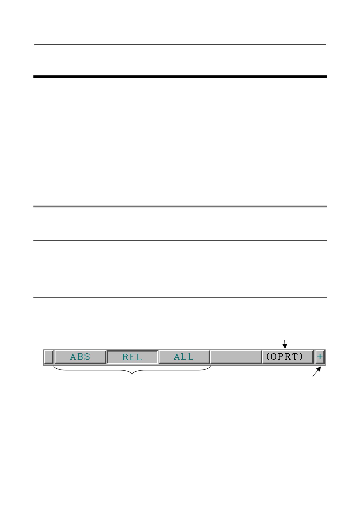
By pressing a function key on the MDI panel, the chapter selection soft keys that belong to the
function are displayed.
Example 1)
Operation selection key
Chapter selection soft keys
Continuous menu key
2
When one of the chapter selection soft keys is pressed, the screen of the chapter is displayed. If the
soft key of a desired chapter is not displayed, press the continuous menu key.
In a chapter, a further choice may be made from multiple chapters.
3
When the screen of a desired chapter is displayed, press the operation selection key to display
operations (operation selection soft keys). If address/numeric keys are used, operation selection
soft keys may be displayed automatically.
- 1 -
1.DISPLAY AND OPERATION
B-64305EN/03
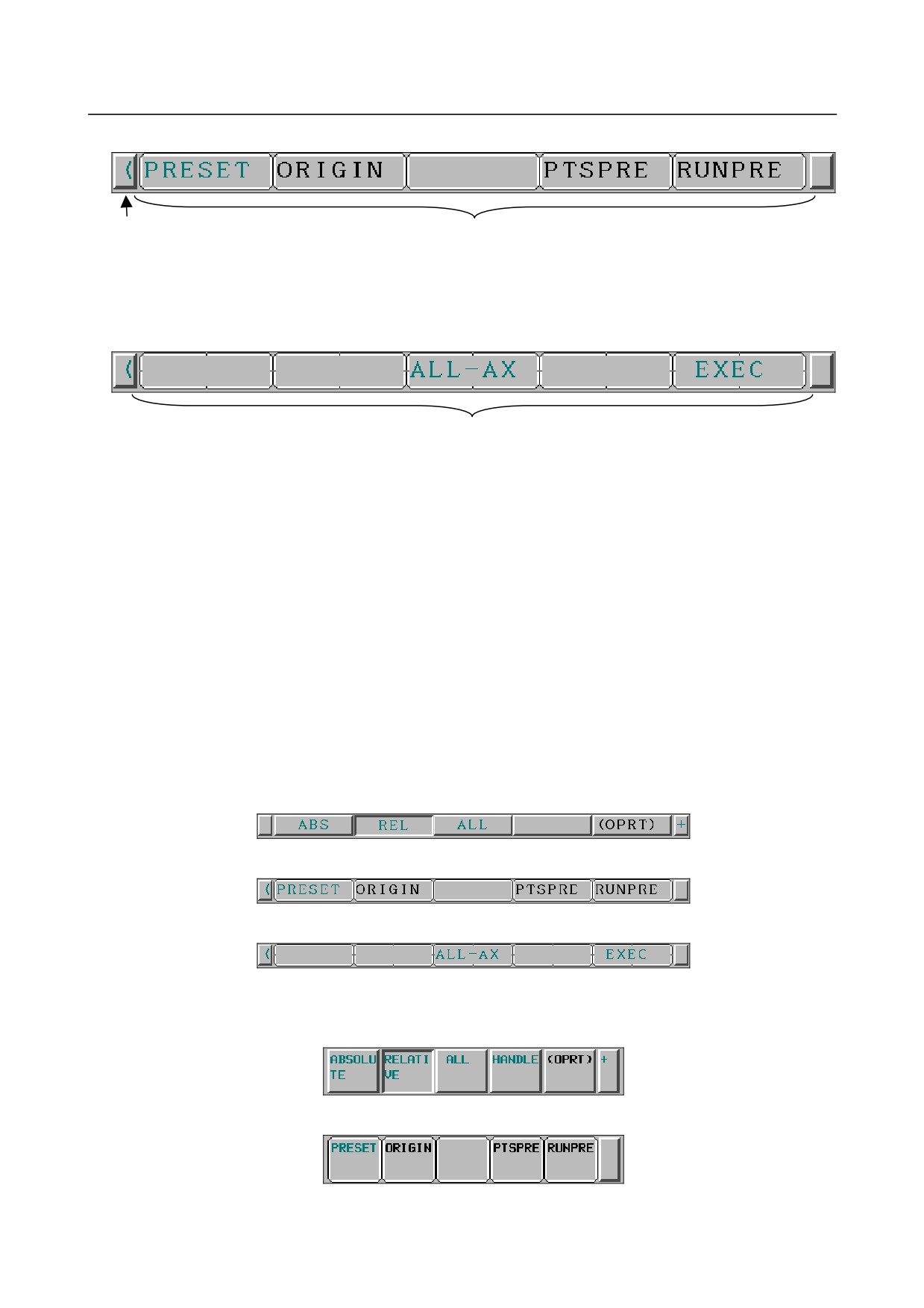
Example 2)
Return menu key
Operation selection soft keys
4
Select a desired operation with the operation selection soft key.
Depending on the operation to be executed, an auxiliary menu of soft keys is displayed. Perform
an operation according to the indications on the auxiliary menu.
Example 3)
Auxiliary menu
5
To return to the display of chapter selection soft keys, press the return menu key.
A general screen display procedure is provided above.
The actual display procedure varies from one screen to another.
For details, see each description of operation.
-
Button design change depending on soft key state
The soft keys to be displayed depend on the object to be selected.
• Chapter selection soft keys
• Operation selection soft keys
• Auxiliary menu of operation selection soft keys
Depending on the state, the button images of the soft keys change.
From the button images, which state the soft keys are assuming can be known.
Example 1)
For the 8.4-inch LCD display unit
Chapter selection soft keys
Operation selection soft keys
Operation selection keys, auxiliary menu
Example 2)
For the 10.4-inch LCD display unit
Chapter selection soft keys
Operation selection soft keys
- 2 -
B-64305EN/03
1.DISPLAY AND OPERATION
Operation selection keys, auxiliary menu
1.1.3
Function Keys
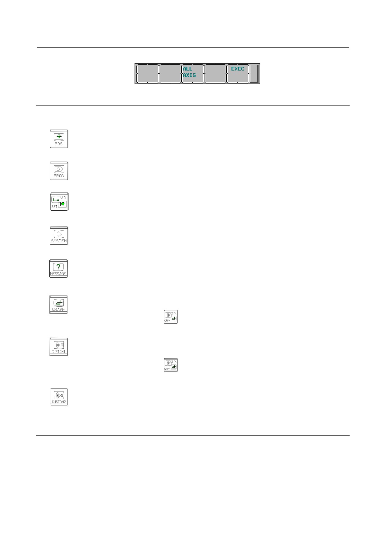
Function keys are provided to select the type of screen to be displayed. The following function keys are
provided on the MDI panel:
Press this key to display the position screen.
Press this key to display the program screen.
Press this key to display the offset/setting screen.
Press this key to display the system screen.
Press this key to display the message screen.
Press this key to display the graphics screen.
For the small MDI unit, press
Press this key to display the custom screen 1 (conversational macro screen or C language
executor screen).
For the small MDI unit, press
Press this key to display the custom screen 2 (conversational macro screen or C language
executor screen).
For the small MDI unit, there is no key that corresponds to this key.
1.1.4
Soft Keys
By pressing a soft key after a function key, the corresponding screen of the function can be displayed.
The chapter selection soft keys of each function are described below.
The four keys on the right-hand side are assigned to chapter selection soft keys. When multiple pages
are used for chapter selection soft keys, [+] is displayed on the continuous menu key (rightmost soft key).
Press the continuous menu key to switch between chapter selection soft keys.
- 3 -
1.DISPLAY AND OPERATION
B-64305EN/03
NOTE
1 Press function keys to switch between screens that are used frequently.
2 Some soft keys are not displayed depending on the option configuration or
parameter setting.
For the 10.4-inch LCD display unit, when pressing other than function key
indicates positional
display on the left side of the screen, the left half of the soft keys are shown below.
or
As for the soft key [MONITOR], refer to the Section III-12.8 in User’s Manual (Common to Lathe
System/Machining Center System).
Refer to the next page for other soft keys.
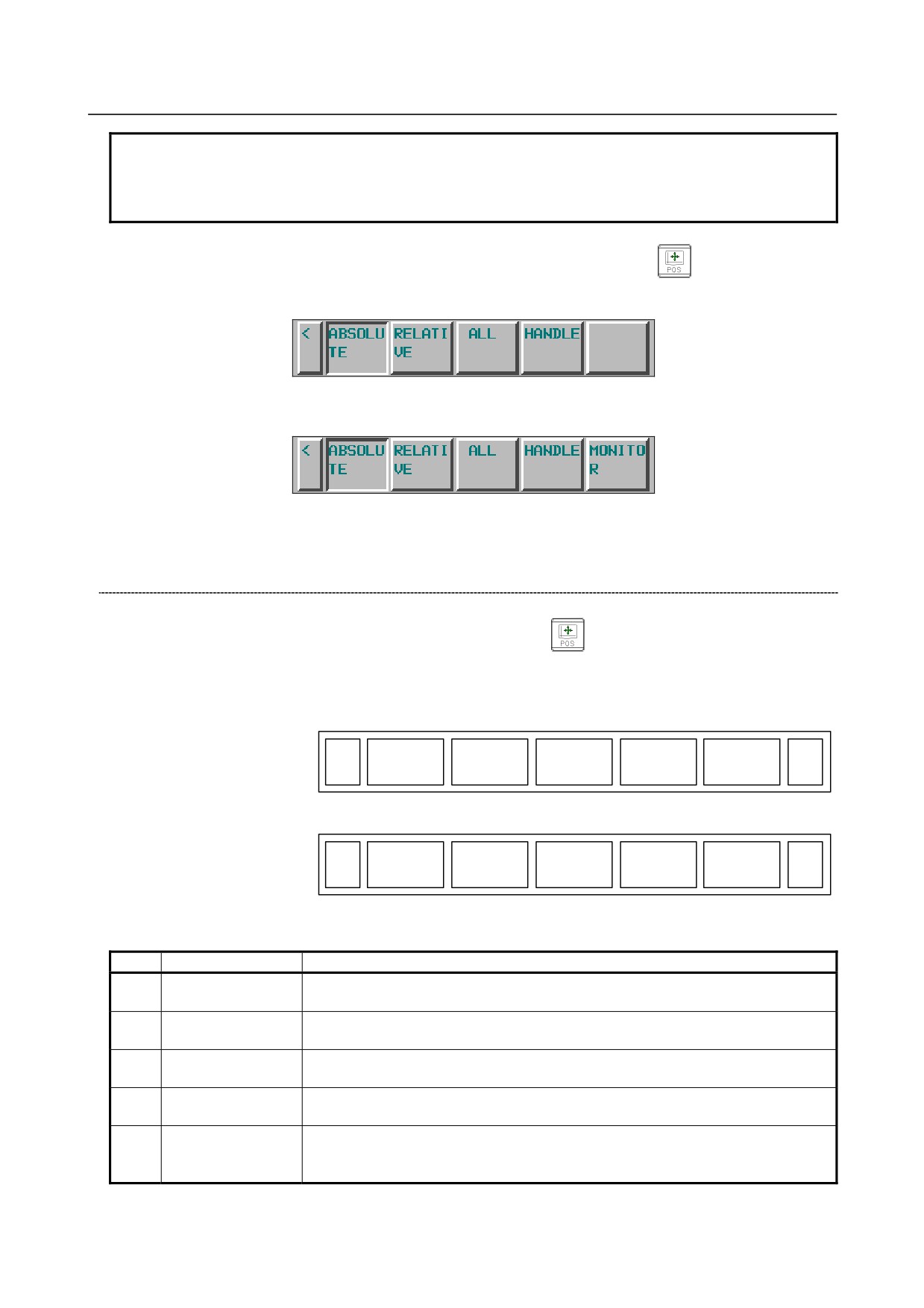
Position display screen
The chapter selection soft keys that belong to the function key
and the function of each screen are
described below.
(1)
(2)
(3)
(4)
(5)
ABS
REL
ALL
HNDL
(OPRT)
+
Page 1
(6)
(7)
(8)
(9)
(10)
MONI
(OPRT)
+
Page 2
Table 1.1.4 (a) Position display screen
No.
Chapter menu
Description
ABS
(1)
Selects the absolute coordinate display screen.
(ABSOLUTE)
REL
(2)
Selects the relative coordinate display screen.
(RELATIVE)
ALL
(3)
Selects the overall coordinate display screen.
(ALL)
HNDL
(4)
Selects the operation screen for manual handle operation.
(HANDLE)
Selects the screen for displaying the servo axis load meter, serial spindle load meter,
MONI
(6)
and speedometer.
(MONITOR)
(Bit 5 (OPM) of Parameter No.3111 = 1 / See Section 1.5)
* The items enclosed by parentheses on the second line under "Chapter menu" are displayed in the
10.4-inch display unit.
- 4 -
B-64305EN/03
1.DISPLAY AND OPERATION
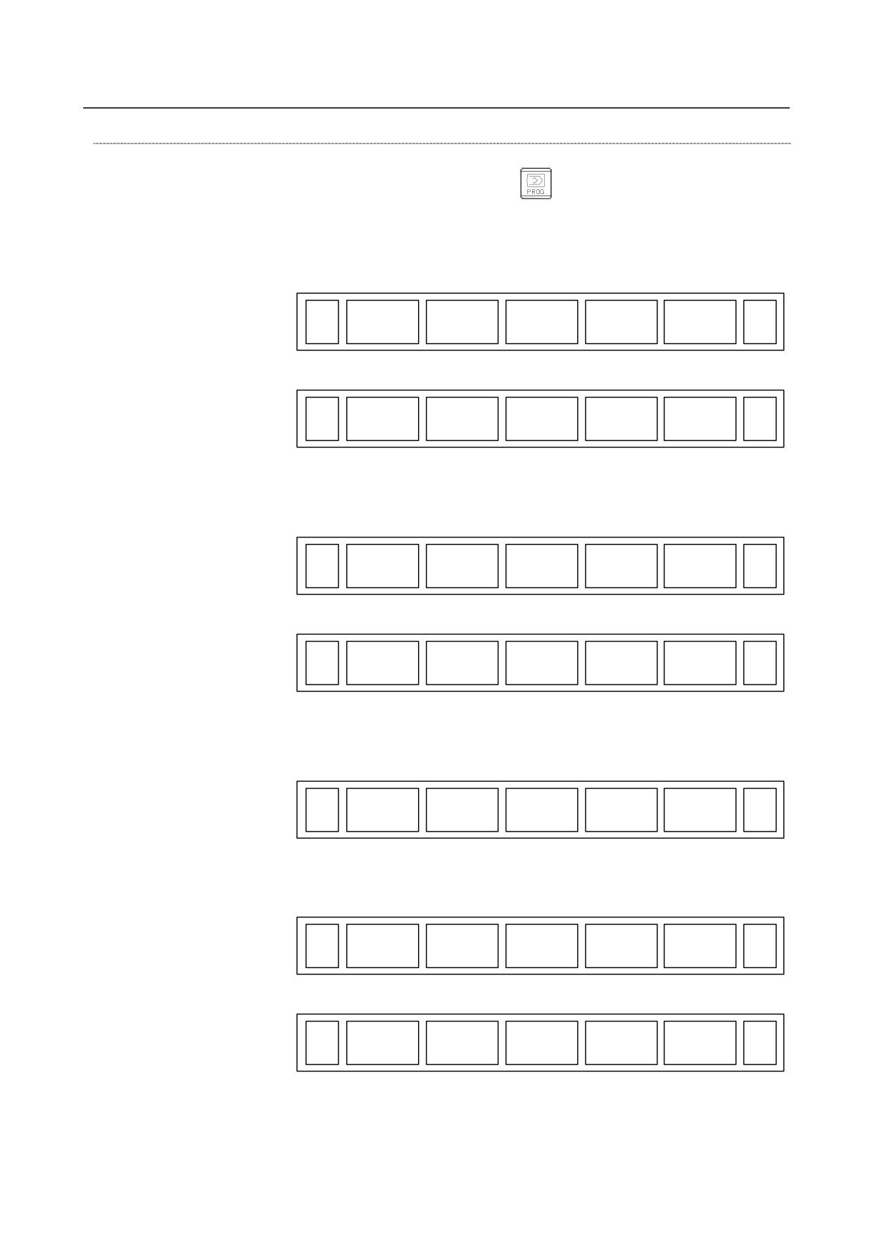
Program screen
The chapter selection soft keys that belong to the function key
and the function of each screen are
described below.
In the MEM/RMT mode
(1)
(2)
(3)
(4)
(5)
PROGRM
CHECK
CURRENT
NEXT
(OPRT)
+
Page 1
(6)
(7)
(8)
(9)
(10)
RESTART
DIR
(OPRT)
+
Page 2
In the MDI mode
(1)
(2)
(3)
(4)
(5)
PROGRM
MDI
CURRENT
NEXT
(OPRT)
+
Page 1
(6)
(7)
(8)
(9)
(10)
RESTART
DIR
(OPRT)
+
Page 2
In the EDIT/TJOG/THND mode
(1)
(2)
(3)
(4)
(5)
PROGRM
DIR
C.A.P
(OPRT)
+
Page 1
In the JOG/HND/REF mode
(1)
(2)
(3)
(4)
(5)
PROGRM
CURRENT
NEXT
(OPRT)
+
Page 1
(6)
(7)
(8)
(9)
(10)
RESTART
DIR
(OPRT)
+
Page 2
- 5 -
1.DISPLAY AND OPERATION
B-64305EN/03
Table 1.1.4 (b) Program
No.
Chapter menu
Description
PROGRM
(1)
Selects the screen for displaying a list of part programs currently registered.
(PROGRAM)
Selects the program check screen for displaying program and axis positions and
(2)
CHECK
modal command values.
(Only for the 8.4- or 10.4-inch display unit used for simultaneous 2-path displays)
MDI
Selects the screen for editing and displaying a program in the MDI mode. (Only in the
(2)
(MDI)
MDI mode)
Selects the screen for displaying the modal command value and the command value
CURRENT
(3)
of the block currently being executed from command values. (Only for the 8.4-inch
display unit)
Selects the screen for displaying the command value of the block currently being
NEXT
(4)
executed and the command value of the block to be executed next from command
(NEXT BLOCK)
values.
C.A.P
Selects the screen for figure conversational input or the screen of MANUAL GUIDE
(4)
(C.A.P)
0i. (Displayed only in the EDIT mode.)
RESTART
(6)
Selects the operation screen for restarting an interrupted program operation.
(RESTART)
(2)
DIR
Selects the screen for displaying a list of part programs currently registered.
(7)
(DIR)
* The items enclosed by parentheses on the second line under "Chapter menu" are displayed in the
10.4-inch display unit.
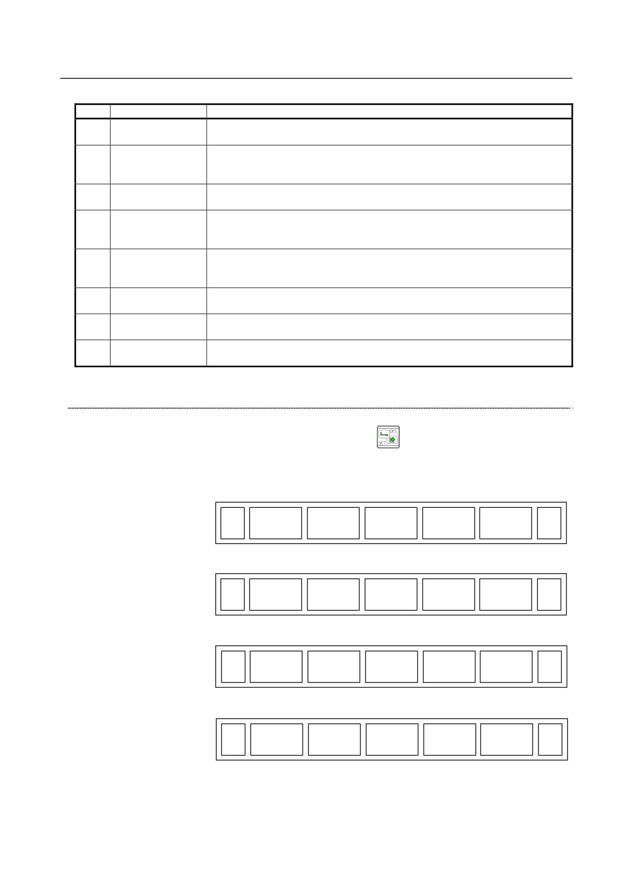
Offset/setting screen
The chapter selection soft keys that belong to the function key
and the function of each screen are
described below.
(1)
(2)
(3)
(4)
(5)
OFFSET
SETTING
WORK
(OPRT)
+
Page 1
(6)
(7)
(8)
(9)
(10)
MACRO
MENU
OPR
TOOLLF
(OPRT)
+
Page 2
(11)
(12)
(13)
(14)
(15)
OFST.2
W.SHFT
BARRIER
(OPRT)
+
Page 3
(16)
(17)
(18)
(19)
(20)
PR-LEV
(OPRT)
+
Page 4
- 6 -
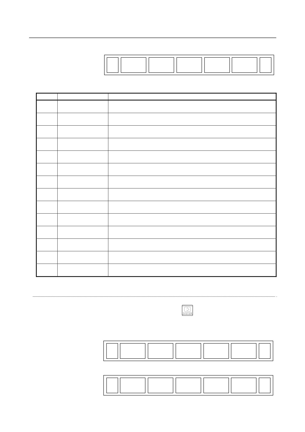
B-64305EN/03
1.DISPLAY AND OPERATION
(21)
(22)
(23)
(24)
(25)
LANG.
PROT.
GUARD
(OPRT)
+
Page 5
Table 1.1.4 (c) Offset
No.
Chapter menu
Description
OFFSET
(1)
Selects the screen for setting tool offset values.
(OFFSET)
SETTING
(2)
Selects the screen for setting the setting parameters.
(SETTING)
WORK
(3)
Selects the screen for setting a workpiece coordinate system offset.
(WORK)
MACRO
(6)
Selects the screen for setting macro variables.
(MACRO)
MENU
(7)
Selects the screen for setting pattern data. (Pattern data input)
(PATTERN MENU)
OPR
Selects the screen for operating part of the operation switches on the machine
(8)
(OPERAT PANEL)
operator's panel as soft switches on the CNC screen. (Software operator's panel)
TOOLLF
(9)
Selects the screen for setting tool life data.
(TOOL LIFE)
OFST.2
(11)
Selects the screen for setting Y-axis offsets. (Only for the T series)
(Y OFFSET)
W.SHFT
Selects the screen for setting workpiece coordinate system shift values. (Only for
(12)
(WORK SHIFT)
the T series)
BARRIER
(14)
Selects the chuck tail stock barrier screen. (Only for the T series)
(BARRIER)
PR-LEV
Selects the screen for setting precision levels. (Machining condition selection
(17)
(PRECI LEVEL)
function)
LANG.
(22)
Selects the screen for setting a display language.
(LANGUAGE)
PROT.
(23)
Selects the screen for setting 8-level data protection.
(PROTECT)
GUARD
(24)
Selects the screen for setting wrong operation prevention.
(GUARD)
* The items enclosed by parentheses on the second line under "Chapter menu" are displayed in the
10.4-inch display unit.
System screen
The chapter selection soft keys that belong to the function key
and the function of each screen are
described below.
(1)
(2)
(3)
(4)
(5)
PARAM
DGNOS
SYSTEM
(OPRT)
+
Page 1
(6)
(7)
(8)
(9)
(10)
PITCH
SV.SET
SP.SET
(OPRT)
+
Page 2
- 7 -
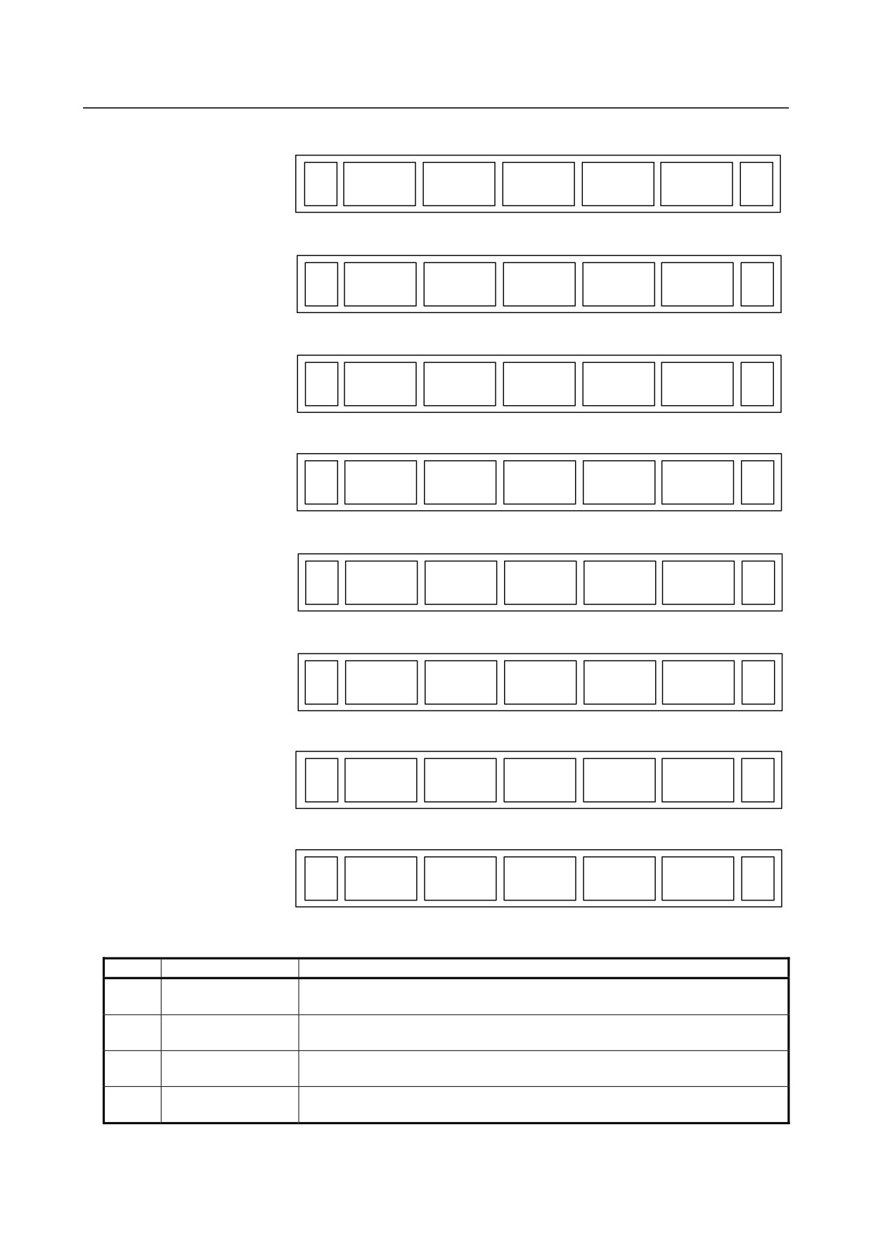
1.DISPLAY AND OPERATION
B-64305EN/03
(11)
(12)
(13)
(14)
(15)
W.DGNS
ALL IO
OPEHIS
+
Page 3
(16)
(17)
(18)
(19)
(20)
PMCMNT
PMCLAD
PMCCNF
PM.MGR
(OPRT)
+
Page 4
(21)
(22)
(23)
(24)
(25)
COLOR
MAINTE
M-INFO
(OPRT)
+
Page 5
(26)
(27)
(28)
(29)
(30)
FSSB
PRMSET
(OPRT)
+
Page 6
(31)
(32)
(33)
(34)
(35)
EMBED
PCMCIA
ETHBRD
FL-net
(OPRT)
+
Page 7
(36)
(37)
(38)
(39)
(40)
RMTDIAG
M-TUN
(OPRT)
+
Page 8
(41)
(42)
(43)
(44)
(45)
ID-INF
MEMORY
(OPRT)
+
Page 9
(46)
(47)
(48)
(49)
(50)
PROF.M
PROF.S
DNET M
DNET S
(OPRT)
+
Page 10
Table 1.1.4 (d) System
No.
Chapter menu
Description
PARAM
(1)
Selects the screen for setting parameters.
(PARAMETER)
DGNOS
(2)
Selects the screen for displaying CNC state. (See Section 1.3)
(DIAGNOSIS)
SYSTEM
(4)
Selects the screen for displaying the current system status.
(SYSTEM)
PITCH
(7)
Selects the screen for setting pith error compensation.
(PITCH ERROR)
- 8 -

B-64305EN/03
1.DISPLAY AND OPERATION
No.
Chapter menu
Description
SV.SET
(8)
Selects the screen for setting the servo-related parameters. (See Section 8.3)
(SERVO SETTING)
SP.SET
(9)
Selects the screen for spindle-related setting. (See Section 9.1.2)
(SPINDLE SETTING)
W.DGNS
Selects the screen for displaying data such as servo positional deviation values,
(11)
(WAVE DIAG)
torque values, machine signals, and so forth as graphs. (See Section 1.6)
ALL IO
(12)
Selects the screen for inputting or outputting data.
(ALL IO)
OPEHIS
Selects the screen for displaying the history of operations performed by the
(14)
(OPERAT HISTRY)
operator and issued alarms.
PMCMNT
Selects the screen related to PMC maintenance such as PMC signal state
(16)
(PMC MAINTE)
monitoring and tracing, and PMC parameter display/editing. (See Section 6.4)
PMCLAD
(17)
Selects the screen related to ladder display/editing. (See Section 6.5)
(PMC LADDER)
PMCCNF
Displays the screen for displaying/editing data other than ladders that makes up a
(18)
(PMC CONFIG)
sequence program and for setting the PMC function.
PM.MGR
(19)
Select the screen of Power Mate CNC Manager. (See Section 1.8)
(P.MATEMGR.)
COLOR
(21)
Selects the screen for setting colors to be used on the screen. (See Section 1.7)
(COLOR)
MAINTE
(22)
Selects the screen for setting maintenance items to be managed periodically.
(PERIOD MAINTE)
M-INFO
Selects the screen for displaying information about maintenance performed. (See
(23)
(MAINTE INFO)
Section 1.9)
FSSB
Selects the screen for making settings related to the high-speed serial servo bus
(27)
(FSSB)
(FSSB: Fanuc Serial Servo Bus). (See Section 8.2)
PRMSET
(28)
Selects the screen for setting parameters necessary for start-up and tuning.
(PARAMETER)
EMBED
Selects the screen for making settings related to the embedded Ethernet
(31)
(EMBED PORT)
(embedded port).
PCMCIA
Selects the screen for making settings related to the embedded Ethernet (PCMCIA
(32)
(PCMCIA LAN)
Ethernet card).
ETHBRD
(33)
Selects the screen for making settings related to the fast Ethernet/fast data server.
(ETHER BOARD)
FL-net
(34)
Selects the screen for making settings related to FL-net.
(FL-net)
RMTDIAG
(36)
Selects the screen for making settings related to remote diagnosis.
(REMOTE DIAG)
M-TUN
Displays the screen for setting the parameter set for emphasis on speed (LV1) or
(37)
(MCHN TUNING)
emphasis on precision (LV10).
MEMORY
(43)
Selects the screen for displaying the contents of memory.
(MEMORY)
PROF.M
(46)
Selects the screen for making settings related to the Profibus master function.
(PROFI MASTER)
PROF.S
(47)
Selects the screen for making settings related to the Profibus slave function.
(PROFI SLAVE)
DNET M
(48)
Selects the screen for making settings related to the DeviceNet master function.
(DEVNETMASTER)
DNET S
(49)
Selects the screen for making settings related to the DeviceNet slave function.
(DEVNETSLAVE)
* The items enclosed by parentheses on the second line under "Chapter menu" are displayed in the
10.4-inch display unit.
- 9 -
1.DISPLAY AND OPERATION
B-64305EN/03
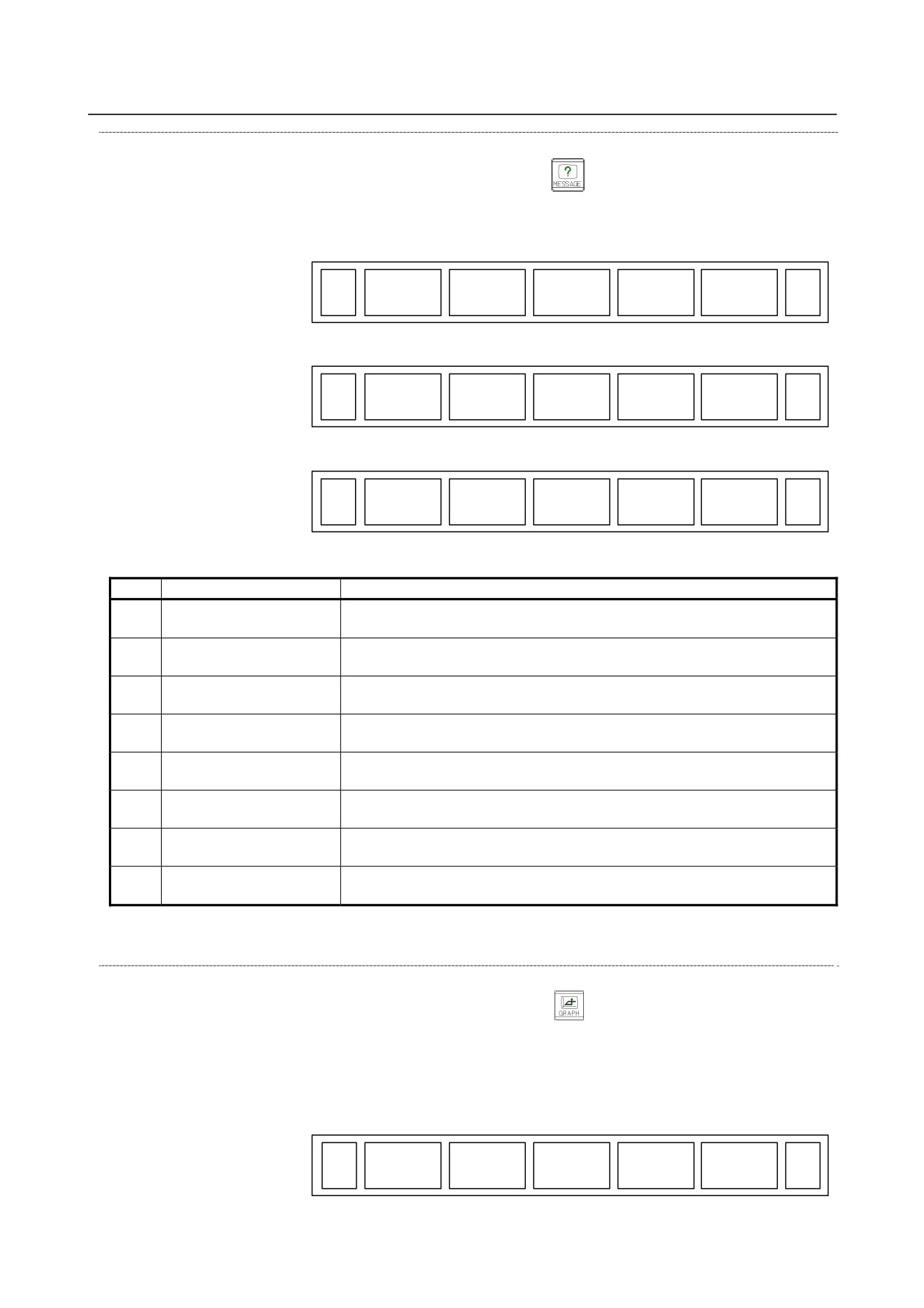
Message screen
The chapter selection soft keys that belong to the function key
and the function of each screen are
described below.
(1)
(2)
(3)
(4)
(5)
ALARM
MSG
HISTRY
+
Page 1
(6)
(7)
(8)
(9)
(10)
MSGHIS
+
Page 2
(11)
(12)
(13)
(14)
(15)
EMB LOG
PCM LOG
BRD LOG
FL-net
+
Page 3
Table 1.1.4 (e) Message
No.
Chapter menu
Description
ALARM
(1)
Selects the alarm message screen. (See Appendix A, "ALARM LIST")
(ALARM)
MSG
(2)
Selects the operator message screen.
(MESSAGE)
HISTRY
(3)
Selects the screen for displaying the details of alarms issued so far.
(HISTRY)
MSGHIS
Selects the external operator message screen.
(7)
(MESAGE HISTRY)
(Bit 2 (OMH) of Parameter No.3112)
EMB LOG
Selects the screen for displaying error messages related to the embedded
(11)
(EMBED LOG)
Ethernet (embedded port).
PCM LOG
Selects the screen for displaying error messages related to the embedded
(12)
(PCMCIA LOG)
Ethernet (PCMCIA Ethernet card).
BRD LOG
Selects the screen for displaying error messages related to the fast
(13)
(BOARD LOG)
Ethernet/fast data server.
FL-net
(14)
Selects the screen for displaying error messages related to the FL-net.
(FL-net MSG)
* The items enclosed by parentheses on the second line under "Chapter menu" are displayed in the
10.4-inch display unit.
Graphic screen
The chapter selection soft keys that belong to the function key
and the function of each screen are
described below.
When the graphic display function is enabled:
(1)
(2)
(3)
(4)
(5)
PARAM
GRAPH
GRAPH
LARGE
(OPRT)
- 10 -
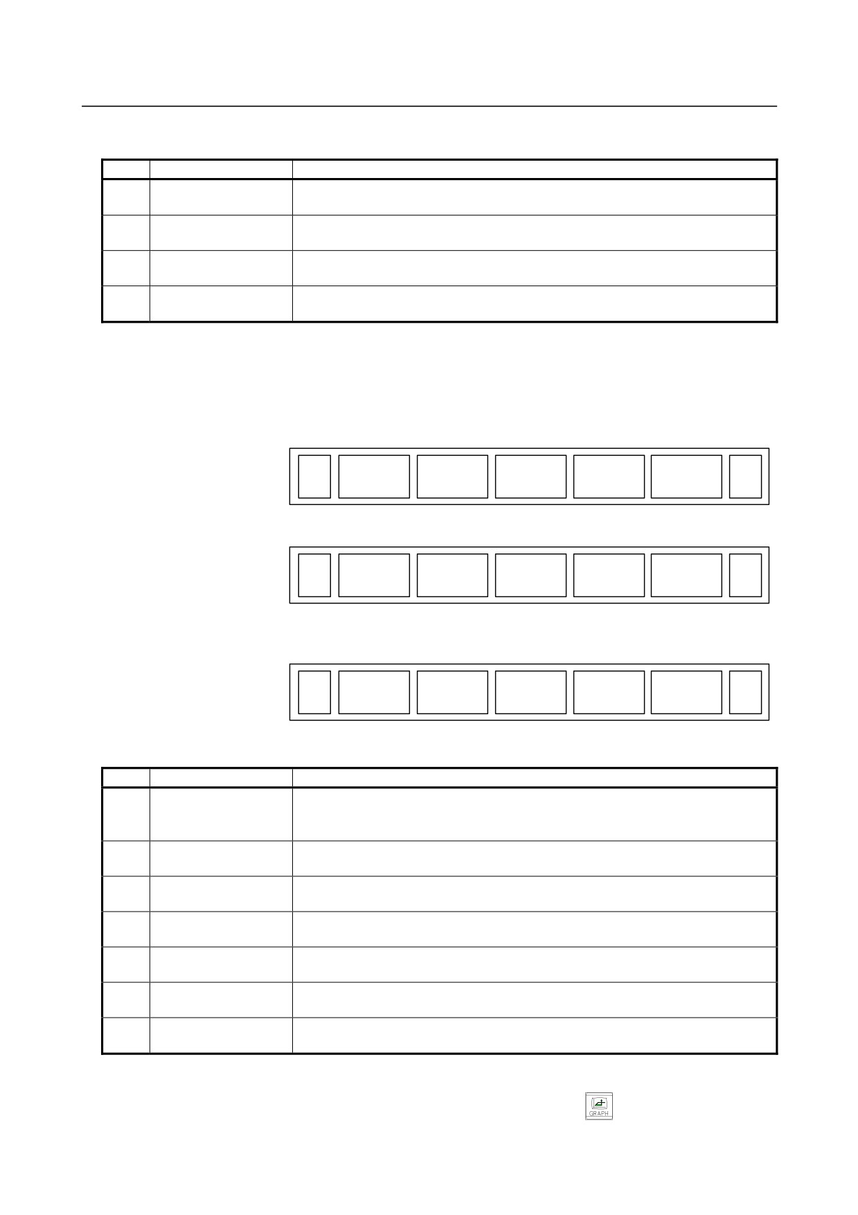
B-64305EN/03
1.DISPLAY AND OPERATION
Table 1.1.4 (f) Graphic
No.
Chapter menu
Description
PARAM
(1)
Selects the screen for setting graphic parameters.
(PARAMETER)
GRAPH
Selects the screen for performing the graphic display of tool paths. (For the M
(2)
(GRAPH)
series system)
GRAPH
Selects the screen for performing the graphic display of tool paths. (For the T series
(3)
(GRAPH)
system)
LARGE
(4)
Displays the soft key for setting the scaling factor of graphic display.
(LARGE)
* The items enclosed by parentheses on the second line under "Chapter menu" are displayed in the
10.4-inch display unit.
When the dynamic graphic display function is enabled
M series :
(1)
(2)
(3)
(4)
(5)
PARAM
EXEC
EXEC
POS
(OPRT)
+
(6)
(7)
(8)
(9)
(10)
PARAM
3-PLN
(OPRT)
+
T series :
(6)
(7)
(8)
(9)
(10)
PARAM
GRAPH
LARGE
(OPRT)
Table 1.1.4 (g) Graphic (for dynamic graphic)
No.
Chapter menu
Description
(1)
PARAM
(6)
Selects the screen for setting drawing parameters.
(PARAMETER)
(11)
EXEC
(2)
Selects the screen for drawing tool paths.
(EXEC)
EXEC
(3)
Selects the screen for drawing animation.
(EXEC)
POS
Selects the screen for displaying tool positions on tool paths during drawing tool
(4)
(POSITION)
paths.
3-PLN
(7)
Selects the screen for displaying 3-plane drawings in animated simulation.
(3-PLN)
GRAPH
(13)
Selects the screen for performing the graphic display of tool paths.
(GRAPH)
LARGE
(14)
Displays the soft key for setting the scaling factor of graphic display.
(LARGE)
*1 The items enclosed by parentheses on the second line under "Chapter menu" are displayed in the
10.4-inch display unit.
*2 Item (2) and item (3) are displayed alternately each time function key
is pressed.
- 11 -
1.DISPLAY AND OPERATION
B-64305EN/03
1.2
SYSTEM CONFIGURATION SCREEN
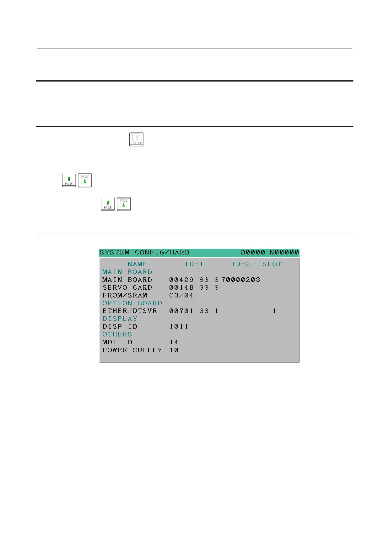
After the system has started normally, you can find the types of installed hardware and software types by
displaying a system configuration screen.
1.2.1
Display Method
1
Press the function key
to display the screen for parameters and other data.
2
Pressing the soft key [SYSTEM] causes a system configuration screen to appear.
3
Two types of system configuration screen, the hardware configuration screen and software
configuration screen, are provided, and you can switch between these screens by using the
page keys.
When all information cannot be displayed on one page of the screen, you can switch to the next page
by using the
keys.
1.2.2
Hardware Configuration Screen
-
Screen display
-
Displayed information
The following explains the displayed information:
1.
NAME
MAIN BOARD
•
Displays information on the main board, and cards and modules on the main board.
OPTION BOARD
•
Displays information on the board installed in the option slot.
DISPLAY
•
Displays information on the display unit.
OTHERS
•
Displays information on other components (such as an MDI and a basic unit).
2.
ID-1, ID-2
•
Displays the ID of each hardware component. For the details of the hardware ID, see section
2.5 or section 3.5.
3.
SLOT
•
Displays the number of the slot in which the option board is inserted.
- 12 -
B-64305EN/03
1.DISPLAY AND OPERATION
1.2.3
Software Configuration Screen
-
Screen display
-
Displayed information
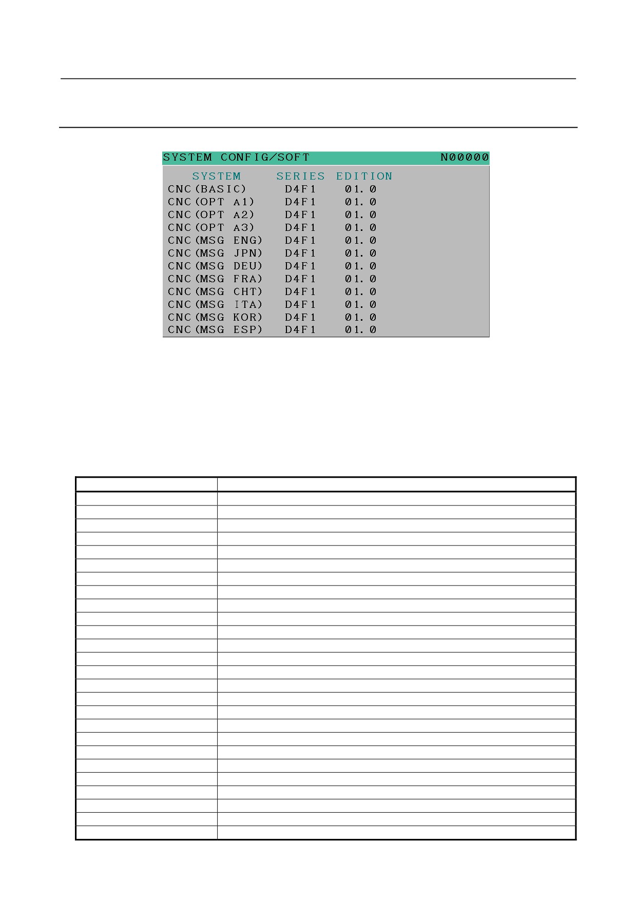
The following explains the displayed information:
SYSTEM :
Software type
SERIES:
Software series
EDITION:
Software edition
-
Displayed systems and corresponding software types
The following lists the correspondence between displayed systems and software:
System
Software type
CNC(BASIC)
CNC basic software
CNC(OPT A1)
Option assembly A1
CNC(OPT A2)
Option assembly A2
CNC(OPT A3)
Option assembly A3
CNC(MSG ENG)
Language indication (English)
CNC(MSG JPN)
Language indication (Japanese)
CNC(MSG DEU)
Language indication (German)
CNC(MSG FRA)
Language indication (French)
CNC(MSG CHT)
Language indication (Chinese (traditional characters))
CNC(MSG ITA)
Language indication (Italian)
CNC(MSG KOR)
Language indication (Korean)
CNC(MSG ESP)
Language indication (Spanish)
CNC(MSG NLD)
Language indication (Dutch)
CNC(MSG DAN)
Language indication (Danish)
CNC(MSG PTG)
Language indication (Portuguese)
CNC(MSG PLK)
Language indication (Polish)
CNC(MSG HUN)
Language indication (Hungarian)
CNC(MSG SVE)
Language indication (Swedish)
CNC(MSG CSY)
Language indication (Czech)
CNC(MSG CHS)
Language indication (Chinese (simplified characters))
CNC(MSG RUS)
Language indication (Russian)
CNC(MSG TRK)
Language indication (Turkish)
BOOT
Boot system
PMC(SYSTEM)
PMC function
PMC(LADDER1)
PMC ladder
SERVO
Digital servo software
- 13 -