FANUC Series 0i-MODEL C, Series 0i Mate-MODEL C. MAINTENANCE MANUAL - page 16
7. AC SPINDLE (SERIAL INTERFACE)
B-64115EN/02
7.1.2
Spindle Setting and
Tuning Screen
7.1.2.1
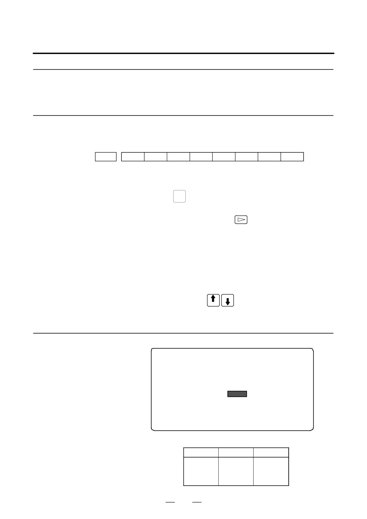
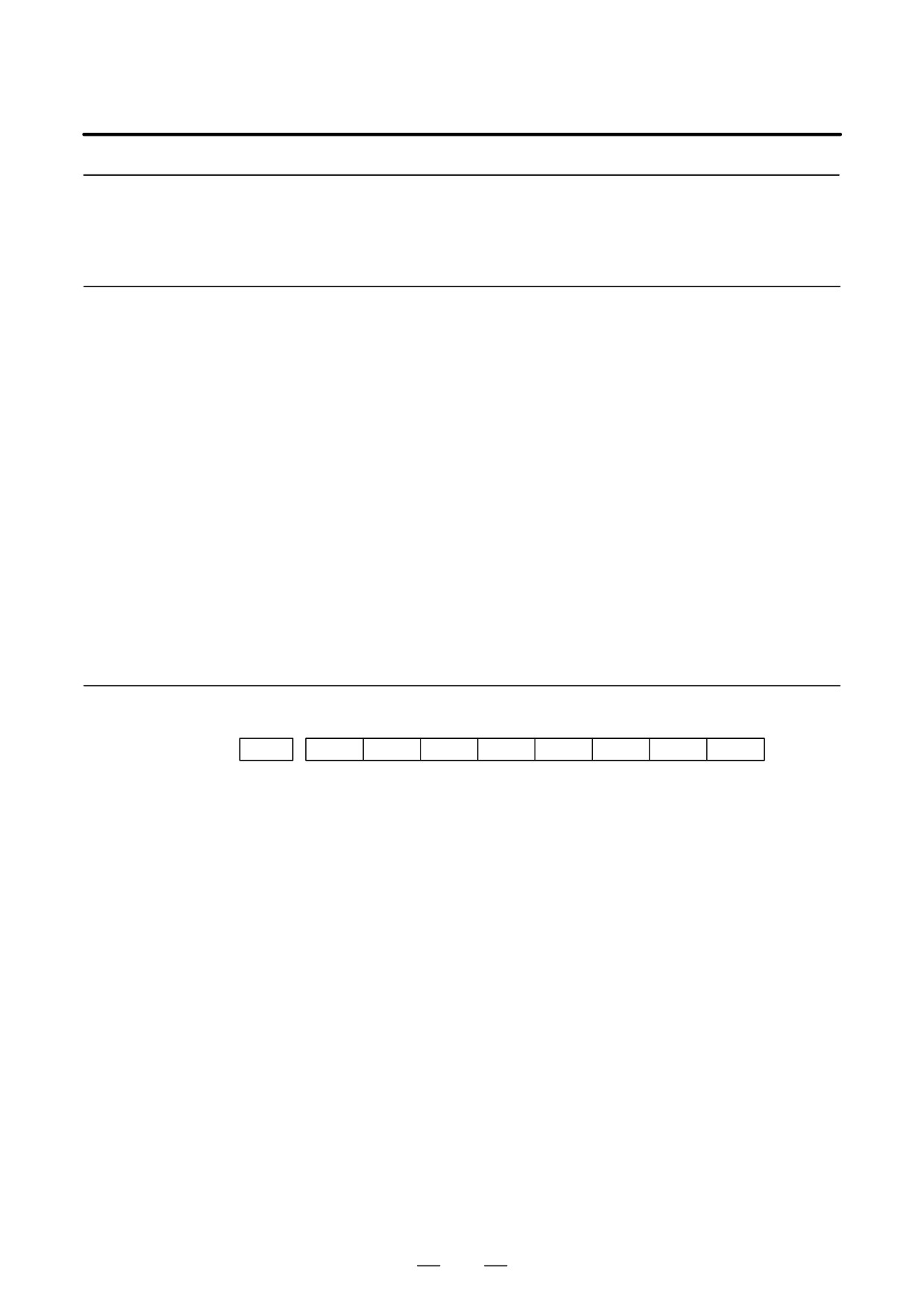
(1) Confirm the parameters
Display method
#7
#6
#5
#4
#3
#2
#1
#0
3111
SPS
Bit1 (SPS)
0 : The spindle tuning screen is not displayed.
l
1 : The spindle tuning screen is displayed.
(2) Press the
SYSTEM
key to select the screen for setting parameters and other
data.
(3) Press the continuous menu key
(4) Press the soft key [SP.PRM]. Then, the spindle setting and tuning
screen appears.
(5) The following screens are provided. These screens can be selected
using soft keys.
1) [SP.SET] : Spindle setting screen
2) [SP.TUN] : Spindle tuning screen
3) [SP.MON] : Spindle monitor screen
PAGE
(6) With the page keys
, a spindle to be displayed can be
PAGE
selected (only when multiple serial spindles are connected).
7.1.2.2
Spindle setting screen
SPINDLE SETTING
(1)GEAR SELECT
: 1
(2)SPINDLE
: S11
(PARAMETER)
(3)GEAR RATIO
50
(4)MAX SPINDLE SPEED
3000
(5)MAX MOTOR SPEED
6000
(6)MAX C AXIS SPEED
100
D Gear selection
The gear select status on the machine side is displayed.
Indication
CTH1
CTH2
1
0
0
2
0
1
3
1
0
4
1
1
430
7. AC SPINDLE (SERIAL INTERFACE)
B-64115EN/02
D Spindle
Select a spindle for which data is to be set.
S11: Main spindle amplifier for the 1st spindle
S12: Subspindle amplifier for the 1st spindle
S21: Main spindle amplifier for the 2nd spindle
S22: Subspindle amplifier for the 2nd spindle
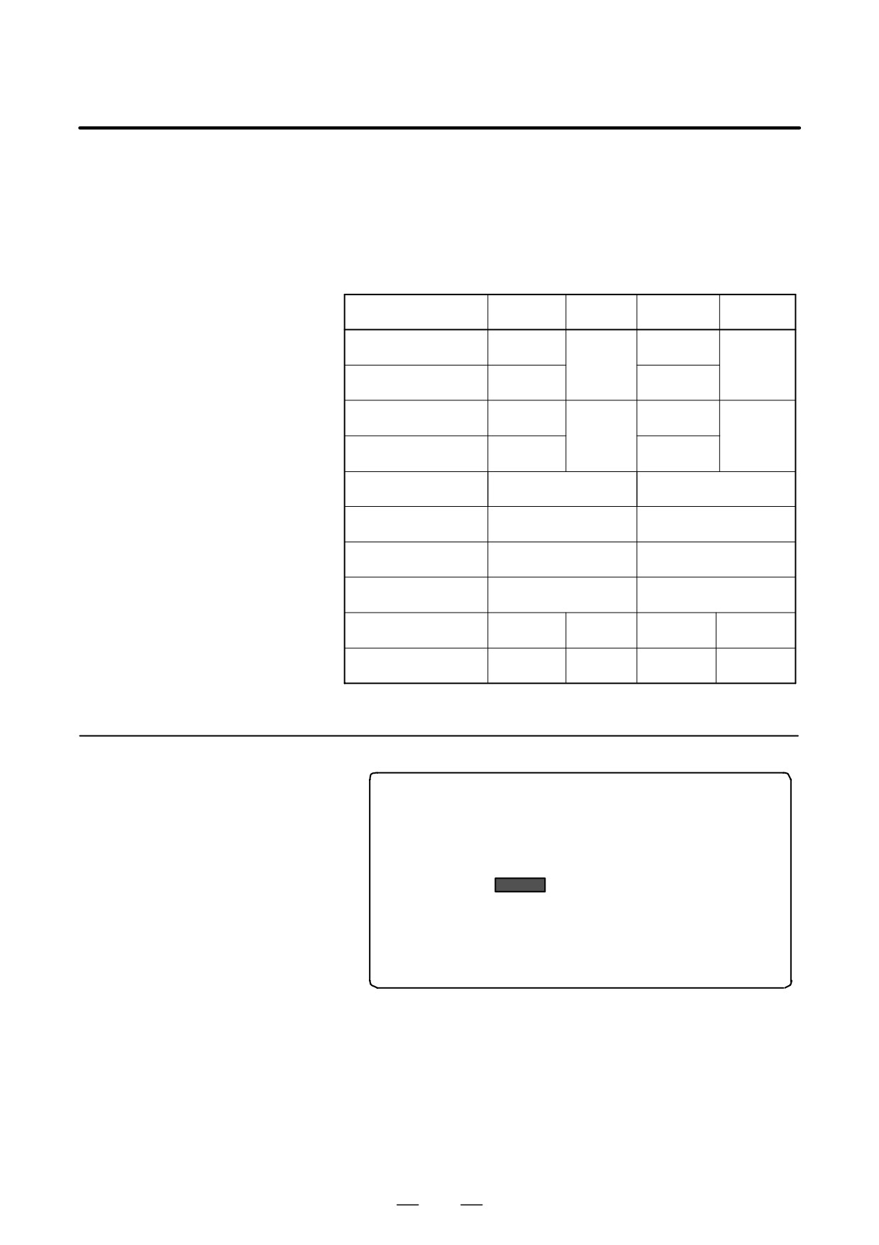
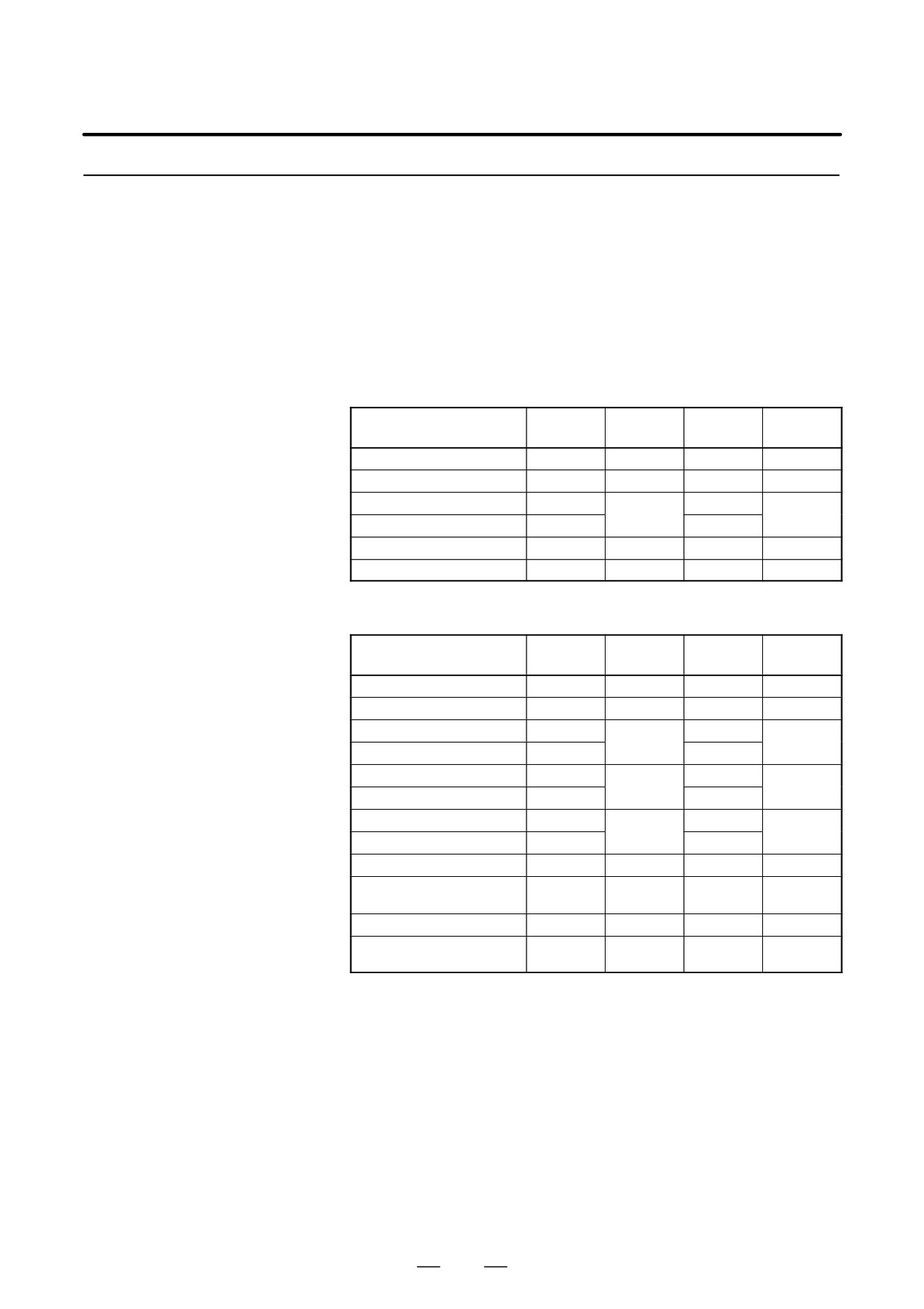
D Parameters
S11:1st Main
S12:1st Sub
S21:2nd Main
S22:2nd Sub
Gear ratio(HIGH)
4056
4056
4216
4216
Gear ratio(MIDIUM HIGH)
4057
4057
Gear ratio(MIDIUM LOW)
4058
4058
4217
4217
Gear ratio(LOW)
4059
4059
Max. spindle speed
3741
3741
(gear1)
Max. spindle speed
3742
3742
(gear2)
Max. spindle speed
3743
3743
(gear3)
Max. spindle speed
3744
3744
(gear4)
Max. motor speed
4020
4196
4020
4196
Max. C axis speed
4021
None
4021
None
7.1.2.3
Spindle tuning screen
SPINDLE TUNING
OPERATION
: SPEED CONTROL
GEAR SELECT
: 1
SPINDLE
: S11
(PARAMETER)
(MONITOR)
PROP.GAIN
20
MOTOR SPEED
100
INT.GAIN
50
SPINDLE SPEED 150
LOOP GAIN
3000
POS ERR S1
100
MOTOR VOLT
30
POS ERR S2
103
TIME CONST
100
SYN.ERR
3
REF. SHIFT
2046
D Operation mode
1
: Normal operation
2
: Orientation
3
: Synchronization control
4
: Rigid tapping
5
: Cs contour control
6
: Spindle positioning control
431
7. AC SPINDLE (SERIAL INTERFACE)
B-64115EN/02
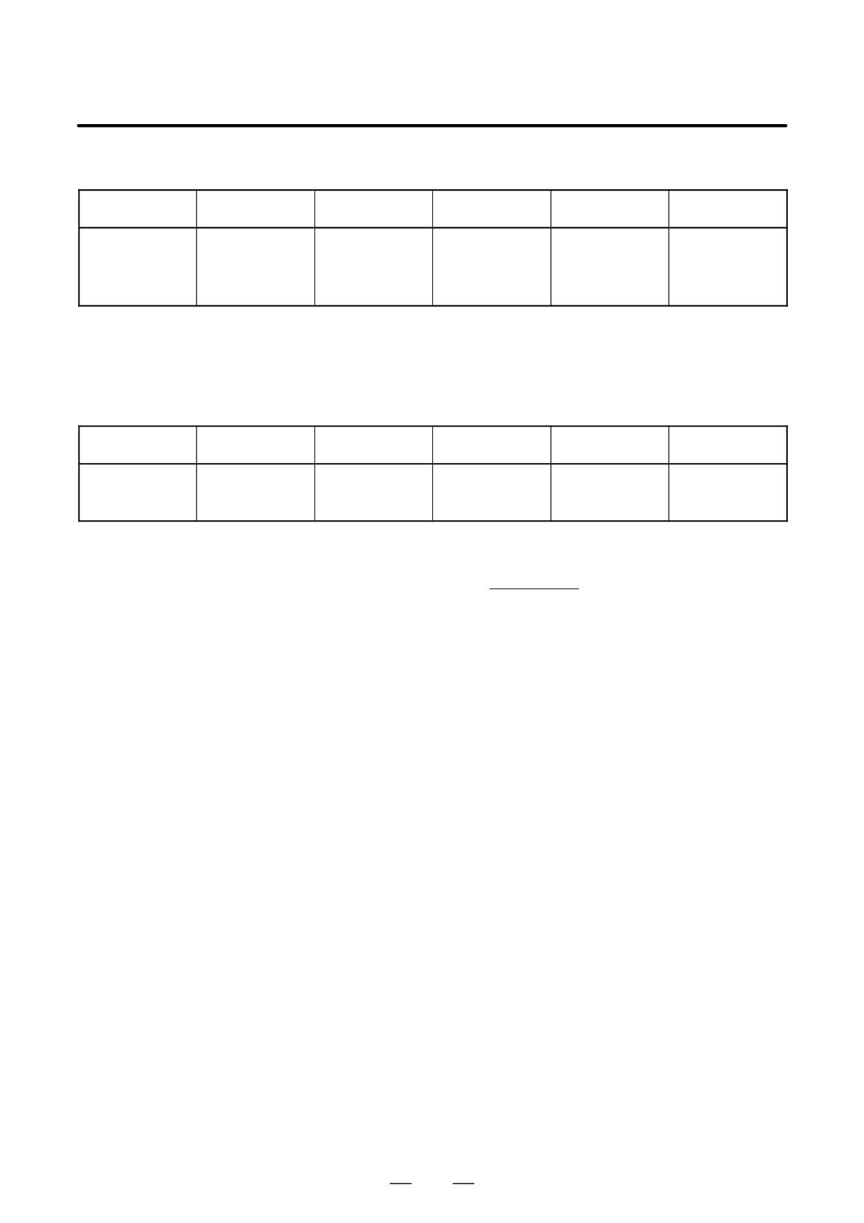
D Displayed parameters
The displayed parameters vary depending on the operation mode.
Spindle position-
Normal
Synchronization
Cs contour
Orientation
Rigid tapping
ing control
operation
control
control
Proportional gain
Proportional gain
Proportional gain
Proportional gain
Proportional gain
Proportional gain
Integral gain
Integral gain
Integral gain
Integral gain
Integral gain
Integral gain
Loop gain
Motor voltage
Loop gain
Loop gain
Loop gain
Loop gain
Motor voltage
Regenerative power
Motor voltage
Motor voltage
Motor voltage
Motor voltage
ZRN gain (%)
ORAR gain (%)
Acceleration/deceleration
ZRN gain
ZRN gain (%)
Shift reference position
Shift spindle stop position
constant (%)
Shift reference position
Shift reference position
Shift reference position
Shift reference position
Note) For the parameter numbers corresponding to the displayed
parameter items, see Section 7.1.2.5.
D Displayed monitoring
The displayed monitoring items vary depending on the operation mode.
items
Spindle position-
Normal
Synchronization
Cs contour
Orientation
Rigid tapping
ing control
operation
control
control
Motor speed
Motor speed
Motor speed
Motor speed
Motor speed
Motor speed
Feedrate
Spindle speed
Spindle speed
Spindle speed
Spindle speed
Spindle speed
Position deviation S1
Position deviation S1
Position deviation S1
Position deviation S1
Position deviation S1
Position deviation S2
Position deviation Z
Synchronous deviation
Synchronous deviation
Note 1)
|Spindle data|
Motor speed [min*1] +
Max. Motor speed.(* 1)
16383
(*1) Parameter 4020: Main spindleParameter 4196: Subspindle
Note 2) The spindle speed in Cs contour control mode is in degrees/min.
432

7. AC SPINDLE (SERIAL INTERFACE)
B-64115EN/02
7.1.2.4
Spindle monitor screen
SPINDLE MONITOR SCREEN
ALARM
: AL-27(POSITION CODER DIS.)
OPERATION
: Cs AXIS OONTROL
SPINDLE SPEED : 100 DEG/MIN
MOTOR SPEED
: 150 RPM
0
50
100
150
200
LOAD METER (%)
JJJJJ
CONTROL INPUT : ORCM MRDY *ESP
CONTROL OUTPUT : SST SDT ORAR
D Spindle alarm
1: Motor overheated
2: Speed deviation excessive
3: Fuse blow of DC link
4: Fuse blow of AC inputline
5: Fuse blow of DC voltage
7: Excessive speed
9: Heat sink overheat
10: Low voltage of AC input
11: Excess voltage in DC link
12: Excess current in DC link
13: CPU internal data memory error
18: ROM SUM check error
19: U phase current offset excessive
20: V phase current offset excessive
24: Serial data transmission abnormal
25: Serial data transmission stop
26: Cs axis speed detecting signal failure
27: Position coder signal disconnection
28: Cs pos.detect signal disconnection
29: Short time overload
30: Input circuit excess current
31: Speed detecting signal disconnection
32: SLC LSI internal RAM abnormal
33: DC link charging insufficient
34: Parameter abnormal setting
35: Gear ratio data excessive
36: Error counter overflow
37: Speed detecting unit error setting
38: Magnetic sensor signal abnormal
39: Alarm of one revolution signal for Cs axis control is detected
40: Alarm of one revolution signal for Cs axis control is not detected
41: Erroneous detection of the position coder one revolution signal
42: Undetection of the position coder one revolution signal
46: Erroneous detection of the position coder one revolution signal on
threading
47: Abnormal position coder signal
48: Erroneous detection of position coder one revolution signal
433
7. AC SPINDLE (SERIAL INTERFACE)
B-64115EN/02
D Operation
Following 6 modes are available:
a. Normal operation
b. Orientation
c. Synchronous operation
d. Rigid tapping
e. Cs contour cotrol
f. Spindle positioning control
D Load meter
The load meter displays spindle load in a unit of 10%.
1) Load meter[%] +Loadmeterdata
Max.output value
32767
of load meter (*)
(*) PRM 4127: Main
PRM 4274: Sub.
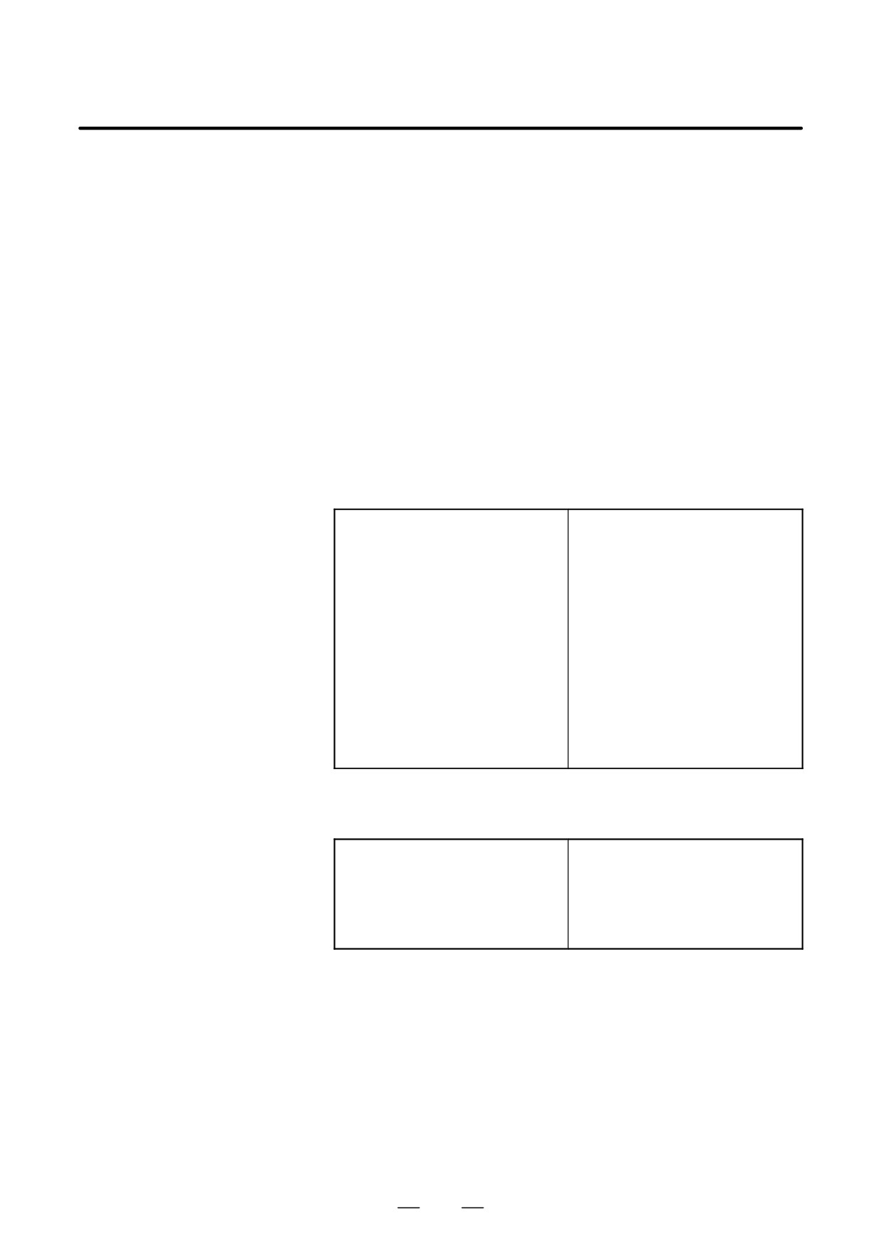
D Control input signal
Max.10 signals those are ON are displayed from the following signals:
TLML
: Torque limit command (low)
SPSL
: Spindle selection signal
TLMH
: Torque limit command (high)
MCFN
: Power line switching
CTH1
: Gear signal 1
SOCN
: Soft start/stop cancel
CTH2
: Gear signal 2
RSL
: Output switching request
SRV
: Spindle reverse rotation
RCH
: Power line state confirm
SFR
: Spindle forward rotation
INDX
: Orientation stop pos.
ORCM
: Spindleorientation
change
MEDY
: Machine ready
ROTA
: Rotation direction of
ARST
: Alarm reset signal
ORCM
*ESP
: Emergency stop
NRRO
: Shor-cut of ORCM
INTG
: Speed integral control
signal
DEFM
: Referencial mode
command
D Control output signals
Max. 10 signals those are ON are displayed from the following signals:
ALM
: Alarm signal
TML5
: Torque limitation
SST
: Speed zero signal
ORAR : Orientation end signal
SDT
: Speed detecting signal
CHP
: Power line switched signal
SAR
: Speed arrival signal
CFIN
: Spindle switch complete
LDT1
: Load detecting signal 1
RCHP
: Output switch signal
LDT2
: Load detecting signal 2
RCFN
: Output switch complete
signal
434
7. AC SPINDLE (SERIAL INTERFACE)
B-64115EN/02
7.1.2.5
Correspondence
between operation mode
and parameters on
spindle tuning screen
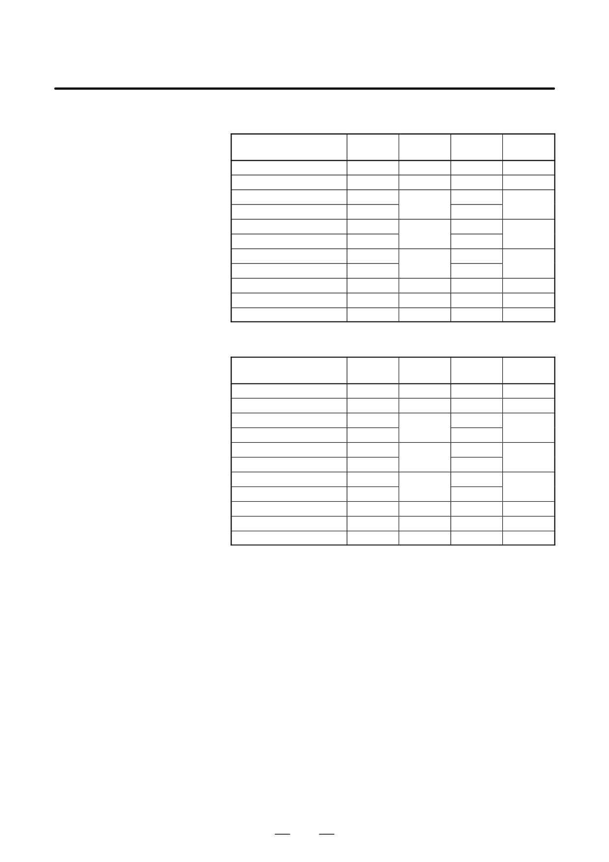
D Normal operation mode
S11:
S12:
S21:
S22:
1st Main
1st Sub
2nd Main
2nd Sub
Proportional gain(HIGH)
4040
4206
4040
4206
Proportional gain (LOW)
4041
4207
4041
4207
Integral gain(HIGH)
4048
4048
4212
4212
Integral gain(LOW)
4049
4049
Motor voltage
4083
4236
4083
4236
Regenerative power
4080
4231
4080
4231
D Orientation mode
S11:
S12:
S21:
S22:
1st Main
1st Sub
2nd Main
2nd Sub
Proportionalgain(HIGH)
4042
4208
4042
4208
Proportional gain (LOW)
4043
4209
4043
4209
Integral gain(HIGH)
4050
4050
4213
4213
Integral gain(LOW)
4051
4051
Loop gain (HIGH)
4060
4060
4218
4218
Loop gain (MID, HIGH)
4061
4061
Loop gain (MID, LOW)
4062
4062
4219
4219
Loop gain (LOW)
4063
4063
Motor voltage
4084
4237
4084
4237
Gain change upon completion
4064
4220
4064
4220
of orientation
Stop position shift
4077
4228
4077
4228
PC-type orientation stop posi-
4031
4204
4031
4204
tion
435
7. AC SPINDLE (SERIAL INTERFACE)
B-64115EN/02
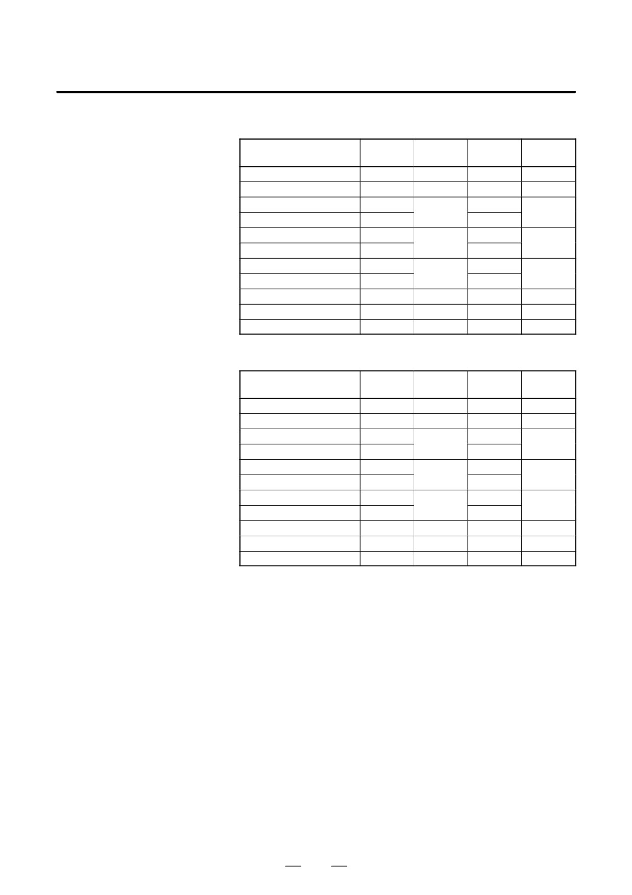
D Synchronization control
Numerals are parameter numbers :
mode
S11:
S12:
S21:
S22:
1st Main
1st Sub
2nd Main
2nd Sub
Proportional gain(HIGH)
4044
4210
4044
4210
Proportionalgain(LOW)
4045
4211
4045
4211
Integral gain(HIGH)
4052
4052
4214
4214
Integral gain(LOW)
4053
4053
Position loop gain(HIGH)
4065
4221
4065
4221
Position loop gain(MID,HIGH)
4066
4066
Position loop gain(MID,LOW)
4067
4222
4067
4222
Position loop gain(LOW)
4068
4068
Motor voltage
4085
4238
4085
4238
Acc./Dec. time constant
4032
4032
Shift amount
4034
4034
D Rigid tapping mode
Numerals are parameter numbers :
S11:
S12:
S21:
S22:
1st Main
1st Sub
2nd Main
2nd Sub
Proportional gain(HIGH)
4044
4210
4044
4210
Proportionalgain(LOW)
4045
4211
4045
4211
Integral gain(HIGH)
4052
4052
4214
4214
Integral gain(LOW)
4053
4053
Position loop gain(HIGH)
4065
4221
4065
4221
Position loop gain(MID,HIGH)
4066
4066
Position loop gain(MID,LOW)
4067
4222
4067
4222
Position loop gain(LOW)
4068
4068
Motor voltage
4085
4238
4085
4238
ZRN gain %
4091
4239
4091
4239
Grid shift amount
4073
4223
4073
4223
436
7. AC SPINDLE (SERIAL INTERFACE)
B-64115EN/02
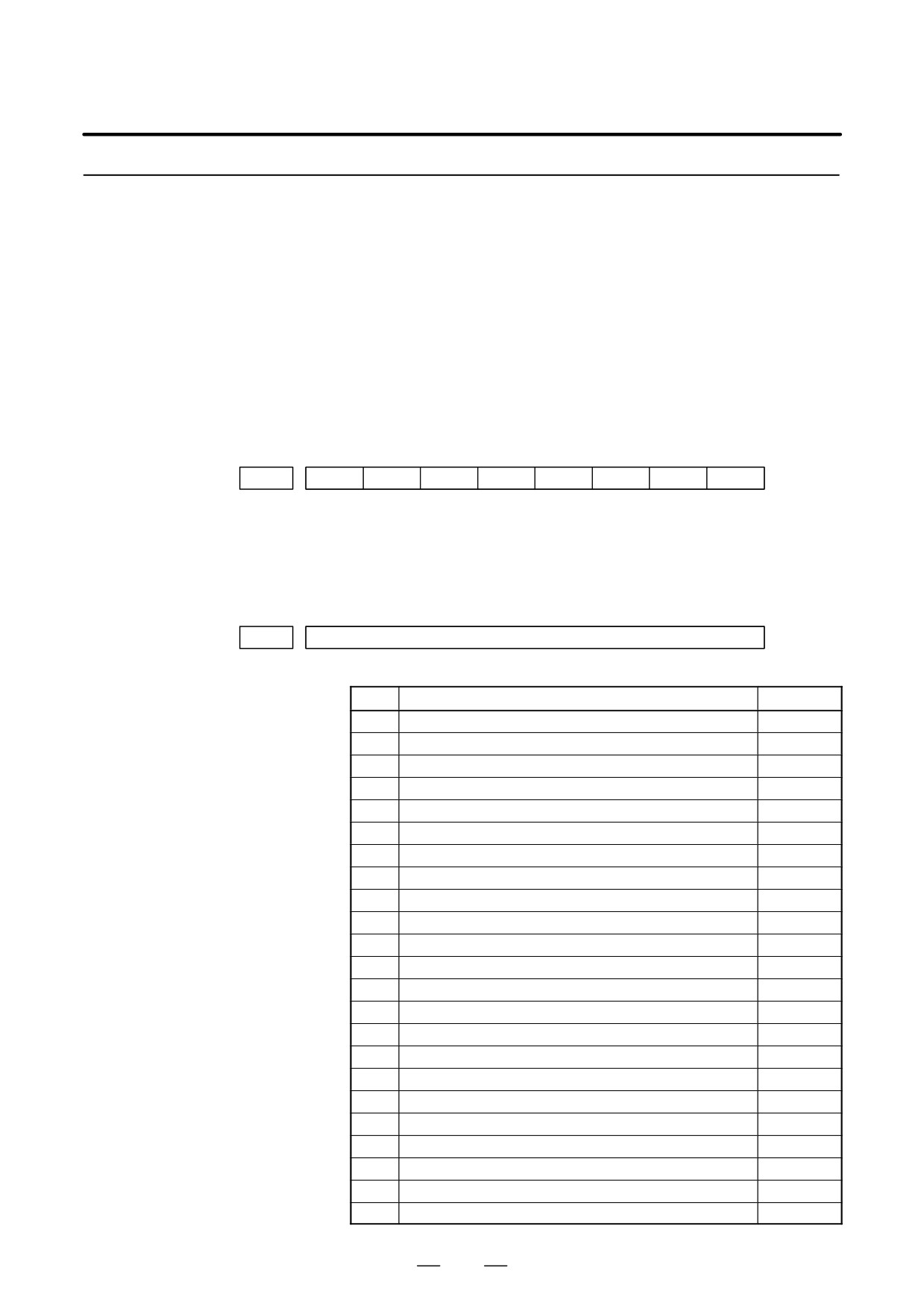
D Cs contour control mode
Numerals are parameter numbers :
S11:
S12:
S21:
S22:
1st Main
1st Sub
2nd Main
2nd Sub
Proportional gain(HIGH)
4046
4046
Proportional gain (LOW)
4047
4047
Integral gain(HIGH)
4054
4054
Integral gain(LOW)
4055
4055
Position loop gain(HIGH)
4069
4069
Position loop gain(MID,HIGH)
4070
4070
Position loop gain(MID,LOW)
4071
4071
Position loop gain(LOW)
4072
4072
Motor voltage
4086
4086
ZRN gain %
4092
4092
Reference position shift
4135
4135
D Spindle positioning
control mode
S11:
S12:
S21:
S22:
1st Main
1st Sub
2nd Main
2nd Sub
Proportionalgain(HIGH)
4044
4210
4044
4210
Proportional gain (LOW)
4045
4211
4045
4211
Integral gain(HIGH)
4052
4052
4214
4214
Integral gain(LOW)
4053
4053
Position loop gain(HIGH)
4065
4065
4221
4221
Position loop gain(MID,HIGH)
4066
4066
Position loop gain(MID,LOW)
4067
4067
4222
4222
Position loop gain(LOW)
4068
4068
Motor voltage
4085
4238
4085
4238
ZRN gain %
4091
4239
4091
4239
Reference position shift
4073
4223
4073
4223
437
7. AC SPINDLE (SERIAL INTERFACE)
B-64115EN/02
7.1.3
The standard parameters related to each motor model can be set
automatically.
Automatic Setting of
D The specifications for controlling a motor depend on the specifications
Standard Parameters
defined by the machine tool builder. The parameters defined by the
machine tool builder are set as the standard values (initial values) by
this automatic setting function.
Therefore, when performing automatic operation, always set
parameters properly according to the parameter list (parameters
4000 and later).
1. Turn on the power in the emergency stop state.
2. Set bit 7 of parameter 4019 to 1.
#7
#6
#5
#4
#3
#2
#1
#0
4019
LDSP
Bit 7 (LDSP) The parameters for the serial interface spindle are:
0 : Not set automatically.
l
1 : Set automatically.
3. Set a motor model code.
4133
Motor model code
(Reference: Example of motor model code of αi spindle motor)
Code
Motor model
Amplifier
301
αiI0.5/10000(3000/10000min-1)
αiSP2.2
302
αiI1/10000(3000/10000min-1)
αiSP2.2
304
αiI1.5/10000(1500/10000min-1)
αiSP5.5
305
αiI1.5/15000(3000/15000min-1)
αiSP15
306
αiI2/10000(1500/10000min-1)
αiSP5.5
307
αiI2/15000(3000/15000min-1)
αiSP22
308
αiI3/10000(1500/10000min-1)
αiSP5.5
309
αiI3/12000(1500/12000min-1)
αiSP11
310
αiI6/10000(1500/10000min-1)
αiSP11
311
αiI0.5/10000HV(3000/10000min-1)
αiSP5.5HV
312
αiI8/8000(1500/8000min-1)
αiSP11
313
αiI1/10000HV(3000/10000min-1)
αiSP5.5HV
314
αiI12/7000(1500/7000min-1)
αiSP15
315
αiI1.5/10000HV(1500/10000min-1)
αiSP5.5HV
316
αiI15/7000(1500/7000min-1)
αiSP22
317
αiI2/10000HV(1500/10000min-1)
αiSP5.5HV
318
αiI18/7000(1500/7000min-1)
αiSP22
319
αiI3/10000HV(1500/10000min-1)
αiSP5.5HV
320
αiI22/7000(1500/7000min-1)
αiSP26
321
αiI6/10000HV(1500/10000min-1)
αiSP11HV
322
αiI30/6000 (1150/6000min-1)
αiSP45
323
αiI40/6000(1500/6000min-1)
αiSP45
324
αiI50/4500 (1150/4500min-1)
αiSP55
438
7. AC SPINDLE (SERIAL INTERFACE)
B-64115EN/02
Code
Motor model
Amplifier
325
αiI8/8000HV (1500/8000min-1)
αiSP11HV
326
αiI12/7000HV(1500/7000min-1)
αiSP15HV
327
αiI15/7000HV(1500/7000min-1)
αiSP30HV
328
αiI22/7000HV(1500/7000min-1)
αiSP30HV
329
αiI30/6000HV (1150/6000min-1)
αiSP45HV
401
αiI6/12000(1500/12000,4000/12000min-1)
αiSP11
402
αiI8/10000(1500/10000,4000/10000min-1)
αiSP11
403
αiI12/10000(1500/10000,4000/10000min-1)
αiSP15
404
αiI15/10000(1500/10000,4000/10000min-1)
αiSP22
405
αiI18/10000(1500/10000,4000/10000min-1)
αiSP22
406
αiI22/10000(1500/10000,4000/10000min-1)
αiSP26
407
αiIP12/6000 (500/1500, 750/6000min-1)
αiSP11
408
αiIP15/6000 (500/1500, 750/6000min-1)
αiSP15
409
αiIP18/6000 (500/1500, 750/6000min-1)
αiSP15
410
αiIP22/6000 (500/1500, 750/6000min-1)
αiSP22
411
αiIP30/6000 (400/1500, 575/6000min-1)
αiSP22
412
αiIP40/6000 (400/1500, 575/6000min-1)
αiSP26
413
αiIP50/6000(575/1500, 1200/6000min-1)
αiSP26
414
αiIP60/4500 (400/1500, 750/4500min-1)
αiSP30
415
αiI100/4000HV(1000/3000,2000/4000min-1)
αiSP75HV
418
αiIP40/6000HV(400/1500, 575/6000min-1)
αiSP30HV
(Reference: Example of motor model code of βi spindle motor)
Code
Motor model
Amplifier
332
βiI3/10000(2000/10000min-1)
βiSVSP-5.5
333
βiI6/10000(2000/10000min-1)
βiSVSP-11
334
βiI8/8000(2000/8000min-1)
βiSVSP-11
335
βiI12/7000(2000/7000min-1)
βiSVSP-15
For motor model codes other than the above, refer to the parameter
manual for spindles.
The α Series cannot be used with the 0i Mate.
4. Turn off the power then back on. Then, the parameters are read.
439
7. AC SPINDLE (SERIAL INTERFACE)
B-64115EN/02
7.1.4
Warning Interface for
the αi Spindle
Overview
For the αi spindle, the warning state can be reported before an alarm is
issued. When the warning state is entered, a report to the PMC is sent.
For example, this signal can be used for retracting tools or reducing
cutting load from the time a warning occurs by the time an overheat alarm
occurs. In addition, diagnostic information also contains warning
numbers.
Signal
Spindle warning detailed
signals
SPWRN1 to 9
<F264#0 to #7, F265#0>
[Classification]
Output
[Function]
Reports the warning number corresponding to the state of the αi spindle
amplifier.
[Output condition]
When the αi spindle is in the warning state, a warning number consisting
of SPWRN1 to SPWRN9 is output as nine-bit binary data.
If warnings occurred on multiple αi spindle amplifiers, the warning
number of the αi spindle having the smallest axis number is output.
However, when there is no αi spindle or the system configuration of the
spindle includes an additional spindle that is older than the αi spindle, this
function is invalid for all spindles.
The warning numbers and their descriptions are shown below.
Warning
Contents
Details
number
56
Internal fan
If the internal fan stops, the warning signal is output.
stopped
Since the spindle continues to operate at this time,
use the PMC to perform processing as needed.
About one minute after the warning signal is output,
an alarm occurs.
88
Radiator cooling
If the radiator cooling fan stops, the warning signal is
fan stopped
output. Since the spindle continues to operate at this
time, use the PMC to perform processing as needed.
If the main circuit overheats, an alarm occurs.
04
Open-phase de-
If an open-phase is detected in the main power sup-
tected in the con-
ply, the warning signal is output. Since the spindle
verter main pow-
continues to operate at this time, use the PMC to per-
er supply
form processing as needed.
About one minute (for the PSM) or about five se-
conds (for the PSMR) after the warning signal is out-
put, an alarm occurs.
440
7. AC SPINDLE (SERIAL INTERFACE)
B-64115EN/02
Warning
Contents
Details
number
58
Converter main
If the main circuit of the PSM is overloaded, the warn-
circuit overloaded
ing signal is output. Since the spindle continues to
operate at this time, use the PMC to perform proces-
sing as needed.
About one minute after the warning signal is output,
an alarm occurs.
59
Converter cooling
If the PSM cooling fan stops, the warning signal is
fan stopped
output. Since the spindle continues to operate at this
time, use the PMC to perform processing as needed.
About one minute after the warning signal is output,
an alarm occurs.
113
Converter radia-
If the PSM radiator cooling fan stops, the warning
tor cooling fan
signal is output. Since the spindle continues to oper-
stopped
ate at this time, use the PMC to perform processing
as needed.
If the PSM main circuit overheats, an alarm occurs.
Signal address
#7
#6
#5
#4
#3
#2
#1
#0
F264
SPWRN8
SPWRN7
SPWRN6
SPWRN5
SPWRN4
SPWRN3
SPWRN2
SPWRN1
F265
SPWRN9
Diagnosis screen
The status of a warning is displayed on the following diagnostic screen.
712
Warning status of first spindle
713
Warning status of second spindle
732
Warning status of third spindle
733
Warning status of fourth spindle
The number of a warning caused on each spindle is indicated.
If there is no warning, 0 is indicated.
NOTE
NOTE
1
For spindles that are older than the αi spindle, this function
is invalid.
2
When the system configuration of the spindle (even another
spindle) includes an additional spindle that is older than the
αi spindle, this function is invalid.
441
7. AC SPINDLE (SERIAL INTERFACE)
B-64115EN/02
7.1.5
αi Spindle Error State
Messages
General
If an error occurs (a yellow LED lights and an error number is displayed)
on the αi spindle amplifier, the error state is displayed on the diagnosis
screen.
Diagnosis screen
710
First-spindle error state
711
Second-spindle error state
730
Third-spindle error state
731
Fourth-spindle error state
The error number for an error on an individual spindle amplifier is
indicated.
If no error occurs, “0” is indicated.
NOTE
- If the system contains an old-type spindle amplifier (such
as one for an α spindle), no spindle amplifier error is
indicated.
- Refer to the αi Servo Motor Maintenance Manual and the
like for details of the spindle amplifier errors.
442
7. AC SPINDLE (SERIAL INTERFACE)
B-64115EN/02
7.1.6
αi Spindle Information
Screen
General
In the αi spindle system, ID information output from each of the
connected units is obtained and output to the CNC screen.
The units that have ID information are shown below.
(Remark: Some instances of these units do not have ID information.)
S Spindle motor
S Spindle amplifier
S Power supply module
ID information is automatically read from each of the connected units
during first startup of the CNC and then recorded. During second or later
startup, the ID information recorded during first startup can be compared
with the ID information read this time on the screen to check whether the
configuration of the connected units is changed. (If there is a difference
between them, the alarm mark (*) appears.)
The recorded ID information can be edited. Therefore, the ID information
of an unit that does not have ID information can be displayed. (However,
the alarm mark (*) indicating a difference between these IDs appears.)
Parameter
#7
#6
#5
#4
#3
#2
#1
#0
13112
SPI
IDW
[Data type] Bit
IDW The edit of the servo information screen or the spindle information screen
is:
0 : Prohibited
1 : Allowed
SPI The spindle information screen is:
0 : Displayed
1 : Not displayed
443
7. AC SPINDLE (SERIAL INTERFACE)
B-64115EN/02
Displaying the spindle information screen
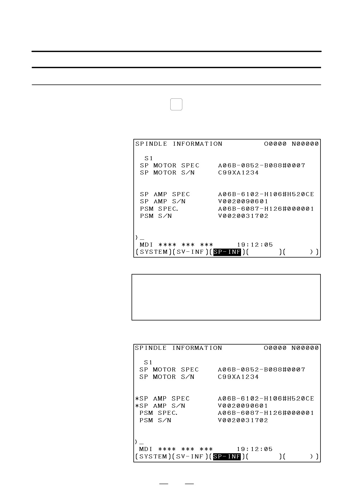
SYSTEM
1
Press the
function key, then press the [SYSTEM] soft key.
2
Press the [SP-INF] soft key to display the screen as shown below.
NOTE
Spindle information is stored in flash ROM. If there is a
difference between the spindle information in flash ROM
and the actual spindle information, the corresponding items
are preceded by *, as shown below.
444
7. AC SPINDLE (SERIAL INTERFACE)
B-64115EN/02
Additional Information
Even if replacement is performed reasonably such as for
repairing, this function incorrectly indicates the * mark when
it detects the replacement.
To clear the * mark, follow the steps below to update the
registered data, as described in the editing section later.
(1)Make the registered data editable. (Parameter IDW (No.
13112#0) = 1)
(2)On the edit screen, place the cursor on the item from
which you want to delete the * mark.
(3)Operate the soft keys [CHANGE], [INPUT], and [SAVE]
in that order.
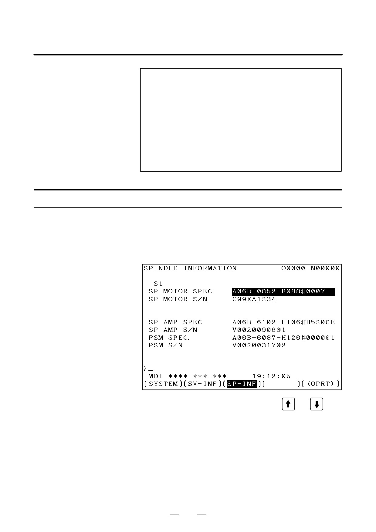
Editing the spindle information screen
1
Assume that parameter No.13112#0(IDW) = 1.
2
Press the MDI switch on the machine operator’s panel.
3
Follow the steps shown in ”Displaying the spindle ID screen” to
display the screen as shown below.
4
To move key-in buffer on the screen, use the
and
keys.
445
7. AC SPINDLE (SERIAL INTERFACE)
B-64115EN/02
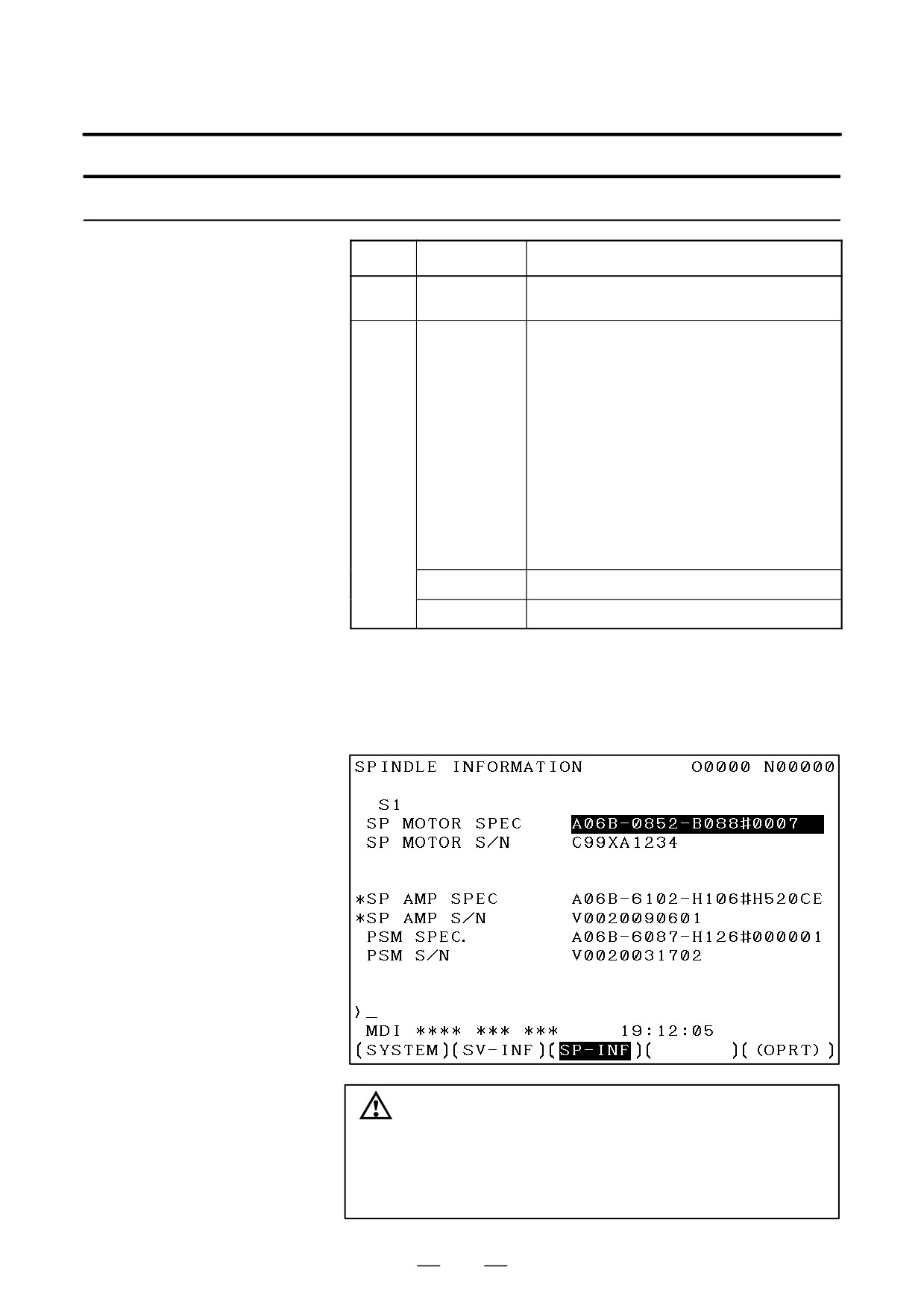
Screen operation on the editing screen
Mode
Key operation
Use
Viewing
Page key
Scrolls up or down on a screen-by-screen basis.
(*1)
Editing
Soft key
(*2)
[INPUT]
Replace the selected ID information at the cursor posi-
tion with the character string in key-in buffer.
[CANCEL]
Deletes the character string in key-in buffer.
[CHANGE]
Transfers the selected ID information at the cursor posi-
tion that was sent by the servo, to key-in buffer. Only
the items preceded by * (*3) are valid.
[SAVE]
Saves the ID information that has been changed on the
spindle information screen in flash ROM.
[RELOAD]
Cancels the ID information that has been changed on
the spindle information screen and loads ID information
from flash ROM.
Page key
Scrolls up or down on a screen-by-screen basis.
Cursor key
Scrolls up or down the selection of ID information.
*1 Viewing mode: when parameter No.13112#0 = 0
*2 Editing mode: when parameter No.13112#0 = 1
*3 Spindle information is stored in flash ROM. If there is a difference
between the spindle information in flash ROM and the actual spindle
information, the corresponding items are preceded by *.
CAUTION
For mixed connection of an αi spindle and a spindle that
does not belong to the αi spindle system, ID information of
connected units for serial spindle including ai spindles
cannot be obtained.
446

7. AC SPINDLE (SERIAL INTERFACE)
B-64115EN/02
7.2
AC SPINDLE
(ANALOG
INTERFACE)
7.2.1
Outline of Spindle
Control
447
7. AC SPINDLE (SERIAL INTERFACE)
B-64115EN/02
7.2.1.1
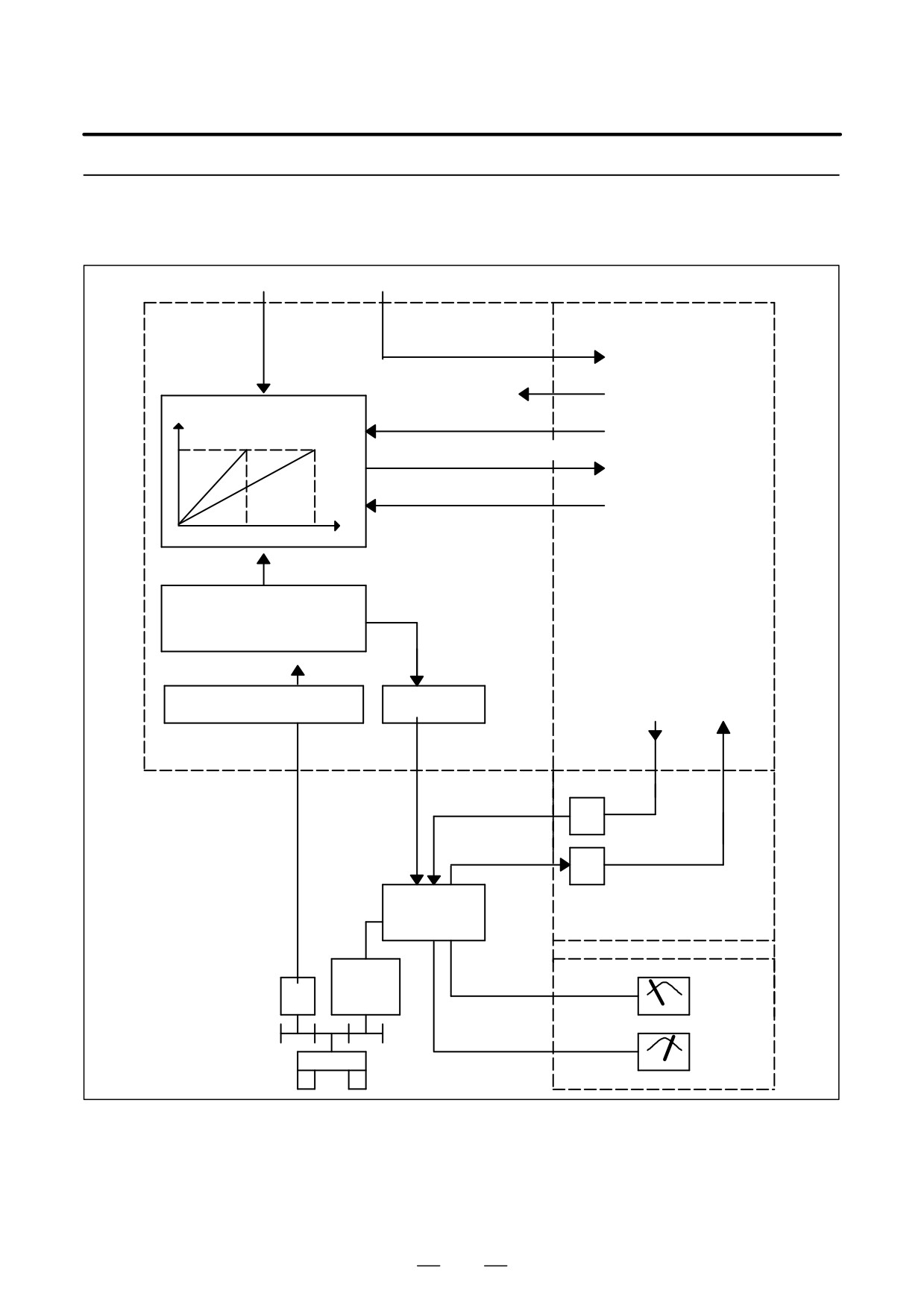
Block diagram
S command
M command
PMC
NC
M03 to M05, M06, M19
CW/CCW command,
Spindle speed
orientation, etc.
conversion
FIN
Miscellaneous function end
Motor speed
*SSTP
Spindle stop
Gear 1
Gear 2
GR1O, GR2O, GR3O
Gear selection (16M/18M)
GR1, GR2
Gear information (16T/18T)
S
Maximum spindle speed and other
parameters
PRM 3714 to 3743, 3735, 3736,
3751 and 3752 (M series)
PRM 3741 to 3744 (T series)
*ESP, MRDY SAR, LDT
SFR, SRV
SST, ORAR
ORCM, TLM
SDT, ALM
Position coder interface
D/A converter
PRM 3730 (gain)
PRM 3731 (offset)
DV
SVC
RV
I/O card or I/O unit
Spindle amplifier
Operator’s panel
Spindle
PC
motor
Load meter
LM
Speedometer
Spindle
SM
448
7. AC SPINDLE (SERIAL INTERFACE)
B-64115EN/02
7.2.1.2
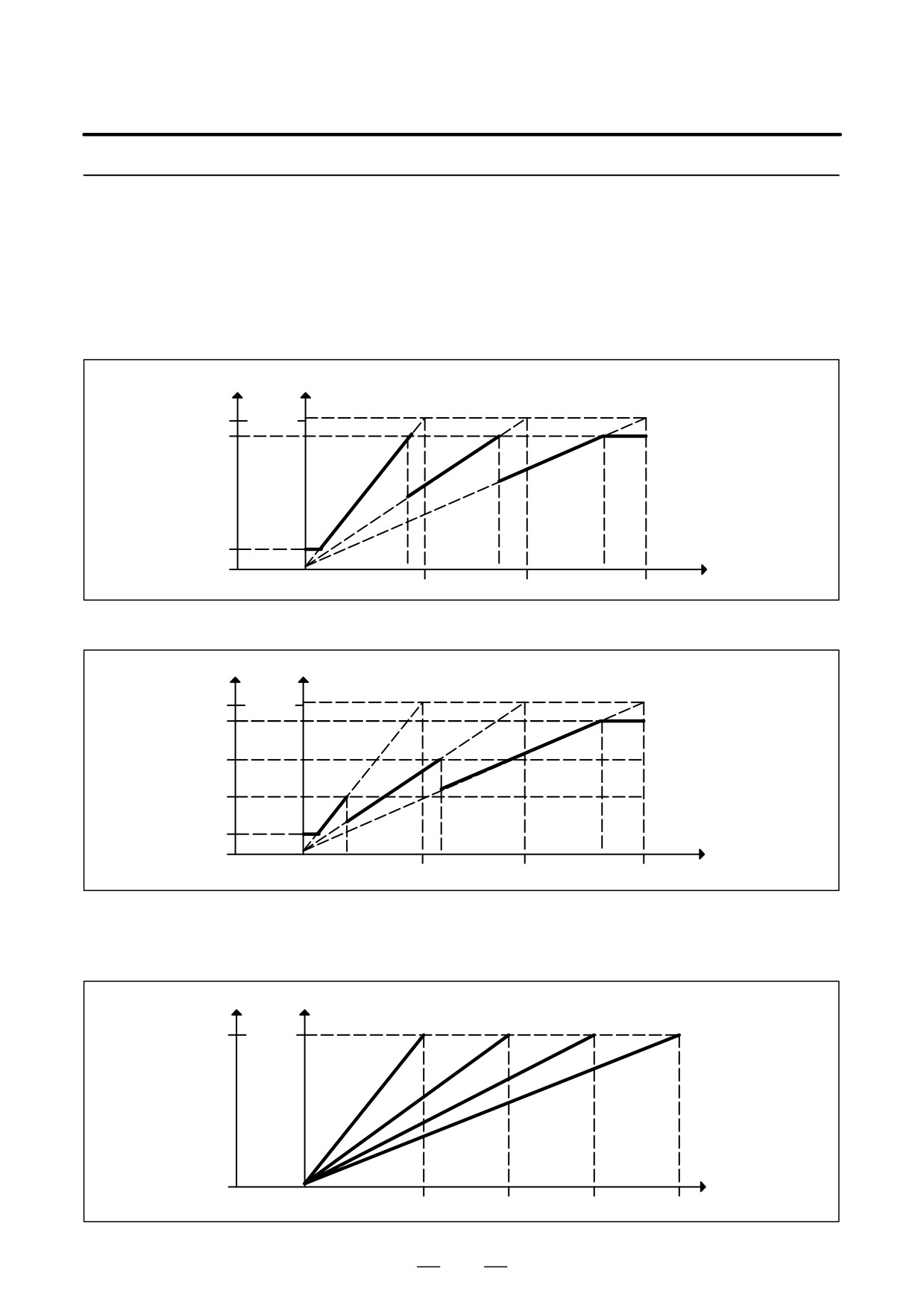
Calculation of S analog
voltage and related
parameters
[M series]
1
Gear change method A (bit 2 of parameter 3705 = 0)
SVC
Motor speed
Gear 1
Gear 2
Gear 3
(4095) 10V
Max
PRM 3736
PRM 3735
0V
S code
0
PRM 3741
PRM 3742
PRM 3743
(min-1)
2
Gear change method B (bit 2 of parameter 3705 = 1)
SVC
Motor speed
Gear 1
Gear 2
Gear 3
Max
(4095) 10V
PRM 3736
PRM 3752
PRM 3751
PRM 3735
0V
S code
0
PRM 3741
PRM 3742
PRM 3743
(min-1)
[T series]
Constant surface speed control
SVC Motor speed
Gear 1
Gear 2
Gear 3
Gear 4
(4095) 10V
Max
0V
S code
0
PRM 3741
PRM 3742
PRM 3743
PRM 3744
(min-1)
449
7. AC SPINDLE (SERIAL INTERFACE)
B-64115EN/02
#7
#6
#5
#4
#3
#2
#1
#0
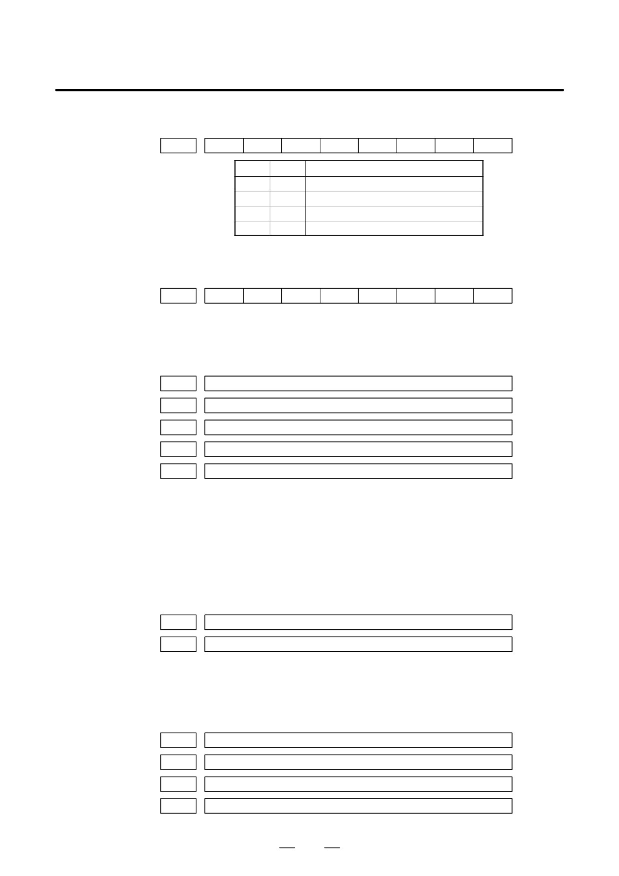
3706
TCW
CWM
TCW
CWM
Sign of output voltage
0
0
Analog voltage (+) with both M03 and M04
0
1
Analog voltage (-) with both M03 and M04
1
0
(+) with M03, (-) with M04
1
1
(-) with M03, (+) with M04
[M series]
#7
#6
#5
#4
#3
#2
#1
#0
3705
SGB
SGB
Spindle speed set when gear change is performed is:
0 : Maximum speed for each gear.
1 : Set by respective parameters. (Parameters 3751, 3752)
3741
Max. spindle speed of gear 1 (1 to 9999) [min-1]
3742
Max. spindle speed of gear 2 (1 to 9999) [min-1]
3743
Max. spindle speed of gear 3 (1 to 9999) [min-1]
3751
Spindle motor speed at the switch point between gear 1 and gear 2
3752
Spindle motor speed at the switch point between gear 2 and gear 3
[Data type]
Word
[Valid data range]
0 to 4095
Set a spindle motor speed at each gear switch point when gear switch
method B is used (when bit 2 (SGB) of parameter No. 3705 is set to 1).
Setting +Spindlemotorspeedatgearswitchpoint
4095
Maximum spindle motor speed
3736
Upper limit of the output to the spindle motor
3735
Lower limit of the output to the spindle motor
Setting +Spindlespeed(upperlimitńlowerlimit)
4095
Max. spindle speed
[T series]
3741
Max. spindle speed of gear 1 (1 to 9999) [min-1]
3742
Max. spindle speed of gear 2 (1 to 9999) [min-1]
3743
Max. spindle speed of gear 3 (1 to 9999) [min-1]
3744
Max. spindle speed of gear 4 (1 to 9999) [min-1]
450
7. AC SPINDLE (SERIAL INTERFACE)
B-64115EN/02
7.2.1.3
Tuning S analog voltage
(D/A converter)
(1) For M series, change the upper and lower limits as follows:
⋅ When gear change method A is used: Parameter 3736 = 4095,
parameter 3735 = 0
⋅ When gear change method B is used: Parameter 3751 = 4095,
parameter 3735 = 0
. For T series, these changes are not required.
(2) Tuning the D/A converter offset
Specify zero as the spindle speed. Then, by using a digital multimeter,
adjust the following parameter so that the voltage at the test pin DA2
on the spindle amplifier printed circuit board is 0 mV.
1
For M series
S0; (Specify the command by MDI operation, then press the cycle start button.)
2
For T series (in case of G-code system A)
G97 S0;
(Specify the command by MDI in the same manner as for M series.)
3731
Spindle speed (D/A converter) offset compensation value
(3) Tuning the D/A converter gain
Specify the maximum spindle speed of gear 1. Then, by using a digital
multimeter, adjust the following parameter so that the voltage at the
test pin DA2 on the spindle amplifier printed circuit board is 10.0 V.
1
For M series
Sxxxx ;
(xxxx is the value set in parameter 3741.)
(Specify the command by MDI operation, then press the cycle start button.)
3741
Max. spindle speed of gear 1 (1 to 9999) [min-1]
2
For T series (in case of G-code system A)
G97 Sxxxx ;
(xxxx is the value set in parameter 3741.)
(Specify the command by MDI operation, then press the cycle start button.)
3741
Max. spindle speed of gear 1 (1 to 9999) [min-1]
. Usually a voltage is output from the D/A converter by only
executing an S command. However, the clockwise rotation
command (M03) may be required on some machines.
451

7. AC SPINDLE (SERIAL INTERFACE)
B-64115EN/02
(4) If the output voltage is not correct, perform the following calculation,
and change the value of parameter 3730 to adjust the gain of the D/A
converter:
10V
Setting +
(Current value of PRM 3730)
Measured voltage
(5) Execute an S command again and confirm that the output voltage is
correct.
.Restore the original parameter values.
452
B-64115EN/02
8. TROUBLESHOOTING
TROUBLESHOOTING
8
This chapter describes troubleshooting procedure.
8.1
CORRECTIVE ACTION FOR FAILURES
455
8.2
NO MANUAL OPERATION NOR AUTOMATIC
OPERATION CAN BE EXECUTED
457
8.3
JOG OPERATION CANNOT BE DONE
461
8.4
MANUAL HANDLE OPERATION
CANNOT BE DONE
465
8.5
AUTOMATIC OPERATION
CANNOT BE DONE
470
8.6
CYCLE START LED SIGNAL HAS
TURNED OFF
478
8.7
NOTHING IS DISPLAYED ON THE LCD
WHEN THE POWER IS TURNED ON
480
8.8
INPUT FROM AND OUTPUT TO I/O DEVICES
CANNOT BE PERFORMED INPUT/OUTPUT
CANNOT BE PERFORMED PROPERLY
482
8.9
IN A CONNECTOR PANEL I/O UNIT, DATA IS
INPUT TO AN UNEXPECTED ADDRESS
484
8.10
IN A CONNECTOR PANEL I/O UNIT, NO DATA IS
OUTPUT TO AN EXPANSION UNIT
485
8.11
ALARM 85 TO 87
(READER/PUNCHER INTERFACE ALARM)
486
8.12
ALARM 90 (REFERENCE POSITION
RETURN IS ABNORMAL)
490
8.13
ALARM 300 (REQUEST FOR REFERENCE
POSITION RETURN)
492
8.14
ALARM 401 (V READY OFF)
493
8.15
ALARM 404 (V READY ON)
495
8.16
ALARM 462 (SEND CNC DATA FAILED)
ALARM 463 (SEND SLAVE DATA FAILED)
496
8.17
ALARM 417
(DIGITAL SERVO SYSTEM IS ABNORMAL) . . . 497
8.18
ALARM 700 (OVERHEAT: CONTROL UNIT) . . . 498
8.19
ALARM 701 (OVERHEAT: FAN MOTOR)
499
8.20
ALARM 704 (SPINDLE SPEED
FLUCTUATION DETECTION ALARM)
500
8.21
ALARM 749 (SERIAL SPINDLE
COMMUNICATION ERROR)
501
8.22
ALARM 750
(SPINDLE SERIAL LINK STARTUP FAILURE) . .
502
453

8. TROUBLESHOOTING
B-64115EN/02
8.23
ALARM 5134 (FSSB: OPEN READY TIME OUT)
ALARM 5135 (FSSB: ERROR MODE)
ALARM 5137 (FSSB: CONFIGURATION ERROR)
ALARM 5197 (FSSB: OPEN TIME OUT)
ALARM 5198 (FSSB: ID DATA NOT READ)
504
8.24
ALARM 5136
(FSSB: NUMBER OF AMPS IS SMALL)
506
8.25
ALARM 900 (ROM PARITY)
507
8.26
ALARMS 912 TO 919 (DRAM PARITY)
508
8.27
ALARM 920 (SERVO ALARMS)
509
8.28
ALARM 926 (FSSB ALARM)
510
8.29
ALARM 930 (CPU INTERRUPT)
513
8.30
ALARM 935 (SRAM ECC ERROR)
514
8.31
ALARM 950 (PMC SYSTEM ALARM)
515
8.32
ALARM 951 (PMC WATCHDOG ALARM)
518
8.33
ALARM 972 (NMI ALARM ON AN OPTION
BOARD) (Series 0i-C ONLY)
519
8.34
ALARM 973 (NMI ALARM WITH AN
UNKNOWN CAUSE)
520
8.35
ALARM 974 (F-BUS ERROR)
521
8.36
ALARM 975 (BUS ERROR)
522
8.37
ALARM 976 (LOCAL BUS ERROR)
523
8.38
SERVO ALARMS
524
8.39
SPC ALARMS
527
8.40
SPINDLE ALARMS
528
454
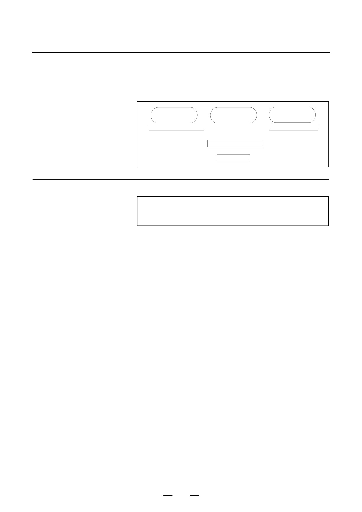
B-64115EN/02
8. TROUBLESHOOTING
When a failure occurs, it is important to correctly grasp what kind of
8.1
failure occured and take appropriate action, to promptly recover the
CORRECTIVE
machine.
ACTION FOR
Check for the failure according to the following procedure :
FAILURES
With what
When?
What failure?
operation?
Grasp the kind of failure
↓
Appropriate action
↓
Recovery
8.1.1
Investigating the
(1) When and how many times (frequency of occurrences)
Conditions Under
(2) With what operation
(3) What failure occurred
which Failure Occurred
1
When did the failure occur?
⋅
Date and time?
⋅
Occurred during operation? (how long was the operation?)
⋅
Occurred when the power was turned on?
⋅
Was there any lightening surge, power failure, or other disturbances
to the power supply?
How many times has it occurred
⋅
Only once?
⋅
Occurred many times ? (How many times per hour, per day, or per
month?)
2
With what operation did it occur ?
⋅
What was the NC mode when the failure occurred?
Jog mode/memory operation mode /MDI mode /reference position
return mode
⋅
If during program operation,
1) Where in the program ?
2) Which program No. and sequence No. ?
3) What program ?
4) Occurred during axial movement ?
5) Occurred during the execution of an M/S/T code ?
6) Failure specific to the program ?
⋅
Does the same operation cause the same failure ?
(Check the repeatability of the failure.)
⋅
Occurred during data input/output ?
<Feed axes and spindles>
⋅
For a failure related to feed axis servo
1) Occurred at both low feedrate and high feedrate ?
2) Ocurred only for a certain axis ?
455

8. TROUBLESHOOTING
B-64115EN/02
⋅
For a failure related to spindles
When did the failure occur ? (during power-on, acceleration,
deceleration, or constant rotation)
3
What failure occurred ?
⋅
Which alarm was displayed on the alarm display screen?
(Check the axis along which an alarm has occurred for alarms 300
to 599.)
⋅
Is the screen correct ?
⋅
If machining dimensions are incorrect
1) How large is the error ?
2) Is the position display on the CRT correct ?
3) Are the offsets correct ?
4
Other information
⋅
Is there noise origin around machine?
If the failure has not occurred frequently, the cause may be external
noise to the power supply or inductive noise on machinery cables.
Operate other machines connected to the same power line and see
if noise come from the relays or compressors.
⋅
Is it taken any countermeasure for noise in machine side?
⋅
Check the following for the input power supply voltage :
1) Is there variation in the voltage ?
2) Are the voltages different depending on the phase ?
3) Is the standard voltage supplied ?
⋅
How high is the ambient temperature of the control unit?
Refer to manual about noise.
⋅
Has excessive vibration been applied to the control unit?
5
When you contact our service center, specify the following items :
1) Name of the NC unit
2) Name of the machine tool builder and type of machine
3) Software series/version of the NC
4) Specifications of the servo amplifier and motor
(for a failure related to the servo)
5) Specifications of the spindle amplifier and spindle motor
(for a failure related to a spindle)
⋅
See the drawing issued by the machine tool builder for the locations
of the NC unit and servo/spindle amplifiers.
⋅
We use the following specification codes :
Servo /spindle amplifier : A06B-VVVV-HVVV
Servo/spindle amplifier
: A06B-VVVV-BVVV
NOTE
The mark ‘V’ represents a number.
456
B-64115EN/02
8. TROUBLESHOOTING
8.2
NO MANUAL OPERA-
TION NOR AUTOMAT-
IC OPERATION CAN
BE EXECUTED
Points
(1) Execute the following procedure when no manual nor automatic
operation is done
(2) Check whether position display shows correct position
(3) Check CNC status display
(4) Check CNC internal status using diagnostic function
Causes and
Countermeasures
1. Position display
(1) Check CNC status display (Refer to Section 1.9 CNC STATUS
(relative, absolute,
DISPLAY for detail.)
machine coordinate)
(a) Emergency stop status (Emergency stop signal is turned on)
does not change
If status display shows
EMG
the emergency stop signal is input.
Check the following signal using the PMC’s diagnostic function
(PMCDGN).
#7
#6
#5
#4
#3
#2
#1
#0
X1008
*ESP
G0008
*ESP
ESP=0 indicates that emergency stop signal is input.
(b) It is a reset status
When RESET is displayed, any of a reset is functioned. Check the
following signal using the PMC’s diagnostic funciton
(PMCDGN).
1) An input signal from the PMC functions
#7
#6
#5
#4
#3
#2
#1
#0
G0008
ERS
RRW
When ERS is 1, external reset signal is input.
When RRW is 1, reset & rewing signal is input.
2) RESET key on the MDI keyboard functions
When the signals in 1) are 0,
RESET
key may be functioning.
Check the contact of
RESET
key using a tester.
When it is abnormal, change the keyboard.
457
8. TROUBLESHOOTING
B-64115EN/02
(c) Confirm the status of modes
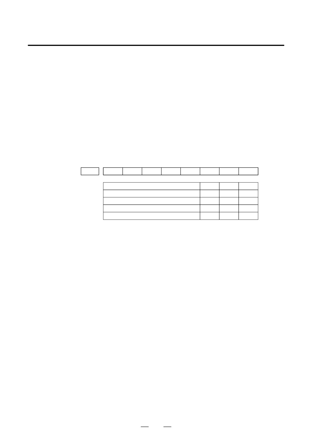
Operation mode status is displayed on the lower part of CRT as
follows :
If nothing is displayed, mode select signal is not input. Check mode
select signal using PMC’s diagnostic function (PMCDGN).
For details, refer to section 1.9 CNC STATUS DISPLAY.
(Example of display)
JOG : Manual operation (JOG) mode
HND : Manual handle (MPG) mode
MDI : Manual data input (MDI) mode
MEM : Automatic operation (Memory) mode
EDIT: EDIT (Memory edit) mode
<Mode select signal>
#7
#6
#5
#4
#3
#2
#1
#0
G0043
MD4
MD2
MD1
↓
↓
↓
Manual operation (JOG) mode
1
0
1
Manual handle (MPG) mode
1
0
0
Manual data input (MDI) mode
0
0
0
Automatic operation (Memory) mode
0
0
1
EDIT (Memory edit) mode
0
1
1
(2) Check diagnostic data 000 to 025 of the CNC Check an item for which
1 is displayed
No. Message
Display
000
WAITING FOR FIN SIGNAL
: 0
001
MOTION
: 0
002
DWELL
: 0
a.003
IN-POSITION CHECK
: 0
004
FEEDRATE OVERRIDE 0%
: 0
b.005
INTERLOCK / START LOCK
: 1 (Example)
006
SPINDLE SPEED ARRIVAL CHECK
: 0
010
PUNCHING
: 0
011
READING
: 0
012
WAITING FOR (UN) CLAMP
: 0
c.013
JOG FEEDRATE OVERRIDE 0%
: 0
d.014
WAITING FOR RESET, ESP, RRW OFF
: 0
015
EXTERNAL PROGRAM NUMBER SEARCH : 0
Items with a to d relate with manual and automatic operation and its
detail is shown below.
458
B-64115EN/02
8. TROUBLESHOOTING
a. In-position check is
It shows that positioning is not yet completed. Check the contents of the
being done
following diagnostic number. (It is 1 in the following condition)
DGN 0300
Position Error
>PARAM 1826
In-position width
1) Check the parameters according to the parameter list.
1825
Servo loop gain per axis
(Normal : 3000)
2) Servo system may be abnormal. Refer to servo alarm 400, 410, and
411.
b. Interlock or start lock
There are a plural interlock signals. Check at first which interlock signal
signal is input
is used by the machine tool builder at the parameters shown below.
#7
#6
#5
#4
#3
#2
#1
#0
3003
DAU
DIT
ITX
ITL
#0 ITL=0 shows interlock signal *IT is effective. Go to 1).
#2 ITX=0 shows interlock signal *ITn is effective. Go to 2).
#3 DIT=0 shows interlock signal "MITn is effective. Go to 3).
#4 DAU=When it is “1,” the interlock signal ("MITn) is effective
even in automatic operation.
Go to 3).
Check state of effective interlock signals using the diagnostic function
(PMCDGN) of the PMC.
1)
Interlock signal (*IT) is input.
#7
#6
#5
#4
#3
#2
#1
#0
G0008
*IT
*IT=0 shows that interlock signal is input.
2)
Axis interlock signal (*ITn) is input.
#7
#6
#5
#4
#3
#2
#1
#0
G0130
*IT4
*IT3
*IT2
+IT1
*ITn=0 shows interlock signal is input.
3)
Interlock signal per axis and direction ("MITn) is input.
D M series
#7
#6
#5
#4
#3
#2
#1
#0
G0132
+MIT4
+MIT3
+MIT2
+MIT1
G0134
-MIT4
-MIT3
-MIT2
-MIT1
D T series
#7
#6
#5
#4
#3
#2
#1
#0
X0004
-MIT2
+MIT2
-MIT1
+MIT1
"MITn=1 shows interlock signal per axis and direction is input.
* In T series, "MITn is effective only when the manual operation is
used.
459